JP2004016660A - Demonstration tool for game machine - Google Patents
Demonstration tool for game machine Download PDFInfo
- Publication number
- JP2004016660A JP2004016660A JP2002178959A JP2002178959A JP2004016660A JP 2004016660 A JP2004016660 A JP 2004016660A JP 2002178959 A JP2002178959 A JP 2002178959A JP 2002178959 A JP2002178959 A JP 2002178959A JP 2004016660 A JP2004016660 A JP 2004016660A
- Authority
- JP
- Japan
- Prior art keywords
- symbol display
- control board
- display
- demonstration
- demonstration tool
- Prior art date
- Legal status (The legal status is an assumption and is not a legal conclusion. Google has not performed a legal analysis and makes no representation as to the accuracy of the status listed.)
- Withdrawn
Links
Images


Landscapes
- Pinball Game Machines (AREA)
- Display Devices Of Pinball Game Machines (AREA)
Abstract
Description
【0001】
【発明の属する技術分野】本発明は、複数の図柄表示演出の1つをランダムに選択して実行する遊技機に関し、詳しくは、この遊技機で行われる図柄表示演出のデモンストレーションを効率的に行うための技術に関する。
【0002】
【従来の技術】例えば、遊技機の一種であるパチンコ機では、遊技機本体に組み付けられた図柄表示装置で種々の図柄表示演出が行われる。近年、図柄表示装置で行われる図柄表示演出が遊技者の遊技的興味の大部分を占め、図柄表示演出が面白いか否かが遊技機の面白さを決定するようになっている。したがって、遊技機の販売促進等のためには、図柄表示装置で行われる図柄表示演出を実際に表示して見せること(デモンストレーション)が有効な手段となっている。
【0003】
【発明が解決しようとする課題】しかしながら、実際の遊技機では、遊技者の飽きを防止するため予め複数の図柄表示演出を用意しておき、乱数抽選によって複数の図柄表示演出の中から1つをランダムに選択して実行されるようになっている。このため、実機を用いて図柄表示演出のデモンストレーションを行おうとすると、所望の図柄表示演出を表示するまでに非常に多くの図柄表示演出を実行させる必要が生じることとなる。したがって、デモンストレーションのための限られた時間内では、希望する図柄表示演出が表示されない場合があった。
【0004】
本発明は上述した点に鑑みなされたものであり、その目的は、効率的にデモンストレーションを行うことができる遊技機用のデモンストレーションツールを提供する。
【0005】
【課題を解決するための手段、作用及び効果】上記課題を解決するため請求項1に記載の装置は、複数の図柄表示演出の1つをランダムに選択して実行する遊技機用のデモンストレーションツールであって、複数の図柄表示演出を実行可能な図柄表示装置と、複数の図柄表示演出の中から1の図柄表示演出を選択するため操作者によって操作される選択装置と、その選択装置で選択された図柄表示演出を図柄表示装置に実行させる制御装置とを有する。そして、図柄表示装置が制御装置に対し着脱可能に接続されている。
上記遊技機用デモンストレーションツールでは、選択装置により1の図柄表示演出を選択すると、その選択された図柄表示演出が図柄表示装置で実行される。したがって、図柄表示装置で実行される図柄表示演出を直接選択することができるため、効率的にデモンストレーションを行うことができる。また、図柄表示装置が制御装置に対し着脱可能となっているため、必要に応じて両者を着脱することができる。したがって、デモンストレーション会場への運搬の際等の取り扱いが向上する。
【0006】
また、遊技機の中には、遊技盤に設けられた表示領域に図柄表示演出が表示されるものがある。このような遊技機では、遊技者は図柄表示演出と遊技盤の表面に描かれた表示(例えば、絵)を同時に視認することとなる。したがって、図柄表示演出に関連付けて遊技盤の表示をデザインする場合も多い。かかる場合には、請求項2に記載の装置によって効率的にデモンストレーションを行うことができる。
すなわち、請求項2に記載の装置は、遊技盤に設けられた表示領域に図柄表示演出が表示される遊技機用の請求項1記載のデモンストレーションツールであって、前記図柄表示装置が取付けられる取付部が、前記遊技盤の少なくとも一部で形成される。
このような構成によると、遊技盤の少なくとも一部で形成された取付部と図柄表示装置で表示される図柄表示演出とを同時に見せることができる。このため、より効果的にデモンストレーションを行うことができる。
なお、ここでいう「遊技盤」とは、遊技機に装備される部材であって、図柄表示演出が表示される表示領域が設けられたものを意味する。例えば、パチンコ機においては、図柄表示演出を表示する表示器が取り付けられた遊技盤が相当し、スロットマシンにおいては、ドラム装置に描かれた図柄列の一部を表示するための表示窓を備えた前面パネルが相当する。
【0007】
なお、選択装置としては、操作者が簡単な操作によって所望の図柄表示演出を選択できることが好ましい。このため、選択装置は複数の図柄表示演出のそれぞれに対応付けられたコードを入力するコード入力手段を有し、制御装置はコード入力手段から入力されたコードに対応する図柄表示演出を前記図柄表示装置に実行させることが好ましい。このような構成によると、操作者はコードを入力するだけでよいので、簡易な操作によって所望の図柄表示演出を選択することができる。
この場合は、前記コード入力手段で入力されるコード毎に、そのコードに対応する図柄表示演出を示す「コード−図柄表示演出」の一覧を表示する表示部がさらに設けられていることが好ましい。
このような構成によると、操作者は表示部に表示されている「コード−図柄表示演出」の一覧を見ながらコードを入力することができるので、所望の図柄表示演出を誤り無く選択することができる。
ここでいう「表示部」には、種々の情報を表示可能なディスプレイ装置や「コード−図柄表示演出」の一覧を印刷した銘板(シール)等を用いることができる。
【0008】
また、遊技機の中には、図柄表示装置と連動して作動する可動体を備えた電動役物装置を装備するものがある。近年、この種の遊技機では、図柄表示演出と可動体の動作を密接に関連させることで、図柄表示演出をより多彩なものとする試みがなされている。そこで、遊技機用デモンストレーションツールに可動体を有する電動役物装置をさらに設け、制御装置が図柄表示演出と連動して可動体を作動させることが好ましい。このような構成によれば、図柄表示装置で実行される図柄表示演出に連動して可動体が動き、より臨場感の高いデモンストレーションを行うことができる。
この場合に前記制御装置は、図柄表示演出を行わない状態で可動体のみを動作させることができるようプログラムされていることが好ましい。可動体のみを動作させることができれば、可動体の動きを分かり易くデモンストレーションすることができる。
また、可動体の動作パターンが図柄表示演出に応じて複数種類設けられている遊技機の場合は、動作パターンの種類毎に、可動体のみを動作することができるようプログラムされていることが好ましい。このような構成によると、可動体の動作パターンの違いを容易にデモンストレーションすることができる。
【0009】
なお、図柄表示装置と連動して効果音を発生する音声出力装置や、効果光を出力する発光装置を備える遊技機用のデモンストレーションツールにおいては、音声出力装置及び/又は発光装置をさらに備え、前記制御装置が、図柄表示装置で実行される図柄表示演出に連動して音声出力装置及び/又は発光装置を制御することが好ましい。
この場合に、上述の可動体を有する電動役物装置の場合と同様に、図柄表示演出を行わない状態で音声出力装置及び/又は発光装置から音声及び/又は効果光のみが出力されるようになっていることが好ましい。
【0010】
また、上記課題は請求項3に記載の装置によっても解決することができる。すなわち、請求項3に記載の装置は、複数の図柄表示演出の1つをランダムに選択して実行する遊技機用のデモンストレーションツールであって、図柄表示ユニットと制御ユニットとを備える。
図柄表示ユニットは、複数の図柄表示演出を実行可能にプログラムされ、制御ユニットは、複数の図柄表示演出の中から操作者によって選択された1の図柄表示演出を図柄表示ユニットに実行させるようプログラムされている。そして、図柄表示ユニットと制御ユニットが別体で、かつ、分離可能となっている。
このデモンストレーションツールによっても、効率的にデモンストレーションを行うことができる。また、図柄表示ユニットと制御ユニットが別体で、かつ、分離可能であるため、例えば、プレゼンテーションを行う者の傍に制御ユニットをセットするとともに客の側に向けて図柄表示ユニットをセットする等の取扱が可能となる。
【0011】
【発明の実施の形態】上述した各請求項に記載の遊技機用デモンストレーションツールは、下記に記載の実施の形態によって好適に実施することができる。
(形態1) 図柄表示装置は、表示器本体と、表示器本体の周囲を装飾する装飾部材を含んで構成されていることが好ましい。このような形態によれば、表示器本体の周囲を装飾する装飾部材によってより実機に近づくため、デモンストレーション効果を高めることができる。
(形態2) 前記制御装置が、主制御基板と、主制御基板から出力されるコマンドに基づいて図柄表示装置を制御する表示制御基板を含んで構成され、表示制御基板が実際の遊技機に装備されるものであることが好ましい。このような形態によれば、実際の遊技機における制御装置の構成と同一の構成となって、実際に遊技機に装備される表示制御基板を使用すること可能となる。したがって、製作コストを低く押さえることができる。
(形態3) 形態2においては、前記主制御基板は制御ユニットに搭載され、前記表示制御基板は図柄表示ユニットに搭載されても良い。
【0012】
【第1実施例】本発明を第1種パチンコ機用のデモンストレーションツールとして実現した一実施例について説明する。
図1は本実施例に係るデモンストレーションツールの外観〔ケースを開いた状態(デモンストレーションを実行する状態)〕を示す斜視図である。図1に示すように、本実施例に係るデモンストレーションツールは、上ケース10と下ケース12により構成される開閉可能な箱体(携帯用ケース)内に、図柄を表示する液晶表示器14と、音声を出力するスピーカー26と、これら液晶表示器14,スピーカー26を制御するためのメイン制御基板30,表示制御基板16,音声制御基板24等を収容して構成されている。
【0013】
まず、下ケース12の構成について図3及び図5を参照して説明する。図3はデモンストレーションツールの下ケース12を示す正面図であり、図5は図3におけるV‐V線断面図である。
図3に示すように、下ケース12内には、その略中央にメイン制御基板30、メイン制御基板30の左側方及び下方には電源基板24,28、メイン制御基板30の左斜め下方には音声制御基板24及びスピーカー26が収容される。これらの装置は、その上面が保護プレート13でカバーされている(図5参照)。
メイン制御基板30は、図5に示すように下ケース12の底面に突設されたボスにネジ止めされることで下ケース12に固定されている。メイン制御基板30は、CPU、ROM、RAM等を備え、液晶表示器14及びスピーカー26を統括的に制御する。メイン制御基板30に実装されるROM(制御プログラム)は、メイン制御基板30上にコネクタを介して交換可能に取付けられている。したがって、デモンストレーションの対象となるパチンコ機(以下、単にデモ対象機という)が変わっても、ROM(制御プログラム)のみを交換して対応できるようになっている。
【0014】
メイン制御基板30の上面には、図5に示すように入力装置31が載置されている。入力装置31は、0〜99までの数値(コード番号)を入力する装置であり、入力された数値はメイン制御基板30のCPUに出力されるようになっている。コード番号は、デモ対象機のセンター役物装置(詳しくは、センター役物装置の液晶表示器)で実行される図柄表示演出〔変動パターン(大当たり・ハズレの決定を含む)〕を指定する番号である。
入力装置31は、図3に良く示されるように操作者による操作が可能なように保護プレート13に設けられた開口部13aに臨む位置に配設されており、入力装置31により選択されているコード番号を表示する二つの7セグ表示器32a,32bと、コード番号を変更するUPスイッチ34及びDOWNスイッチ36と、デモンストレーションの開始を指示するスタートスイッチ38が設けられている。7セグ表示器32aは選択されたコード番号の十の位の数字を表示し、7セグ表示器32bは選択されたコード番号の一の位を表示する。また、UPスイッチ34は選択されているコード番号を1加算する場合(例えば、コード番号を10→11とする場合)に操作されるスイッチであり、DOWNスイッチ36は選択されているコード番号を1減算する場合(例えば、コード番号を10→9とする場合)に操作されるスイッチであり、スタートスイッチ38はメイン制御基板30のCPUにデモンストレーションの開始を指示するスタート信号を出力するためのスイッチである。
【0015】
また、下ケース12内に収容される音声制御基板24及びスピーカー26は、図3に示されるように音声制御基板24の中央にスピーカー26が取付けられてユニット化されている。ユニット化された音声制御基板24とスピーカー26は、音声制御基板24の四つのコーナ部が下ケース12の底面に突設されたボスにネジ止めされることで下ケース12に固定される(図5参照)。音声制御基板24は、CPU,ROM,RAM等を備え、メイン制御基板30から出力されるコマンドに応じて効果音をスピーカー26から出力させる処理を行う。スピーカー26は公知の装置であり、音声制御基板24から出力される音声信号に基づいて効果音を発生する。スピーカー26から出力される効果音は、デモ対象機のセンター役物装置に表示される画像に連動して出力される効果音であり、例えば、センター役物装置に表示される特別図柄の変動に連動する効果音がスピーカー26から出力される。スピーカー26から出力される効果音の音量は、別途設けた音量ボリューム40(図3参照)によって調節される。
なお、本実施例においては、上述の音声制御基板24及びスピーカー26の音声ユニットは、実際にデモ対象機に装備されるものがそのまま使用され、これによってコストの低減を図られている。
【0016】
また、下ケース12に収容される二つの電源基板22及び28は、電源スイッチ20、コンセント18及び電源コードAを介して外部商用電源に接続され(図1参照)、外部商用電源から供給されるAC100V電源をデモンストレーションツールに装備された各電装品それぞれに応じた電圧の直流電源に整流・平滑化して各電装品に供給する。具体的には、電源基板22は、AC100V電源をメイン制御基板30,音声制御基板24及び表示制御基板16に応じた直流電源に変圧し、電源基板28はAC100V電源を液晶表示器14,スピーカー26及び7セグ表示器32a,32bに応じた直流電源に変圧する。そして、電源基板24で変圧された直流電源は、メイン制御基板30,音声制御基板24及び表示制御基板16に供給され、電源基板28で変圧された直流電源は、液晶表示器14,スピーカー26及び7セグ表示器32a,32bに供給される。
【0017】
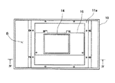
次に、上ケース10の構成について図2及び図4を参照して説明する。図2はデモンストレーションツールの上ケースを示す正面図であり、図4は図2におけるIV−IV線断面図である。
図2に示すように、上ケース10の略中央には液晶表示器14及び表示制御基板16が収容される。液晶表示器14及び表示制御基板16は、図4に示すように液晶表示器14の裏面に表示制御基板16が取付けられてユニット化され、表示制御基板16が上ケース10の底面に突設されたボスにネジ止めされることで上ケース10に固定されている。表示制御基板16は、CPU,ROM,RAM等を備え、メイン制御基板30から出力されるコマンドに応じて表示すべき図柄や画像等を適切に加工して液晶表示器14に表示する処理を行う。液晶表示器14は公知の装置であり、表示制御基板16から出力された画像信号に基づいてディスプレイに画像を表示する。液晶表示器14に表示される画像は、デモ対象機のセンター役物装置に表示される画像であり、例えば、デモ対象機において始動入賞口にパチンコ球が入賞した際にセンター役物装置に表示される特別図柄の変動(大当り遊技状態に移行するか否かを遊技者に認識させるために行われる)等が表示される。なお、本実施例においては、液晶表示器14及び表示制御基板16は、実際にデモ対象機に装備されるものがそのまま使用され、これによってコストの低減を図られている。
また、上ケース10には、図2に示されるように、上述の液晶表示器14及び表示制御基板16を囲むようにフレーム11aが設けられている。フレーム11aの上面には、図4に示されるように透明の保護プレート11bがネジ止めされ、保護プレート11bを介して液晶表示器14に表示される画像が視認可能となっている。なお、フレーム11aと上ケース10との間には隙間Bが形成されており(図4参照)、この隙間Bに電源コードAを収納可能としている。
【0018】
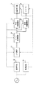
上述したように構成されるデモンストレーションツールにおける制御系の構成について図6を参照して簡単に説明する。図6は、本実施例に係るデモンストレーションツールの制御系の構成を示すブロック図である。図6に示すように、本実施例に係るデモンストレーションツールの制御系は、メイン制御基板30を中心に構成され、メイン制御基板30に表示制御基板16及び音声制御基板24が接続されて制御系が構成される。
メイン制御基板30は、入力装置31で選択されたコード番号に応じて表示制御基板16及び音声制御基板24に送信するコマンドを作成し、これらの作成したコマンドを表示制御基板16及び音声制御基板24に送信する処理を行う。表示制御基板16は、メイン制御基板30から送信されたコマンドを受信すると、表示制御プログラムに従って表示用データを適宜加工して、受信したコマンドに対応する画像信号を液晶表示器14に出力する。音声制御基板24は、メイン制御基板30から送信されたコマンドを受信すると、音声制御プログラムに従って音声用データを適宜加工して、受信したコマンドに対応する音声信号をスピーカー26に出力する。これによって、液晶表示器14には入力装置31で選択されたコード番号に対応する所定の画像が表示され、その液晶表示器14に表示される画像に対応した効果音がスピーカー26から出力されることとなる。
【0019】
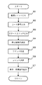
次に、上述したデモンストレーションツールを用いて液晶表示器14に所望の特別図柄の変動をデモンストレーションする場合の手順について図7に示すフローチャートを参照して説明する。図7は、デモンストレーションツールの動作手順を示すフローチャートである。
デモンストレーションツールにデモンストレーションを行わせるためには、まず、電源スイッチ20をONすることで液晶表示器14及びスピーカー26並びにメイン制御基板30,入力装置31,表示制御基板16及び音声制御基板24を動作可能状態とする(S01)。これにより、入力装置31の7セグ表示器32a,32bに現在選択されているコード番号が表示されることとなる。
各装置が動作可能状態となると、次にUPスイッチ34又はDOWNスイッチ36を操作することでコード番号を入力する(S02)。すなわち、操作者は液晶表示器14に表示させたい図柄演出(特別図柄の変動)に応じた番号を入力する。このように、本実施例のデモンストレーションツールでは、入力装置31でコード番号を入力することで、所望の特別図柄の変動(リーチアクション等)を選択できる。なお、このコード番号と特別図柄の変動パターンとを対応付ける対照表は予め作成されており、操作者はこの対照表を参照してコード番号を選択する。
コード番号が選択されると、次にスタートスイッチ38をONし(S03)、これによってデモンストレーションツールによるデモンストレーションが開始される。すなわち、スタートスイッチ38がONされることで、スタート信号がメイン制御基板30に出力され、これを契機にメイン制御基板30による処理(S04〜S06の処理)が開始される。
スタートスイッチ38がONされると、メイン制御基板30は、まず入力装置31で入力されたコード番号を読み込み、次いで、特別図柄の変動停止時の図柄(停止図柄)を決定する(S04)。すなわち、入力装置31で選択されたコード番号(変動パターン)から液晶表示器14に表示される特別図柄の変動が大当たりとなるかハズレとなるかが決定されているため、大当たりとなる場合には大当たりとなる停止図柄を決定し、ハズレとなる場合はハズレとなる停止図柄を決定する。停止図柄を決定する方法としては、公知のパチンコ機において行われる方法(乱数による抽選等)と同一の方法で行われる。
次に、メイン制御基板30はステップS02で入力されたコード番号と、ステップS04で決定された停止図柄に基づいて、表示制御基板16,音声制御基板24に送信するコマンドを作成する(S05)。具体的には、メイン制御基板30は、表示制御基板16に送信するコマンドとして変動パターンを指定するコマンド、特別図柄の停止図柄を指定するコマンド(左,中,右図柄の3つのコマンド)を作成し、音声制御基板24に送信するコマンドとして変動パターンに応じた効果音を指定するコマンドを作成する。
コマンドが作成されると、メイン制御基板30は、その作成したコマンドを表示制御基板16及び音声制御基板24に送信する(S06)。このステップS06の処理で送信されたコマンドが各制御基板16,24で受信されると、表示制御基板16はコマンドにより指定された特別図柄の変動を液晶表示器14に表示し、音声制御基板24はコマンドにより指定された効果音をスピーカー26から発生する(S07)。表示制御基板16及び音声制御基板24における処理は、実際のパチンコ機と同様の処理となる。すなわち、表示制御基板16及び音声制御基板24にデモ対象機に実際に装備されるものを使用していることから、これらの制御基板16,24における処理も実機と同様の処理となる。なお、他の特別図柄の変動を液晶表示器14に表示する場合には、再度図7のステップS02〜S07までの処理を繰り返せば良い。
【0020】
上述の説明から明らかなように、本実施例のデモンストレーションツールでは、入力装置31によって液晶表示器14に表示される画像(特別図柄の変動パターン)を選択することができるため、所望の画像(特別図柄の変動)を即座に表示することができる。
また、デモンストレーションツールに装備される図柄表示ユニット(液晶表示器14及び表示制御基板16)並びに音声ユニット(音声制御基板24及びスピーカー26)に実際のデモ対象機に用いられるものと同一のものを使用することで、デモンストレーションツールの製作コストの低減を図ると同時に、より実機に近いデモンストレーションが可能となっている。
また、デモンストレーションツールはケースに収容されて持ち運ぶことができ、さらに一般の家庭用電源(AC100V)を利用して動作するため、家庭用電源と接続できる場所であればデモンストレーションを行うことができる。
【0021】
【第2実施例】次に、本発明の第2実施例に係るデモンストレーションツールについて説明する。第2実施例に係るデモンストレーションツールは、第1実施例と同様に第1種パチンコ機用のデモンストレーションツールであって、その構成も第1実施例と略同一の構成を有する。ただし、第1実施例では液晶表示器及び表示制御基板が上ケース10内に収容されていたが、第2実施例ではこれらの装置が遊技盤に直接取付けられている点で異なる。以下、第1実施例と異なる部分を主に説明し、第1実施例と同一部分については同一の符合を付してその説明を省略する。
【0022】
図8に第2実施例の遊技機用デモンストレーションツールの外観が示されている。図8から明らかなように、第2実施例では、第1実施例の上ケース10の替わりに、デモ対象機に装備される遊技盤60(図8では一点鎖線で表示)がそのまま用いられている。なお、遊技盤60は、デモ対象機に装備されるものをそのまま用いる必要は必ずしも無く、運搬等を考慮して適宜大きさを調整することができる。
遊技盤60には遊技演出装置62が取付けられている。遊技演出装置62は、センター役物装置64(図8では図示を省略。ただし、図9,11に表示)と、センター役物装置64を制御する表示制御基板63(図8では図示を省略。ただし、図9,11に表示)で構成されている。表示制御基板63は、下ケース12内に収容されたメイン制御基板30とハーネス52によって接続される。ハーネス52の一端、詳しくは表示制御基板63側の端部にはコネクタ54が設けられている。コネクタ54は、表示制御基板63に設けられたコネクタ(図示省略)に着脱可能となっている。
したがって、コネクタ54が表示制御基板63のコネクタに挿し込まれると、メイン制御基板30と表示制御基板63が電気的に接続される。コネクタ54が表示制御基板63のコネクタに挿し込まれた状態が、図8中、一点鎖線で示されている。一方、コネクタ54を表示制御基板63のコネクタから抜き取ると、メイン制御基板30と表示制御基板63の電気的な接続が遮断される。コネクタ54が表示制御基板63のコネクタから抜き取られた状態が、図8中、実線で示されている。図8から明らかなように、この状態では、下ケース12と表示制御基板63とは電気的にも機械的にも接続されていないため、それぞれを個別に取扱うことができる。
【0023】
次に、図9を参照して遊技盤60に取付けられたセンター役物装置64について説明する。図9は遊技盤60の正面図である。図9に示すように、遊技盤60の略中央には開口部(図示せず)が形成されており、この開口部にセンター役物装置64が取付けられている。
センター役物装置64は、飾り枠65と、飾り枠65に遊技盤60の裏側から取り付けられた液晶表示器68とを備える。飾り枠65は、パトカーを模してデザインされており、その上部中央にはパトライトに似せた回転ライト66が組み込まれている。回転ライト66は、表示制御基板63からの駆動信号によって、その回転と点灯が制御される。このため、回転ライト66が点灯した状態で回転すると、あたかも、パトカーが警報灯を点灯・回転させているような印象を与えることができる。また、遊技盤60の表面には、センター役物装置64と関連する表示(本実施例では、パトカーに関連する絵)が描かれており、センター役物装置64と一体となってデザインされている。
飾り枠65によって囲まれる中央の開口部には、液晶表示器68の表示画面が位置するようになっている。したがって、液晶表示器68で表示される画像は飾り枠65の開口内に視認され、見る者は飾り枠65と液晶表示器68の画像を同時に視認することとなる。液晶表示器68の裏面には、表示制御基板63を収容する基板ボックス(図示省略)が取付けられている。表示制御基板63は、第1実施例と同様、メイン制御基板30からのコマンドに基づいて、液晶表示器68と回転ライト66を駆動する。
以上説明した遊技盤60と遊技演出装置62が請求項3でいう図柄表示ユニットに相当する。
【0024】
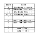
なお、第2実施例の下ケース12は第1実施例と同一構成を有するが、第2実施例では、コード番号とそのコード番号に対応する遊技演出との関係を示す「コード−遊技演出」表が印刷された銘板(本実施例ではシール)50が、保護プレート13上に貼り付けられている点で異なる。シール50は、図8に示すように、入力装置31の側方の保護プレート13上に貼り付けられている。したがって、操作者はシール50上に印刷された「コード−遊技演出」表を見ながら実行したい遊技演出のコード番号を入力できるので、コード番号の入力ミスを防止することができる。
図10にはシール50上に印刷されている「コード−遊技演出」表が示されている。図10に示されるように、シール50上には、コード番号と、そのコード番号に対応して実行される遊技演出の内容が印刷されている。例えば、入力装置31からコード番号として「0」が入力されると、センター役物装置64とスピーカ26が作動し、図柄表示器68にノーマル変動が表示されるとともにスピーカ26から効果音が出力される。また、入力装置31からコード番号として「4」が入力されると、図柄表示器68に特殊リーチ1の図柄変動が表示されるとともにスピーカ26から効果音が出力される。この際、図柄変動中の所定のタイミングでセンター役物装置64の回転ライト66が作動し、その回転と点灯が行われる。
【0025】
また、本実施例のデモンストレーションツールでは、上述のように図柄変動と連動して動作するのでは無く、図柄変動とは無関係にスピーカ26や回転ライト66のみを動作させることができる。例えば、コード番号「n1」,「n2」・・が入力されると、回転ライト66の点灯・回転のみが行われる。また、コード番号「n3」,「n4」・・が入力されると、スピーカ26からリーチ音のみが出力される。したがって、本実施例では、図柄変動とは別個に、回転ライト66の動作やスピーカ26からの効果音のみをデモンストレーションすることができる。
また、回転ライト66の回転・点灯の動作パターンが複数種類設けられているが、種類毎にコード番号が対応付けられているため、これらの動作パターンの違いを容易にデモンストレーションすることが可能となっている。すなわち、コード番号「n1」を入力すると回転ライト66は動作パターン1で動作し、コード番号「n2」を入力すると回転ライト66は動作パターン2で動作する。動作パターン1と動作パターン2で同一の図柄変動であっても信頼性(大当りになるか否かの確率)が異なるよう設定されている場合は、両者の相違を分かり易くデモンストレーションすることができる。同様に、スピーカ26から出力される効果音の相違についても、図柄変動とは無関係で、かつ、種類毎にデモンストレーションすることができる。
【0026】
図11には、第2実施例に係るデモンストレーションツールの制御系の構成を示している。図11から明らかなように、第2実施例のデモンストレーションツールの制御系は、第1実施例の制御系と略同一の構成を有している。ただし、第2実施例では、センター役物装置64に回転ライト66(すなわち、可動体を備えた電動役物装置)を備えているため、この回転ライト66を表示制御基板63が制御する点のみが異なる。
【0027】
次に、上述した第2実施例のデモンストレーションツールによって遊技演出をデモンストレーションする手順について、図12を参照して簡単に説明する。
図12に示すように操作者は、まず、電源スイッチ20をONして、液晶表示器68,回転ライト66及びスピーカー26等を動作可能状態とする(S10)。次に、シール50に印刷された「コード−遊技演出」表を参照しながら入力装置31からコード番号を入力し(S11)、スタートスイッチ38をONする(S12)。
【0028】
スタートスイッチ38がONされると、まず、メイン制御基板30は今回行う遊技演出がセンター役物装置64とスピーカ26を動作させるものか、回転ライト66のみを動作させるものか、スピーカ26のみを動作させるものかを判断する(S13)。具体的には、ステップS11で入力されたコード番号から判断する。例えば、コード番号が「2」であればセンター役物装置64とスピーカ26を動作させ、コード番号が「n1」であれば回転ライト66のみを動作させ、コード番号が「n3」であればスピーカ26のみを動作させると判断する。
【0029】
センター役物装置64とスピーカ26を動作させる場合は、上述した第1実施例と同様に処理を行う。すなわち、メイン制御基板30は、まず、停止図柄を決定し(S14)、ステップS11で入力されたコード番号とステップS14で決定された停止図柄から表示制御基板66と音声制御基板24に送信するコマンドを作成する(S15)。作成されたコマンドは表示制御基板66と音声制御基板24に送信され(S16)、コマンドを受信した各制御基板66,24はそのコマンドに基づいて処理を行う(S17)。すなわち、表示制御基板66は受信したコマンドで指定される図柄変動を液晶表示器68に表示し、特定のコード番号が入力されているときは回転ライト66を点灯・駆動させる。また、音声制御基板24は、受信したコマンドで指定される変動音をスピーカ26から出力する。
【0030】
一方、回転ライト66のみを動作させる場合は、メイン制御基板30は、ステップS11で入力されたコード番号から表示制御基板66に送信するコマンドのみを作成し(S18)、作成したコマンドを表示制御基板66に送信する(S19)。表示制御基板16は、メイン制御基板30から送信されたコマンドに基づいて回転ライト66を駆動する(S20)。
【0031】
また、スピーカ26のみを動作させる場合は、メイン制御基板30は、ステップS11で入力されたコード番号から音声制御基板24に送信するコマンドのみを作成し(S21)、作成したコマンドを音声制御基板24に送信する(S22)。音声制御基板24は、メイン制御基板30から送信されたコマンドに基づいてスピーカ26から効果音を出力する(S23)。
【0032】
上述の説明から明らかなように、第2実施例のデモンストレーションツールでは、下ケース12と遊技盤60とがハーネス52によってのみ接続される。したがって、デモンストレーション時に遊技盤の位置・向きをデモンストレーションを見せる相手の方向に容易に設定することができる。
また、ハーネス52のコネクタ54を表示制御基板63から抜き取れば、下ケース12と遊技盤60を別々に運搬等することができ、その取扱いを容易にすることができる。
さらに、デモ対象のパチンコ機に使用される遊技盤60をそのまま用いるため、より臨場感のあるデモンストレーションを行うことができる。
【0033】
以上、本発明の好適ないくつかの実施例について説明したが、本発明は上述した実施例に限られることなく、当業者の知識に基づいて種々の変更、改良を施した形態で実施することができる。
【0034】
例えば、上述した実施例では、図柄表示装置として液晶表示器(電気式表示器)を装備した例であったが、本発明はこのような形態に限らず、機械式表示器を装備するようにしても良い。機械式表示器には、例えば、表面に図柄が印刷されたドラムを回転させることで図柄を変動表示するドラム式表示器や、表面に図柄が印刷されたディスクを回転させることで図柄を変動表示するディスク式表示器が相当する。なお、デモ対象機に装備される機械式表示器が、図柄表示体(図柄が印刷されたドラムやディスク)の裏面に設けた発光体(ランプ等)の光によって図柄表示体に印刷された図柄の見え方に変化をつけるものである場合には、図柄表示体を照らす発光体を併せて装備するようにしても良い。
また、装備される図柄表示装置が電気式表示器であっても、上述した実施例に記載の液晶表示器のみならず、公知の他の電気式表示器(ドットLED、CRT、プラズマディスプレイ等)を装備するようにしても良い。さらには、デモ対象機の図柄表示装置が電気式表示器と機械式表示器を用いて図柄表示演出を行う場合等には、電気式表示器及び機械式表示器の両者を装備するようにしても良い。両者を装備することで、より実機に近い雰囲気を実現することができる。
【0035】
なお、上述した各実施例は本発明を第1種パチンコ機のデモンストレーションツールとして実現した例であったが、本発明はこの他にも、図柄表示装置を備えた各種遊技機、例えば、アレンジホール機(一定数の鋼球を遊技盤上に射出して所定の当たり状態を成立させるもの)、スロットマシン、雀球遊技機、パチスロ機等のデモンストレーションツールとすることもできる。
【0036】
また、本明細書または図面に説明した技術要素は、単独であるいは各種の組み合わせによって技術的有用性を発揮するものであり、出願時請求項記載の組み合わせに限定されるものではない。また、本明細書または図面に例示した技術は複数目的を同時に達成するものであり、そのうちの一つの目的を達成すること自体で技術的有用性を持つものである。
【図面の簡単な説明】
【図1】本発明の第1実施例に係るデモンストレーションツールの外観(ケースを開いた状態)を示す斜視図。
【図2】デモンストレーションツールの上ケースを示す正面図。
【図3】デモンストレーションツールの下ケースを示す正面図。
【図4】図2におけるIV‐IV線断面図。
【図5】図3におけるV‐V線断面図。
【図6】デモンストレーションツールの制御系の構成を示すブロック図。
【図7】デモンストレーションツールの動作手順を示すフローチャート。
【図8】本発明の第2実施例に係るデモンストレーションツールの外観を示す斜視図。
【図9】図8に示すデモンストレーションツールに装備される遊技盤の正面図。
【図10】図8に示すデモンストレーションツールの「コード番号−遊技演出」表を示す図。
【図11】図8に示すデモンストレーションツールの制御系の構成を示すブロック図。
【図12】図8に示すデモンストレーションツールの動作手順を示すフローチャート。
【符号の説明】
10・・上ケース
12・・下ケース
14・・液晶表示器
16・・表示制御基板
22,28・・電源基板
24・・音声制御基板
26・・スピーカ
30・・メイン制御基板
31・・入力装置
32・・7セグ表示器
34・・UPスイッチ
36・・DOWNスイッチ
38・・スタートスイッチ
40・・音声ボリューム[0001]
BACKGROUND OF THE
[0002]
2. Description of the Related Art For example, in a pachinko machine which is a kind of gaming machine, various symbol display effects are performed by a symbol display device mounted on the gaming machine body. In recent years, the symbol display effect performed by the symbol display device occupies most of the gaming interest of the player, and whether the symbol display effect is interesting determines the fun of the gaming machine. Therefore, in order to promote the sale of gaming machines, it is effective means to actually display and show the symbol display effects performed by the symbol display device (demonstration).
[0003]
However, in an actual gaming machine, a plurality of symbol display effects are prepared in advance in order to prevent the player from getting bored, and one of the symbol display effects is selected from the plurality of symbol display effects by random number drawing. Is selected at random and executed. For this reason, when trying to demonstrate a symbol display effect using an actual machine, it is necessary to execute a very large number of symbol display effects until a desired symbol display effect is displayed. Therefore, within a limited time for the demonstration, a desired symbol display effect may not be displayed.
[0004]
The present invention has been made in view of the above points, and an object of the present invention is to provide a demonstration tool for a gaming machine capable of efficiently performing a demonstration.
[0005]
Means for Solving the Problems, Functions and Effects In order to solve the above problems, an apparatus according to
In the gaming machine demonstration tool, when one symbol display effect is selected by the selection device, the selected symbol display effect is executed by the symbol display device. Therefore, the symbol display effect executed by the symbol display device can be directly selected, so that the demonstration can be efficiently performed. Further, since the symbol display device is detachable from the control device, both can be detached as needed. Therefore, handling during transportation to the demonstration site is improved.
[0006]
In some gaming machines, a symbol display effect is displayed in a display area provided on a gaming board. In such a gaming machine, the player visually recognizes the symbol display effect and the display (for example, a picture) drawn on the surface of the game board at the same time. Therefore, the display of the game board is often designed in association with the symbol display effect. In such a case, the demonstration can be efficiently performed by the device described in
That is, the apparatus according to
According to such a configuration, it is possible to simultaneously show the mounting portion formed on at least a part of the game board and the symbol display effect displayed on the symbol display device. For this reason, a demonstration can be performed more effectively.
Here, the "game board" is a member provided in the gaming machine and means a member provided with a display area in which a symbol display effect is displayed. For example, a pachinko machine corresponds to a game board equipped with a display for displaying a symbol display effect, and a slot machine includes a display window for displaying a part of a symbol row drawn on a drum device. Front panel.
[0007]
As the selection device, it is preferable that the operator can select a desired symbol display effect by a simple operation. Therefore, the selection device has code input means for inputting a code corresponding to each of the plurality of symbol display effects, and the control device displays the symbol display effect corresponding to the code input from the code input device. It is preferable to have the device execute it. According to such a configuration, the operator only needs to input a code, so that a desired symbol display effect can be selected by a simple operation.
In this case, it is preferable that a display unit for displaying a list of "code-symbol display effects" indicating a symbol display effect corresponding to the code is further provided for each code input by the code input means.
According to such a configuration, the operator can input a code while looking at the list of “code-symbol display effects” displayed on the display unit, so that a desired symbol display effect can be selected without error. it can.
As the “display unit” here, a display device capable of displaying various information, a nameplate (seal) on which a list of “code-design display effects” is printed, or the like can be used.
[0008]
Some gaming machines are equipped with an electric accessory device having a movable body that operates in conjunction with a symbol display device. In recent years, in this type of gaming machine, attempts have been made to make the symbol display effect more versatile by closely relating the symbol display effect to the operation of the movable body. Therefore, it is preferable that the demonstration tool for a gaming machine further include an electric accessory device having a movable body, and the control device activates the movable body in conjunction with the symbol display effect. According to such a configuration, the movable body moves in conjunction with the symbol display effect performed by the symbol display device, so that a more realistic demonstration can be performed.
In this case, it is preferable that the control device is programmed to operate only the movable body without performing the symbol display effect. If only the movable body can be operated, the movement of the movable body can be easily demonstrated.
Also, in the case of a gaming machine in which a plurality of types of operation patterns of the movable body are provided according to the symbol display effect, it is preferable that the operation pattern is programmed so that only the movable body can be operated for each type of the operation pattern. . According to such a configuration, it is possible to easily demonstrate the difference in the operation pattern of the movable body.
[0009]
In addition, a sound output device that generates a sound effect in conjunction with the symbol display device, or a demonstration tool for a gaming machine that includes a light emitting device that outputs the effect light, further includes a sound output device and / or light emitting device, It is preferable that the control device controls the audio output device and / or the light emitting device in conjunction with the symbol display effect performed by the symbol display device.
In this case, as in the case of the electric accessory device having the movable body, only the sound and / or the effect light is output from the sound output device and / or the light emitting device in a state where the symbol display effect is not performed. It is preferred that
[0010]
Further, the above problem can be solved by the device according to
The symbol display unit is programmed to execute a plurality of symbol display effects, and the control unit is programmed to cause the symbol display unit to execute one symbol display effect selected by the operator from the plurality of symbol display effects. ing. The symbol display unit and the control unit are separate and separable.
This demonstration tool also enables efficient demonstrations. Also, since the symbol display unit and the control unit are separate and separable, for example, the control unit is set near the person giving the presentation and the symbol display unit is set toward the customer. Handling becomes possible.
[0011]
DESCRIPTION OF THE PREFERRED EMBODIMENTS The demonstration tool for a game machine described in each of the above-mentioned claims can be suitably implemented by the following embodiments.
(Embodiment 1) It is preferable that the symbol display device is configured to include a display main body and a decorative member for decorating the periphery of the display main body. According to such an embodiment, the display device is closer to the actual device by the decorative member that decorates the periphery of the display main body, so that the demonstration effect can be enhanced.
(Mode 2) The control device includes a main control board and a display control board that controls the symbol display device based on a command output from the main control board, and the display control board is provided in an actual gaming machine. It is preferable that it is performed. According to such an embodiment, the configuration is the same as the configuration of the control device in the actual gaming machine, and it is possible to use the display control board actually provided in the gaming machine. Therefore, the manufacturing cost can be kept low.
(Embodiment 3) In
[0012]
First Embodiment An embodiment in which the present invention is implemented as a demonstration tool for a first-class pachinko machine will be described.
FIG. 1 is a perspective view showing the appearance of the demonstration tool according to the present embodiment (a state in which the case is opened (a state in which the demonstration is executed)). As shown in FIG. 1, a demonstration tool according to the present embodiment includes a
[0013]
First, the configuration of the
As shown in FIG. 3, in the
As shown in FIG. 5, the
[0014]
On the upper surface of the
The
[0015]
The
In the present embodiment, the sound unit of the
[0016]
The two
[0017]
Next, the configuration of the
As shown in FIG. 2, a
Further, as shown in FIG. 2, the
[0018]
The configuration of the control system in the demonstration tool configured as described above will be briefly described with reference to FIG. FIG. 6 is a block diagram illustrating a configuration of a control system of the demonstration tool according to the present embodiment. As shown in FIG. 6, the control system of the demonstration tool according to the present embodiment is configured around a
The
[0019]
Next, a procedure for demonstrating a change in a desired special symbol on the
In order to make the demonstration tool perform the demonstration, first, the
When each device is in an operable state, the code number is input by operating the
When the code number is selected, the
When the
Next, the
When the command is created, the
[0020]
As is clear from the above description, in the demonstration tool of the present embodiment, the image (special pattern variation pattern) displayed on the
In addition, the same symbol display unit (sound
In addition, since the demonstration tool can be carried in a case, and can be operated using a general household power supply (AC 100 V), a demonstration can be performed at a place where the demonstration tool can be connected to a household power supply.
[0021]
Second Embodiment Next, a demonstration tool according to a second embodiment of the present invention will be described. The demonstration tool according to the second embodiment is a demonstration tool for a first-type pachinko machine as in the first embodiment, and has the same configuration as that of the first embodiment. However, in the first embodiment, the liquid crystal display and the display control board are housed in the
[0022]
FIG. 8 shows the appearance of a demonstration tool for a gaming machine according to the second embodiment. As is clear from FIG. 8, in the second embodiment, instead of the
A
Therefore, when the connector 54 is inserted into the connector of the
[0023]
Next, the
The
The display screen of the
The
[0024]
Although the
FIG. 10 shows a “code-game effect” table printed on the
[0025]
Further, in the demonstration tool of the present embodiment, it is possible to operate only the
Also, a plurality of types of operation patterns for rotating and lighting the
[0026]
FIG. 11 illustrates a configuration of a control system of the demonstration tool according to the second embodiment. As is clear from FIG. 11, the control system of the demonstration tool of the second embodiment has substantially the same configuration as the control system of the first embodiment. However, in the second embodiment, since the
[0027]
Next, a procedure for demonstrating a game effect using the demonstration tool of the second embodiment will be briefly described with reference to FIG.
As shown in FIG. 12, the operator first turns on the
[0028]
When the
[0029]
When the
[0030]
On the other hand, when operating only the
[0031]
When only the
[0032]
As is clear from the above description, in the demonstration tool of the second embodiment, the
Further, if the connector 54 of the
Furthermore, since the
[0033]
Although some preferred embodiments of the present invention have been described above, the present invention is not limited to the above-described embodiments, and may be implemented in various modified and improved forms based on the knowledge of those skilled in the art. Can be.
[0034]
For example, in the above-described embodiment, a liquid crystal display (electric display) is provided as a symbol display device. However, the present invention is not limited to such a form, and a mechanical display may be provided. May be. The mechanical display, for example, a drum type display that changes the design by rotating the drum on which the pattern is printed on the surface, or a display that changes the design by rotating the disk with the design printed on the surface This corresponds to a disc display. The mechanical display mounted on the demonstration target machine is a symbol printed on the symbol display by the light of a luminous body (lamp, etc.) provided on the back of the symbol display (drum or disk on which the symbol is printed). In the case where the appearance of the image is changed, a light emitter for illuminating the symbol display may be additionally provided.
Also, even if the symbol display device to be equipped is an electric display, not only the liquid crystal display described in the above-described embodiment but also other known electric displays (dot LED, CRT, plasma display, etc.) May be equipped. Further, when the symbol display device of the demonstration target machine performs a symbol display effect using an electric display and a mechanical display, etc., it is necessary to equip both the electric display and the mechanical display. Is also good. By equipping both, an atmosphere closer to the actual machine can be realized.
[0035]
Each of the above-described embodiments is an example in which the present invention is implemented as a demonstration tool for a first-class pachinko machine. However, the present invention is also applicable to various other types of gaming machines having a symbol display device, such as an arrangement hall It can also be used as a demonstration tool such as a machine (one that injects a predetermined number of steel balls onto a game board to establish a predetermined contact state), a slot machine, a sparrow ball game machine, a pachislot machine, and the like.
[0036]
In addition, the technical elements described in the present specification or the drawings exhibit technical usefulness alone or in various combinations, and are not limited to the combinations described in the claims at the time of filing. The technology illustrated in the present specification or the drawings achieves a plurality of objects at the same time, and has technical utility by achieving one of the objects.
[Brief description of the drawings]
FIG. 1 is a perspective view showing the appearance (with a case opened) of a demonstration tool according to a first embodiment of the present invention.
FIG. 2 is a front view showing an upper case of a demonstration tool.
FIG. 3 is a front view showing a lower case of the demonstration tool.
FIG. 4 is a sectional view taken along line IV-IV in FIG. 2;
FIG. 5 is a sectional view taken along line VV in FIG. 3;
FIG. 6 is a block diagram showing a configuration of a control system of the demonstration tool.
FIG. 7 is a flowchart showing the operation procedure of the demonstration tool.
FIG. 8 is a perspective view showing the appearance of a demonstration tool according to a second embodiment of the present invention.
FIG. 9 is a front view of a game board provided in the demonstration tool shown in FIG. 8;
FIG. 10 is a view showing a “code number-game effect” table of the demonstration tool shown in FIG. 8;
FIG. 11 is a block diagram showing a configuration of a control system of the demonstration tool shown in FIG. 8;
FIG. 12 is a flowchart showing an operation procedure of the demonstration tool shown in FIG. 8;
[Explanation of symbols]
10. Upper case
12. Lower case
14. Liquid crystal display
16. Display control board
22, 28 ... Power supply board
24..Sound control board
26 Speaker
30..Main control board
31 ... Input device
32 7-segment display
34 UP switch
36 DOWN switch
38 Start switch
40 voice volume
Claims (3)
複数の図柄表示演出を実行可能な図柄表示装置と、
複数の図柄表示演出の中から1の図柄表示演出を選択するために操作者によって操作される選択装置と、
その選択装置で選択された図柄表示演出を図柄表示装置に実行させる制御装置とを有し、
図柄表示装置が制御装置に対し着脱可能に接続されていることを特徴とする遊技機用デモンストレーションツール。A demonstration tool for a gaming machine that randomly selects and executes one of a plurality of symbol display effects,
A symbol display device capable of executing a plurality of symbol display effects,
A selection device operated by an operator to select one symbol display effect from a plurality of symbol display effects;
Having a control device that causes the symbol display effect to be executed by the symbol display effect selected by the selection device,
A demonstration tool for a gaming machine, wherein a symbol display device is detachably connected to a control device.
前記図柄表示装置が取付けられる取付部が、前記遊技盤の少なくとも一部で形成されることを特徴とする遊技機用デモンストレーションツール。The demonstration tool according to claim 1, wherein the symbol display effect is displayed in a display area provided on the game board.
A demonstration tool for a gaming machine, wherein an attachment portion to which the symbol display device is attached is formed by at least a part of the game board.
図柄表示ユニットと制御ユニットとを備え、
図柄表示ユニットは、複数の図柄表示演出を実行可能にプログラムされ、
制御ユニットは、複数の図柄表示演出の中から操作者によって選択された1の図柄表示演出を図柄表示ユニットに実行させるようプログラムされ、
図柄表示ユニットと制御ユニットが別体で、かつ、分離可能となっていることを特徴とする遊技機用デモンストレーションツール。A demonstration tool for a gaming machine that randomly selects and executes one of a plurality of symbol display effects,
It has a symbol display unit and a control unit,
The symbol display unit is programmed to execute a plurality of symbol display effects,
The control unit is programmed to cause the symbol display unit to execute one symbol display effect selected by the operator from the plurality of symbol display effects,
A demonstration tool for a gaming machine, wherein the symbol display unit and the control unit are separate and separable.
Priority Applications (1)
| Application Number | Priority Date | Filing Date | Title |
|---|---|---|---|
| JP2002178959A JP2004016660A (en) | 2002-06-19 | 2002-06-19 | Demonstration tool for game machine |
Applications Claiming Priority (1)
| Application Number | Priority Date | Filing Date | Title |
|---|---|---|---|
| JP2002178959A JP2004016660A (en) | 2002-06-19 | 2002-06-19 | Demonstration tool for game machine |
Publications (1)
| Publication Number | Publication Date |
|---|---|
| JP2004016660A true JP2004016660A (en) | 2004-01-22 |
Family
ID=31176531
Family Applications (1)
| Application Number | Title | Priority Date | Filing Date |
|---|---|---|---|
| JP2002178959A Withdrawn JP2004016660A (en) | 2002-06-19 | 2002-06-19 | Demonstration tool for game machine |
Country Status (1)
| Country | Link |
|---|---|
| JP (1) | JP2004016660A (en) |
Cited By (9)
| Publication number | Priority date | Publication date | Assignee | Title |
|---|---|---|---|---|
| JP2006320359A (en) * | 2005-05-17 | 2006-11-30 | Newgin Corp | Portable type game machine presentation device |
| JP2006320360A (en) * | 2005-05-17 | 2006-11-30 | Newgin Corp | Portable type game machine presentation device |
| JP2007006993A (en) * | 2005-06-28 | 2007-01-18 | Newgin Corp | Carrier for pattern display device |
| JP2009172090A (en) * | 2008-01-23 | 2009-08-06 | Fujishoji Co Ltd | Game machine |
| USD880153S1 (en) * | 2018-01-10 | 2020-04-07 | Carl Zeiss Vision International Gmbh | Demonstration tool |
| JP2021151618A (en) * | 2017-02-28 | 2021-09-30 | 株式会社大一商会 | Game machine |
| JP2021151619A (en) * | 2017-02-28 | 2021-09-30 | 株式会社大一商会 | Game machine |
| JP2022027875A (en) * | 2017-06-22 | 2022-02-14 | 株式会社大一商会 | Game machine |
| JP2022079628A (en) * | 2017-01-27 | 2022-05-26 | 株式会社大一商会 | Game machine |
-
2002
- 2002-06-19 JP JP2002178959A patent/JP2004016660A/en not_active Withdrawn
Cited By (16)
| Publication number | Priority date | Publication date | Assignee | Title |
|---|---|---|---|---|
| JP2006320360A (en) * | 2005-05-17 | 2006-11-30 | Newgin Corp | Portable type game machine presentation device |
| JP4699087B2 (en) * | 2005-05-17 | 2011-06-08 | 株式会社ニューギン | Portable gaming machine presentation device |
| JP4699086B2 (en) * | 2005-05-17 | 2011-06-08 | 株式会社ニューギン | Portable gaming machine presentation device |
| JP2006320359A (en) * | 2005-05-17 | 2006-11-30 | Newgin Corp | Portable type game machine presentation device |
| JP2007006993A (en) * | 2005-06-28 | 2007-01-18 | Newgin Corp | Carrier for pattern display device |
| JP4705811B2 (en) * | 2005-06-28 | 2011-06-22 | 株式会社ニューギン | Symbol display carrier |
| JP2009172090A (en) * | 2008-01-23 | 2009-08-06 | Fujishoji Co Ltd | Game machine |
| JP2022079628A (en) * | 2017-01-27 | 2022-05-26 | 株式会社大一商会 | Game machine |
| JP7232483B2 (en) | 2017-01-27 | 2023-03-03 | 株式会社大一商会 | game machine |
| JP2021151618A (en) * | 2017-02-28 | 2021-09-30 | 株式会社大一商会 | Game machine |
| JP2021151619A (en) * | 2017-02-28 | 2021-09-30 | 株式会社大一商会 | Game machine |
| JP7184307B2 (en) | 2017-02-28 | 2022-12-06 | 株式会社大一商会 | game machine |
| JP7184306B2 (en) | 2017-02-28 | 2022-12-06 | 株式会社大一商会 | game machine |
| JP2022027875A (en) * | 2017-06-22 | 2022-02-14 | 株式会社大一商会 | Game machine |
| JP7317319B2 (en) | 2017-06-22 | 2023-07-31 | 株式会社大一商会 | game machine |
| USD880153S1 (en) * | 2018-01-10 | 2020-04-07 | Carl Zeiss Vision International Gmbh | Demonstration tool |
Similar Documents
| Publication | Publication Date | Title |
|---|---|---|
| JP5520396B1 (en) | Game machine | |
| JP2012105808A (en) | Game machine | |
| JP2009061023A (en) | Lower panel unit and slot machine | |
| JP2012110422A (en) | Game machine | |
| JP2004016660A (en) | Demonstration tool for game machine | |
| JP2007020688A (en) | Game machine | |
| JP2013039243A (en) | Pachinko game machine | |
| JP2003265769A (en) | Game machine | |
| JP2015157123A (en) | Game machine | |
| JP2011000391A (en) | Game machine | |
| JP2009261420A (en) | Game machine | |
| JP2007325877A (en) | Game machine | |
| JP2003275363A (en) | Game table | |
| JP2009225972A (en) | Pachinko game machine | |
| JP2005102802A (en) | Reel device and reel type game machine mounted with the same | |
| JP5880617B2 (en) | Game machine | |
| JPH1147345A (en) | Game stand | |
| JP5527496B2 (en) | Game machine | |
| JP2002204881A (en) | Demonstration tool for game machine | |
| JP2005124736A (en) | Rotary drum type game machine | |
| JP2008113912A (en) | Performance device in pinball game machine | |
| JP2002052127A (en) | Game machine | |
| JP2005176897A (en) | Game machine | |
| JP3064651U (en) | Display device of amusement machine using 7 color LED | |
| JP2002143369A (en) | Slot machine and pattern display method therefor |
Legal Events
| Date | Code | Title | Description |
|---|---|---|---|
| A621 | Written request for application examination |
Free format text: JAPANESE INTERMEDIATE CODE: A621 Effective date: 20050617 |
|
| A131 | Notification of reasons for refusal |
Free format text: JAPANESE INTERMEDIATE CODE: A131 Effective date: 20081118 |
|
| A761 | Written withdrawal of application |
Free format text: JAPANESE INTERMEDIATE CODE: A761 Effective date: 20081225 |