JP2004002205A - Chemical processing method of glass substrate - Google Patents
Chemical processing method of glass substrate Download PDFInfo
- Publication number
- JP2004002205A JP2004002205A JP2003324189A JP2003324189A JP2004002205A JP 2004002205 A JP2004002205 A JP 2004002205A JP 2003324189 A JP2003324189 A JP 2003324189A JP 2003324189 A JP2003324189 A JP 2003324189A JP 2004002205 A JP2004002205 A JP 2004002205A
- Authority
- JP
- Japan
- Prior art keywords
- chemical processing
- glass substrate
- processing
- liquid
- processing liquid
- Prior art date
- Legal status (The legal status is an assumption and is not a legal conclusion. Google has not performed a legal analysis and makes no representation as to the accuracy of the status listed.)
- Pending
Links
- 0 CC1CC(C)C(CC2)*CC2CCC1 Chemical compound CC1CC(C)C(CC2)*CC2CCC1 0.000 description 1
Images


Landscapes
- Liquid Crystal (AREA)
- Surface Treatment Of Glass (AREA)
Abstract
Description
本発明は、各種FPD(フラットパネルディスプレイ)用ガラス基板、例えばLCD(液晶ディスプレイ)用ガラス基板、PDP(プラズマディスプレイパネル)用ガラス基板、有機EL(エレクトロルミネッセンス)用ガラス基板等の1枚或いは一対の貼り合せ基板を加工するための化学加工方法に関する。 The present invention provides one or a pair of glass substrates for various FPDs (flat panel displays), such as glass substrates for LCDs (liquid crystal displays), glass substrates for PDPs (plasma display panels), and glass substrates for organic EL (electroluminescence). And a chemical processing method for processing the bonded substrate.
従来のガラス基板の加工方法には物理的な方法と化学的な方法がある。物理的な方法には、機械を用いた加工やブラストによる加工があり、化学的な方法にはウェットエッチングによる加工がある。最近では、以下に示すような品質改善が要求される趨勢にある。
1)ガラス基板に元々存在する表面キズを無くす。
2)パターニングされた薄膜を剥離した基板に残っているパターン跡を無くす。
3)ガラス基板の外表面の片側の全部を薄くし、その平坦性を高める。
4)ガラス基板の外表面の両側の全部を薄くし、その平坦性を高める。
5)ガラス基板の外表面の片側の一部に凹み部を作製し、各部の寸法と各面の平坦性を高める。
6)ガラス基板の外表面の両側の一部に凹み部を作製し、各部の寸法と各面の平坦性を高める。
7)3)〜6)のガラス基板を2枚の貼り合わせ基板と読み替えて、同じ目的のことを行なう。
Conventional glass substrate processing methods include a physical method and a chemical method. Physical methods include processing using a machine and processing by blast, and chemical methods include processing by wet etching. Recently, there has been a trend to require the following quality improvements.
1) Eliminate surface scratches originally present on the glass substrate.
2) Eliminate pattern traces remaining on the substrate from which the patterned thin film has been peeled off.
3) Thin the entire outer surface of the glass substrate on one side to enhance its flatness.
4) The entire outer surface of the glass substrate is thinned on both sides to enhance its flatness.
5) A recess is formed on one side of the outer surface of the glass substrate to enhance the dimensions of each part and the flatness of each surface.
6) Depressed portions are formed on both sides of the outer surface of the glass substrate to enhance the dimensions of each portion and the flatness of each surface.
7) The same purpose is performed by replacing the glass substrates 3) to 6) with two bonded substrates.
前記品質改善項目のうち、例えば1)〜4)に対して、従来の機械を用いた加工、例えば機械研磨では、平坦性の不足、割れや表面キズの発生、研磨模様の残留、研磨能力の限界等、避けられない課題が残る。一方、従来のウェットエッチングによる加工では、ガラス基板に初めから存在する表面キズ及びパターン跡を無くすのは困難であり、板厚を薄くする場合でも下記の例に示すように種々の問題が発生し、素ガラスと同等以上の品質を確保するのは困難であった。以降、代表例として液晶ガラス基板を対象として記述を進めていく。 Of the above-mentioned quality improvement items, for example, 1) to 4), processing using a conventional machine, for example, mechanical polishing, lacks flatness, generates cracks and surface scratches, leaves a polished pattern, and reduces polishing ability. Inevitable issues remain, such as limitations. On the other hand, in conventional processing by wet etching, it is difficult to eliminate surface scratches and pattern traces originally present on the glass substrate, and various problems occur even when the plate thickness is reduced as shown in the following example. However, it was difficult to secure the quality equal to or higher than that of elementary glass. Hereinafter, description will be made for a liquid crystal glass substrate as a representative example.
例えば、特許第2722798号公報には、液晶表示素子複数個分の面積を有する一対のガラス基板を各素子区画の液晶封入領域をそれぞれ囲むシール材を介して接着して素子集合体を組み立て、この素子集合体をフッ酸をベースとするエッチング液に浸漬して液晶ガラス基板の外面をエッチングする方法が開示されているが、板厚を薄くすることはできても後述する欠陥が生じるという問題がある。 For example, Japanese Patent No. 2722798 discloses that an element assembly is assembled by bonding a pair of glass substrates each having an area corresponding to a plurality of liquid crystal display elements via a sealing material surrounding a liquid crystal sealing area of each element section. A method is disclosed in which the element assembly is immersed in a hydrofluoric acid-based etchant to etch the outer surface of the liquid crystal glass substrate. However, even though the thickness can be reduced, the problem that defects described later occur will occur. is there.
また、特開2000-147474号公報には、フッ酸を含むエッチング溶液を貯溜するエッチング溶液槽の底部に気泡発生装置を備え、この気泡発生装置から発生した気泡によって前記エッチング溶液を攪拌して、エッチング溶液槽に入れたガラスの表面をエッチングする自動エッチング装置の発明が開示されているが、15〜17%のフッ酸を用いて液晶ガラス基板の外面を加工した場合、後述する欠陥が生じるという問題がある。 Also, Japanese Patent Application Laid-Open No. 2000-147474 has a bubble generator at the bottom of an etching solution tank for storing an etching solution containing hydrofluoric acid, and the etching solution is stirred by bubbles generated from the bubble generator. An invention of an automatic etching apparatus for etching the surface of glass placed in an etching solution tank is disclosed. However, when the outer surface of a liquid crystal glass substrate is processed using hydrofluoric acid of 15 to 17%, defects described later occur. There's a problem.
この発明においては、窒素ガス上昇気泡により加工液を攪拌させることによりガラス表面の均一な加工を実現しようとしているが、上昇した気泡と加工液とが液表面に達した後に下降する流れが上昇流の均一性を阻害するので、表面が均一に加工されないという問題がある。 In the present invention, an attempt is made to achieve uniform processing of the glass surface by agitating the processing liquid with nitrogen gas rising bubbles, but the flow of the rising bubbles and the processing liquid falling after reaching the liquid surface is an upward flow. There is a problem that the surface is not processed uniformly since the uniformity of the surface is hindered.
上述の2つの例に示した従来のウェットエッチングにより、50〜300μm加工した場合の問題点を以下に示す。
1)蛍光灯下でも確認できる白濁が発生する。
2)最大0.2mm径のピットが発生する。図14は加工後の表面粗度計により測定した結果を示したグラフである。
3)ピットの直径は加工量の増大とともに大きくなる。図15はピットの直径と加工量との関係を示したグラフである。
4)最大50個/cm2のピットが発生する。図16は単位面積当りのピット数と加工量との関係を示したグラフである。図16より単位面積当りのピット数は加工量の増大とともに増加することが判る。
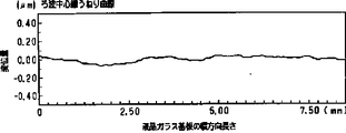
5)蛍光灯下で見えるウネリが発生する。図17は加工後の表面のウネリの状態を示したグラフである。
6)板厚の最大値と最小値との差が20〜100μmであり、不均一である。
7)加工前に人為的に付けた表面キズが加工により、幅も深さも大きくなる(図18及び19参照)。図18は加工前に意図的にキズを付けた表面の断面を示すグラフであり、図19は加工後の表面の断面を示すグラフである。
The problems when processing by 50 to 300 μm by the conventional wet etching shown in the above two examples will be described below.
1) White turbidity that can be confirmed even under a fluorescent lamp is generated.
2) A pit having a maximum diameter of 0.2 mm is generated. FIG. 14 is a graph showing a result measured by a surface roughness meter after processing.
3) The diameter of the pit increases as the amount of processing increases. FIG. 15 is a graph showing the relationship between the pit diameter and the processing amount.
4) A maximum of 50 pits /
5) Undulation visible under fluorescent light is generated. FIG. 17 is a graph showing the state of undulation on the surface after processing.
6) The difference between the maximum value and the minimum value of the plate thickness is 20 to 100 μm, which is non-uniform.
7) The width and depth of the surface flaws artificially formed before the processing are increased by the processing (see FIGS. 18 and 19). FIG. 18 is a graph showing a cross section of the surface intentionally scratched before processing, and FIG. 19 is a graph showing a cross section of the surface after processing.
また、例えば液晶ガラス基板にCrをスパッタリング後、カラーフィルター用画素をパターニングした場合、その基板が不良になったときには、通常、パターニングされたCrを剥離して機械研磨を行ない、パターン跡を消すことにより素ガラスとして再利用しているが、機械研磨に代えて従来のウェットエッチングを実施した場合はパターン跡が消えず、素ガラスとして再利用できないという問題があった。 Further, for example, when patterning pixels for a color filter after sputtering Cr on a liquid crystal glass substrate, when the substrate becomes defective, usually, the patterned Cr is peeled off and mechanical polishing is performed to eliminate pattern traces. However, when conventional wet etching is performed instead of mechanical polishing, there is a problem that pattern traces do not disappear and cannot be reused as raw glass.
本発明はかかる事情に鑑みてなされたものであり、板厚を薄くしつつ平坦性の高い各種FPD用ガラス基板を得ることができるガラス基板の化学加工方法を提供することを主たる目的とする。 The present invention has been made in view of such circumstances, and a main object of the present invention is to provide a method of chemically processing a glass substrate capable of obtaining various flat glass substrates with high flatness while reducing the thickness.
本発明のガラス基板の化学加工方法は、化学加工液中にガラス基板を浸漬して、このガラス基板の外表面を構成する片側の一部若しくは全部または両側の一部若しくは全部を0.5〜10μm/分の加工速度で加工することを特徴とする。 In the chemical processing method for a glass substrate of the present invention, a glass substrate is immersed in a chemical processing liquid, and a part or all of one side or a part or all of both sides constituting an outer surface of the glass substrate is 0.5 to 0.5%. It is characterized by processing at a processing speed of 10 μm / min.
また、上記の化学加工液としては、フッ酸、並びに塩酸、硫酸、リン酸、硝酸から選ばれる1種以上の無機酸を含有することが好ましい。また、他の好ましい化学加工液としては、フッ酸、並びに塩酸、硫酸、リン酸、硝酸から選ばれる1種以上の無機酸及び陰イオン系界面活性剤を含有するものを挙げることができる。 化学 Further, the chemical processing liquid preferably contains hydrofluoric acid and one or more inorganic acids selected from hydrochloric acid, sulfuric acid, phosphoric acid, and nitric acid. Other preferred chemical processing liquids include those containing hydrofluoric acid, one or more inorganic acids selected from hydrochloric acid, sulfuric acid, phosphoric acid, and nitric acid, and an anionic surfactant.
上記に詳述したように、本発明にかかる化学加工方法によれば、ガラス基板を化学加工することにより、板厚を薄くしつつ平坦性の高い各種FPD用ガラス基板を製造することができる。 As described above in detail, according to the chemical processing method according to the present invention, various flat glass substrates with high flatness can be manufactured by reducing the thickness of the glass substrate by chemically processing the glass substrate.
本発明は、素ガラス若しくは一旦各種FPD用ガラス基板として製造されたガラス基板(以下、まとめて「ガラス基板」という。)を加工対象とするものである。そして、本発明はこのようなガラス基板を化学加工液に浸漬して、ガラス基板の外表面の少なくとも片側の一部を特定条件の下で加工することにより、板厚を薄くするとともに表面の平坦性に優れた各種FPD用ガラス基板を提供しようとするものである。 The present invention is intended for processing raw glass or glass substrates once manufactured as glass substrates for various FPDs (hereinafter collectively referred to as “glass substrates”). In the present invention, such a glass substrate is immersed in a chemical processing solution, and at least one part of the outer surface of the glass substrate is processed under specific conditions, thereby reducing the thickness and flattening the surface. It is an object of the present invention to provide various FPD glass substrates having excellent properties.
本発明で用いる化学加工液は、ガラス基板の加工速度が0.5〜10μm/分の範囲にあることが好ましく、1.0〜5.0μm/分の範囲にあることが更に好ましい。本発明者の検討によれば、加工速度が10μm/分を上回ると平坦性に優れたガラス基板を製造することが困難となる。一方、加工速度が0.5μm/分を下回ると平坦性に優れたガラス基板を製造することはできるものの、製造速度が遅くなりすぎるため生産性の点から好ましくない。 化学 The chemical processing liquid used in the present invention preferably has a glass substrate processing speed in the range of 0.5 to 10 μm / min, more preferably 1.0 to 5.0 μm / min. According to the study of the present inventors, it becomes difficult to manufacture a glass substrate having excellent flatness when the processing speed exceeds 10 μm / min. On the other hand, if the processing speed is lower than 0.5 μm / min, a glass substrate having excellent flatness can be manufactured, but the manufacturing speed is too slow, which is not preferable from the viewpoint of productivity.
具体的には、加工速度が10μm/分を上回ると、加工後のガラス基板の表面にピット及びウネリが生じやすくなり、また板厚のバラツキが大きくなるのでガラス基板の平坦性が十分に確保できない。さらに、加工前から元々基板表面に存在したキズも残存してしまう。一方、加工速度が0.5〜10μm/分の範囲にある場合には、上記の問題点が解決されて平坦性に優れたガラス基板を製造することができる。 Specifically, when the processing speed exceeds 10 μm / min, pits and undulations are likely to occur on the surface of the processed glass substrate, and the thickness of the glass substrate varies greatly, so that the flatness of the glass substrate cannot be sufficiently ensured. . Further, the scratches originally present on the substrate surface before the processing remain. On the other hand, when the processing speed is in the range of 0.5 to 10 μm / min, the above problem is solved and a glass substrate having excellent flatness can be manufactured.
上記のような加工速度を得ることができれば、化学加工液の含有成分は特に限定されるものではないが、本発明に好ましい成分としては、フッ酸、ならびにフッ化アンモニウム、フッ化カリウム、フッ化ナトリウムから選ばれるフッ化物、塩酸、硫酸、リン酸、硝酸から選ばれる無機酸、酢酸、コハク酸から選ばれる有機酸、スルホン酸塩系界面活性剤等の陰イオン系界面活性剤、アミン系両性界面活性剤を挙げることができる。 If the processing speed as described above can be obtained, the components contained in the chemical processing liquid are not particularly limited, but preferred components of the present invention include hydrofluoric acid, and ammonium fluoride, potassium fluoride, and fluoride. Fluoride selected from sodium, inorganic acid selected from hydrochloric acid, sulfuric acid, phosphoric acid, nitric acid, organic acid selected from acetic acid and succinic acid, anionic surfactant such as sulfonate surfactant, amine-based amphoteric Surfactants can be mentioned.
上記成分のうち、フッ酸、フッ化物、無機酸及び有機酸は、ガラス基板を化学的に加工し、かつフッ化物等の反応生成物がガラス基板の表面に再付着するのを防止するために添加するものであり、陰イオン系界面活性剤とアミン系両性界面活性剤は、フッ化物等の反応生成物がガラス基板の表面に再付着するのを防止するために添加するものである。 Among the above components, hydrofluoric acid, fluoride, inorganic acid and organic acid are used to chemically process the glass substrate and to prevent reaction products such as fluoride from re-adhering to the surface of the glass substrate. The anionic surfactant and the amine amphoteric surfactant are added in order to prevent reaction products such as fluoride from re-adhering to the surface of the glass substrate.
本発明で用いる化学加工液は、フッ酸を必須成分とすること以外は任意の組み合わせが可能であり、使用するガラス基板の組成、必要とする加工速度、加工精度等に応じて各成分を適宜組み合わせることができる。本発明者の検討によれば、上記の各成分のうち、フッ酸と無機酸(特に塩酸と硝酸)の組み合わせ、フッ酸と陰イオン系界面活性剤の組み合わせ、フッ酸、有機酸(特に塩酸と硝酸)及び陰イオン系界面活性剤の組み合わせが特に好適に使用できることが確認されている。 The chemical processing liquid used in the present invention can be in any combination other than using hydrofluoric acid as an essential component, and each component is appropriately selected according to the composition of the glass substrate to be used, the required processing speed, the processing accuracy, and the like. Can be combined. According to the study of the present inventors, among the above components, a combination of hydrofluoric acid and an inorganic acid (particularly hydrochloric acid and nitric acid), a combination of hydrofluoric acid and an anionic surfactant, hydrofluoric acid, an organic acid (particularly hydrochloric acid) And nitric acid) and an anionic surfactant have been confirmed to be particularly suitable.
本発明では、上述した化学加工液中にガラス基板を浸漬することをその要旨とするものであるので、化学加工液を貯溜するための貯溜槽及びその周辺装置は特に限定されるものではない。例えば、化学加工液を貯溜した貯溜槽のみからなる化学加工装置を使用することもできる。この場合、ガラス基板の加工に際して、化学加工液中に珪フッ化物等の反応生成物が徐々に増加する結果、反応生成物がガラス基板の表面上に数多く付着してくるため、ガラス基板と化学加工液の固液反応速度がガラス基板上の各部分においてバラツキを生じやすくなり、ガラス基板の表面の平坦性を確保することが困難になることも想定される。しかし、事前の検討により化学加工液の品質が劣化する前に、化学加工液を新たなものと交換して使用することにより、本発明の主目的であるガラス基板表面の平坦性を十分確保することができる。 In the present invention, since the gist of the invention is to immerse the glass substrate in the above-described chemical processing liquid, the storage tank for storing the chemical processing liquid and its peripheral devices are not particularly limited. For example, a chemical processing apparatus including only a storage tank storing a chemical processing liquid may be used. In this case, when processing the glass substrate, a reaction product such as a silicon fluoride gradually increases in the chemical processing liquid, and as a result, many reaction products adhere to the surface of the glass substrate. It is also assumed that the solid-liquid reaction rate of the working liquid tends to vary in each part on the glass substrate, and it becomes difficult to secure the flatness of the surface of the glass substrate. However, before the quality of the chemical processing liquid is deteriorated by a prior study, the chemical processing liquid is replaced with a new one to use, thereby sufficiently securing the flatness of the glass substrate surface which is the main object of the present invention. be able to.
また、他の好ましい化学加工装置の例としては、化学加工中に反応生成物を含む化学加工液を化学加工液の貯溜槽から連続して取り除くとともに、新しい化学加工液を連続して供給することができる化学加工装置を挙げることができる。このような化学加工装置を採用した場合、加工後に生じた反応生成物が貯溜槽の外(反応系外)に取り除かれるとともに、常に有効成分のみを含む新鮮な化学加工液が貯溜槽内(反応系内)に供給されるので、ガラス基板表面の均一な化学加工が可能となる。 Another preferred example of the chemical processing apparatus is to continuously remove a chemical processing liquid containing a reaction product from a chemical processing liquid storage tank and continuously supply a new chemical processing liquid during chemical processing. And a chemical processing apparatus capable of producing the same. When such a chemical processing apparatus is employed, reaction products generated after processing are removed outside the storage tank (outside the reaction system), and fresh chemical processing liquid containing only active ingredients is always stored in the storage tank (reaction system). (In the system), it is possible to perform uniform chemical processing on the glass substrate surface.
また、本発明では、化学加工液がガラス基板の加工面に対して実質的に平行に近い液流を生じさせながら化学加工することが、ガラス基板の平坦性を向上させる上で好ましい。このことは、特に加工前に基板表面に微細な凹凸が多数存在する平坦性の低いガラス基板を加工した場合においてその効果が顕著に表れる。 In the present invention, it is preferable from the viewpoint of improving the flatness of the glass substrate to perform the chemical processing while generating a liquid flow substantially parallel to the processing surface of the glass substrate with the chemical processing liquid. This effect is remarkable particularly when a glass substrate having a low flatness, in which many fine irregularities are present on the substrate surface, is processed before the processing.
上記の作用効果は次のように説明することができる。本発明における化学加工方法は、ガラス基板(固体)と加工液(液体)との固液反応であり、(1)ガラス基板表面の近傍部分を構成する拡散層内への加工液の拡散、(2)加工成分のガラス基板表面への吸着、(3)加工成分とガラスとの化学反応、(4)反応生成物のガラス基板からの脱離、(5)拡散層外への反応生成物の拡散、等の多段階反応からなる。上記各反応の中で(2)〜(4)の反応速度は(1)と(5)の反応速度よりも大きいので、この多段階反応の全体としての反応速度は(1)と(5)の反応速度で決まるものであり、拡散律速となるものと考えられる。 The above operation and effect can be explained as follows. The chemical processing method in the present invention is a solid-liquid reaction between a glass substrate (solid) and a processing liquid (liquid), and (1) diffusion of the processing liquid into a diffusion layer constituting a portion near the surface of the glass substrate; 2) adsorption of the processing component on the glass substrate surface, (3) chemical reaction between the processing component and the glass, (4) desorption of the reaction product from the glass substrate, and (5) reaction product out of the diffusion layer. It consists of multi-step reactions such as diffusion. Since the reaction rates of (2) to (4) are higher than the reaction rates of (1) and (5) among the above reactions, the overall reaction rates of this multi-step reaction are (1) and (5). Is determined by the reaction rate, and is considered to be diffusion-controlled.
ここで、基板表面に微細な凹凸部分が存在する平坦性の低いガラス基板を用いて、ガラス基板の加工面に対して実質的に平行に近い化学加工液の液流を生じさせた場合、基板表面の凸部の方が凹部よりも液流の影響を強く受ける。すなわち、凸部においては、液流による一種の攪拌作用を受ける結果、拡散層の厚みが薄くなるので加工液の拡散速度が大きくなり、全体としての反応速度(すなわち加工速度)が大きくなる。一方、凹部では液流の影響をほとんど受けず、凹部近くの液流はよどんだ状態にあるので凹部近傍の拡散層の厚みはほとんど変化せず、全体としての反応速度が凸部に比べて小さくなる。 Here, when using a glass substrate with low flatness in which fine irregularities are present on the substrate surface and causing a flow of a chemical processing liquid substantially parallel to a processing surface of the glass substrate, The convex portions on the surface are more strongly affected by the liquid flow than the concave portions. That is, as a result of receiving a kind of agitating action by the liquid flow in the convex portion, the diffusion layer becomes thin, so that the diffusion speed of the processing liquid increases, and the overall reaction speed (that is, the processing speed) increases. On the other hand, the liquid flow is hardly affected in the concave portion, and the liquid flow near the concave portion is in a stagnant state, so the thickness of the diffusion layer near the concave portion hardly changes, and the overall reaction speed is smaller than that of the convex portion. Become.
ここで、例えば攪拌機等で加工液全体を攪拌して、ガラス基板を垂直に近い状態で浸漬した場合には、上昇液流が効果的に生じないので、ガラス基板の加工面に対して化学加工液の液流を実質的に平行にすることが困難となる。上昇液流を効果的に生じさせるためには、化学加工液の貯溜槽の最上部まで化学加工液を満たした状態で、加工液の下部から窒素ガス等の微細気泡を連続して発生させる方法を挙げることができる。そして、かかる加工液中にガラス基板を垂直に近い状態で浸漬することにより、化学加工液の上昇液流に対してガラス基板の加工面を実質的に平行にすることができる。 Here, for example, when the entire processing liquid is stirred by a stirrer or the like and the glass substrate is immersed in a nearly vertical state, the rising liquid flow does not effectively occur, and thus the chemical processing is performed on the processing surface of the glass substrate. It is difficult to make the liquid flows substantially parallel. In order to effectively generate the rising liquid flow, a method of continuously generating fine bubbles such as nitrogen gas from the lower part of the processing liquid while the chemical processing liquid is filled up to the top of the chemical processing liquid storage tank. Can be mentioned. Then, by immersing the glass substrate in such a processing liquid in a nearly vertical state, the processing surface of the glass substrate can be made substantially parallel to the rising liquid flow of the chemical processing liquid.
なお、本発明においてガラス基板の加工部分は、ガラス基板を構成する外表面のうち両側全部に限定されるものではなく、各種FPD用ガラス基板として要求される形態、例えば基板表面のパターニング形状等に応じて、必要とされる加工部分のみ適宜加工することができる。具体的には、例えば加工しない部分に耐酸性の保護膜を形成してマスキング処理を施し、加工後に保護膜を除去することにより、ガラス基板の片側面の一部若しくは全部またはガラス基板の両側の一部を化学加工することができる。 In the present invention, the processed portion of the glass substrate is not limited to all sides on the outer surface constituting the glass substrate, but may be in any form required for various FPD glass substrates, for example, in a patterning shape of the substrate surface. Accordingly, only necessary processing portions can be appropriately processed. Specifically, for example, by forming an acid-resistant protective film on a portion that is not processed, performing a masking process, and removing the protective film after processing, a part or all of one side of the glass substrate or both sides of the glass substrate. Some can be chemically processed.
以下では、上述した化学加工装置のうち後者の化学加工装置を用いてガラス基板を加工する実施形態について、図面を参照しつつ具体的に説明する。図1は、本発明の化学加工装置の一例を示す断面図である。化学加工装置1は化学加工液貯溜槽11を備えており、化学加工液貯溜槽11の底部には、ガスを導入して、多孔質からなる気泡吐出部12aから吐出すべくなしている気泡発生装置12が配置されており、気泡発生装置12の上側には、ガラス基板又は一対のガラス基板を貼り合わせたものを縦方向に挿入して保持するためのガラス基板収納治具18が配置されている。このガラス基板収納治具18は、ガラス基板収納治具用保持具17の中に配置されている。化学加工液貯溜槽11には、フッ酸を主成分とした化学加工液が投入される。
Hereinafter, an embodiment in which a glass substrate is processed using the latter chemical processing apparatus of the above-described chemical processing apparatuses will be specifically described with reference to the drawings. FIG. 1 is a sectional view showing an example of the chemical processing apparatus of the present invention. The
化学加工液貯溜槽11の周縁部には、化学加工液貯溜槽11から溢出させた前記化学加工液を受ける溢出液受け槽13が設けられており、溢出液受け槽13には、加工により生じた反応生成物を除去するためのフィルター14、及びこのフィルター14により濾過された化学加工液を再度化学加工液貯溜槽11に送るためのポンプ15が連結されている。そして、気泡発生装置12の下側に配され、ポンプ15により送り出された化学加工液を化学加工液貯溜槽の底部に向けて吐出するための多数の孔を有する化学加工液吐出部16aを備えた化学加工液吐出装置16により、再度、化学加工液が化学加工液貯溜槽11に供給される。
An overflow
また、化学加工装置1には、超音波振動子又は揺動攪拌翼を備えてもよい(図示せず)。これは、化学加工液貯溜槽11の全体に渡って気泡を拡散させるために用いるものである。
化学 Further, the
図2は、気泡発生装置12の一例を示す斜視図である。気泡発生装置12は、窒素ガス等のガスを導入するガス導入管12bと、ガス導入管12bに垂直に複数連結された、多孔質からなるパイプ状の気泡吐出部12a,12a,・・・とを備えている。また、図3は他の気泡発生装置12の気泡吐出部12aの一例を示す斜視図である。この気泡吐出部12aは多孔質からなり、板状を有している。図2及び図3ともに、気泡吐出部12aの孔径は10〜500μmにするのが好ましい。そして、これらの気泡発生装置12を液晶ガラス基板収納治具用保持具17の下側に配置して、微細気泡を上方に吐出させ、化学加工液を均一に上昇させる。この上昇液流により、ガラス基板の表面に常に新鮮な化学加工液を供給することができるとともに、フッ化物等の反応生成物がガラス基板の表面に再付着するのを防止することができる。
FIG. 2 is a perspective view showing an example of the
微細気泡の上昇液流が化学加工液の表面に達した後は、化学加工液貯溜槽11の周縁部から溢出し、溢出液受け槽13で受けられ、フィルター14を通した後、再度、化学加工液貯溜槽11に供給される。化学加工液を溢出させない場合、上昇液流が下降液流に転じる部分の断面積が小さいと、下降液流が上昇液流と交錯して均一な上昇液流が確保できなくなる。図4は、化学加工液貯溜槽11及びガラス基板収納治具用保持具17の一例を示す平面図である。図4に示したように、ガラス基板収納治具用保持具17の外側部分に相当する下降液流の通過断面積が、ガラス基板収納治具用保持具17の内側部分に相当する上昇液流の通過断面積の1〜3倍である場合、均一な上昇液流が確保できることが確認されている。
After the rising liquid flow of the fine bubbles reaches the surface of the chemical processing liquid, it overflows from the peripheral portion of the chemical processing
ガラス基板の成分と化学加工液とのフッ化物等の反応生成物は、微細気泡の上昇流によって上昇するが、これが化学加工液貯溜槽11内を循環して化学加工液貯溜槽11の底部に堆積すると、微細気泡の吐出に悪影響を及ぼすので、反応生成物の堆積を防止する必要がある。図5は、化学加工液吐出装置16の一例を示す斜視図である。この化学加工液吐出装置16には、多数の孔を有した化学加工液吐出部16aが複数、平行に設けられており、ポンプ15によって送り出された化学加工液を化学加工液吐出部16aから下向き又は斜め下向きに吐出させることにより、化学加工液の供給とともに、反応生成物の堆積を防止するように設計することが好ましい。
Reaction products such as fluorides between the components of the glass substrate and the chemical processing liquid rise due to the upward flow of fine bubbles, which circulate in the chemical processing
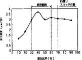
本発明では、上述した化学加工装置1を用いてガラス基板の加工速度を制御する方法として、化学加工液の組成の変更、化学加工液の温度の変更がある。図6は、化学加工液の添加比率と加工速度との関係を示すグラフである。この化学加工液は、フッ酸20重量部、塩酸20重量部及び硝酸20重量部からなる加工成分の水に対する添加比率を適宜変更した水溶液である。図6から、添加比率が10%では1.1μm/分であるが、添加比率が増加するにしたがって加工速度が増加し、40%で最大値の3.7μm/分を示し、その後少し低下して添加比率90%まで概略3μm/分とほぼ一定あることが判る。添加比率が30%以下では加工速度が遅く、また70%以上ではガラス表面に白曇が発生したり、ガラス表面に反応生成物のスラッジが付着するので、加工速度を制御するためには、添加比率を30〜60%にするのが好ましい。また、かかる関係は上述した他の加工成分の組合せからなる化学加工液を用いた場合であっても同様であることが確認されている。
In the present invention, as a method of controlling the processing speed of the glass substrate using the above-described
図7は、化学加工装置1を用いて、フッ酸5%と塩酸10%からなる化学加工液の加工速度と温度の関係を示したグラフである。このグラフの横軸は基準温度(30℃)からの偏移量であり、縦軸は加工速度である。図7から、温度の上昇にしたがって全体として加工速度は増加する傾向を示すが、基準温度(30℃)の±5℃の範囲では0.5μm/分の差しか生じないことが判る。このように、本発明においては、加工速度がほとんど変化しない温度領域が存在する。したがって、化学加工に当たっては事前に加工速度と温度の関係を調べ、加工速度がほとんど変化しない温度領域の中間温度を基準温度として、この中間温度付近で化学加工を行なうことにより、ガラス基板の加工速度を制御することが好ましい。また、加工速度がほとんど変化しない温度領域を事前に調べることにより、要求される加工精度に応じて加工時間の条件も緩やかに設定することができる。例えば、図7のグラフが得られた場合において、加工量のバラツキを20μmの範囲内に収めるには、加工時間のバラツキとして最大40分まで許されることになる。
FIG. 7 is a graph showing the relationship between the processing speed and the temperature of a chemical processing liquid composed of 5% hydrofluoric acid and 10% hydrochloric acid using the
以下に、本発明を実施例に基づき具体的に説明する。
[実施例1]上述した化学加工装置1を用いて、素ガラスの化学加工を行なった例を以下に示す。下記の素ガラスを所定の加工速度を有する化学加工液にそれぞれ浸漬し、同一の加工量を研磨した場合における加工速度とガラス基板の表面状態の関係を検討した。結果を表1に示す。
(1)素ガラスのサイズとそれぞれの目標の化学加工量
No.1;縦320mm×横400mm×厚み1.1mm。目標の化学加工量;0.3mm。
No.2;縦400mm×横500mm×厚み0.7mm。目標の化学加工量;0.2mm。
(2)化学加工液の組成
水を溶媒として、フッ酸、塩酸、硝酸を化学加工成分として、各成分の配合割合を適宜変更して加工速度が0.5、1.0、3.0、5.0、10.0、13.0、15.0(単位;μm/分)になる化学加工液を調製した。
Hereinafter, the present invention will be specifically described based on examples.
[Example 1] An example in which elementary glass was chemically processed using the above-described
(1) Size of raw glass and target amount of chemical processing
No.1; length 320mm x width 400mm x thickness 1.1mm. Target chemical processing amount: 0.3 mm.
No.2; length 400mm x width 500mm x thickness 0.7mm. Target chemical processing amount: 0.2mm.
(2) Composition of chemical processing liquid Using water as a solvent, hydrofluoric acid, hydrochloric acid, and nitric acid as chemical processing components, and changing the mixing ratio of each component as appropriate to change the processing speed to 0.5, 1.0, 3.0, 5.0, 10.0, 13.0, A chemical processing liquid having a concentration of 15.0 (unit: μm / min) was prepared.

表1において、ピット、ウネリ及び元キズの有無は、暗室のクリーンルーム内で蛍光灯下で目視により観察した結果を示したものである。また、図8は化学加工後におけるNo.2のガラス基板の板厚の測定位置を示したものである。表1に、図8に示した各位置において、超音波板厚計で板厚を測定し、バラツキとして最大値と最小値との差を求めた結果を示してある。ここで、小とは、バラツキが50μm以下、中とは、100〜200μm、大とは200μm以上であることをいう。表1の結果より、品質及び生産性の点から、加工速度は0.5〜10μm/分が好ましく、特に1.0〜5.0μm/分最適であることが判った。 In Table 1, the presence / absence of pits, undulations and scratches is the result of visual observation under a fluorescent lamp in a clean room in a dark room. FIG. 8 shows a measurement position of the thickness of the glass substrate No. 2 after the chemical processing. Table 1 shows the results obtained by measuring the thickness of each position shown in FIG. 8 with an ultrasonic thickness gauge and calculating the difference between the maximum value and the minimum value as a variation. Here, “small” means that the variation is 50 μm or less, “medium” means 100 to 200 μm, and “large” means 200 μm or more. From the results in Table 1, it was found that the processing speed was preferably 0.5 to 10 μm / min, and particularly 1.0 to 5.0 μm / min, in view of quality and productivity.
[実施例2]上述した化学加工装置1を用いて、素ガラスの化学加工を行なった例を以下に示す。
(1)素ガラスのサイズとそれぞれの目標の化学加工量
No.1;縦320mm×横400mm×厚み1.1mm。目標の化学加工量;0.3mm。
No.2;縦400mm×横500mm×厚み0.7mm。目標の化学加工量;0.2mm。
(2)化学加工液の組成
水を溶媒として、フッ酸5%、塩酸10%、硝酸5%を含有する化学加工液を使用した。
(3)素ガラスの受入検査と最終検査の方法
<板厚測定>
超音波式板厚計を用いて図8に示した測定位置の板厚を測定した。
<外観検査>
検査機器として蛍光灯(1500Lx以上)、集光灯(1万Lx以上)を使用し、検査機器の光源からガラス基板までの距離とガラス基板から測定者までの距離を共に300mmにして、ガラス基板に対する反射光と透過光を目視で確認した。
(4)実験結果
<加工速度>
素ガラスの片面に対して2.5μm/分であった。
<板厚>
表2に超音波板厚計によって測定した素ガラスの板厚を示した。
[Example 2] An example of performing chemical processing of elementary glass using the above-described
(1) Size of raw glass and target amount of chemical processing
No.1; length 320mm x width 400mm x thickness 1.1mm. Target chemical processing amount: 0.3 mm.
No.2; length 400mm x width 500mm x thickness 0.7mm. Target chemical processing amount: 0.2mm.
(2) Composition of chemical processing liquid A chemical processing liquid containing 5% of hydrofluoric acid, 10% of hydrochloric acid and 5% of nitric acid using water as a solvent was used.
(3) Method of acceptance inspection and final inspection of raw glass <Sheet thickness measurement>
The thickness at the measurement position shown in FIG. 8 was measured using an ultrasonic thickness gauge.
<Appearance inspection>
Fluorescent lamp (1500Lx or more) and condensing lamp (10,000Lx or more) are used as inspection equipment, and the distance from the light source of the inspection equipment to the glass substrate and the distance from the glass substrate to the operator are both 300mm. The reflected light and transmitted light with respect to were visually confirmed.
(4) Experimental results <Processing speed>
It was 2.5 μm / min for one side of the raw glass.
<Thickness>
Table 2 shows the thickness of the elemental glass measured by the ultrasonic thickness gauge.
<キズの有無>
図9に化学加工前後における素ガラスのキズの有無を検査した結果を示した。図9の結果より、化学加工前に存在したキズが化学加工により消失したことが判る。
<表面の平坦性>
No.2の素ガラスを化学加工した後の表面状態を測定した結果を図10に示した。表2及び図10より、素ガラスの各位置において、均一に目標量を加工することができ、素ガラスの表面が平坦化されたことが判る。
<Scratch>
FIG. 9 shows the results of inspection for the presence or absence of scratches on the elementary glass before and after the chemical processing. From the results in FIG. 9, it can be seen that the scratches existing before the chemical processing disappeared by the chemical processing.
<Surface flatness>
FIG. 10 shows the result of measuring the surface state after chemically processing No. 2 elementary glass. From Table 2 and FIG. 10, it can be seen that the target amount can be uniformly processed at each position of the raw glass, and the surface of the raw glass is flattened.
[実施例3]化学加工装置1を用いて、2枚の貼り合わせ液晶ガラス基板の化学加工を行なった例を示す。
(1)貼り合わせ液晶ガラス基板のサイズとそれぞれの目標の化学加工量
No.3;400mm×500mm×1.4mm。目標の化学加工量;両面合わせて0.4mm。
(2)化学加工液の組成
実施例2と同じ。
(3)受入検査と最終検査の方法
<板厚測定>
2枚の貼り合わせ液晶ガラス基板の表側の測定位置を図12に、裏側の測定位置を図13に示した。
<外観検査>
実施例2と同様に行なった。
(4)実験結果
<加工速度>
貼り合わせ液晶ガラス基板の片面に対して2.5μm/分であった。
<板厚>
表3に超音波板厚計によって測定した結果を示した。
[Example 3] An example of performing chemical processing on two bonded liquid crystal glass substrates using the
(1) Size of bonded liquid crystal glass substrate and target amount of chemical processing
No.3: 400mm x 500mm x 1.4mm. Target chemical processing amount: 0.4 mm for both sides.
(2) Composition of chemical processing liquid Same as Example 2.
(3) Acceptance inspection and final inspection method <Thickness measurement>
The measurement positions on the front side of the two bonded liquid crystal glass substrates are shown in FIG. 12, and the measurement positions on the back side are shown in FIG.
<Appearance inspection>
Performed in the same manner as in Example 2.
(4) Experimental results <Processing speed>
It was 2.5 μm / min for one side of the bonded liquid crystal glass substrate.
<Thickness>
Table 3 shows the results measured by the ultrasonic thickness gauge.
<キズの有無>
化学加工前後におけるキズの有無を検査した結果を図11に示した。図11より、化学加工前に存在したキズが化学加工により消失したことが判る。
<表面の平坦性>
表3から、貼り合わせガラス基板の各位置において、均一に目標量を加工することができ、表面が平坦化されていることが判る。
<Scratch>
FIG. 11 shows the results of inspection for the presence or absence of flaws before and after chemical processing. FIG. 11 shows that the scratches existing before the chemical processing disappeared by the chemical processing.
<Surface flatness>
From Table 3, it can be seen that the target amount can be uniformly processed at each position of the bonded glass substrate, and the surface is flattened.
[実施例4]カラーフィルター用画素がCrでパターニングされた液晶ガラス基板が不良になったので、Crを剥離した後、パターン跡を無くすため化学加工装置1により化学加工を行なった。
(1)Cr剥離後のガラス基板のサイズとそれぞれの目標の化学加工量
No.4;縦400mm×横500mm×厚み0.7mm。目標の化学加工量;5μm。
(2)化学加工液の組成
実施例2と同様のものを用いた。
(3)受入検査と最終検査の方法
<板厚測定>
超音波式板厚計を用いて図8に示した測定位置の板厚を測定した。
<外観検査>
実施例2と同様に行なった。
(4)実験結果
<加工速度>
ガラス基板の片面に対して2.5μm/分であった。
<板厚>
表4に超音波板厚計によって測定した結果を示した。
Example 4 The liquid crystal glass substrate in which the pixel for the color filter was patterned with Cr became defective. After the Cr was peeled off, chemical processing was performed by the
(1) Size of glass substrate after peeling Cr and target chemical processing amount
No.4: 400mm long x 500mm wide x 0.7mm thick. Target chemical processing amount: 5 μm.
(2) Composition of chemical processing liquid The same composition as in Example 2 was used.
(3) Acceptance inspection and final inspection method <Thickness measurement>
The thickness at the measurement position shown in FIG. 8 was measured using an ultrasonic thickness gauge.
<Appearance inspection>
Performed in the same manner as in Example 2.
(4) Experimental results <Processing speed>
It was 2.5 μm / min for one side of the glass substrate.
<Thickness>
Table 4 shows the results measured by an ultrasonic thickness gauge.
<パターン跡の有無>
パターン跡は化学加工により全て消失していることが確認された。
<表面の平坦性>
表4とパターン跡の消失結果から、液晶ガラス基板を均一に目標量加工することができ、表面が平坦化されたことが判る。
<Presence or absence of pattern marks>
It was confirmed that all the pattern traces had disappeared by the chemical processing.
<Surface flatness>
From Table 4 and the disappearance of the trace of the pattern, it can be seen that the target amount of the liquid crystal glass substrate could be uniformly processed and the surface was flattened.
以上のように本発明の化学加工方法を実施することにより、液晶ガラス基板の板厚を薄くしつつ、表面を平坦化できることが確認された。また、液晶ガラス基板の表面に初めから存在していたキズを消失させることができるのいでガラスの再利用が可能となる。さらに、本発明の化学加工方法においては、ガラス基板の大きさに関係なく生産性高くガラス基板の加工を実施することができる。なお、本実施例で使用した化学加工装置1は前記実施の形態において説明したものに限定されるものではなく、本発明の目的を損なわない限り種々の設計変更が可能である。
As described above, it was confirmed that by performing the chemical processing method of the present invention, the surface of the liquid crystal glass substrate could be flattened while reducing the thickness thereof. In addition, since the scratches originally present on the surface of the liquid crystal glass substrate can be eliminated, the glass can be reused. Further, in the chemical processing method of the present invention, it is possible to process a glass substrate with high productivity regardless of the size of the glass substrate. The
1 化学加工装置
11 化学加工液貯溜槽
12 気泡発生装置
12a 気泡吐出部
13 溢出液受け槽
14 フィルター
15 ポンプ
16 化学加工液吐出装置
17 ガラス基板収納治具用保持具
18 ガラス基板収納治具
DESCRIPTION OF
Claims (3)
2. The glass substrate according to claim 1, wherein the chemical processing liquid contains hydrofluoric acid, and at least one inorganic acid and an anionic surfactant selected from hydrochloric acid, sulfuric acid, phosphoric acid, and nitric acid. Chemical processing method.
Priority Applications (1)
| Application Number | Priority Date | Filing Date | Title |
|---|---|---|---|
| JP2003324189A JP2004002205A (en) | 2001-04-12 | 2003-09-17 | Chemical processing method of glass substrate |
Applications Claiming Priority (2)
| Application Number | Priority Date | Filing Date | Title |
|---|---|---|---|
| JP2001114498 | 2001-04-12 | ||
| JP2003324189A JP2004002205A (en) | 2001-04-12 | 2003-09-17 | Chemical processing method of glass substrate |
Related Parent Applications (1)
| Application Number | Title | Priority Date | Filing Date |
|---|---|---|---|
| JP2002110838A Division JP3523239B2 (en) | 2001-04-12 | 2002-04-12 | Glass substrate chemical processing method and glass substrate |
Related Child Applications (2)
| Application Number | Title | Priority Date | Filing Date |
|---|---|---|---|
| JP2005059895A Division JP2005239546A (en) | 2001-04-12 | 2005-03-04 | Chemical processing method for glass substrate |
| JP2005059892A Division JP2005247687A (en) | 2001-04-12 | 2005-03-04 | Chemical processing method of glass substrate |
Publications (2)
| Publication Number | Publication Date |
|---|---|
| JP2004002205A true JP2004002205A (en) | 2004-01-08 |
| JP2004002205A5 JP2004002205A5 (en) | 2005-08-04 |
Family
ID=30445675
Family Applications (1)
| Application Number | Title | Priority Date | Filing Date |
|---|---|---|---|
| JP2003324189A Pending JP2004002205A (en) | 2001-04-12 | 2003-09-17 | Chemical processing method of glass substrate |
Country Status (1)
| Country | Link |
|---|---|
| JP (1) | JP2004002205A (en) |
Cited By (4)
| Publication number | Priority date | Publication date | Assignee | Title |
|---|---|---|---|---|
| KR100677052B1 (en) | 2005-06-17 | 2007-02-02 | 테크노세미켐 주식회사 | Etching Composition for LCD Glass |
| JP2007240572A (en) * | 2006-03-06 | 2007-09-20 | Casio Comput Co Ltd | Manufacturing method of liquid crystal display device |
| JP2010191446A (en) * | 2010-03-19 | 2010-09-02 | Casio Computer Co Ltd | Method for manufacturing liquid crystal display |
| WO2019044757A1 (en) * | 2017-08-31 | 2019-03-07 | 日本電気硝子株式会社 | Method for etching glass, etching treatment device and glass sheet |
-
2003
- 2003-09-17 JP JP2003324189A patent/JP2004002205A/en active Pending
Cited By (7)
| Publication number | Priority date | Publication date | Assignee | Title |
|---|---|---|---|---|
| KR100677052B1 (en) | 2005-06-17 | 2007-02-02 | 테크노세미켐 주식회사 | Etching Composition for LCD Glass |
| JP2007240572A (en) * | 2006-03-06 | 2007-09-20 | Casio Comput Co Ltd | Manufacturing method of liquid crystal display device |
| JP2010191446A (en) * | 2010-03-19 | 2010-09-02 | Casio Computer Co Ltd | Method for manufacturing liquid crystal display |
| WO2019044757A1 (en) * | 2017-08-31 | 2019-03-07 | 日本電気硝子株式会社 | Method for etching glass, etching treatment device and glass sheet |
| JPWO2019044757A1 (en) * | 2017-08-31 | 2020-08-13 | 日本電気硝子株式会社 | Glass etching method, etching processing apparatus, and glass plate |
| US11174195B2 (en) | 2017-08-31 | 2021-11-16 | Nippon Electric Glass Co., Ltd. | Method for etching glass, etching treatment device and glass sheet |
| JP7173018B2 (en) | 2017-08-31 | 2022-11-16 | 日本電気硝子株式会社 | Glass etching method, etching processing apparatus, and glass plate |
Similar Documents
| Publication | Publication Date | Title |
|---|---|---|
| KR100380844B1 (en) | Method and apparatus for chemically polishing a liquid crystal glass substrate | |
| KR101838339B1 (en) | Method for making glass substrate for display, glass substrate and display panel | |
| JP3523239B2 (en) | Glass substrate chemical processing method and glass substrate | |
| KR101206923B1 (en) | Apparatus for cleaning single wafer | |
| JP3524540B2 (en) | Chemical processing method / chemical processing apparatus for glass substrate and glass substrate | |
| TW200837030A (en) | Substrate slimming apparatus and method of slimming substrate | |
| US20060144822A1 (en) | Apparatus and method for wet-etching | |
| US20160067749A1 (en) | Ultrasonic cleaning apparatus and method for cleaning | |
| JP2004002205A (en) | Chemical processing method of glass substrate | |
| TWI599547B (en) | Method of manufacturing glass substrate, glass substrate, and display panel | |
| JP2005247687A (en) | Chemical processing method of glass substrate | |
| JP2004099437A (en) | Method and apparatus for chemically processing glass substrate | |
| JP2005239546A (en) | Chemical processing method for glass substrate | |
| JP2007294596A (en) | Method and apparatus of etching manufacturing process of panel | |
| JP5902050B2 (en) | Display glass substrate manufacturing method and display glass substrate manufacturing apparatus | |
| JP2006315929A (en) | Method of polishing glass surface | |
| JP2009018973A (en) | Method and apparatus for treating surface | |
| TW201901146A (en) | Glass plate, method for inspecting end surface of glass plate, and method for manufacturing glass plate | |
| KR102166837B1 (en) | Method for producing glass substrate for display and apparatus for producing glass substrate for display | |
| CN213988841U (en) | Batch type wet etching equipment | |
| JP4455018B2 (en) | Frost treatment method for glass product surface | |
| WO2014091561A1 (en) | Method for renewing chemical solution used for device for etching liquid crystal glass, nozzle for chemical solution renewal, and chemical solution for renewal | |
| KR102350244B1 (en) | Apparatus for treating substrate and the method thereof and vibrator | |
| JP2007051017A (en) | Method of treating glass substrate for display and glass substrate for display treated by the method | |
| JPH06258608A (en) | Glass substrate cleaning and holding device |
Legal Events
| Date | Code | Title | Description |
|---|---|---|---|
| A521 | Written amendment |
Effective date: 20050304 Free format text: JAPANESE INTERMEDIATE CODE: A523 |
|
| A621 | Written request for application examination |
Effective date: 20050304 Free format text: JAPANESE INTERMEDIATE CODE: A621 |
|
| A871 | Explanation of circumstances concerning accelerated examination |
Free format text: JAPANESE INTERMEDIATE CODE: A871 Effective date: 20050304 |
|
| A975 | Report on accelerated examination |
Effective date: 20050420 Free format text: JAPANESE INTERMEDIATE CODE: A971005 |
|
| A131 | Notification of reasons for refusal |
Free format text: JAPANESE INTERMEDIATE CODE: A131 Effective date: 20050510 |
|
| A521 | Written amendment |
Effective date: 20050711 Free format text: JAPANESE INTERMEDIATE CODE: A523 |
|
| A02 | Decision of refusal |
Effective date: 20060207 Free format text: JAPANESE INTERMEDIATE CODE: A02 |
|
| A521 | Written amendment |
Free format text: JAPANESE INTERMEDIATE CODE: A523 Effective date: 20060407 |
|
| A911 | Transfer of reconsideration by examiner before appeal (zenchi) |
Free format text: JAPANESE INTERMEDIATE CODE: A911 Effective date: 20060425 |
|
| A912 | Removal of reconsideration by examiner before appeal (zenchi) |
Effective date: 20060623 Free format text: JAPANESE INTERMEDIATE CODE: A912 |