ES2698399T3 - Bags produced from open mesh material - Google Patents
Bags produced from open mesh material Download PDFInfo
- Publication number
- ES2698399T3 ES2698399T3 ES10771590T ES10771590T ES2698399T3 ES 2698399 T3 ES2698399 T3 ES 2698399T3 ES 10771590 T ES10771590 T ES 10771590T ES 10771590 T ES10771590 T ES 10771590T ES 2698399 T3 ES2698399 T3 ES 2698399T3
- Authority
- ES
- Spain
- Prior art keywords
- bag
- filaments
- open mesh
- seam
- mesh material
- Prior art date
- Legal status (The legal status is an assumption and is not a legal conclusion. Google has not performed a legal analysis and makes no representation as to the accuracy of the status listed.)
- Active
Links
- 239000000463 material Substances 0.000 title claims abstract description 418
- 239000002131 composite material Substances 0.000 claims abstract description 40
- 238000002844 melting Methods 0.000 claims abstract description 30
- 230000008018 melting Effects 0.000 claims abstract description 30
- 238000007789 sealing Methods 0.000 claims description 48
- 238000011049 filling Methods 0.000 claims description 37
- 239000004745 nonwoven fabric Substances 0.000 claims description 20
- 238000005304 joining Methods 0.000 claims description 15
- 230000001154 acute effect Effects 0.000 claims description 8
- 230000003014 reinforcing effect Effects 0.000 claims description 7
- 230000006835 compression Effects 0.000 claims description 4
- 238000007906 compression Methods 0.000 claims description 4
- 239000010410 layer Substances 0.000 description 135
- 239000004753 textile Substances 0.000 description 82
- 238000012360 testing method Methods 0.000 description 68
- 239000000758 substrate Substances 0.000 description 56
- 229920001903 high density polyethylene Polymers 0.000 description 38
- 239000004700 high-density polyethylene Substances 0.000 description 38
- 230000002787 reinforcement Effects 0.000 description 22
- 239000004744 fabric Substances 0.000 description 17
- 238000000034 method Methods 0.000 description 17
- 229920000092 linear low density polyethylene Polymers 0.000 description 12
- 239000004707 linear low-density polyethylene Substances 0.000 description 12
- 229920001684 low density polyethylene Polymers 0.000 description 11
- 239000004702 low-density polyethylene Substances 0.000 description 11
- 238000000605 extraction Methods 0.000 description 10
- 230000001965 increasing effect Effects 0.000 description 10
- 230000002829 reductive effect Effects 0.000 description 10
- OKTJSMMVPCPJKN-UHFFFAOYSA-N Carbon Chemical compound [C] OKTJSMMVPCPJKN-UHFFFAOYSA-N 0.000 description 9
- 229910052799 carbon Inorganic materials 0.000 description 9
- 238000009958 sewing Methods 0.000 description 9
- 230000015572 biosynthetic process Effects 0.000 description 8
- 238000010276 construction Methods 0.000 description 8
- 238000004519 manufacturing process Methods 0.000 description 8
- 239000000203 mixture Substances 0.000 description 8
- -1 polypropylene Polymers 0.000 description 7
- 239000000853 adhesive Substances 0.000 description 6
- 230000001070 adhesive effect Effects 0.000 description 6
- 230000014759 maintenance of location Effects 0.000 description 6
- 239000004743 Polypropylene Substances 0.000 description 5
- 238000006243 chemical reaction Methods 0.000 description 5
- 239000011162 core material Substances 0.000 description 5
- 230000000875 corresponding effect Effects 0.000 description 5
- 238000005520 cutting process Methods 0.000 description 5
- 229920001179 medium density polyethylene Polymers 0.000 description 5
- 239000004701 medium-density polyethylene Substances 0.000 description 5
- 229920001155 polypropylene Polymers 0.000 description 5
- 238000003860 storage Methods 0.000 description 5
- 239000012815 thermoplastic material Substances 0.000 description 5
- 238000012549 training Methods 0.000 description 5
- 238000009423 ventilation Methods 0.000 description 5
- 230000008901 benefit Effects 0.000 description 4
- 238000004806 packaging method and process Methods 0.000 description 4
- 229920000728 polyester Polymers 0.000 description 4
- 239000011324 bead Substances 0.000 description 3
- 239000010432 diamond Substances 0.000 description 3
- 238000010438 heat treatment Methods 0.000 description 3
- 238000009940 knitting Methods 0.000 description 3
- 238000003475 lamination Methods 0.000 description 3
- 238000012986 modification Methods 0.000 description 3
- 230000004048 modification Effects 0.000 description 3
- 229920000139 polyethylene terephthalate Polymers 0.000 description 3
- 230000008569 process Effects 0.000 description 3
- 239000002994 raw material Substances 0.000 description 3
- 239000013049 sediment Substances 0.000 description 3
- 238000000926 separation method Methods 0.000 description 3
- 229920003002 synthetic resin Polymers 0.000 description 3
- 239000000057 synthetic resin Substances 0.000 description 3
- 238000009864 tensile test Methods 0.000 description 3
- 238000010998 test method Methods 0.000 description 3
- 229920001169 thermoplastic Polymers 0.000 description 3
- 239000004416 thermosoftening plastic Substances 0.000 description 3
- 244000291564 Allium cepa Species 0.000 description 2
- 235000002732 Allium cepa var. cepa Nutrition 0.000 description 2
- 241000237519 Bivalvia Species 0.000 description 2
- 241000238557 Decapoda Species 0.000 description 2
- 229920010126 Linear Low Density Polyethylene (LLDPE) Polymers 0.000 description 2
- 241000237536 Mytilus edulis Species 0.000 description 2
- 244000046052 Phaseolus vulgaris Species 0.000 description 2
- 235000010627 Phaseolus vulgaris Nutrition 0.000 description 2
- 239000004698 Polyethylene Substances 0.000 description 2
- 244000061456 Solanum tuberosum Species 0.000 description 2
- 235000002595 Solanum tuberosum Nutrition 0.000 description 2
- 230000004888 barrier function Effects 0.000 description 2
- 238000005452 bending Methods 0.000 description 2
- 230000008859 change Effects 0.000 description 2
- 235000020639 clam Nutrition 0.000 description 2
- 235000009508 confectionery Nutrition 0.000 description 2
- 230000008602 contraction Effects 0.000 description 2
- 239000012792 core layer Substances 0.000 description 2
- 230000007423 decrease Effects 0.000 description 2
- 230000002708 enhancing effect Effects 0.000 description 2
- 238000005429 filling process Methods 0.000 description 2
- 235000013305 food Nutrition 0.000 description 2
- 230000004927 fusion Effects 0.000 description 2
- 230000000670 limiting effect Effects 0.000 description 2
- 235000020638 mussel Nutrition 0.000 description 2
- 229920000573 polyethylene Polymers 0.000 description 2
- 235000012015 potatoes Nutrition 0.000 description 2
- 238000003825 pressing Methods 0.000 description 2
- 238000007639 printing Methods 0.000 description 2
- 229920005989 resin Polymers 0.000 description 2
- 239000011347 resin Substances 0.000 description 2
- 230000000717 retained effect Effects 0.000 description 2
- 235000014102 seafood Nutrition 0.000 description 2
- 239000002356 single layer Substances 0.000 description 2
- 238000005303 weighing Methods 0.000 description 2
- 229920002799 BoPET Polymers 0.000 description 1
- 241001672694 Citrus reticulata Species 0.000 description 1
- 239000004677 Nylon Substances 0.000 description 1
- 229920002472 Starch Polymers 0.000 description 1
- 239000000654 additive Substances 0.000 description 1
- 230000000996 additive effect Effects 0.000 description 1
- 230000009286 beneficial effect Effects 0.000 description 1
- 238000009954 braiding Methods 0.000 description 1
- 229920002678 cellulose Polymers 0.000 description 1
- 239000001913 cellulose Substances 0.000 description 1
- 239000011248 coating agent Substances 0.000 description 1
- 238000000576 coating method Methods 0.000 description 1
- 239000003086 colorant Substances 0.000 description 1
- 230000002596 correlated effect Effects 0.000 description 1
- 230000003247 decreasing effect Effects 0.000 description 1
- 238000005538 encapsulation Methods 0.000 description 1
- 238000001125 extrusion Methods 0.000 description 1
- 239000004615 ingredient Substances 0.000 description 1
- 239000011229 interlayer Substances 0.000 description 1
- 239000005001 laminate film Substances 0.000 description 1
- 238000005259 measurement Methods 0.000 description 1
- 230000007246 mechanism Effects 0.000 description 1
- 239000000155 melt Substances 0.000 description 1
- 230000003278 mimic effect Effects 0.000 description 1
- 235000016709 nutrition Nutrition 0.000 description 1
- 229920001778 nylon Polymers 0.000 description 1
- 238000012858 packaging process Methods 0.000 description 1
- 238000002559 palpation Methods 0.000 description 1
- 230000036961 partial effect Effects 0.000 description 1
- 230000009467 reduction Effects 0.000 description 1
- 239000000565 sealant Substances 0.000 description 1
- 239000011257 shell material Substances 0.000 description 1
- 239000008107 starch Substances 0.000 description 1
- 235000019698 starch Nutrition 0.000 description 1
- 238000012345 traction test Methods 0.000 description 1
- 238000009941 weaving Methods 0.000 description 1
- 239000002759 woven fabric Substances 0.000 description 1
Classifications
-
- B—PERFORMING OPERATIONS; TRANSPORTING
- B65—CONVEYING; PACKING; STORING; HANDLING THIN OR FILAMENTARY MATERIAL
- B65B—MACHINES, APPARATUS OR DEVICES FOR, OR METHODS OF, PACKAGING ARTICLES OR MATERIALS; UNPACKING
- B65B51/00—Devices for, or methods of, sealing or securing package folds or closures; Devices for gathering or twisting wrappers, or necks of bags
- B65B51/10—Applying or generating heat or pressure or combinations thereof
- B65B51/26—Devices specially adapted for producing transverse or longitudinal seams in webs or tubes
- B65B51/30—Devices, e.g. jaws, for applying pressure and heat, e.g. for subdividing filled tubes
-
- B—PERFORMING OPERATIONS; TRANSPORTING
- B32—LAYERED PRODUCTS
- B32B—LAYERED PRODUCTS, i.e. PRODUCTS BUILT-UP OF STRATA OF FLAT OR NON-FLAT, e.g. CELLULAR OR HONEYCOMB, FORM
- B32B5/00—Layered products characterised by the non- homogeneity or physical structure, i.e. comprising a fibrous, filamentary, particulate or foam layer; Layered products characterised by having a layer differing constitutionally or physically in different parts
- B32B5/02—Layered products characterised by the non- homogeneity or physical structure, i.e. comprising a fibrous, filamentary, particulate or foam layer; Layered products characterised by having a layer differing constitutionally or physically in different parts characterised by structural features of a fibrous or filamentary layer
- B32B5/022—Non-woven fabric
-
- B—PERFORMING OPERATIONS; TRANSPORTING
- B32—LAYERED PRODUCTS
- B32B—LAYERED PRODUCTS, i.e. PRODUCTS BUILT-UP OF STRATA OF FLAT OR NON-FLAT, e.g. CELLULAR OR HONEYCOMB, FORM
- B32B5/00—Layered products characterised by the non- homogeneity or physical structure, i.e. comprising a fibrous, filamentary, particulate or foam layer; Layered products characterised by having a layer differing constitutionally or physically in different parts
- B32B5/02—Layered products characterised by the non- homogeneity or physical structure, i.e. comprising a fibrous, filamentary, particulate or foam layer; Layered products characterised by having a layer differing constitutionally or physically in different parts characterised by structural features of a fibrous or filamentary layer
- B32B5/06—Layered products characterised by the non- homogeneity or physical structure, i.e. comprising a fibrous, filamentary, particulate or foam layer; Layered products characterised by having a layer differing constitutionally or physically in different parts characterised by structural features of a fibrous or filamentary layer characterised by a fibrous or filamentary layer mechanically connected, e.g. by needling to another layer, e.g. of fibres, of paper
-
- B—PERFORMING OPERATIONS; TRANSPORTING
- B32—LAYERED PRODUCTS
- B32B—LAYERED PRODUCTS, i.e. PRODUCTS BUILT-UP OF STRATA OF FLAT OR NON-FLAT, e.g. CELLULAR OR HONEYCOMB, FORM
- B32B5/00—Layered products characterised by the non- homogeneity or physical structure, i.e. comprising a fibrous, filamentary, particulate or foam layer; Layered products characterised by having a layer differing constitutionally or physically in different parts
- B32B5/02—Layered products characterised by the non- homogeneity or physical structure, i.e. comprising a fibrous, filamentary, particulate or foam layer; Layered products characterised by having a layer differing constitutionally or physically in different parts characterised by structural features of a fibrous or filamentary layer
- B32B5/08—Layered products characterised by the non- homogeneity or physical structure, i.e. comprising a fibrous, filamentary, particulate or foam layer; Layered products characterised by having a layer differing constitutionally or physically in different parts characterised by structural features of a fibrous or filamentary layer the fibres or filaments of a layer being of different substances, e.g. conjugate fibres, mixture of different fibres
-
- B—PERFORMING OPERATIONS; TRANSPORTING
- B32—LAYERED PRODUCTS
- B32B—LAYERED PRODUCTS, i.e. PRODUCTS BUILT-UP OF STRATA OF FLAT OR NON-FLAT, e.g. CELLULAR OR HONEYCOMB, FORM
- B32B5/00—Layered products characterised by the non- homogeneity or physical structure, i.e. comprising a fibrous, filamentary, particulate or foam layer; Layered products characterised by having a layer differing constitutionally or physically in different parts
- B32B5/02—Layered products characterised by the non- homogeneity or physical structure, i.e. comprising a fibrous, filamentary, particulate or foam layer; Layered products characterised by having a layer differing constitutionally or physically in different parts characterised by structural features of a fibrous or filamentary layer
- B32B5/10—Layered products characterised by the non- homogeneity or physical structure, i.e. comprising a fibrous, filamentary, particulate or foam layer; Layered products characterised by having a layer differing constitutionally or physically in different parts characterised by structural features of a fibrous or filamentary layer characterised by a fibrous or filamentary layer reinforced with filaments
-
- B—PERFORMING OPERATIONS; TRANSPORTING
- B32—LAYERED PRODUCTS
- B32B—LAYERED PRODUCTS, i.e. PRODUCTS BUILT-UP OF STRATA OF FLAT OR NON-FLAT, e.g. CELLULAR OR HONEYCOMB, FORM
- B32B5/00—Layered products characterised by the non- homogeneity or physical structure, i.e. comprising a fibrous, filamentary, particulate or foam layer; Layered products characterised by having a layer differing constitutionally or physically in different parts
- B32B5/02—Layered products characterised by the non- homogeneity or physical structure, i.e. comprising a fibrous, filamentary, particulate or foam layer; Layered products characterised by having a layer differing constitutionally or physically in different parts characterised by structural features of a fibrous or filamentary layer
- B32B5/12—Layered products characterised by the non- homogeneity or physical structure, i.e. comprising a fibrous, filamentary, particulate or foam layer; Layered products characterised by having a layer differing constitutionally or physically in different parts characterised by structural features of a fibrous or filamentary layer characterised by the relative arrangement of fibres or filaments of different layers, e.g. the fibres or filaments being parallel or perpendicular to each other
-
- B—PERFORMING OPERATIONS; TRANSPORTING
- B32—LAYERED PRODUCTS
- B32B—LAYERED PRODUCTS, i.e. PRODUCTS BUILT-UP OF STRATA OF FLAT OR NON-FLAT, e.g. CELLULAR OR HONEYCOMB, FORM
- B32B5/00—Layered products characterised by the non- homogeneity or physical structure, i.e. comprising a fibrous, filamentary, particulate or foam layer; Layered products characterised by having a layer differing constitutionally or physically in different parts
- B32B5/22—Layered products characterised by the non- homogeneity or physical structure, i.e. comprising a fibrous, filamentary, particulate or foam layer; Layered products characterised by having a layer differing constitutionally or physically in different parts characterised by the presence of two or more layers which are next to each other and are fibrous, filamentary, formed of particles or foamed
- B32B5/24—Layered products characterised by the non- homogeneity or physical structure, i.e. comprising a fibrous, filamentary, particulate or foam layer; Layered products characterised by having a layer differing constitutionally or physically in different parts characterised by the presence of two or more layers which are next to each other and are fibrous, filamentary, formed of particles or foamed one layer being a fibrous or filamentary layer
- B32B5/26—Layered products characterised by the non- homogeneity or physical structure, i.e. comprising a fibrous, filamentary, particulate or foam layer; Layered products characterised by having a layer differing constitutionally or physically in different parts characterised by the presence of two or more layers which are next to each other and are fibrous, filamentary, formed of particles or foamed one layer being a fibrous or filamentary layer another layer next to it also being fibrous or filamentary
-
- B—PERFORMING OPERATIONS; TRANSPORTING
- B65—CONVEYING; PACKING; STORING; HANDLING THIN OR FILAMENTARY MATERIAL
- B65B—MACHINES, APPARATUS OR DEVICES FOR, OR METHODS OF, PACKAGING ARTICLES OR MATERIALS; UNPACKING
- B65B25/00—Packaging other articles presenting special problems
- B65B25/02—Packaging agricultural or horticultural products
- B65B25/04—Packaging fruit or vegetables
- B65B25/048—Packaging fruit or vegetables in nets
-
- B—PERFORMING OPERATIONS; TRANSPORTING
- B65—CONVEYING; PACKING; STORING; HANDLING THIN OR FILAMENTARY MATERIAL
- B65B—MACHINES, APPARATUS OR DEVICES FOR, OR METHODS OF, PACKAGING ARTICLES OR MATERIALS; UNPACKING
- B65B51/00—Devices for, or methods of, sealing or securing package folds or closures; Devices for gathering or twisting wrappers, or necks of bags
- B65B51/10—Applying or generating heat or pressure or combinations thereof
-
- B—PERFORMING OPERATIONS; TRANSPORTING
- B65—CONVEYING; PACKING; STORING; HANDLING THIN OR FILAMENTARY MATERIAL
- B65D—CONTAINERS FOR STORAGE OR TRANSPORT OF ARTICLES OR MATERIALS, e.g. BAGS, BARRELS, BOTTLES, BOXES, CANS, CARTONS, CRATES, DRUMS, JARS, TANKS, HOPPERS, FORWARDING CONTAINERS; ACCESSORIES, CLOSURES, OR FITTINGS THEREFOR; PACKAGING ELEMENTS; PACKAGES
- B65D29/00—Sacks or like containers made of fabrics; Flexible containers of open-work, e.g. net-like construction
-
- D—TEXTILES; PAPER
- D04—BRAIDING; LACE-MAKING; KNITTING; TRIMMINGS; NON-WOVEN FABRICS
- D04H—MAKING TEXTILE FABRICS, e.g. FROM FIBRES OR FILAMENTARY MATERIAL; FABRICS MADE BY SUCH PROCESSES OR APPARATUS, e.g. FELTS, NON-WOVEN FABRICS; COTTON-WOOL; WADDING ; NON-WOVEN FABRICS FROM STAPLE FIBRES, FILAMENTS OR YARNS, BONDED WITH AT LEAST ONE WEB-LIKE MATERIAL DURING THEIR CONSOLIDATION
- D04H3/00—Non-woven fabrics formed wholly or mainly of yarns or like filamentary material of substantial length
- D04H3/02—Non-woven fabrics formed wholly or mainly of yarns or like filamentary material of substantial length characterised by the method of forming fleeces or layers, e.g. reorientation of yarns or filaments
- D04H3/04—Non-woven fabrics formed wholly or mainly of yarns or like filamentary material of substantial length characterised by the method of forming fleeces or layers, e.g. reorientation of yarns or filaments in rectilinear paths, e.g. crossing at right angles
-
- D—TEXTILES; PAPER
- D04—BRAIDING; LACE-MAKING; KNITTING; TRIMMINGS; NON-WOVEN FABRICS
- D04H—MAKING TEXTILE FABRICS, e.g. FROM FIBRES OR FILAMENTARY MATERIAL; FABRICS MADE BY SUCH PROCESSES OR APPARATUS, e.g. FELTS, NON-WOVEN FABRICS; COTTON-WOOL; WADDING ; NON-WOVEN FABRICS FROM STAPLE FIBRES, FILAMENTS OR YARNS, BONDED WITH AT LEAST ONE WEB-LIKE MATERIAL DURING THEIR CONSOLIDATION
- D04H3/00—Non-woven fabrics formed wholly or mainly of yarns or like filamentary material of substantial length
- D04H3/08—Non-woven fabrics formed wholly or mainly of yarns or like filamentary material of substantial length characterised by the method of strengthening or consolidating
- D04H3/14—Non-woven fabrics formed wholly or mainly of yarns or like filamentary material of substantial length characterised by the method of strengthening or consolidating with bonds between thermoplastic yarns or filaments produced by welding
-
- B—PERFORMING OPERATIONS; TRANSPORTING
- B32—LAYERED PRODUCTS
- B32B—LAYERED PRODUCTS, i.e. PRODUCTS BUILT-UP OF STRATA OF FLAT OR NON-FLAT, e.g. CELLULAR OR HONEYCOMB, FORM
- B32B1/00—Layered products having a general shape other than plane
-
- B—PERFORMING OPERATIONS; TRANSPORTING
- B32—LAYERED PRODUCTS
- B32B—LAYERED PRODUCTS, i.e. PRODUCTS BUILT-UP OF STRATA OF FLAT OR NON-FLAT, e.g. CELLULAR OR HONEYCOMB, FORM
- B32B2250/00—Layers arrangement
- B32B2250/04—4 layers
-
- B—PERFORMING OPERATIONS; TRANSPORTING
- B32—LAYERED PRODUCTS
- B32B—LAYERED PRODUCTS, i.e. PRODUCTS BUILT-UP OF STRATA OF FLAT OR NON-FLAT, e.g. CELLULAR OR HONEYCOMB, FORM
- B32B2250/00—Layers arrangement
- B32B2250/20—All layers being fibrous or filamentary
-
- B—PERFORMING OPERATIONS; TRANSPORTING
- B32—LAYERED PRODUCTS
- B32B—LAYERED PRODUCTS, i.e. PRODUCTS BUILT-UP OF STRATA OF FLAT OR NON-FLAT, e.g. CELLULAR OR HONEYCOMB, FORM
- B32B2250/00—Layers arrangement
- B32B2250/24—All layers being polymeric
- B32B2250/242—All polymers belonging to those covered by group B32B27/32
-
- B—PERFORMING OPERATIONS; TRANSPORTING
- B32—LAYERED PRODUCTS
- B32B—LAYERED PRODUCTS, i.e. PRODUCTS BUILT-UP OF STRATA OF FLAT OR NON-FLAT, e.g. CELLULAR OR HONEYCOMB, FORM
- B32B2260/00—Layered product comprising an impregnated, embedded, or bonded layer wherein the layer comprises an impregnation, embedding, or binder material
- B32B2260/02—Composition of the impregnated, bonded or embedded layer
- B32B2260/021—Fibrous or filamentary layer
- B32B2260/023—Two or more layers
-
- B—PERFORMING OPERATIONS; TRANSPORTING
- B32—LAYERED PRODUCTS
- B32B—LAYERED PRODUCTS, i.e. PRODUCTS BUILT-UP OF STRATA OF FLAT OR NON-FLAT, e.g. CELLULAR OR HONEYCOMB, FORM
- B32B2262/00—Composition or structural features of fibres which form a fibrous or filamentary layer or are present as additives
- B32B2262/02—Synthetic macromolecular fibres
- B32B2262/0253—Polyolefin fibres
-
- B—PERFORMING OPERATIONS; TRANSPORTING
- B32—LAYERED PRODUCTS
- B32B—LAYERED PRODUCTS, i.e. PRODUCTS BUILT-UP OF STRATA OF FLAT OR NON-FLAT, e.g. CELLULAR OR HONEYCOMB, FORM
- B32B2262/00—Composition or structural features of fibres which form a fibrous or filamentary layer or are present as additives
- B32B2262/12—Conjugate fibres, e.g. core/sheath or side-by-side
-
- B—PERFORMING OPERATIONS; TRANSPORTING
- B32—LAYERED PRODUCTS
- B32B—LAYERED PRODUCTS, i.e. PRODUCTS BUILT-UP OF STRATA OF FLAT OR NON-FLAT, e.g. CELLULAR OR HONEYCOMB, FORM
- B32B2305/00—Condition, form or state of the layers or laminate
- B32B2305/38—Meshes, lattices or nets
-
- B—PERFORMING OPERATIONS; TRANSPORTING
- B32—LAYERED PRODUCTS
- B32B—LAYERED PRODUCTS, i.e. PRODUCTS BUILT-UP OF STRATA OF FLAT OR NON-FLAT, e.g. CELLULAR OR HONEYCOMB, FORM
- B32B2307/00—Properties of the layers or laminate
- B32B2307/50—Properties of the layers or laminate having particular mechanical properties
- B32B2307/582—Tearability
- B32B2307/5825—Tear resistant
-
- B—PERFORMING OPERATIONS; TRANSPORTING
- B32—LAYERED PRODUCTS
- B32B—LAYERED PRODUCTS, i.e. PRODUCTS BUILT-UP OF STRATA OF FLAT OR NON-FLAT, e.g. CELLULAR OR HONEYCOMB, FORM
- B32B2307/00—Properties of the layers or laminate
- B32B2307/70—Other properties
- B32B2307/718—Weight, e.g. weight per square meter
-
- B—PERFORMING OPERATIONS; TRANSPORTING
- B32—LAYERED PRODUCTS
- B32B—LAYERED PRODUCTS, i.e. PRODUCTS BUILT-UP OF STRATA OF FLAT OR NON-FLAT, e.g. CELLULAR OR HONEYCOMB, FORM
- B32B2323/00—Polyalkenes
- B32B2323/04—Polyethylene
- B32B2323/043—HDPE, i.e. high density polyethylene
-
- B—PERFORMING OPERATIONS; TRANSPORTING
- B32—LAYERED PRODUCTS
- B32B—LAYERED PRODUCTS, i.e. PRODUCTS BUILT-UP OF STRATA OF FLAT OR NON-FLAT, e.g. CELLULAR OR HONEYCOMB, FORM
- B32B2439/00—Containers; Receptacles
- B32B2439/02—Open containers
- B32B2439/06—Bags, sacks, sachets
-
- B—PERFORMING OPERATIONS; TRANSPORTING
- B32—LAYERED PRODUCTS
- B32B—LAYERED PRODUCTS, i.e. PRODUCTS BUILT-UP OF STRATA OF FLAT OR NON-FLAT, e.g. CELLULAR OR HONEYCOMB, FORM
- B32B2439/00—Containers; Receptacles
- B32B2439/40—Closed containers
- B32B2439/46—Bags
-
- Y—GENERAL TAGGING OF NEW TECHNOLOGICAL DEVELOPMENTS; GENERAL TAGGING OF CROSS-SECTIONAL TECHNOLOGIES SPANNING OVER SEVERAL SECTIONS OF THE IPC; TECHNICAL SUBJECTS COVERED BY FORMER USPC CROSS-REFERENCE ART COLLECTIONS [XRACs] AND DIGESTS
- Y10—TECHNICAL SUBJECTS COVERED BY FORMER USPC
- Y10T—TECHNICAL SUBJECTS COVERED BY FORMER US CLASSIFICATION
- Y10T428/00—Stock material or miscellaneous articles
- Y10T428/13—Hollow or container type article [e.g., tube, vase, etc.]
- Y10T428/1334—Nonself-supporting tubular film or bag [e.g., pouch, envelope, packet, etc.]
-
- Y—GENERAL TAGGING OF NEW TECHNOLOGICAL DEVELOPMENTS; GENERAL TAGGING OF CROSS-SECTIONAL TECHNOLOGIES SPANNING OVER SEVERAL SECTIONS OF THE IPC; TECHNICAL SUBJECTS COVERED BY FORMER USPC CROSS-REFERENCE ART COLLECTIONS [XRACs] AND DIGESTS
- Y10—TECHNICAL SUBJECTS COVERED BY FORMER USPC
- Y10T—TECHNICAL SUBJECTS COVERED BY FORMER US CLASSIFICATION
- Y10T428/00—Stock material or miscellaneous articles
- Y10T428/24—Structurally defined web or sheet [e.g., overall dimension, etc.]
- Y10T428/24058—Structurally defined web or sheet [e.g., overall dimension, etc.] including grain, strips, or filamentary elements in respective layers or components in angular relation
- Y10T428/24074—Strand or strand-portions
- Y10T428/24091—Strand or strand-portions with additional layer[s]
- Y10T428/24099—On each side of strands or strand-portions
-
- Y—GENERAL TAGGING OF NEW TECHNOLOGICAL DEVELOPMENTS; GENERAL TAGGING OF CROSS-SECTIONAL TECHNOLOGIES SPANNING OVER SEVERAL SECTIONS OF THE IPC; TECHNICAL SUBJECTS COVERED BY FORMER USPC CROSS-REFERENCE ART COLLECTIONS [XRACs] AND DIGESTS
- Y10—TECHNICAL SUBJECTS COVERED BY FORMER USPC
- Y10T—TECHNICAL SUBJECTS COVERED BY FORMER US CLASSIFICATION
- Y10T428/00—Stock material or miscellaneous articles
- Y10T428/24—Structurally defined web or sheet [e.g., overall dimension, etc.]
- Y10T428/24058—Structurally defined web or sheet [e.g., overall dimension, etc.] including grain, strips, or filamentary elements in respective layers or components in angular relation
- Y10T428/24124—Fibers
-
- Y—GENERAL TAGGING OF NEW TECHNOLOGICAL DEVELOPMENTS; GENERAL TAGGING OF CROSS-SECTIONAL TECHNOLOGIES SPANNING OVER SEVERAL SECTIONS OF THE IPC; TECHNICAL SUBJECTS COVERED BY FORMER USPC CROSS-REFERENCE ART COLLECTIONS [XRACs] AND DIGESTS
- Y10—TECHNICAL SUBJECTS COVERED BY FORMER USPC
- Y10T—TECHNICAL SUBJECTS COVERED BY FORMER US CLASSIFICATION
- Y10T442/00—Fabric [woven, knitted, or nonwoven textile or cloth, etc.]
- Y10T442/10—Scrim [e.g., open net or mesh, gauze, loose or open weave or knit, etc.]
- Y10T442/184—Nonwoven scrim
- Y10T442/186—Comprising a composite fiber
Abstract
Bolsa que tiene al menos un extremo cerrado y al menos paredes laterales primera y segunda, produciéndose al menos una porción de la bolsa a partir de un material de malla abierta que se extiende en las direcciones de la máquina y transversal a la máquina, comprendiendo el material de malla abierta: filamentos que se intersecan entre sí, siendo al menos algunos de los filamentos, filamentos compuestos que tienen un portador de un punto de fusión relativamente alto y una porción de unión de un punto de fusión relativamente bajo, uniéndose térmicamente la porción de unión de cada filamento compuesto a otros filamentos al menos en algunos puntos de intersección, en la que el material de malla abierta tiene una masa por área unitaria menor de 30 g/m2, preferiblemente menor de 20 g/m2, y una razón de resistencia con respecto a masa en al menos una de las direcciones de la máquina y transversal a la máquina de al menos 2,67 N/(g/m2), preferiblemente al menos 3,30 N/(g/m2), particularmente al menos 4,45 N/(g/m2), en la que se mide la resistencia según la norma ASTM D 5034.Bag having at least one closed end and at least first and second side walls, at least a portion of the bag being produced from an open mesh material extending in the machine directions and transverse to the machine, comprising the open mesh material: filaments intersecting with each other, at least some of the filaments being composite filaments having a relatively high melting point carrier and a relatively low melting point bonding portion, thermally bonding the portion bond of each composite filament to other filaments at least at some intersection points, where the open mesh material has a mass per unit area of less than 30 g / m2, preferably less than 20 g / m2, and a ratio of resistance to mass in at least one of the machine directions and transverse to the machine of at least 2.67 N / (g / m2), preferably at least 3.30 N / (g / m2), particularly at minus 4.45 N / (g / m2), where resistance is measured according to ASTM D 5034.
Description
DESCRIPCIÓNDESCRIPTION
Bolsas producidas a partir de material de malla abiertaBags produced from open mesh material
Antecedentes de la invenciónBACKGROUND OF THE INVENTION
Campo de la invenciónField of the invention
La invención se refiere a una bolsa producida a partir de un material de malla abierta y, más particularmente, se refiere a una bolsa producida a partir de un material de malla abierta formado a partir de filamentos, al menos algunos de los cuales son filamentos compuestos que pueden unirse térmicamente a otros filamentos al menos en algunos puntos de intersección. La invención se refiere adicionalmente a diversos tipos de bolsas producidas a partir de un material de este tipo y a métodos de producción de esas bolsas.The invention relates to a bag produced from an open mesh material and, more particularly, it relates to a bag produced from an open mesh material formed from filaments, at least some of which are composite filaments that can be thermally bonded to other filaments at least at some points of intersection. The invention further relates to various types of bags produced from a material of this type and to methods of producing those bags.
Descripción de la técnica relacionadaDescription of the related art
Se usan materiales de malla abierta sintéticos en una amplia variedad de aplicaciones, incluyendo bolsas, vallas de sedimentos y otras barreras, cubiertas para balas y pantallas. Estos materiales se forman con un patrón de malla abierta. Los materiales de malla tradicionales adoptaban la forma de hebras o filamentos que se cruzan que se tejían o tricotaban sin unir los filamentos en sus puntos de intersección. Más recientemente, se han introducido películas laminadas de manera cruzada sintéticas en las que se fijan entre sí capas adyacentes de hojas estiradas biaxialmente y cortadas a través de unión térmica en vez de a través de tejeduría o tricotado. Muchos de los materiales de malla abierta de la técnica anterior carecen de estabilidad dimensional. Es decir, se estiran de manera relativamente fácil de modo que, cuando se usan en aplicaciones tales como bolsas, se expanden o sobresalen de manera no deseada bajo el peso de los artículos en la bolsa. Estos materiales también tienden a ser relativamente débiles. Otros materiales ofrecen mejor estabilidad dimensional o resistencia pero son relativamente pesados en una base por área. Estos materiales de la técnica anterior también son relativamente caros de fabricar. Su gama de aplicaciones también es limitada debido a limitaciones sobre posibles variaciones de propiedades de materiales. Sumario de la invención Synthetic open mesh materials are used in a wide variety of applications, including bags, sediment fences and other barriers, bale covers and screens. These materials are formed with an open mesh pattern. Traditional mesh materials took the form of intersecting threads or filaments that were woven or knitted without joining the filaments at their points of intersection. More recently, synthetic cross laminated films have been introduced in which adjacent layers of biaxially stretched sheets are cut together and cut through thermal bonding rather than through weaving or knitting. Many of the open mesh materials of the prior art lack dimensional stability. That is, they are stretched relatively easily so that, when used in applications such as bags, they expand or protrude undesirably under the weight of the articles in the bag. These materials also tend to be relatively weak. Other materials offer better dimensional stability or strength but are relatively heavy on a per-area basis. These prior art materials are also relatively expensive to manufacture. Its range of applications is also limited due to limitations on possible variations in material properties. Summary of the invention
Según la invención, un material de malla abierta incluye filamentos que se intersecan entre sí, siendo al menos algunos de los filamentos, filamentos compuestos que tienen una porción de portador de un punto de fusión relativamente alto y una porción de unión de un punto de fusión relativamente bajo, uniéndose térmicamente la porción de unión de cada filamento compuesto a otros filamentos al menos en algunos puntos de intersección. El material de malla abierta tiene una masa por área unitaria menor de 30 g/m2 En otras realizaciones el material de malla abierta tiene una masa por área unitaria menor de 25 g/m2, menor de 20 g/m2, e incluso menor de 15 g/m2. El material de malla abierta puede extenderse en las direcciones de la máquina y transversal a la máquina y tener una razón de resistencia con respecto a masa en al menos una de las direcciones de la máquina y transversal a la máquina de al menos 2,67 N/(g/m2), en el que se mide la resistencia según la norma ASTM D 5034. En otras realizaciones, la razón de resistencia con respecto a masa puede superar los 3,30 N/(g/m2) o incluso 4,45 N/(g/m2). El material de malla abierta puede tener un alargamiento en porcentaje en al menos una de las direcciones de la máquina y transversal a la máquina de no más de aproximadamente el 50%, en el que se mide el alargamiento en porcentaje según la norma ASTm D 5034. En otras realizaciones, el alargamiento a la rotura puede ser de no más del 40% o no más del 30%.According to the invention, an open mesh material includes intersecting filaments, at least some of the filaments being composite filaments having a carrier portion of a relatively high melting point and a binding portion of a melting point. relatively low, the joining portion of each composite filament being thermally bonded to at least some other intersection points. The open mesh material has a mass per unit area of less than 30 g / m2. In other embodiments the open mesh material has a mass per unit area of less than 25 g / m2, less than 20 g / m2, and even less than 15 g / m2. g / m2. The open mesh material can extend in the directions of the machine and transverse to the machine and have a resistance ratio with respect to mass in at least one of the directions of the machine and transverse to the machine of at least 2.67 N / (g / m2), in which the strength is measured according to ASTM D 5034. In other embodiments, the strength ratio with respect to mass may exceed 3.30 N / (g / m2) or even 4, 45 N / (g / m2). The open mesh material can have an elongation in percentage in at least one of the directions of the machine and transverse to the machine of no more than about 50%, in which the elongation is measured in percentage according to ASTM D 5034 In other embodiments, the elongation at break can be no more than 40% or no more than 30%.
El material de malla abierta puede tener una masa por área unitaria menor de 20 g/m2 y una resistencia al estallido de al menos 80 kPa, en el que se mide la resistencia al estallido según la norma ASTM D 3786. En otras realizaciones, la resistencia al estallido puede superar los 100 kPa e incluso 150 kPa.The open mesh material can have a mass per unit area of less than 20 g / m2 and a burst strength of at least 80 kPa, in which the burst strength is measured according to ASTM D 3786. In other embodiments, the Burst resistance can exceed 100 kPa and even 150 kPa.
El material de malla abierta puede tener una resistencia al rasgado en los puntos de intersección de más de 10 N, en el que se establece la resistencia al rasgado en cuanto a la fuerza de rotura del material. En otras realizaciones, la resistencia al rasgado puede ser de más de 15 N e incluso más de 20 N.The open mesh material can have a tear resistance at intersection points of more than 10 N, in which the tear strength is established as to the breaking strength of the material. In other embodiments, the tear strength can be more than 15 N and even more than 20 N.
Aunque las características deseadas del material de malla abierta en cuanto a peso por área unitaria, razón de resistencia con respecto a masa, alargamiento en porcentaje, etc., puede variar dependiendo del uso final pretendido del material, el material de la presente divulgación tiene una baja masa por área unitaria y una alta razón de resistencia con respecto a masa mientras que mantiene buena estabilidad dimensional. Esta baja masa por área unitaria y alta razón de resistencia con respecto a masa del material reduce la huella de carbono asociada con la fabricación, el transporte y la eliminación de productos producidos a partir del material, tal como bolsas para productos agrícolas, porque los productos requieren menos materias primas y ocupan menos volumen. Por tanto, requieren menos energía para su producción y manipulación que los productos producidos a partir de materiales tradicionales.Although the desired characteristics of the open mesh material in terms of weight per unit area, strength ratio with respect to mass, elongation in percentage, etc., may vary depending on the intended end use of the material, the material of the present disclosure has a low mass per unit area and a high resistance ratio with respect to mass while maintaining good dimensional stability. This low mass per unit area and high strength ratio with respect to material mass reduces the carbon footprint associated with the manufacture, transport and disposal of products produced from the material, such as bags for agricultural products, because the products they require less raw materials and occupy less volume. Therefore, they require less energy for their production and handling than products produced from traditional materials.
En una configuración, el material es un material textil no tejido que contiene al menos dos capas de filamentos de trama que pueden estar bordeadas en uno o ambos lados por una capa de filamentos de urdimbre. Los filamentos de trama se cruzan entre sí formando un ángulo agudo para formar un patrón generalmente en forma de rombo. Los filamentos de urdimbre se extienden formando un ángulo agudo con respecto a los filamentos que se cruzan y en paralelo entre sí y pueden extenderse en paralelo a la dirección de la máquina. Los filamentos de urdimbre, y posiblemente los filamentos de trama también, son filamentos compuestos que pueden unirse térmicamente. Pueden proporcionarse capas adicionales, tales como capas de urdimbre y/o trama adicionales, un cordón ajustable u otro mecanismo de cierre, una estructura tal como una etiqueta, y/o una o más hojas de laminación o refuerzo en una o ambas superficies del material textil. En una variante de esta configuración, podrían omitirse ambas capas de los filamentos de urdimbre de tal manera que el material textil se forma a partir de los filamentos de trama que se cruzan.In one configuration, the material is a non-woven fabric containing at least two layers of weft filaments that may be bordered on one or both sides by a layer of warp filaments. The filaments They intersect each other at an acute angle to form a generally diamond-shaped pattern. The warp filaments extend at an acute angle with respect to the intersecting filaments and parallel to each other and may extend parallel to the machine direction. The warp filaments, and possibly the weft filaments as well, are composite filaments that can be thermally bonded. Additional layers, such as additional warp and / or weft layers, an adjustable drawstring or other closure mechanism, a structure such as a label, and / or one or more sheets of lamination or reinforcement on one or both surfaces of the material may be provided. textile. In a variant of this configuration, both layers of the warp filaments could be omitted in such a way that the textile material is formed from the intersecting weft filaments.
Pueden producirse muchos artículos al menos en parte a partir de estos materiales textiles, incluyendo vallas de sedimentos, barreras luminosas y bolsas para contener productos agrícolas y otros artículos. Tales bolsas incluyen bolsas de costura en L, bolsas de formación, llenado y sellado (FFS) y bolsas multisustrato tales como bolsas HALF Y HALF®.Many items can be produced at least in part from these textiles, including sediment fences, light barriers and bags for holding agricultural products and other items. Such bags include L-seam bags, training, filling and sealing bags (FFS) and multi-substrate bags such as HALF and HALF® bags.
En el caso de una bolsa de costura en L, podría formarse un material de malla abierta que tiene al menos algunas de las características descritas anteriormente para incluir un extremo cerrado, un extremo abierto, al menos una costura lateral en un lado de la misma, y una costura en el extremo cerrado de la misma. Las costuras laterales y de extremo pueden formarse mediante cosido para producir una “bolsa cosida en L”. El extremo abierto puede incluir una porción texturizada. La porción texturizada, si está presente, puede incluir una banda que se une al material textil o un filamento de texturización dispuesto alrededor del extremo abierto.In the case of an L-seam bag, an open mesh material having at least some of the features described above could be formed to include a closed end, an open end, at least a side seam on one side thereof, and a seam at the closed end thereof. The side and end seams can be formed by stitching to produce an "L-stitched bag". The open end may include a textured portion. The textured portion, if present, may include a band that attaches to the textile material or a texturizing filament disposed around the open end.
Una bolsa de costura en L que tiene algunas o todas las características de la bolsa de costura en L comentada anteriormente puede ser lo suficientemente delgada y compresible como para que, cuando una pluralidad de las bolsas se apilan en un apilamiento y se someten a una fuerza de 267 kN, el apilamiento contiene al menos 25 bolsas/cm. En otras realizaciones, el apilamiento contiene más de 30 bolsas/cm e incluso más de 35 bolsas/cm. La invención se refiere a una denominada bolsa de formación, llenado y sellado. La bolsa según este aspecto tiene lados opuestos primero y segundo, cada uno de los cuales se forma al menos en parte a partir de una tira de un material de hoja y al menos en parte a partir de un material de malla abierta. El material de hoja puede ser, por ejemplo, un material de película producido al menos en parte a partir de película termoplástica y que se extiende a lo largo desde al menos un extremo la bolsa. Una costura de extremo se extiende a través de un extremo de la bolsa y une entre sí las tiras primera y segunda de material de hoja con al menos una capa del material de malla abierta entre las mismas. La costura de extremo se forma a partir de una costura que tiene una resistencia de al menos 2,5 N. Puede proporcionarse la bolsa de formación, llenado y sellado que tiene extremos superior e inferior, cerrándose al menos el extremo inferior. Un cuerpo se extiende entre los extremos superior e inferior para definir un volumen interior que contiene artículos. El cuerpo de la bolsa llena tiene al menos una forma de la sección en corte transversal generalmente poligonal a lo largo de al menos la mayor parte de su longitud. El cuerpo tiene al menos dos lados opuestos formados a partir de un material de malla abierta que tiene una masa por área unitaria de no más de 30 g/m2. La bolsa tiene una altura inicial medida desde el extremo inferior hasta el extremo superior después de sellarse el extremo inferior y después de formarse el cuerpo se forma pero antes de colocarse los artículos en la bolsa y antes de sellar el extremo superior. La bolsa tiene además una altura final que se mide después de colocarse los artículos en la bolsa y después de colocarse la bolsa sobre una superficie horizontal y dejarse sin apoyo desde arriba. La altura final de la bolsa es al menos el 35% de la altura inicial.An L-seam bag having some or all of the features of the L-seam bag discussed above may be thin and compressible enough so that when a plurality of the bags are stacked in a stack and subjected to a force of 267 kN, the stack contains at least 25 bags / cm. In other embodiments, the stack contains more than 30 bags / cm and even more than 35 bags / cm. The invention relates to a so-called bag for forming, filling and sealing. The bag according to this aspect has opposite sides first and second, each of which is formed at least in part from a strip of a sheet material and at least in part from an open mesh material. The sheet material can be, for example, a film material produced at least in part from a thermoplastic film and extending along at least one end of the bag. An end seam extends through one end of the bag and joins together the first and second strips of sheet material with at least one layer of the open mesh material between them. The end seam is formed from a seam having a strength of at least 2.5 N. The forming, filling and sealing bag having upper and lower ends can be provided, at least the lower end being closed. A body extends between the upper and lower ends to define an interior volume containing articles. The body of the filled bag has at least one shape of the section in generally polygonal cross-section along at least the greater part of its length. The body has at least two opposite sides formed from an open mesh material having a mass per unit area of no more than 30 g / m2. The bag has an initial height measured from the lower end to the upper end after sealing the lower end and after forming the body is formed but before the articles are placed in the bag and before sealing the upper end. The bag also has a final height that is measured after placing the items in the bag and after placing the bag on a horizontal surface and leaving without support from above. The final height of the bag is at least 35% of the initial height.
Según otro aspecto de la invención, se da a conocer un método de formación de una costura de extremo en una bolsa tal como una bolsa de formación, llenado y sellado. El método comprende presionar entre sí lados opuestos de la bolsa con calor y presión a una temperatura menor de 149°C y un tiempo de permanencia menor de 0,5 segundos y producir una costura que tiene una resistencia de costura de al menos 2,5 N. La bolsa incluye al menos dos capas de un material de hoja y al menos una capa de un material de malla abierta dispuesta entre las capas de material de hoja. La costura puede formarse a partir de un sello de aleta.According to another aspect of the invention, a method of forming an end seam in a bag such as a forming, filling and sealing bag is disclosed. The method comprises pressing together opposite sides of the bag with heat and pressure at a temperature of less than 149 ° C and a dwell time of less than 0.5 seconds and producing a seam having a seam strength of at least 2.5. N. The bag includes at least two layers of a sheet material and at least one layer of an open mesh material disposed between the layers of sheet material. The seam can be formed from a flap seal.
Según todavía otro aspecto de la invención, una bolsa multisustrato tiene una primera pared lateral formada al menos en parte sustancial a partir de una tira de material de malla abierta sintético y en una segunda pared lateral formada al menos en parte sustancial a partir de un material de hoja. Se unen térmicamente entre sí bordes de lados opuestos de las paredes laterales primera y segunda en costuras verticales, y se une térmicamente un borde inferior de la tira del material de malla abierta al material de película para formar una costura horizontal inferior. Una tira de refuerzo de un material de hoja puede extenderse a lo largo de un borde superior de la primera pared lateral de la bolsa.According to yet another aspect of the invention, a multi-substrate bag has a first side wall formed at least substantially from a strip of synthetic open mesh material and a second side wall formed at least substantially from a material of sheet Thermally bonded edges of opposite sides of the first and second side walls are joined together in vertical seams, and a lower edge of the strip of open mesh material is thermally bonded to the film material to form a lower horizontal seam. A reinforcing strip of a sheet material may extend along an upper edge of the first side wall of the bag.
El material de malla abierta puede extenderse en las direcciones transversal a la máquina y de la máquina y puede tener una masa por área unitaria de no más de 30 g/m2 y una razón de resistencia con respecto a masa de al menos 2,67 N/(g/m2).The open mesh material may extend in the directions transverse to the machine and the machine and may have a mass per unit area of no more than 30 g / m2 and a strength to mass ratio of at least 2.67 N / (g / m2).
La razón aumentada de resistencia con respecto a masa y la masa de bolsa reducida resultante también reduce sustancialmente la huella de carbono de la bolsa multisustrato. La bolsa multisustrato también es relativamente delgada y compresible, lo que permite que se almacenen sustancialmente más bolsas y se envíen en un volumen dado. De hecho, la bolsa es lo suficientemente delgada y compresible como para que, cuando una pluralidad de las bolsas se apilan en un apilamiento y se someten a una fuerza de compresión de 27,1 N, el apilamiento contiene al menos 36,5 bolsas/cm.The increased strength ratio with respect to mass and the resulting reduced bag mass also substantially reduces the carbon footprint of the multi-substrate bag. The multi-substrate bag is also relatively thin and compressible, which allows substantially more bags to be stored and shipped in one volume dice. In fact, the bag is sufficiently thin and compressible that, when a plurality of the bags are stacked in a stack and subjected to a compression force of 27.1 N, the stack contains at least 36.5 bags / cm.
Puede mejorarse la resistencia de costura configurando la tira de malla de la bolsa multisustrato para que tenga un área superficial aumentada en el área de solapamiento entre las tiras de película y la tira de malla. Puede lograrse el área superficial aumentada proporcionando hebras o filamentos extra en el material textil de malla abierta en las costuras, aumentando así el área superficial que está disponible para la unión.The seam strength can be improved by configuring the mesh strip of the multi-substrate bag so that it has an increased surface area in the overlap area between the film strips and the mesh strip. The increased surface area can be achieved by providing extra strands or filaments in the open mesh fabric at the seams, thus increasing the surface area that is available for joining.
Estas y otras características y ventajas de la invención resultarán evidentes para los expertos en la técnica a partir de la siguiente descripción detallada y los dibujos adjuntos. Debe entenderse, sin embargo, que la descripción detallada y ejemplos específicos, al tiempo que indican realizaciones preferidas de la presente invención, se facilitan a modo de ilustración y no de limitación. Pueden realizarse muchos cambios y modificaciones dentro del alcance de la presente invención sin apartarse del espíritu de la misma, y la invención incluye todas de tales modificaciones. Breve descripción de los dibujos These and other features and advantages of the invention will become apparent to those skilled in the art from the following detailed description and the accompanying drawings. It should be understood, however, that the detailed description and specific examples, while indicating preferred embodiments of the present invention, are provided by way of illustration and not limitation. Many changes and modifications may be made within the scope of the present invention without departing from the spirit thereof, and the invention includes all such modifications. BRIEF DESCRIPTION OF THE DRAWINGS
Se ilustran realizaciones preferidas a modo de ejemplo de la invención en los dibujos adjuntos en los que números de referencia similares representan partes similares en la totalidad, y en los que:Preferred exemplary embodiments of the invention are illustrated in the accompanying drawings in which similar reference numerals represent similar parts throughout, and in which:
la figura 1 es una vista en planta de una sección de un material de malla abierta construido según una primera realización preferida de la invención;Figure 1 is a plan view of a section of an open mesh material constructed according to a first preferred embodiment of the invention;
la figura 2 es una vista en alzado en sección tomada generalmente a lo largo de las líneas M-M en la figura 1;Figure 2 is a sectional elevation view taken generally along the lines M-M in Figure 1;
la figura 3 es una vista en alzado lateral tomada generalmente a lo largo de las líneas MI-MI en la figura 1;Figure 3 is a side elevational view taken generally along the MI-MI lines in Figure 1;
la figura 4 es una vista en planta desde arriba de un material de malla abierta construido según una segunda realización preferida de la invención;Figure 4 is a top plan view of an open mesh material constructed according to a second preferred embodiment of the invention;
la figura 4A es una vista en planta desde arriba de un material de malla abierta que forma una variante del material ilustrado en la figura 4;Figure 4A is a top plan view of an open mesh material forming a variant of the material illustrated in Figure 4;
la figura 5 es una vista desde un extremo en sección de un filamento usado en el material textil de la figura 4;Figure 5 is a sectional end view of a filament used in the textile material of Figure 4;
la figura 6 es una vista de detalle que muestra una porción del material textil ilustrado en la figura 4;Figure 6 is a detail view showing a portion of the textile material illustrated in Figure 4;
la figura 7 es una vista en sección del material, tomada generalmente a lo largo de las líneas VII-VII en la figura 6. La figura 8 es una vista en perspectiva de una primera bolsa producida al menos en parte a partir de un material de malla abierta;Figure 7 is a sectional view of the material, generally taken along the lines VII-VII in Figure 6. Figure 8 is a perspective view of a first bag produced at least in part from a stock material. open mesh;
la figura 9 es una vista en perspectiva fragmentaria de una porción texturizada de la bolsa de la figura 8;Figure 9 is a fragmentary perspective view of a textured portion of the bag of Figure 8;
la figura 10 es una vista frontal de una realización alternativa de una porción texturizada adecuada para su uso con la bolsa de la figura 8;Fig. 10 is a front view of an alternative embodiment of a textured portion suitable for use with the bag of Fig. 8;
la figura 11 es una vista frontal de una realización alternativa de una porción texturizada adecuada para su uso con la bolsa de la figura 8;Figure 11 is a front view of an alternative embodiment of a textured portion suitable for use with the bag of Figure 8;
la figura 12 es una vista en perspectiva de una realización alternativa de una bolsa;Figure 12 is a perspective view of an alternative embodiment of a bag;
la figura 13 es una vista en perspectiva de una realización alternativa de una bolsa;Figure 13 is a perspective view of an alternative embodiment of a bag;
la figura 14 es una vista frontal de una realización alternativa de un cordón adecuado para su uso con la bolsa de la figura 13;Figure 14 is a front view of an alternative embodiment of a cord suitable for use with the bag of Figure 13;
la figura 15 es una vista frontal de una realización alternativa de una pluralidad de cordones adecuados para su uso con la bolsa de la figura 13;Fig. 15 is a front view of an alternative embodiment of a plurality of cords suitable for use with the bag of Fig. 13;
la figura 16 es una vista en perspectiva de una bolsa multisustrato de formación, llenado y sellado producida en parte a partir de un material de malla abierta;Figure 16 is a perspective view of a multi-substrate bag for forming, filling and sealing produced in part from an open mesh material;
la figura 17 es una vista en alzado frontal de la bolsa de la figura 16;Figure 17 is a front elevational view of the bag of Figure 16;
la figura 18 es una vista en alzado lateral derecho de la bolsa de la figura 16;Figure 18 is a right side elevational view of the bag of Figure 16;
la figura 19 es una vista en sección de la bolsa tomada generalmente a lo largo de líneas 19-19 f eign luara 17; la figura 20 es una vista en sección de la bolsa tomada generalmente a lo largo de las líneas 20-20 f eignu lara 17; la figura 21 es una vista en sección de la bolsa tomada generalmente a lo largo de las líneas 21-21 en la figura 18; la figura 22 es una vista en alzado lateral algo esquemática de una máquina vertical de formación, llenado y sellado que puede usarse para producir las bolsas de las figuras 16-21;Figure 19 is a sectional view of the bag taken generally along lines 19-19 f eign luara 17; Figure 20 is a sectional view of the bag taken generally along the lines 20-20 f eignu lara 17; Figure 21 is a sectional view of the bag taken generally along lines 21-21 in Figure 18; Fig. 22 is a somewhat schematic side elevational view of a vertical forming, filling and sealing machine that can be used to produce the bags of Figs. 16-21;
la figura 23 es una vista en perspectiva que muestra una porción de la máquina vertical de formación, llenado y sellado de la figura 22 en mayor detalle;Figure 23 is a perspective view showing a portion of the vertical forming, filling and sealing machine of Figure 22 in greater detail;
la figura 24 es una vista en perspectiva de un sustrato que puede formarse para dar la bolsa de las figuras 16-21 usando la máquina de formación, llenado y sellado de las figuras 22 y 23;Figure 24 is a perspective view of a substrate that can be formed to give the bag of Figures 16-21 using the forming, filling and sealing machine of Figures 22 and 23;
la figura 25 es una vista en perspectiva de una bolsa de formación, llenado y sellado construida según otra realización de la presente invención;Figure 25 is a perspective view of a forming, filling and sealing bag constructed according to another embodiment of the present invention;
la figura 26 es una vista en perspectiva de un sustrato que puede convertirse en la bolsa de la figura 25;Figure 26 is a perspective view of a substrate that can be converted into the bag of Figure 25;
las figuras 27 es una vista en alzado lateral que muestra la bolsa de las figuras 16-21 que se asienta sobre una superficie adyacente a dos bolsas de la técnica anterior llenas;Fig. 27 is a side elevational view showing the bag of Figs. 16-21 that sits on a surface adjacent to two filled prior art bags;
la figura 28 es una vista en perspectiva de una bolsa multisustrato construida según otra realización de la presente invención;Figure 28 is a perspective view of a multi-substrate bag constructed according to another embodiment of the present invention;
la figura 29 es una vista en alzado frontal de la bolsa de la figura 28;Fig. 29 is a front elevational view of the bag of Fig. 28;
la figura 30 es una vista en alzado posterior de la bolsa de la figura 28;Figure 30 is a rear elevational view of the bag of Figure 28;
la figura 31 es una vista en sección lateral tomada generalmente a lo largo de las líneas 31-31 en la figura 28; la figura 31A es una vista en sección lateral de una construcción alternativa de la bolsa de las figuras 28-31;Figure 31 is a side sectional view taken generally along lines 31-31 in Figure 28; Figure 31A is a side sectional view of an alternative construction of the bag of Figures 28-31;
la figura 31B es una vista en alzado lateral de otra construcción alternativa de la bolsa de las figuras 28-31;Figure 31B is a side elevational view of another alternative construction of the bag of Figures 28-31;
la figura 31C es una vista en alzado lateral de otra construcción alternativa de la bolsa de las figuras 28-31;Figure 31C is a side elevational view of another alternative construction of the bag of Figures 28-31;
la figura 32 es una vista en planta desde arriba tomada generalmente a lo largo de las líneas 32-32 en la figura 29; la figura 33 es una vista en perspectiva fragmentaria que muestra una porción superior de la bolsa de las figuras 28 31;Figure 32 is a top plan view taken generally along lines 32-32 in Figure 29; Figure 33 is a fragmentary perspective view showing an upper portion of the bag of Figures 28 31;
la figura 34 es una vista en alzado fragmentaria frontal de una porción de la figura 29;Figure 34 is a front fragmentary elevational view of a portion of Figure 29;
la figura 35 es una vista en perspectiva en despiece ordenado de la bolsa de las figuras 28-31;Figure 35 is an exploded perspective view of the bag of Figures 28-31;
la figura 36 es una vista en alzado posterior de una bolsa construida según aún otra realización de la invención; la figura37 es una vista fragmentaria en alzado frontal de una porción de la figura 36;Figure 36 is a rear elevational view of a bag constructed according to yet another embodiment of the invention; Figure 37 is a fragmentary front elevational view of a portion of Figure 36;
la figura 38 es una vista en alzado frontal de una bolsa construida según aún otra realización de la invención; y la figura 39 es una vista fragmentaria en alzado frontal de una porción de la figura 38.Figure 38 is a front elevational view of a bag constructed according to yet another embodiment of the invention; and Figure 39 is a fragmentary front elevational view of a portion of Figure 38.
Descripción detallada de las realizaciones preferidasDetailed description of the preferred embodiments
Ahora se describirán varias realizaciones no limitativas de un material de malla abierta, seguido por una descripción de aplicaciones de un material de este tipo en forma de diversos tipos de bolsas.Now several non-limiting embodiments of an open mesh material will be described, followed by a description of applications of such a material in the form of various types of bags.
1. Material de malla abierta1. Open mesh material
Tal como se indicó anteriormente, un material de malla abierta construido según la presente divulgación incluye filamentos que se intersecan entre sí y que se unen térmicamente en al menos algunos de sus puntos de intersección para formar un material de malla abierta ligero, resistente, dimensionalmente estable. Los posibles materiales incluyen, pero no se limitan a, materiales textiles tejidos en los que los filamentos se intersecan entrelazándose entre sí por encima y por debajo, materiales textiles tricotados en los que los filamentos se intersecan formando un bucle entre ellos unos alrededor de otros, y materiales textiles no tejidos en los que los filamentos se intersecan disponiéndose capas unas encima de otras de modo cruzado. “Se intersecan” tal como se usa en el presente documento significa que los filamentos que se intersecan no son paralelos entre sí y entran en contacto entre sí en una o más ubicaciones. Al menos algunos filamentos podrían entrar en contacto e incluso unirse a otros filamentos sin intersecarse con los demás filamentos. Sin embargo, los filamentos también pueden entrar en contacto con otros filamentos sin intersecarse y/o sin unirse. Por ejemplo, algunos de los filamentos podrían intersecarse con otros filamentos mientras son colineales con y que se encuentran encima de todavía otros filamentos, como es el caso con los filamentos de urdimbre “apilados” descritos a continuación junto con las figuras 1-3. En esa realización, los filamentos de urdimbre de la capa superior se intersecan con los filamentos de trama mientras son colineales con y se encuentran encima de los filamentos de urdimbre subyacentes de la capa inferior. Además, al menos algunos de los filamentos podrían intersecarse entre sí sin unirse térmicamente entre sí en sus puntos de intersección, como es el caso con los filamentos de trama descritos a continuación junto con las figuras 1 3.As indicated above, an open mesh material constructed in accordance with the present disclosure includes intersecting and thermally bonded filaments at at least some of their intersection points to form a lightweight, strong, dimensionally stable open mesh material. . Possible materials include, but are not limited to, woven fabrics in which the filaments intersect by intertwining with each other above and below, knitted fabrics in which the filaments intersect to form a loop between them about each other, and non-woven fabrics in which the filaments intersect by arranging layers one above the other crosswise. "Intersect" as used herein means that the intersecting filaments are not parallel to each other and come into contact with each other in one or more locations. At least some filaments could come into contact and even join other filaments without intersecting with the other filaments. However, the filaments can also come into contact with other filaments without intersecting and / or without joining. For example, some of the filaments could intersect with other filaments while they are collinear with and that are on top of still others. filaments, as is the case with the "stacked" warp filaments described below together with figures 1-3. In that embodiment, the warp filaments of the upper layer intersect with the weft filaments while they are collinear with and lie above the underlying warp filaments of the lower layer. In addition, at least some of the filaments could intersect each other without thermally bonding together at their points of intersection, as is the case with the weft filaments described below along with Figures 1 3.
El término “filamento” tal como se usa en el presente documento debe entenderse que significa un cordón de material y debe considerarse sinónimo de “cinta”, “franja”, “hilo” o “hebra”. Para proporcionar un marco de referencia, los términos “filamentos de urdimbre” y “filamentos de trama” se usarán para describir los filamentos que se cruzan. Normalmente, pero no de forma necesaria, los filamentos de urdimbre se extenderán al menos generalmente en la “dirección de la máquina.” Debe entenderse que se usan esos términos meramente como marco de referencia y no para requerir que el material se produzca de cualquier manera particular o tenga cualquier orientación deseada a menos que se especifique de otro modo. Otros términos de dirección tales como “por encima” y “por debajo” también se usan como marco de referencia y no deben interpretarse como limitativos.The term "filament" as used herein should be understood to mean a string of material and should be considered synonymous with "ribbon", "stripe", "thread" or "thread". To provide a frame of reference, the terms "warp filaments" and "weft filaments" will be used to describe the intersecting filaments. Normally, but not necessarily, the warp filaments will extend at least generally in the "machine direction." It should be understood that those terms are used merely as a frame of reference and not to require that the material be produced in any way particular or have any desired orientation unless otherwise specified. Other terms of address such as "above" and "below" are also used as a frame of reference and should not be construed as limiting.
Algunos o todos los filamentos son “filamentos compuestos.” El término “filamento compuesto”, tal como se usa en el presente documento, se refiere a un filamento formado a partir de un material compuesto que tiene una porción de “portador” de alto punto de fusión y una porción de “unión” de punto de fusión relativamente bajo. La porción de portador también es preferiblemente, pero no de forma necesaria, de una mayor densidad que la porción de unión. Forma el componente estructural del filamento. Estos filamentos compuestos pueden formarse a partir de una variedad de materiales tales como un material de monocapa formado a partir de una mezcla de materiales de bajo punto de fusión y alto punto de fusión. También pueden formarse a partir de capas laminadas de material o capas coextruidas de material. Los filamentos compuestos formados a partir de materiales coextruidos pueden formarse, por ejemplo, a partir de unos denominados materiales de núcleo y de cubierta en los que un núcleo de punto de fusión relativamente alto está rodeado por al menos una capa de una cubierta de punto de fusión relativamente bajo. Puede proporcionarse un único núcleo dentro de cada cubierta. Alternativamente, pueden encapsularse múltiples núcleos en cada cubierta. Los núcleos encapsulados pueden estar separados entre sí o pueden estar en contacto entre sí, o bien disponiéndose unos al lado de otros o bien mediante su trenzado o entrelazado de otro modo. Alternativamente, podrían formarse materiales coextruidos a partir de una capa de punto de fusión relativamente alto que tiene una capa de bajo punto de fusión dispuesta en uno o ambos lados de la misma. El término “punto de fusión” tal como se usa en el presente documento ha de significar la temperatura a la que el material puede iniciar la unión con otro material.Some or all of the filaments are "composite filaments." The term "composite filament", as used herein, refers to a filament formed from a composite material having a high-point "carrier" portion. of fusion and a portion of "union" of relatively low melting point. The carrier portion is also preferably, but not necessarily, of a greater density than the attachment portion. It forms the structural component of the filament. These composite filaments can be formed from a variety of materials such as a monolayer material formed from a mixture of low melting point and high melting point materials. They can also be formed from laminated layers of coextruded material or layers of material. Composite filaments formed from coextruded materials can be formed, for example, from so-called core and shell materials in which a core of relatively high melting point is surrounded by at least one layer of a knitted cover. relatively low fusion. A single core can be provided inside each cover. Alternatively, multiple cores may be encapsulated in each cover. The encapsulated cores may be separated from each other or they may be in contact with each other, either arranged side by side or by their braiding or otherwise interlaced. Alternatively, coextruded materials could be formed from a relatively high melting point layer having a low melting point layer disposed on one or both sides thereof. The term "melting point" as used herein should mean the temperature at which the material can initiate bonding with another material.
Los filamentos compuestos podrían formarse mediante (i) la mezcla de materiales en una monocapa o un monofilamento, (ii) la laminación de materiales o (iii) la coextrusión de materiales. Podrían usarse muchas permutaciones de materiales de bajo punto de fusión y alto punto de fusión para formar estos filamentos compuestos. Las posibles combinaciones de materiales incluyen un polietileno de alta densidad (HDPE) o un polietileno de media densidad (MDPE) como porción de portador, y un polietileno de baja densidad (LDPE) o polietileno lineal de baja densidad (LLDPE) como porción de unión. Estos materiales pueden emplearse solos o mezclados o combinados de otro modo con otros materiales. Otras posibles combinaciones de materiales incluyen el uso de polipropileno termosellable como una o más de la porción de portador y las porciones de unión. Además, pueden usarse otros materiales para la totalidad o parte de una o ambas porciones (por ejemplo, materiales biodegradables tales como materiales de celulosa o materiales de almidón). El material de la(s) porción/porciones de unión tiene un menor punto de fusión o inicia la unión a una menor temperatura que el material de la(s) porción/porciones de portador. Los filamentos compuestos resultantes pueden calentarse hasta una temperatura a la que la(s) porción/porciones de unión se unen suficientemente a filamentos adyacentes sin afectar de manera apreciable a la integridad dimensional y estructural de la(s) porción/porciones de portador.The composite filaments could be formed by (i) the mixture of materials in a monolayer or a monofilament, (ii) the lamination of materials or (iii) the coextrusion of materials. Many permutations of materials of low melting point and high melting point could be used to form these composite filaments. Possible combinations of materials include a high density polyethylene (HDPE) or a medium density polyethylene (MDPE) as a carrier portion, and a low density polyethylene (LDPE) or linear low density polyethylene (LLDPE) as a binding portion . These materials can be used alone or mixed or otherwise combined with other materials. Other possible material combinations include the use of heat-sealable polypropylene as one or more of the carrier portion and the joint portions. In addition, other materials may be used for all or part of one or both portions (for example, biodegradable materials such as cellulose materials or starch materials). The material of the binding portion / portions has a lower melting point or initiates binding at a lower temperature than the material of the portion / portions of carrier. The resulting composite filaments may be heated to a temperature at which the portion / portions of bond sufficiently bond to adjacent filaments without appreciably affecting the dimensional and structural integrity of the portion / portions of carrier.
Volviendo ahora a las figuras 1-3, se ilustra una primera realización de un material de malla abierta formado a partir de filamentos que se intersecan del tipo descrito anteriormente. El material de esta realización es un material textil no tejido formado a partir de dos grupos que se cruzan mutuamente de filamentos de trama alargados 1, 2 flanqueados por capas de urdimbre inferior y superior 3 y 4, respectivamente. Las capas de urdimbre 3 y 4 se forman a partir de respectivos filamentos de urdimbre 5 y 6, respectivamente. Los filamentos de trama 1 y 2 se cruzan entre sí formando un ángulo agudo para formar un patrón generalmente en forma de rombo. Los filamentos de urdimbre 5 y 6 se extienden formando un ángulo agudo con respecto a los filamentos que se cruzan y en paralelo entre sí. Se extienden en la dirección de la máquina en la realización ilustrada, pero también podrían extenderse en otras direcciones.Turning now to Figures 1-3, a first embodiment of an open mesh material formed from intersecting filaments of the type described above is illustrated. The material of this embodiment is a non-woven fabric formed from two mutually cross-linked groups of elongated weft filaments 1, 2 flanked by lower and upper warp layers 3 and 4, respectively. The warp layers 3 and 4 are formed from respective warp filaments 5 and 6, respectively. The filaments of web 1 and 2 intersect each other at an acute angle to form a generally diamond-shaped pattern. The warp filaments 5 and 6 extend at an acute angle with respect to the intersecting filaments and in parallel with each other. They extend in the direction of the machine in the illustrated embodiment, but could also extend in other directions.
En la realización objeto, los filamentos de trama 1, 2 del material textil no son filamentos compuestos. Como tales, los filamentos de trama 1,2 sólo pueden unirse entre sí en un grado relativamente pequeño, si es posible acaso. Los filamentos de trama 1, 2 se fijan en su posición mutua con la ayuda de capas de cobertura inferior y superior o capas de urdimbre 3, 4, cada una de los cuales se forma a partir de una pluralidad de filamentos de urdimbre espaciados, paralelos, alargados 5 y 6, respectivamente. Tal como se muestra en la figura 1, los filamentos 5 de la capa de urdimbre inferior 3 y los filamentos 6 de la capa de urdimbre superior 4 se disponen en línea entre sí, de modo que los filamentos de trama 1, 2 se fijan entre las tiras de capa conectadas mutuamente 5, 6 sin tener que unir entre sí los filamentos de trama 1, 2 en la región de sus puntos de cruce. Las capas se unen térmicamente y se prensan juntas después de o durante el procedimiento de disposición para fusionar las capas juntas en sus puntos de intersección, formando así el material textil.In the subject embodiment, the weft filaments 1, 2 of the textile material are not composite filaments. As such, the 1.2-frame filaments can only be joined together to a relatively small degree, if possible. The weft filaments 1, 2 are fixed in their mutual position with the aid of upper and lower covering layers or warp layers 3, 4, each of which is formed from a plurality of spaced, parallel warp filaments. , elongated 5 and 6, respectively. As shown in Figure 1, the filaments 5 of the lower warp layer 3 and the filaments 6 of the upper warp layer 4 are arranged in line with each other, so that the filaments of weft 1, 2 are fixed between the mutually connected layer strips 5, 6 without having to interconnect the weft filaments 1, 2 in the region of their crossing points. The layers are thermally bonded and pressed together after or during the arrangement procedure to fuse the layers together at their points of intersection, thereby forming the textile material.
Tal como se mencionó anteriormente, el material de malla abierta de esta realización es un material textil no tejido formado a partir de pequeños filamentos cruzados mutuamente dispuestos cada uno en sus propios planos en vez de adoptar la forma de un material textil tejido o tricotado en el que los filamentos forman un bucle entre ellos o se entrelazan. Como resultado, se obtienen condiciones de construcción sencillas con la ventaja de que, en las regiones de cruce de los filamentos de urdimbre y los filamentos de trama, no se producen uniones de formación de bucle o entrelazadas que afecten a la integridad estructural del material textil. En intersecciones de formación de bucle o entrelazadas, los filamentos se cruzan entre sí de modo que los filamentos cambian de plano. Este cambio de plano de los filamentos en las uniones de formación de bucle o entrelazadas crea puntos de tensión en los materiales textiles tejidos o tricotados. En el material textil de malla abierta de esta realización, se evitan los puntos de tensión porque los filamentos de urdimbre y de trama simplemente se disponen planos unos sobre otros y pueden dotarse de un grosor muy pequeño de entre 10 y 35 |im, por ejemplo, maximizando por tanto la resistencia a la tracción total del material textil. La fijación de la posición mutua de los filamentos de trama entre los filamentos de urdimbre garantiza una conexión de termosellado de las dos capas de urdimbre entre sí y de las capas de urdimbre a las capas de trama interpuestas. Los filamentos de trama y de urdimbre se unen por tanto fuertemente de manera no desplazable. El tratamiento térmico del material textil también garantiza que el material textil de malla abierta sólo se somete a extensiones y/o una contracción residual muy bajas.As mentioned above, the open mesh material of this embodiment is a nonwoven fabric formed from small cross filaments mutually disposed each in their own planes instead of taking the form of a woven or knitted fabric in the that the filaments form a loop between them or interlock. As a result, simple construction conditions are obtained with the advantage that, in the regions of intersection of the warp filaments and the weft filaments, loop-forming or interlacing unions that affect the structural integrity of the textile material are not produced. . At intersections of loop formation or interlacing, the filaments cross each other so that the filaments change flat. This change in plane of the filaments in the loop forming or interlaced joints creates tension points in woven or knitted fabrics. In the open-mesh textile material of this embodiment, stress points are avoided because the warp and weft filaments are simply laid flat on one another and can be provided with a very small thickness of between 10 and 35 μm, for example , thereby maximizing the total tensile strength of the textile material. Fixing the mutual position of the weft filaments between the warp filaments ensures a heat-sealing connection of the two warp layers to each other and of the warp layers to the interposed weft layers. The warp and weft filaments are therefore strongly bonded in a non-displaceable manner. The heat treatment of the textile material also ensures that the open mesh textile material is only subjected to very low extensions and / or residual contraction.
Para garantizar que los filamentos de la urdimbre 3, 4 pueden fijar de manera posicional los filamentos de trama 1, 2 en su sitio en sus puntos de intersección mediante unión térmica, los filamentos de las capas de urdimbre 3, 4 son filamentos compuestos tal como se comentó anteriormente. Los filamentos compuestos pueden formarse a partir de cualquier combinación de materiales descritos anteriormente siempre que al menos una porción se forme de un material de mayor punto de fusión que las otras porciones. En la realización ilustrada, los filamentos 5 y 6 de las capas de urdimbre 3 y 4 son filamentos compuestos formados a partir de un material de película coextruido que tiene una capa de portador de una resistencia a la tracción relativamente alta y un alto punto de fusión y una capa de unión de un punto de fusión relativamente bajo en al menos el lado de la capa de portador enfrentada a los filamentos de trama 1, 2. La capa de portador y la capa de unión de los filamentos compuestos de las capas de urdimbre 3 y 4 de esta realización comprenden un HDPE o un MDPE y un LDPE o un LLDPe , respectivamente. Los filamentos de trama 1 y 2 de esta realización se producen a partir de un material de resistencia relativamente alta que tiene un punto de fusión por encima del de la capa de unión de los filamentos de capa de urdimbre. Actualmente, se prefiere HDPE, pero pueden utilizarse otros materiales, tales como polipropileno termosellable. El material de alta densidad de los filamentos de trama pueden recubrirse, pero no de forma necesaria, con un material de menor punto de fusión tal como LLDPE para potenciar la unión en los puntos de intersección con los filamentos de capa de urdimbre.To ensure that the warp filaments 3, 4 can positionally fix the weft filaments 1, 2 in place at their points of intersection by thermal bonding, the filaments of the warp layers 3, 4 are composite filaments such as it was commented previously. The composite filaments may be formed from any combination of materials described above provided that at least one portion is formed of a material of higher melting point than the other portions. In the illustrated embodiment, the filaments 5 and 6 of the warp layers 3 and 4 are composite filaments formed from a coextruded film material having a carrier layer of a relatively high tensile strength and a high melting point and a bonding layer of a relatively low melting point on at least the side of the carrier layer facing the weft filaments 1, 2. The carrier layer and the bonding layer of the filaments composed of the warp layers 3 and 4 of this embodiment comprise an HDPE or an MDPE and a LDPE or an LLDP e , respectively. The weft filaments 1 and 2 of this embodiment are produced from a relatively high strength material having a melting point above that of the bonding layer of the warp layer filaments. Currently, HDPE is preferred, but other materials, such as heat-sealable polypropylene, can be used. The high density material of the weft filaments may be coated, but not necessarily, with a material of lower melting point such as LLDPE to enhance the bond at the points of intersection with the warp layer filaments.
Las dimensiones deseadas de los filamentos individuales pueden variar significativamente dependiendo de varios factores, incluyendo la composición de los filamentos y el uso pretendido del material de malla abierta. Los filamentos de urdimbre y de trama pueden tener, por ejemplo, un grosor de 40 - 200 micrómetros y más normalmente 60 - 150 micrómetros. Los filamentos de trama de la realización ilustrada son considerablemente más anchos que los filamentos de urdimbre, pero podrían usarse filamentos de la misma o aproximadamente la misma anchura en todas las capas, si se desea. Además, los filamentos de trama podrían ser más estrechos que los filamentos de urdimbre.The desired dimensions of the individual filaments can vary significantly depending on several factors, including the composition of the filaments and the intended use of the open mesh material. The warp and weft filaments can have, for example, a thickness of 40-200 microns and more typically 60-150 microns. The weft filaments of the illustrated embodiment are considerably wider than the warp filaments, but filaments of the same or approximately the same width could be used in all the layers, if desired. In addition, the weft filaments may be narrower than the warp filaments.
Aunque las características deseadas del material de malla abierta en cuanto a masa por área unitaria, razón de resistencia con respecto a masa, alargamiento en porcentaje, etc., pueden variar dependiendo del uso final pretendido del material, el material de la presente divulgación tiene una baja masa por área unitaria y una alta razón de resistencia con respecto a masa mientras que mantiene buena estabilidad dimensional. Esta baja masa por área unitaria y alta razón de resistencia con respecto a masa del material reduce la huella de carbono asociada con la fabricación, el transporte y la eliminación de productos producidos a partir del material, tal como bolsas para productos agrícolas, porque los productos requieren menos materias primas y ocupan menos volumen. Por tanto, requieren menos energía para su producción y manipulación que los productos producidos a partir de materiales tradicionales.Although the desired characteristics of the open mesh material in terms of mass per unit area, strength ratio with respect to mass, elongation in percentage, etc., may vary depending on the intended end use of the material, the material of the present disclosure has a low mass per unit area and a high resistance ratio with respect to mass while maintaining good dimensional stability. This low mass per unit area and high strength ratio with respect to material mass reduces the carbon footprint associated with the manufacture, transport and disposal of products produced from the material, such as bags for agricultural products, because the products they require less raw materials and occupy less volume. Therefore, they require less energy for their production and handling than products produced from traditional materials.
Un ejemplo son las aplicaciones de bolsa familiar o “de consumidor” usadas para almacenar artículos tales como nueces, naranjas, patatas, cebollas, marisco (tal como gambas, mejillones o almejas), periódicos, bulbos de flores, judías secas y caramelos envueltos. Estas y otras bolsas se usan para almacenar los artículos y para presentarlos en el punto de venta. El material de malla abierta usado para formar al menos parte de estas bolsas tiene preferiblemente una masa por área unitaria menor de 30 g/m2, más preferiblemente menor de o igual a aproximadamente 25 g/m2, e incluso más preferiblemente en el intervalo de aproximadamente 15 g/m2 a aproximadamente 20 g/m2. Su razón de resistencia con respecto a masa en al menos una de las direcciones de la máquina y transversal a la máquina preferiblemente es mayor de o igual a aproximadamente 2,67 N/(g/m2) más preferiblemente mayor de o igual a aproximadamente 3,50 N/(g/m2), e incluso más preferiblemente mayor de o igual a aproximadamente 4,45 N/(g/m2), en la que se mide la resistencia según la norma ASTM D 5034. Como medición de la estabilidad dimensional, el material tiene preferiblemente un alargamiento en porcentaje en al menos una de la dirección de la máquina y la dirección transversal a la máquina menor de o igual a aproximadamente el 50%, más preferiblemente menor de o igual a aproximadamente el 40%, e incluso más preferiblemente menor de o igual a aproximadamente el 30%, en la que se mide el alargamiento según la norma ASTM D 5034.An example is the familiar or "consumer" bag applications used to store items such as nuts, oranges, potatoes, onions, seafood (such as prawns, mussels or clams), newspapers, flower bulbs, dried beans and wrapped candies. These and other bags are used to store the items and to present them at the point of sale. The open mesh material used to form at least part of these bags preferably has a mass per unit area of less than 30 g / m2, more preferably less than or equal to about 25 g / m2, and even more preferably in the range of about 15 g / m2 to approximately 20 g / m2. Its strength ratio with respect to mass in at least one of the directions of the machine and transverse to the machine is preferably greater than or equal to about 2.67 N / (g / m2) more preferably greater than or equal to about 3 , 50 N / (g / m2), and even more preferably greater than or equal to approximately 4.45 N / (g / m2), in which the strength is measured according to ASTM D 5034. As a measure of stability dimensional, the material preferably has an elongation in percentage in at least one of the machine direction and the cross machine direction less than or equal to about 50%, more preferably less than or equal to about 40%, and even more preferably less than or equal to about 30%, wherein the elongation is measured according to ASTM D 5034.
Un material de malla abierta, a continuación en el presente documento “material 1”, que se ha sometido a ensayo de manera satisfactoria a este respecto es un material textil no tejido formado a partir de i) filamentos de urdimbre compuestos producidos cada uno a partir de una capa central de 50 micrómetros de grosor de HDPE coextruido en ambos de sus lados superior e inferior con una capa de 15 micrómetros de grosor de LLDPE, y ii) filamentos de trama producidos a partir del 100% de HDPE. Usando el método de ensayo de la norma ASTM D 5034 para determinar la resistencia a la rotura y el alargamiento a la rotura, el material textil se sujetó entre mordazas opuestas y se estiró hasta su punto de rotura mientras se medía el alargamiento del material textil y la fuerza aplicada. Se consideró que el material textil se “rompía” cuando se separó y se sometió a una fuerza aplicada que alcanzó un máximo y luego disminuyó al menos en el 20%. La fuerza máxima aplicada se registró entonces como la “fuerza de rotura”. Se repitió el ensayo en ambas direcciones de la máquina y transversal a la máquina para un número estadísticamente significativo de muestras de material textil. Los ensayos revelaron que el material textil tenía una masa por área unitaria de 20 g/m2, una resistencia de 92,6 N y una razón de resistencia con respecto a peso de 4,63 N/(g/m2) en la dirección de la máquina. El material textil “material 1” también tenía una resistencia de 41,8 N y una razón de resistencia con respecto a masa de 2,09 N/(g/m2) en la dirección transversal a la máquina. Tenía un alargamiento en porcentaje de aproximadamente el 42% en la dirección de la máquina y aproximadamente el 33% en la dirección transversal a la máquina.An open mesh material, hereinafter "material 1", which has been satisfactorily tested in this respect is a non-woven fabric formed from i) composite warp filaments each produced from of a 50 micrometer thick core layer of HDPE coextruded on both of its upper and lower sides with a 15 micron thick layer of LLDPE, and ii) weft filaments produced from 100% HDPE. Using the test method of ASTM D 5034 to determine the tear strength and elongation at break, the fabric was clamped between opposing jaws and stretched to its breaking point while measuring the elongation of the textile and the force applied. It was considered that the textile material "broke" when separated and subjected to an applied force that peaked and then decreased by at least 20%. The maximum force applied was then recorded as the "breaking force". The test was repeated in both directions of the machine and transverse to the machine for a statistically significant number of samples of textile material. The tests revealed that the textile material had a mass per unit area of 20 g / m2, a strength of 92.6 N and a resistance ratio with respect to weight of 4.63 N / (g / m2) in the direction of machine. The textile material "material 1" also had a resistance of 41.8 N and a strength ratio with respect to mass of 2.09 N / (g / m2) in the transverse direction to the machine. It had a percentage elongation of approximately 42% in the machine direction and approximately 33% in the cross machine direction.
Después de unirse térmicamente entre sí los filamentos de la estructura dispuesta en capas del material textil no tejido de esta realización, el material textil de malla abierta resultante es dimensionalmente estable, ofrece una extensión y contracción residual muy bajas, y puede unirse térmicamente entre sí con materiales con propiedades de índice de fusión similar tales como los mismos materiales textiles, películas o similares, etc. La densidad del material textil expresado en una base por área está determinada por varios factores, incluyendo la densidad y anchura de los filamentos individuales de cada capa, el espaciado entre los filamentos de urdimbre paralelos 5 y 6 de cada capa 3 y 4, y el paso o la inclinación de los filamentos de trama 1 y 2. La apertura de la malla aumenta con el paso de filamento de trama creciente y/o el espaciado de filamento de urdimbre y/o de trama creciente. A medida que aumenta la apertura de la malla, disminuye la densidad de la malla. Para filamentos de una composición dada y de dimensiones dadas, la estabilidad dimensional y la resistencia del material textil en la dirección de la máquina son al menos generalmente proporcionales al espaciado entre los filamentos de urdimbre y es al menos generalmente proporcional a la inclinación o el paso de los filamentos de trama con relación a la dirección de la máquina. La estabilidad dimensional y la resistencia del material textil en la dirección transversal a la máquina, por otro lado, son generalmente proporcionales a la resistencia de las uniones en la intersección de las diversas capas e inversamente proporcionales a la inclinación o el paso de los filamentos de trama con relación a la dirección de la máquina.After the filaments of the structure disposed in layers of the nonwoven fabric of this embodiment are thermally bonded together, the resulting open mesh fabric is dimensionally stable, offers very low residual extension and contraction, and can be thermally bonded together with materials with similar melt index properties such as the same textiles, films or the like, etc. The density of the textile material expressed in a basis per area is determined by several factors, including the density and width of the individual filaments of each layer, the spacing between the parallel warp filaments 5 and 6 of each layer 3 and 4, and the step or the inclination of the filaments of weft 1 and 2. The opening of the mesh increases with the step of increasing weft filament and / or the warp filament spacing and / or increasing weft. As the opening of the mesh increases, the density of the mesh decreases. For filaments of a given composition and of given dimensions, the dimensional stability and the strength of the textile in the machine direction are at least generally proportional to the spacing between the warp filaments and is at least generally proportional to the inclination or pitch of the weft filaments in relation to the machine direction. The dimensional stability and the resistance of the textile material in the transverse direction to the machine, on the other hand, are generally proportional to the strength of the joints at the intersection of the various layers and inversely proportional to the inclination or pitch of the filaments of plot in relation to the direction of the machine.
Volviendo ahora a las figuras 4-7, se ilustra una segunda realización de un material de malla abierta producido según la divulgación. El material de esta realización, como el de la primera realización, es un material textil no tejido formado a partir de dos grupos que se cruzan mutuamente de filamentos de trama 11, 12 que se fijan en su posición mutua uniéndose térmicamente a capas de cobertura inferior y superior o capas de urdimbre 13, 14. Los filamentos de trama 11 y 12 se cruzan entre sí formando un ángulo agudo para producir un patrón en forma de rombo. Cada capa de urdimbre 13 ó 14 se forma a partir de una pluralidad de filamentos 15 ó 16 paralelos, espaciados que se extienden en la dirección de la máquina. Los filamentos 15 y 16 de las capas de urdimbre son filamentos compuestos tal como se comentó anteriormente junto con la primera realización.Turning now to Figures 4-7, a second embodiment of an open mesh material produced according to the disclosure is illustrated. The material of this embodiment, like that of the first embodiment, is a non-woven fabric formed from two mutually crossing groups of weft filaments 11, 12 which are fixed in their mutual position by thermally joining to lower cover layers. and upper or warp layers 13, 14. The weft filaments 11 and 12 intersect each other at an acute angle to produce a diamond-shaped pattern. Each warp layer 13 or 14 is formed from a plurality of parallel, spaced filaments 15 or 16 extending in the machine direction. The filaments 15 and 16 of the warp layers are composite filaments as discussed above together with the first embodiment.
El material textil de esta realización difiere del material textil de la primera realización en que los filamentos de trama 11 y 12 también son filamentos compuestos. Todos los filamentos compuestos 11, 12, 15, y 16 de la realización ilustrada se producen a partir del mismo material compuesto, pero ha de entenderse que los filamentos 11 y 12 de las capas de trama podrían producirse a partir de un material compuesto diferente al de los filamentos 15, 16 de una o ambas de las capas de urdimbre 13, 14. Los filamentos compuestos ilustrados se forman a partir de un material coextruido dispuesto en capas, pero podrían formarse, por ejemplo, a partir de material mezclado, un material laminado o un material trenzado o entrelazado.The textile material of this embodiment differs from the textile material of the first embodiment in that the weft filaments 11 and 12 are also composite filaments. All composite filaments 11, 12, 15, and 16 of the illustrated embodiment are produced from the same composite material, but it is to be understood that the filaments 11 and 12 of the weft layers could be produced from a different composite material than of the filaments 15, 16 of one or both of the warp layers 13, 14. The illustrated composite filaments are formed from a coextruded material arranged in layers, but could be formed, for example, from blended material, a material laminate or a braided or interlaced material.
Cada uno de los filamentos compuestos 11, 12, 15, 16 ilustrados de esta realización comprende un material coextruido de tres capas ilustrado esquemáticamente en la figura 5. Ese material tiene una capa de portador central, de punto de fusión relativamente alto 18 que está flanqueada por capas de unión superior e inferior 19 y 21 de un material de punto de fusión relativamente bajo. Las capas 18, 19, y 21 pueden formarse a partir de cualquier combinación de materiales descritos anteriormente siempre que la porción de portador se forme de un material de mayor punto de fusión que la(s) porción/porciones de unión.Each of the composite filaments 11, 12, 15, 16 illustrated in this embodiment comprises a three layer coextruded material illustrated schematically in Figure 5. That material has a relatively high center point, carrier layer 18 which is flanked by upper and lower tie layers 19 and 21 of a relatively low melting point material. Layers 18, 19, and 21 may be formed from any combination of materials described above provided that the carrier portion is formed of a material of higher melting point than the binding portion / portions.
Los filamentos de trama compuestos 11, 12 de esta realización se unen positivamente tanto a los filamentos de urdimbre 15, 16 como entre sí en sus puntos de intersección. Como resultado de esta configuración, los filamentos de todas las capas de material textil se unen entre sí en todos los puntos de intersección mediante la fusión y nuevo endurecimiento del material de capa de unión tal como se ilustra esquemáticamente en la figura 7. Puesto que la resistencia del material textil en la dirección transversal a la máquina depende principalmente de la resistencia total de las uniones, la unión positiva de filamento de trama a filamento de trama da como resultado una mayor resistencia del material en la dirección transversal a la máquina que está presente en un material en el que los filamentos de trama no se producen a partir de un material compuesto (suponiendo que todas las demás características del material textil, incluyendo el grosor de filamento, la densidad de filamento, la composición de filamento, etc., son iguales).The composite weft filaments 11, 12 of this embodiment are positively joined to both the warp filaments 15, 16 and to each other at their points of intersection. As a result of this configuration, the filaments of all the layers of textile material are joined together at all points of intersection by melting and re-hardening the tie layer material as illustrated schematically in Figure 7. Since the The strength of the textile material in the cross machine direction depends mainly on the total strength of the joints, the positive connection of weft filament to weft filament results in a greater resistance of the material in the direction transverse to the machine that is present in a material in which Weft filaments are not produced from a composite material (assuming all other characteristics of the textile material, including filament thickness, filament density, filament composition, etc., are the same).
Un material, a continuación en el presente documento “material 2”, que se ha sometido a ensayo de manera satisfactoria a este respecto tiene tanto filamentos de urdimbre como de trama compuestos formados a partir de una capa central de 50 micrómetros de grosor de HDPE coextruido en ambos de sus lados superior e inferior con una capa de LLDPE de grosor de capa de 15 micrómetros. El material 2 tenía una masa por área unitaria de 20 g/m2 Tenía una resistencia de 89,8 N y una razón de resistencia con respecto a masa de 4,49 N/(g/m2) en la dirección de la máquina. El material 2 también tenía una resistencia de 59,6 N y una razón de resistencia con respecto a masa 2,98 N/(g/m2) en la dirección transversal a la máquina. Tenía un alargamiento en porcentaje de aproximadamente el 40% en la dirección de la máquina y aproximadamente el 27% en la dirección transversal a la máquina.A material, hereinafter "material 2", which has been satisfactorily tested in this respect has both warp and composite weft filaments formed from a central layer 50 micrometers thick of coextruded HDPE on both of its upper and lower sides with a layer of LLDPE with a layer thickness of 15 micrometers. Material 2 had a mass per unit area of 20 g / m2. It had a strength of 89.8 N and a resistance to mass ratio of 4.49 N / (g / m2) in the machine direction. The material 2 also had a resistance of 59.6 N and a strength ratio with respect to mass 2.98 N / (g / m2) in the cross-machine direction. It had a percentage elongation of approximately 40% in the machine direction and approximately 27% in the cross machine direction.
El material textil ilustrado en las figuras 4-7 también difiere del material textil ilustrado en las figuras 1-3 en que los filamentos de capa de urdimbre inferior 15 están desviados con respecto a los filamentos de capa de urdimbre superior 16. Esta disposición proporciona más puntos de intersección en un área dada del material textil para la unión, aunque habiendo menos material disponible para la unión en cualquier punto de intersección dado. Por supuesto, los filamentos de urdimbre inferiores 15 también podrían alinearse con los filamentos de urdimbre superiores 16 tal como se comentó anteriormente en relación con la primera realización.The textile material illustrated in Figures 4-7 also differs from the textile material illustrated in Figures 1-3 in that the lower warp layer filaments 15 are offset with respect to the upper warp layer filaments 16. This arrangement provides more points of intersection in a given area of the textile material for joining, although there being less material available for joining at any given intersection point. Of course, the lower warp filaments 15 could also be aligned with the upper warp filaments 16 as discussed above in relation to the first embodiment.
Al menos algunos de los filamentos de urdimbre en una y posiblemente ambas capas 13 y 14 podrían extenderse de manera no lineal en vez de linealmente. Se ilustra un ejemplo de esta alternativa en la figura 4A, en la que algunos de los filamentos 16' en la capa de urdimbre superior 13 se disponen en una forma de onda generalmente sinusoidal. Otras formas de ondas de repetición o sin repetición son posibles también. Por ejemplo, se muestra uno de los filamentos 16” como una forma de onda sinusoidal que está desviada 180 grados con relación a la de un filamento no lineal adyacente 16'. Estas y otras variantes podrían proporcionarse en los mismos materiales textiles o diferentes.At least some of the warp filaments in one and possibly both layers 13 and 14 could be extended non-linearly rather than linearly. An example of this alternative is illustrated in Figure 4A, in which some of the filaments 16 'in the upper warp layer 13 are arranged in a generally sinusoidal waveform. Other forms of repetition or non-repetition waves are possible as well. For example, one of the filaments 16 "is shown as a sinusoidal waveform that is offset by 180 degrees relative to that of an adjacent non-linear filament 16 '. These and other variants could be provided in the same or different textile materials.
Podrían realizarse muchos cambios y modificaciones en los materiales de malla abierta dados a conocer en el presente documento. Por ejemplo, tal como se mencionó de manera sucinta anteriormente, podrían omitirse una o ambas de las capas de urdimbre de o bien el material textil no tejido de las figuras 1-3 o bien el material textil no tejido de las figuras 4-7, produciendo un material textil de dos o tres capas. Además, pueden proporcionarse uno o más materiales o capas auxiliares en el exterior y/o en el interior de una o ambas de las capas de urdimbre o incluso en la capa de trama. Por ejemplo, podría proporcionarse una estructura tal como una etiqueta, una o más hojas de laminación o refuerzo, o una o más capas de urdimbre adicionales sobre una superficie de una o ambas de las capas de urdimbre. También podría proporcionarse un dispositivo de cierre tal como un cordón ajustable en las capas de trama. Además, aunque la discusión se centra principalmente en materiales textiles no tejidos, la divulgación también se aplica a materiales textiles tejidos o tricotados en los que al menos algunos de los filamentos que se intersecan entre sí se unen térmicamente entre sí en al menos algunos de sus puntos de intersección. Los materiales de malla abierta que se encuentran dentro del alcance de esta divulgación se denominarán a continuación en el presente documento “materiales de ultramalla” como designación breve para estos materiales. Características del material de malla abiertaMany changes and modifications could be made to the open mesh materials disclosed in this document. For example, as mentioned briefly above, one or both of the warp layers of either the nonwoven fabric of Figures 1-3 or the non-woven fabric of Figures 4-7 could be omitted, producing a two or three layer textile material. In addition, one or more auxiliary materials or layers may be provided on the outside and / or on the inside of one or both of the warp layers or even on the weft layer. For example, a structure such as a label, one or more sheets of lamination or reinforcement, or one or more additional warp layers could be provided on a surface of one or both of the warp layers. A locking device such as an adjustable bead in the weft layers could also be provided. Further, although the discussion focuses primarily on non-woven fabrics, the disclosure also applies to woven or knitted fabrics in which at least some of the intersecting filaments are thermally bonded together in at least some of their fabrics. points of intersection. Open mesh materials that are within the scope of this disclosure will be referred to herein below as "ultramalla materials" as a short designation for these materials. Characteristics of open mesh material
Se sometieron a ensayo ejemplos específicos de materiales de malla abierta del tipo dado a conocer anteriormente. Se sometieron a ensayo cuatro muestras, agrupadas de la siguiente manera:Specific examples of open mesh materials of the type disclosed above were tested. Four samples were tested, grouped as follows:
Muestra 1: Un material de ultramalla formado a partir de un material textil no tejido del tipo ilustrado generalmente en las figuras 4 y 5-7 anteriormente. El material textil consistía en dos capas de urdimbre de un filamento coextruido que flanquean dos capas de trama de polietileno de alta densidad (HDPE). Los filamentos de trama se extendían formando ángulos incluidos a de aproximadamente 30° con relación a la dirección transversal a la máquina (se muestra a en las figuras 34, 37 y 39 más adelante). Cada filamento individual se extendía por tanto formando un ángulo de 15° con relación a la dirección transversal a la máquina. Cada filamento de trama se formó a partir de una franja de tres capas de 80 micrómetros de grosor que tenía una capa de HDPE de 50 micrómetros de grosor interpuesta entre dos capas de 15 micrómetros de grosor de un polietileno lineal de baja densidad LLDPE. Se estiró la franja a una razón de 6:1 para formar los filamentos que se incorporaron en el material textil, después de que el filamento compuesto tuviese un grosor de aproximadamente 0,03 mm y una anchura de aproximadamente 1,2 mm. Los filamentos de urdimbre de cada capa se separaron 8 mm. El material textil era un material textil alterno en el que los filamentos de urdimbre de la capa inferior se espaciaron aproximadamente a medio camino entre los filamentos de urdimbre de la capa superior, conduciendo a un espaciado de filamento de urdimbre dentro del material textil de aproximadamente 4 mm. Cada filamento de capa de trama tenía un grosor de aproximadamente 0,04 mm y una anchura de aproximadamente 1,5 mm Sample 1: An ultramalla material formed from a nonwoven fabric of the type illustrated generally in Figures 4 and 5-7 above. The textile material consisted of two warp layers of a coextruded filament flanking two layers of high density polyethylene (HDPE) web. Shute filaments extended to included angles of approximately 30 ° relative to the cross - machine direction (shown in Figures 34, 37 and 39 below). Each individual filament was thus extended at an angle of 15 ° relative to the direction transverse to the machine. Each weft filament was formed from a three micron thick strip of 80 micrometer thick having a 50 micrometer thick HDPE layer interposed between two 15 micrometer thick layers of linear LLDPE low density polyethylene. The strip was stretched at a ratio of 6: 1 to form the filaments that were incorporated into the textile material, after the composite filament had a thickness of about 0.03 mm and a width of about 1.2 mm. The warp filaments of each layer were separated 8 mm. The textile material was an alternating textile material in which the warp filaments of the lower layer were spaced approximately midway between the warp filaments of the upper layer, leading to a warp filament spacing within the textile material of about 4. mm. Each weft layer filament had a thickness of approximately 0.04 mm and a width of approximately 1.5 mm
Muestra 2: Un material de ultramalla que es el mismo que el de la muestra 1 excepto por el hecho de que los filamentos de trama tenían un ángulo incluido de aproximadamente 36° con relación a la dirección transversal a la máquina.Sample 2: An ultramalla material which is the same as that of sample 1 except for the fact that the weft filaments had an included angle of approximately 36 ° with respect to the direction transverse to the machine.
Muestra 3: Un material de ultramalla que es el mismo que el de la muestra 1 excepto por el hecho de que los filamentos de trama tenían un ángulo incluido de aproximadamente 40° con relación a la dirección transversal a la máquina.Sample 3: An ultramalla material which is the same as that of sample 1 except for the fact that the weft filaments had an included angle of approximately 40 ° with respect to the cross machine direction.
Muestra 4: Un material de ultramalla que es el mismo que el de la muestra 1 excepto por el hecho de que los filamentos de trama tenían un ángulo incluido de aproximadamente 46° con relación a la dirección transversal a la máquina.Sample 4: An ultramalla material which is the same as that of sample 1 except for the fact that the weft filaments had an included angle of about 46 ° with respect to the cross machine direction.
Se resumen los resultados de los ensayos en la tabla 1 a continuación:The results of the tests are summarized in Table 1 below:
TABLA 1: CARACTERISTICAS DE MATERIAL DE MALLA ABIERTATABLE 1: CHARACTERISTICS OF OPEN MESH MATERIAL

Se realizaron ensayos de coeficientes de fricción según la norma ASTM, ASTM D 1894. Se midieron los coeficientes de fricción mediante el deslizamiento de un patín, que tenía su superficie inferior recubierta con caucho esponjoso, sobre una superficie plana que soporta el material que va a someterse a ensayo.Tests of coefficients of friction were carried out according to the ASTM standard, ASTM D 1894. The coefficients of friction were measured by sliding a skate, which had its lower surface covered with spongy rubber, on a flat surface that supports the material that goes to undergo testing.
También se sometió a ensayo un material de ultramalla para determinar la “apilabilidad”. “Apilabilidad” tal como se usa en el presente documento se refiere al número de tiras de material que están contenidas en un apilamiento de una altura dada cuando se somete ese apilamiento a una fuerza dada. El apilamiento podría ser o bien linear, con tiras independientes que se apilan unas encima de otras tal como sería el caso normalmente cuando se almacenan artículos en una caja u otro recipiente. Alternativamente, el apilamiento podría ser tubular, tal como sería el caso normalmente cuando se enrolla un material sobre sí mismo para formar un rollo. También podría ser lineal pero formarse a partir de una hoja continua plegada en un patrón denominado de pliegue en Z. La apilabilidad es una característica importante para muchos materiales porque, entre otros motivos, los materiales o productos producidos al menos en parte a partir de los mismos deben enviarse y almacenarse. Siendo igual todo lo demás, es deseable contener más materiales o productos en un apilamiento de una profundidad dada para aumentar el número de materiales o productos que pueden enviarse o almacenarse en un volumen dado, reduciendo así el espacio de almacenamiento y reduciendo además la huella de carbono de los materiales o productos en cuanto a sus costes de envío.An ultramalla material was also tested for "stackability". "Stackability" as used herein refers to the number of strips of material that are contained in a stack of a given height when that stack is subjected to a given force. The stacking could be either linear, with separate strips that are stacked on top of each other as would normally be the case when items are stored in a box or other container. Alternatively, the stack could be tubular, as would normally be the case when a material is rolled on itself to form a roll. It could also be linear but be formed from a folded continuous sheet in a pattern called Z-fold. Stacking is an important feature for many materials because, among other reasons, the materials or products produced at least in part from the they must be sent and stored. All other things being equal, it is desirable to contain more materials or products in a stack of a given depth to increase the number of materials or products that can be shipped or stored in a given volume, thus reducing storage space and also reducing the footprint of carbon of the materials or products in terms of their costs of Shipping.
Para este ensayo, se dispusieron 250 tiras de un material de ultramalla en un apilamiento, y se midió la altura inicial de ese apilamiento. El material de ultramalla era de un tipo que es muy adecuado para su uso en bolsas y que se sometió a muchos de los ensayos a los que se hace referencia en el presente documento. Se denominará en el presente documento material de “ultramalla A” por motivos de concisión. El material de ultramalla A es un material textil no tejido del tipo ilustrado generalmente en las figuras 1-3. El material textil tiene una densidad de 20 g/m2 y consistía en dos capas de urdimbre de un filamento coextruido que flanquean dos capas de trama de polietileno de alta densidad (HDPE). Los filamentos de urdimbre se extienden en paralelo a la dirección de la máquina. Los filamentos de trama se extienden formando un ángulo incluido de aproximadamente 36° con relación a la dirección transversal a la máquina. Cada filamento de trama se forma a partir de una franja de tres capas de 80 micrómetros de grosor que tenía una capa de HDPE de 50 micrómetros de grosor interpuesta entre dos capas de 15 micrómetros de grosor de un polietileno lineal de bajo densidad LLDPE. Se estiró la franja a una razón de 6:1 para formar los filamentos que se incorporaron en el material textil, después de lo cual el filamento compuesto tenía un grosor de aproximadamente 0,03 mm y una anchura de aproximadamente 1,2 mm. Los filamentos de urdimbre de cada capa están separados 8 mm. Cada filamento de capa de trama tiene un grosor de aproximadamente 0,02 mm y una anchura de aproximadamente 1,5 mmFor this test, 250 strips of an ultramalla material were placed in a stack, and the initial height of that stack was measured. The ultramall material was of a type which is very suitable for use in bags and which was subjected to many of the tests referred to herein. It will be referred to herein as "ultramall A" material for reasons of conciseness. The ultramamel material A is a nonwoven fabric of the type generally illustrated in Figures 1-3. The textile material has a density of 20 g / m2 and consisted of two warp layers of a co-extruded filament flanking two layers of high density polyethylene (HDPE) web. The warp filaments extend parallel to the direction of the machine. The weft filaments extend at an included angle of approximately 36 ° relative to the direction transverse to the machine. Each weft filament is formed from a three micron thick strip of 80 micrometer thick having a 50 micrometer thick HDPE layer interposed between two 15 micrometer thick layers of a linear LLDPE low density polyethylene. The strip was stretched at a ratio of 6: 1 to form the filaments that were incorporated into the textile material, after which the composite filament had a thickness of approximately 0.03 mm and a width of approximately 1.2 mm. The warp filaments of each layer are 8 mm apart. Each weft layer filament has a thickness of approximately 0.02 mm and a width of approximately 1.5 mm
Entonces se aplicó una fuerza de 27,1 N a cada apilamiento uniformemente a lo largo de la longitud del apilamiento, y se midió de nuevo la altura. Se diseñó la fuerza de 27,1 N para imitar la fuerza de compresión impuesta normalmente sobre apilamientos de artículos cuando se almacenan en cajas. Entonces se aplicó una fuerza total de 42,3 N uniformemente a lo largo de la longitud de cada apilamiento, y se midió de nuevo la altura. Se resumen los resultados de estos ensayos en la tabla 2 a continuación:A force of 27.1 N was then applied to each stack uniformly along the length of the stack, and the height was again measured. The force of 27.1 N was designed to mimic the compression force normally imposed on stacks of articles when stored in boxes. Then a total force of 42.3 N was applied uniformly along the length of each stack, and the height was again measured. The results of these tests are summarized in Table 2 below:
TABLA 2: RESULTADOS DE ENSAYO DE APILABILIDAD DE ULTRAMALLATABLE 2: RESULTS OF ULTRAMALLA STACKABILITY TEST

Otra característica significativa de los materiales formados por filamentos que se intersecan u otras estructuras que se intersecan es la resistencia conferida al material por las uniones en los puntos de intersección. Se realizaron “ensayos de fuerza de unión” para medir la resistencia a la tracción o al rasgado del material de ultramalla A en los puntos de intersección y comparar la resistencia observada con las resistencias entre las capas laminadas cruzadas unidas de una película estirada y cortada que forma un material textil que se comercializa en el mercado con el nombre comercial “CLAF®”. CLAF® es una marca registrada de ENOS ANCI, Inc. Se sometieron a ensayo tres materiales, concretamente:Another significant feature of the materials formed by intersecting filaments or other intersecting structures is the strength conferred to the material by the joints at the points of intersection. "Bond strength tests" were performed to measure the tensile or tearing strength of the ultramalla A material at the points of intersection and compare the resistance observed with the strengths between the laminated crosslayers bonded together from a stretched and cut film that It forms a textile material that is commercialized on the market under the trade name "CLAF®". CLAF® is a registered trademark of ENSO ANCI, Inc. Three materials were tested, namely:
• CLAF® de calidad MS,• MS Quality CLAF®,
• CLAF® de calidad S, y• CLAF® of S quality, and
• Ultramalla A tal como se describió anteriormente.• Ultramalla A as described above.
En cada ensayo, se preparó una tira rectangular de 5,1 cm de ancho por 20,3 cm de largo del material que iba a someterse a ensayo, extendiéndose la porción transversal a la máquina de la muestra a lo largo de la muestra y discurriendo a lo ancho la porción en la dirección de la máquina. Por tanto, las muestras de material de ultramalla A sometidas a ensayo tenían sus filamentos de urdimbre extendiéndose a lo ancho de la muestra. Se colocó cada muestra que iba a someterse a ensayo entre dos mordazas espaciadas verticalmente. El extremo superior de la tira que iba a someterse a ensayo se unió a la mordaza superior enganchando la estructura de urdimbre sobre seis ganchos espaciados uniformemente que se extendían hacia abajo desde la mordaza superior y que se enganchan sobre una porción que se extiende horizontalmente del material. En el caso del material de ultramalla A, los ganchos se acoplaron a uno de los filamentos de urdimbre. El extremo inferior de la tira se sujetó a la mordaza inferior, asegurándose de que el material estaba fijo tanto en el sistema de enganche superior como en la mordaza inferior mientras que se mantiene una alineación vertical de la tira con las mordazas superior e inferior. Las mordazas se separaron entonces a la velocidad de 30,5 cm/min mientras se medía la fuerza que se imponía sobre la muestra. La “fuerza de rotura” o fuerza máxima impuesta sobre la muestra, calculada tal como se describió anteriormente junto con el comentario del “material 1”, se registró como medición de la resistencia al rasgado en los puntos de intersección o simplemente “fuerza de unión”. Se repitió el ensayo para una serie de 10 muestras de cada uno de los materiales sometidos a ensayo. Entonces se registraron la fuerza de rotura y la desviación estándar para cada material tal como se refleja mediante la tabla 3 a continuación:In each test, a rectangular strip 5.1 cm wide by 20.3 cm long was prepared from the material to be tested, the transverse portion extending to the sample machine along the sample and running through widthwise the portion in the direction of the machine. Therefore, samples of ultramalla material A tested had their warp filaments extending across the width of the sample. Each sample that was to be tested was placed between two vertically spaced jaws. The upper end of the strip to be tested was attached to the upper jaw by engaging the warp structure on six uniformly spaced hooks extending downwardly from the upper jaw and engaging a horizontally extending portion of the material. . In the case of ultramamel material A, the hooks were attached to one of the warp filaments. The lower end of the strip was clamped to the lower jaw, making sure that the material was fixed in both the upper engagement system and the lower jaw while maintaining a vertical alignment of the strip with the upper and lower jaws. The jaws were then separated at the speed of 30.5 cm / min while measuring the force imposed on the sample. The "breaking force" or maximum force imposed on the sample, calculated as described above together with the "material 1" comment, was recorded as a measure of the tear resistance at the points of intersection or simply "bond strength". " The test was repeated for a series of 10 samples of each of the materials tested. Then the breaking force and the standard deviation for each material were recorded as reflected by table 3 below:
TABLA 3: RESISTENCIA AL RASGADO EN LOS PUNTOS DE INTERSECCIÓNTABLE 3: STRENGTH RESISTANCE AT INTERSECTION POINTS
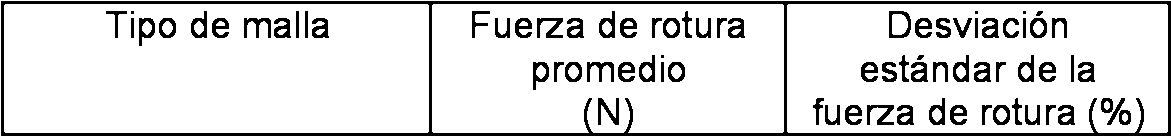
_______ _______ _______ _______

La tabla 3 confirma que, en promedio, el material de ultramalla Atiene una resistencia a la tracción o al rasgado en los puntos de intersección de los filamentos de urdimbre y de trama, tal como se mide mediante la fuerza de rotura del material, de más de 10 N, más de 15 N, e incluso más de 20 N. La resistencia al rasgado resultante es de bastante más del doble de la que presentan los materiales CLAF® sometidos a ensayo, a pesar del hecho de que el material de ultramalla A es más ligero y más abierto que los materiales CLAF®. Se cree que se obtendrían resultados comparables con los demás materiales de ultramalla descritos en el presente documento.Table 3 confirms that, on average, the ultramall material has a tensile or tearing strength at the points of intersection of the warp and weft filaments, as measured by the breaking force of the material, over of 10 N, more than 15 N, and even more than 20 N. The resulting tear strength is considerably more than double that of the CLAF® materials tested, despite the fact that the ultramamel A material It is lighter and more open than CLAF® materials. It is believed that comparable results would be obtained with the other ultramalla materials described herein.
Los materiales de ultramalla específicos descritos anteriormente, incluyendo el material 1, el material 2 y la ultramalla A, así como muchos otros materiales textiles y otras materiales de malla abierta que se encuentran dentro del alcance de la presente divulgación, podrían convertirse en cualquiera de una amplia variedad de artículos, tales como bolsas, vallas de sedimentos, cubiertas para balas o pantallas, mediante cualquiera de diversas operaciones de conversión. Podría realizarse esta conversión formando costuras a través de la aplicación de calor, mediante plegado, mediante cosido, a través del uso de adhesivos, o cualquier combinación de los mismos. Se describirán ahora tres de tales aplicaciones.The specific ultramalla materials described above, including material 1, material 2 and ultramall A, as well as many other textile materials and other open mesh materials that are within the scope of the present disclosure, could become any of a Wide variety of items, such as bags, sediment fences, bale covers or screens, by any of several conversion operations. This conversion could be done by forming seams through the application of heat, by folding, by sewing, through the use of adhesives, or any combination thereof. Three such applications will now be described.
2. Bolsas con costura en L2. Bags with L stitching
Los materiales de malla abierta según la presente divulgación, y también denominados “materiales de ultramalla” por motivos de concisión, pueden convertirse en una denominada bolsa con costura en L plegando el material sobre sí mismo para proporcionar una costura de borde vertical y cosiendo el material textil en sus bordes laterales e inferior. La bolsa resultante tendrá una parte superior abierta, un borde formado a partir de un pliegue, y un segundo borde y una parte inferior formada a partir de costuras. Estas costuras se forman normalmente mediante cosido, pero podrían formarse de manera concebible mediante unión térmica, usando adhesivos, o mediante alguna combinación de cualquiera o todos de estas tres y posiblemente otras técnicas. Las capas de urdimbre en el material textil preferiblemente se extenderán horizontalmente a lo largo de la bolsa para maximizar la resistencia de costura lateral. Haciendo referencia ahora a la figura 8, una bolsa de costura en L 20 incluye un primer extremo 22 y un segundo extremo dispuesto de manera opuesta 24. La bolsa 20 incluye además una costura lateral 26 que se extiende entre los extremos primero y segundo 22, 24. La bolsa se forma a partir de un material de malla abierta, preferiblemente uno de los materiales textiles no tejidos descritos anteriormente o un material textil u otro material de malla abierta que tenga características similares.The open mesh materials according to the present disclosure, and also referred to as "ultramalla materials" for reasons of concision, can be converted into a so-called L-seam bag by folding the material on itself to provide a vertical edge seam and sewing the material textile on its side and bottom edges. The resulting bag will have an open top, an edge formed from a fold, and a second edge and a bottom formed from seams. These seams are normally formed by stitching, but could conceivably be formed by thermal bonding, using adhesives, or by some combination of any or all of these three and possibly other techniques. The warp layers in the textile material will preferably be spread horizontally along the bag to maximize the side seam strength. Referring now to Figure 8, an L-shaped seam bag 20 includes a first end 22 and a second end oppositely disposed 24. The bag 20 further includes a side seam 26 extending between the first and second ends 22, 24. The bag is formed from an open mesh material, preferably one of the nonwoven fabrics described above or a textile material or other open mesh material having similar characteristics.
En la orientación representada de la figura 8, el primer extremo 22 de la bolsa 20 es un extremo inferior mientras que el segundo extremo 24 de la bolsa 20 es un extremo superior. El extremo inferior 22 es un extremo cerrado mientras que el extremo superior 24 es un extremo abierto. Sin embargo, el extremo superior podría cerrarse después de llenarse usando cualquier técnica adecuada.In the orientation shown in Figure 8, the first end 22 of the bag 20 is a lower end while the second end 24 of the bag 20 is an upper end. The lower end 22 is a closed end while the upper end 24 is an open end. However, the upper end could be closed after filling using any suitable technique.
En la realización representada, la bolsa 20 se forma mediante plegado (es decir, doblando sobre sí mismo) el material y cosiendo el material en sus bordes laterales e inferior de modo que la bolsa 20 incluya una cavidad interior 28. Las bolsas que tienen costuras laterales e inferior cosidas se denominan habitualmente bolsas cosidas en L. La costura lateral 26 de la bolsa 20 de esta realización se forma dando puntadas o cosiendo entre sí los lados opuestos del material después de haberse plegado el material. Un lado 30 que es opuesto a la costura lateral 26 es un pliegue o una doblez, que se forma doblando el material sobre sí mismo. El extremo inferior 22 incluye una costura 32 que se forma mediante cosido de una primera porción de un borde del material a una porción solapante del borde después de haberse plegado el material.In the embodiment shown, the bag 20 is formed by folding (i.e., bending over itself) the material and sewing the material at its side and bottom edges so that the bag 20 includes an interior cavity 28. The bags having seams The stitched side and bottom seams are commonly referred to as L-sewn bags. The side seam 26 of the bag 20 of this embodiment is formed by stitching or sewing together opposite sides of the material after the material has been folded. A side 30 which is opposite to the side seam 26 is a fold or a fold, which is formed by bending the material on itself. The lower end 22 includes a seam 32 which is formed by stitching a first portion of an edge of the material to an overlapping portion of the edge after the material has been folded.
En la realización representada, el material de la bolsa 20 es un material textil no tejido orientado de modo que los filamentos de urdimbre 15, 16 (figuras 1-3) son generalmente paralelos a la costura 32 del extremo inferior 22 de la bolsa 20. En la orientación representada, los filamentos de urdimbre 15, 16 se extienden horizontalmente a lo largo de la bolsa 20 para maximizar la resistencia de la costura lateral 26.In the embodiment shown, the material of the bag 20 is a nonwoven fabric oriented so that the warp filaments 15, 16 (Figures 1-3) are generally parallel to the seam 32 of the lower end 22 of the bag 20. In the orientation shown, the warp filaments 15, 16 extend horizontally along the bag 20 to maximize the strength of the side seam 26.
Haciendo referencia ahora a las figuras 8 y 9, se describirá el extremo superior 24 de la bolsa 20. El extremo superior 24 incluye un borde 34. El borde 34 define una abertura 36 que proporciona acceso a la cavidad interior 28. El extremo superior 24 incluye además una porción texturizada 38 dispuesta adyacente al borde 34. La porción texturizada 38 está adaptada para proporcionar una textura que es distinta de la textura del material textil de la bolsa 20. Esta textura distintiva de la porción texturizada 38 de la bolsa 20 permite a los usuarios identificar el extremo superior 24 de la bolsa 20 al tacto o la palpación.Referring now to Figures 8 and 9, the upper end 24 of the bag 20 will be described. The upper end 24 includes an edge 34. The edge 34 defines an opening 36 that provides access to the interior cavity 28. The upper end 24 further includes a textured portion 38 disposed adjacent the edge 34. The textured portion 38 is adapted to provide a texture that is distinct from the texture of the textile material of the bag 20. This distinctive texture of the textured portion 38 of the bag 20 allows Users identify the upper end 24 of the bag 20 by touch or palpation.
La porción texturizada 38 incluye un filamento 40. En una realización, el filamento 40 tiene un diámetro exterior que está en un intervalo de aproximadamente 0,1 mm a aproximadamente 1 mm. En otra realización, el diámetro exterior del filamento 40 está en un intervalo de aproximadamente 0,1 mm a aproximadamente 0,5 mm. En otra realización, el diámetro exterior del filamento 40 está en un intervalo de aproximadamente 0,2 mm a aproximadamente 0,3 mm. The textured portion 38 includes a filament 40. In one embodiment, the filament 40 has an outer diameter that is in a range of about 0.1 mm to about 1 mm. In another embodiment, the outer diameter of the filament 40 is in a range of about 0.1 mm to about 0.5 mm. In another embodiment, the outer diameter of the filament 40 is in a range of about 0.2 mm to about 0.3 mm.
En la realización representada de las figuras 8 y 9, la porción texturizada 38 incluye una pluralidad de filamentos 40. El filamento 40 se dispone sobre una superficie exterior del material textil de la bolsa 20 adyacente al borde 34 del extremo superior 24. En la realización representada, el filamento 40 se dispone sobre la superficie exterior del material textil de la bolsa 20 de modo que el filamento 40 no se entrelaza ni entrecruza con el material textil. El filamento 40 se extiende de manera continua alrededor del extremo superior 34 de la bolsa 20.In the embodiment shown in Figures 8 and 9, the textured portion 38 includes a plurality of filaments 40. The filament 40 is disposed on an outer surface of the textile material of the bag 20 adjacent the edge 34 of the upper end 24. In the embodiment shown, the filament 40 is disposed on the outer surface of the textile material of the bag 20 so that the filament 40 does not intertwine or interlock with the textile material. The filament 40 extends continuously around the upper end 34 of the bag 20.
En la realización representada de las figuras 8 y 9, el filamento 40 se orienta de modo que es generalmente paralelo a los filamentos de urdimbre 15, 16 del material textil de la bolsa 20. En otra realización, el filamento 40 es generalmente horizontal en la bolsa 20. En otra realización, el filamento 40 es generalmente paralelo a un plano en el que se dispone la abertura 36 del extremo superior 24.In the embodiment shown in Figures 8 and 9, the filament 40 is oriented so that it is generally parallel to the warp filaments 15, 16 of the textile material of the bag 20. In another embodiment, the filament 40 is generally horizontal in the bag 20. In another embodiment, the filament 40 is generally parallel to a plane in which the opening 36 of the upper end 24 is disposed.
En una realización, el filamento 40 es un monofilamento que se fabrica a partir de un material de polietileno de alta densidad (HDPE). En otra realización, el filamento 40 es un filamento coextruido que tiene una porción de portador y una porción de unión. La porción de portador puede fabricarse a partir de materiales incluyendo un polietileno de alta densidad (HDPE) o un polietileno de media densidad (MDPE) mientras que la porción de unión puede fabricarse a partir de materiales incluyendo un polietileno de baja densidad (LDPE) o polietileno lineal de baja densidad (LLDPE). En una realización, la porción texturizada 38 incluye una banda 42 que se extiende alrededor del extremo superior 24 de la bolsa 20 en una ubicación que es adyacente al borde 34 del extremo superior 24. La banda 42 es una tira estrecha de material. La banda 42 puede fabricarse a partir de un material termoplástico incluyendo polipropileno, polietileno de baja densidad, poliéster recubierto, etc. En una realización, el material de la banda 42 tiene un grosor de aproximadamente 25 micrómetros. En una realización, el material termoplástico de la banda 42 es transparente o translúcido. En otra realización, el material termoplástico de la banda 42 es opaco.In one embodiment, the filament 40 is a monofilament that is manufactured from a high density polyethylene (HDPE) material. In another embodiment, the filament 40 is a coextruded filament having a carrier portion and a joining portion. The carrier portion can be manufactured from materials including a high density polyethylene (HDPE) or a medium density polyethylene (MDPE) while the joining portion can be manufactured from materials including a low density polyethylene (LDPE) or linear low density polyethylene (LLDPE). In one embodiment, the textured portion 38 includes a band 42 that extends around the upper end 24 of the bag 20 at a location that is adjacent the edge 34 of the upper end 24. The band 42 is a narrow strip of material. The web 42 can be manufactured from a thermoplastic material including polypropylene, low density polyethylene, coated polyester, etc. In one embodiment, the web material 42 has a thickness of about 25 microns. In one embodiment, the thermoplastic material of the web 42 is transparent or translucent. In another embodiment, the thermoplastic material of the web 42 is opaque.
La banda 42 define una anchura W. En una realización, la anchura de la banda 42 es menor de o igual a aproximadamente 50,8 mm. En otra realización, la anchura W de la banda 42 es menor de o igual a aproximadamente 38,1 mm. En otra realización, la anchura W es menor de o igual a aproximadamente 25,4 mm. En otra realización, la banda 42 se usa sin el filamento 40. En esta realización, la superficie interior 46 de la banda 42 se une a las capas de urdimbre 14 y los filamentos de trama 11, 12.The web 42 defines a width W. In one embodiment, the width of the web 42 is less than or equal to about 50.8 mm. In another embodiment, the width W of the web 42 is less than or equal to about 38.1 mm. In another embodiment, the width W is less than or equal to about 25.4 mm. In another embodiment, the band 42 is used without the filament 40. In this embodiment, the inner surface 46 of the band 42 is joined to the warp layers 14 and the weft filaments 11, 12.
La banda 42 incluye una superficie exterior 44 y una superficie interior dispuesta de manera opuesta 46. En la realización representada de las figuras 8 y 9, la superficie interior 46 se une a las capas de urdimbre 14, los filamentos de trama 11, 12, y el filamento 40. En una realización, la superficie interior 46 de la banda 42 incluye una porción de unión que está adaptada para adherirse a las capas de urdimbre 14, los filamentos de trama 11, 12 y el filamento 40 a través de la aplicación de calor y presión.The band 42 includes an outer surface 44 and an opposed inner surface 46. In the embodiment shown in Figs. 8 and 9, the inner surface 46 is joined to the warp layers 14, the weft filaments 11, 12, and the filament 40. In one embodiment, the inner surface 46 of the band 42 includes a joining portion that is adapted to adhere to the warp layers 14, the weft filaments 11, 12 and the filament 40 through the application of heat and pressure.
Haciendo referencia ahora a la figura 10, se muestra una realización alternativa de una porción texturizada 138 de la bolsa 20. La porción texturizada 138 incluye la banda 42 y un filamento 140, que se dispone adyacente al borde 34 del extremo superior 24 de la bolsa 20. En la realización objeto, el filamento 140 se dispone sobre una superficie exterior de uno de los filamentos de urdimbre 16 de la capa de urdimbre 14 de modo que una porción del filamento 140 se dispone entre el filamento de urdimbre 16 y la banda 42.Referring now to Figure 10, an alternative embodiment of a textured portion 138 of the bag 20 is shown. The textured portion 138 includes the band 42 and a filament 140, which is disposed adjacent the edge 34 of the upper end 24 of the bag. 20. In the subject embodiment, the filament 140 is disposed on an outer surface of one of the warp filaments 16 of the warp layer 14 so that a portion of the filament 140 is disposed between the warp filament 16 and the web 42. .
El filamento 140 se dispone en un patrón de forma de onda no lineal (por ejemplo, cuadrado, triángulo, diente de sierra, seno, etc.). El patrón de forma de onda del filamento 140 es un patrón generalmente oscilante. El patrón oscilante del filamento 140 define una pluralidad de picos 148a y una pluralidad de valles 148b. En la realización representada, el patrón oscilante es generalmente sinusoidal.The filament 140 is arranged in a non-linear waveform pattern (e.g., square, triangle, sawtooth, sine, etc.). The waveform pattern of the filament 140 is a generally oscillating pattern. The oscillating pattern of the filament 140 defines a plurality of peaks 148a and a plurality of valleys 148b. In the embodiment shown, the oscillating pattern is generally sinusoidal.
Haciendo referencia ahora a la figura 11, se muestra una realización alternativa de una porción texturizada 238 de la bolsa 20. La porción texturizada 238 de la bolsa 20 incluye una pluralidad de filamentos 240. La pluralidad de filamentos incluye un primer filamento 240a y un segundo filamento 240b. El primer filamento 240a se dispone en un primer patrón de forma de onda no lineal mientras que el segundo filamento 240b se dispone en un segundo patrón de forma de onda no lineal. En la realización representada, los patrones de forma de onda primero y segundo son generalmente sinusoidales. El segundo patrón de forma de onda está desviado con respecto al primer patrón de forma de onda. Por ejemplo, en la realización representada, los patrones de forma de onda primero y segundo están desfasados 180°.Referring now to Figure 11, an alternative embodiment of a textured portion 238 of the bag 20 is shown. The textured portion 238 of the bag 20 includes a plurality of filaments 240. The plurality of filaments includes a first filament 240a and a second filament 240a. filament 240b. The first filament 240a is disposed in a first non-linear waveform pattern while the second filament 240b is disposed in a second non-linear waveform pattern. In the embodiment shown, the first and second waveform patterns are generally sinusoidal. The second waveform pattern is deviated from the first waveform pattern. For example, in the embodiment shown, the first and second waveform patterns are 180 ° out of phase.
Haciendo referencia de nuevo a la figura 8, la bolsa 20 incluye una etiqueta 50. La etiqueta 50 se extiende alrededor de al menos una porción de la bolsa 20. En la realización representada, la etiqueta 50 se dispone entre los extremos inferior y superior 22, 24 de la bolsa 20.Referring again to FIG. 8, the bag 20 includes a label 50. The label 50 extends around at least a portion of the bag 20. In the embodiment shown, the label 50 is disposed between the lower and upper ends. , 24 of the bag 20.
La etiqueta 50 incluye una superficie exterior 52 y una superficie interior dispuesta de manera opuesta. La superficie exterior 52 está adaptada para incluir marcas (por ejemplo, colores, números, letras, símbolos, etc.) referentes a información (por ejemplo, fabricante, peso, ingredientes, fechas, información nutricional, etc.) sobre el contenido dispuesto en la cavidad interior 28 de la bolsa 20.The label 50 includes an outer surface 52 and an inner surface arranged in an opposite manner. The outer surface 52 is adapted to include marks (e.g., colors, numbers, letters, symbols, etc.) relating to information (e.g., manufacturer, weight, ingredients, dates, nutritional information, etc.) on the content provided in the inner cavity 28 of the bag 20.
La superficie interior de la etiqueta 50 puede ser una superficie libre de adhesivo. Se entenderá que el término “libre de adhesivo” significa que la superficie interior no incluye un adhesivo aplicado o un recubrimiento adhesivo. La superficie interior de la etiqueta 50 se fija a los filamentos compuestos del material textil de la bolsa 20 a través de la aplicación de calor y presión. En una realización, la superficie interior de la etiqueta 50 se fija a las capas de urdimbre 14 de la bolsa 20. En otra realización, la superficie interior de la etiqueta 50 se fija a las capas de urdimbre y de trama de la bolsa 20.The interior surface of the label 50 can be a surface free of adhesive. It will be understood that the term "adhesive-free" means that the interior surface does not include an applied adhesive or an adhesive coating. The The interior surface of the label 50 is fixed to the filaments composed of the textile material of the bag 20 through the application of heat and pressure. In one embodiment, the inner surface of the label 50 is attached to the warp layers 14 of the bag 20. In another embodiment, the inner surface of the label 50 is attached to the warp and weft layers of the bag 20.
Haciendo referencia ahora a la figura 12, se muestra una realización alternativa de una bolsa 320, que se construye a partir de un material de malla abierta de la presente divulgación. La bolsa 320 incluye un extremo inferior 322, un extremo superior dispuesto de manera opuesta 324 y una costura lateral 326 que se extiende entre los extremos inferior y superior 322, 324.Referring now to Figure 12, there is shown an alternative embodiment of a bag 320, which is constructed from an open mesh material of the present disclosure. The bag 320 includes a lower end 322, an opposite end end 324 and a side seam 326 extending between the lower and upper ends 322, 324.
El extremo inferior 322 es un extremo cerrado mientras que el extremo superior 324 está abierto. El extremo superior 324 define una abertura 336 que proporciona acceso a una cavidad interior 328 de la bolsa 320.The lower end 322 is a closed end while the upper end 324 is open. The upper end 324 defines an opening 336 that provides access to an interior cavity 328 of the bag 320.
La bolsa 320 de esta realización incluye además un elemento de cierre 360. El elemento de cierre 360 está adaptado para cerrar selectivamente la abertura 336 para impedir o bloquear el acceso a la cavidad interior 328 de la bolsa 320. En una realización, el elemento de cierre 360 es un material textil tricotado de urdimbre. En otra realización, el elemento de cierre 360 es un material textil no tejido. El elemento de cierre 360 puede fabricarse a partir de un material termoplástico tal como polietileno, polipropileno, polietileno de alta densidad, nailon, poliésteres, etc.The bag 320 of this embodiment further includes a closure element 360. The closure member 360 is adapted to selectively close the opening 336 to prevent or block access to the interior cavity 328 of the bag 320. In an embodiment, the security element 360 closure is a warp knitted textile material. In another embodiment, the closure element 360 is a nonwoven fabric. The closure element 360 can be manufactured from a thermoplastic material such as polyethylene, polypropylene, high density polyethylene, nylon, polyesters, etc.
El elemento de cierre 360 se dispone en el extremo superior 324 de la bolsa 320. El elemento de cierre 360 se dispone libremente entre los filamentos de trama 11, 12 de modo que los filamentos de trama 11, 12 pueden deslizar a lo largo del elemento de cierre 360. En la realización representada, el elemento de cierre 360 se dispone entre los filamentos de trama 11, 12 de modo que el elemento de cierre 360 es generalmente paralelo a los filamentos de urdimbre 16 de la bolsa 320. Mientras que el elemento de cierre 360 se captura entre los filamentos de trama 11, 12, el elemento de cierre 360 se fija a la bolsa 320 en la costura lateral 326.The closing element 360 is disposed at the upper end 324 of the bag 320. The closing element 360 is freely disposed between the weft filaments 11, 12 so that the weft filaments 11, 12 can slide along the element 360. In the embodiment shown, the closure element 360 is disposed between the weft filaments 11, 12 so that the closure element 360 is generally parallel to the warp filaments 16 of the bag 320. While the element of closure 360 is captured between the weft filaments 11, 12, the closure element 360 is fixed to the bag 320 in the side seam 326.
Para cerrar la abertura 336 del extremo superior 324, se tira del elemento de cierre 360 en una dirección que es generalmente hacia fuera desde el extremo superior 324. A medida que se tira del elemento de cierre 360, los filamentos de trama 11, 12 se deslizan a lo largo del elemento de cierre 360 hacia otros filamentos de trama 11, 12 del material textil de la bolsa 320 y se agrupan entre sí. A medida que los filamentos de trama 11, 12 se deslizan a lo largo del elemento de cierre 360, se reduce el tamaño de la abertura 336. Cuando los filamentos de trama 11, 12 se agrupan entre sí, el elemento de cierre 360 puede amarrarse para fijar el extremo superior 324 en una posición cerrada (es decir, cuando la abertura 336 se cierra).To close the opening 336 of the upper end 324, the closure element 360 is pulled in a direction that is generally outwardly from the upper end 324. As the closure element 360 is pulled, the weft filaments 11, 12 they slide along the closing element 360 towards other weft filaments 11, 12 of the textile material of the bag 320 and are grouped together. As the weft filaments 11, 12 slide along the closing element 360, the size of the opening 336 is reduced. When the weft filaments 11, 12 are grouped together, the closure element 360 can be tied together for fixing the upper end 324 in a closed position (ie, when the opening 336 closes).
Haciendo referencia ahora a la figura 13, se muestra una realización alternativa de una bolsa 520, que se construye a partir del material textil de la presente divulgación. La bolsa 520 incluye un extremo inferior 522, un extremo superior dispuesto de manera opuesta 524 y una costura lateral 526 que se extiende entre los extremos inferior y superior 522, 524.Referring now to Figure 13, there is shown an alternative embodiment of a pouch 520, which is constructed from the textile material of the present disclosure. The bag 520 includes a lower end 522, an upper end arranged in opposite manner 524, and a side seam 526 extending between the lower and upper ends 522, 524.
El extremo inferior 522 es un extremo cerrado mientras que el extremo superior 524 es un extremo abierto. El extremo inferior 522 incluye una costura 532 que se forma mediante cosido de una primera porción de un borde del material textil a una porción solapante del borde después de haberse plegado el material textil. El extremo superior 524 define una abertura 536 que proporciona acceso a una cavidad interior 528 de la bolsa 520.The lower end 522 is a closed end while the upper end 524 is an open end. The lower end 522 includes a seam 532 which is formed by stitching a first portion of an edge of the fabric to an overlapping portion of the edge after the fabric has been folded. The upper end 524 defines an opening 536 that provides access to an inner cavity 528 of the bag 520.
La bolsa 520 incluye una pluralidad de cordones 570. La pluralidad de cordones 570 están adaptados para aumentar la resistencia de enganche de la bolsa 520 sin aumentar significativamente el peso de la bolsa 520.The pouch 520 includes a plurality of cords 570. The plurality of cords 570 are adapted to increase the engagement resistance of the pouch 520 without significantly increasing the weight of the pouch 520.
La pluralidad de cordones 570 se dispone en la bolsa 520 de modo que los cordones 570 son generalmente paralelos a los filamentos de urdimbre 16 del material textil. En una realización, los cordones 570 se disponen adyacentes a los filamentos de urdimbre 16. En otra realización, los cordones 570 se disponen entre filamentos de urdimbre adyacentes 16. En otra realización, los cordones 570 se disponen sobre los filamentos de urdimbre 16. En una realización, cada uno de los cordones 570 tiene una porción de extremo 572 que se fija en la costura lateral 526 de la bolsa 520.The plurality of strands 570 are disposed in the bag 520 so that the strands 570 are generally parallel to the warp filaments 16 of the textile material. In one embodiment, the cords 570 are disposed adjacent the warp filaments 16. In another embodiment, the cords 570 are disposed between adjacent warp filaments 16. In another embodiment, the cords 570 are disposed over the warp filaments 16. In an embodiment, each of the cords 570 has an end portion 572 that is fixed to the side seam 526 of the bag 520.
Los cordones 570 tienen una resistencia a la tracción que es mayor que o igual a la resistencia a la tracción de los filamentos de urdimbre 16. Los cordones 570 pueden fabricarse a partir de diversos materiales. En una realización, cada uno de los cordones 570 es un material no tejido o termoplástico tal como un material de poliéster. En otra realización, cada uno de los cordones 570 puede producirse a partir de la hebra usada para fijar la costura lateral 526 y la costura 532 en el extremo inferior 522.The cords 570 have a tensile strength that is greater than or equal to the tensile strength of the warp filaments 16. The cords 570 may be fabricated from various materials. In one embodiment, each of the cords 570 is a nonwoven or thermoplastic material such as a polyester material. In another embodiment, each of the cords 570 can be produced from the thread used to secure the side seam 526 and the seam 532 at the lower end 522.
Los cordones 570 se disponen a intervalos a lo largo de una distancia axial D de la bolsa 520. En una realización, los intervalos entre los cordones 570 se fijan (es decir, los intervalos entre los cordones 570 son iguales). En otra realización, los intervalos entre los cordones 570 varían de modo que los intervalos entre cordones son desiguales. En una realización, la distancia axial D a la que se disponen los cordones 570 es igual a una longitud L (es decir, desde el extremo inferior 522 hasta el extremo superior 524) de la bolsa 520. En otra realización, los cordones 570 pueden localizarse a lo largo de la longitud L dependiendo de la aplicación particular para la bolsa 520 de modo que la distancia axial D es menor que la longitud L de la bolsa 520. En una realización, los cordones 570 se disponen en la mitad inferior de la bolsa 520 de modo que la distancia axial D es menor que o igual a 0,5L tal como se mide desde el extremo inferior 522 de la bolsa 520. En otra realización, los cordones 570 se disponen en un tercio inferior de la bolsa 520 de modo que la distancia axial D es menor de o igual a 0,33L tal como se mide desde el extremo inferior 522 de la bolsa 520. En otra realización, los cordones 570 se disponen en el cuarto inferior de la bolsa 520 de modo que la distancia axial D es menor que o igual a 0,25L tal como se mide desde el extremo inferior 522 de la bolsa 520.The cords 570 are arranged at intervals along an axial distance D of the bag 520. In one embodiment, the intervals between the cords 570 are fixed (i.e., the intervals between the cords 570 are equal). In another embodiment, the intervals between the cords 570 vary so that the intervals between cords are unequal. In one embodiment, the axial distance D to which the cords 570 are disposed is equal to a length L (i.e., from the lower end 522 to the upper end 524) of the bag 520. In another embodiment, the cords 570 can located along the length L depending on the particular application for the bag 520 so that the axial distance D is smaller than the length L of the bag 520. In one embodiment, the cords 570 are arranged in the lower half of the bag 520 so that the axial distance D is less than or equal to 0.5L such as it is measured from the lower end 522 of the bag 520. In another embodiment, the cords 570 are disposed in a lower third of the bag 520 so that the axial distance D is less than or equal to 0.33L as measured from the lower end 522 of the bag 520. In another embodiment, the cords 570 are arranged in the lower quarter of the bag 520 so that the axial distance D is less than or equal to 0.25L as measured from the lower end 522 of the bag 520.
Haciendo referencia ahora a las figuras 14 y 15, se muestra una realización alternativa de los cordones 570 para la bolsa 520. En esta realización alternativa, el cordón 570 se dispone sobre el filamento de urdimbre 16 de modo que el cordón 570 forma un patrón de forma de onda (por ejemplo, cuadrada, triangular, en diente de sierra, sinusoidal, etc.). En la realización representada de la figura 14, el patrón de forma de onda tiene una forma generalmente sinusoidal.Referring now to Figures 14 and 15, an alternate embodiment of the cords 570 for the pouch 520 is shown. In this alternative embodiment, the cord 570 is disposed over the warp filament 16 so that the cord 570 forms a pattern waveform (for example, square, triangular, sawtooth, sinusoidal, etc.). In the embodiment shown in Figure 14, the waveform pattern has a generally sinusoidal shape.
En la realización representada de la figura 15, una pluralidad de cordones 570 se disponen sobre cada filamento de urdimbre 16. La pluralidad de cordones 570 incluye un primer cordón 570a y un segundo cordón 570b. El primer cordón 570a se dispone en un primer patrón de forma de onda mientras que el segundo cordón 570b se dispone en un segundo patrón de forma de onda. En la realización representada, los patrones de forma de onda primero y segundo son generalmente sinusoidales. El segundo patrón de forma de onda está desviado con respecto al primer patrón de forma de onda. Por ejemplo, en la realización representada, los patrones de forma de onda primero y segundo están desfasados 180°.In the embodiment shown in Figure 15, a plurality of strands 570 are disposed on each warp filament 16. The plurality of strands 570 includes a first strand 570a and a second strand 570b. The first bead 570a is arranged in a first waveform pattern while the second bead 570b is arranged in a second waveform pattern. In the embodiment shown, the first and second waveform patterns are generally sinusoidal. The second waveform pattern is deviated from the first waveform pattern. For example, in the embodiment shown, the first and second waveform patterns are 180 ° out of phase.
Al formarse a partir de un material de ultramalla, la bolsa de costura en L construida según la presente divulgación, denominada en el presente documento bolsa con costura en L de “nuevo tipo” por motivos de concisión, presenta una apilabilidad superior en comparación con bolsas cosidas en L de la técnica anterior. Tradicionalmente, las bolsas cosidas en L se han enviado y almacenado en “balas” en las que se comprimen varios miles de bolsas y se unen entre sí usando una envuelta entrelazada y/o retráctil. Cada bala contiene normalmente cuatro o cinco apilamientos de bolsas de números iguales dispuestas unas junto a otras. Las balas unidas se apilan entonces en un palé y se comprimen hasta una altura final, normalmente de aproximadamente 50 pulgadas (127 cm), y se envuelve todo el palé con envoltura retráctil. Entonces se colocan varios palés en un camión para su envío.When formed from an ultramalla material, the L-shaped seam bag constructed in accordance with the present disclosure, referred to herein as a "new type" L-seam bag for reasons of concision, exhibits superior stackability as compared to bags. sewn in L of the prior art. Traditionally, L-sewn bags have been shipped and stored in "bales" in which several thousand bags are compressed and joined together using an interlaced and / or retractable wrap. Each bullet usually contains four or five stacks of equal number bags arranged next to each other. The bales attached are then stacked on a pallet and compressed to a final height, typically about 50 inches (127 cm), and the entire pallet is wrapped with shrink wrap. Then several pallets are placed on a truck for shipment.
Se sometió a ensayo la apilabilidad de bolsas con costura en L de nuevo tipo, producidas a partir del material de ultramalla A descrito anteriormente, frente a bolsas cosidas en L de tricotado Raschel tradicionales usando este procedimiento de embalado y paletizado. Se sometieron a ensayo dos tamaños de cada tipo de bolsa: una bolsa de 10 lb y una bolsa de 5 lb. Debe indicarse en este momento que los tamaños de bolsa se denominan a menudo en la industria del envasado en función de su capacidad basada en el peso o volumétrica pretendida. Así, una bolsa de 10 lb es una que está diseñada para tener una capacidad de trabajo de 10 lbs (4,5 kg), una bolsa de 5 lb es una que está diseñada para tener una capacidad de trabajo de 5 lbs (2,7 kg), etc.The stackability of new type L seam bags, produced from the ultramamel A material described above, was tested against traditional Raschel knit-seam L-bags using this packaging and palletizing method. Two sizes of each type of bag were tested: a 10 lb. bag and a 5 lb. bag. It should be noted at this time that bag sizes are often referred to in the packaging industry based on their capacity based on the intended weight or volume. Thus, a 10 lb bag is one that is designed to have a working capacity of 10 lbs (4.5 kg), a 5 lb bag is one that is designed to have a working capacity of 5 lbs (2, 7 kg), etc.
Las bolsas se embalaron usando una fuerza de 60.000 lbs (267 kN) y se apilaron sobre palés usando la técnica descrita anteriormente. Se resumen los resultados de ensayo de los ensayos en la tabla 4 a continuación:The bags were packed using a force of 60,000 lbs (267 kN) and stacked on pallets using the technique described above. The test results of the tests are summarized in Table 4 below:
TABLA 4: APILABILIDAD DE BOLSAS CON COSTURA EN LTABLE 4: STACKING OF BAGS WITH SEWING

Las mejoras son significativas.The improvements are significant.
Tal como puede observarse a partir de la tabla 4 anterior, se comprimieron 3.000 bolsas con costura en L de tricotado Raschel de 10 lb hasta una altura de 14 pulgadas (35,6 cm) durante el procedimiento de embalado, dando como resultado la formación de un apilamiento de 43,7 bolsas/cm cuando se sometieron las bolsas apiladas a una fuerza de 267 kN. Así, cada bala contenía 3.000 bolsas. Comparativamente, se comprimieron 4.000 bolsas con costura en L de ultramalla de 10 lb de nuevo tipo hasta una altura de 9 pulgadas (22,3 cm) durante el procedimiento de embalado, dando como resultado la formación de un apilamiento de 21,1 bolsas/cm cuando se sometieron las bolsas apiladas a una fuerza de 267 kN. Estos ensayos confirman por tanto que someter apilamientos de bolsas con costura en L construidas según la presente divulgación a una fuerza de 267 kN forma un apilamiento que tiene más de 25 bolsas/cm, más de 30 bolsas/cm, e incluso más de 35 bolsas/cm. As can be seen from Table 4 above, 3,000 Raschel knitted L-seam bags of 10 lbs. Were compressed to a height of 14 inches (35.6 cm) during the wrapping process, resulting in the formation of a stack of 43.7 bags / cm when the piled bags were subjected to a force of 267 kN. Thus, each bullet contained 3,000 bags. Comparatively, 4,000 bags of 10-lb. Ultramall L-seam of new type were compressed to a height of 9 inches (22.3 cm) during the packaging process, resulting in the formation of a stack of 21.1 bags / cm when the piled bags were subjected to a force of 267 kN. These tests therefore confirm that subjecting stacks of L-shaped bags constructed according to the present disclosure to a force of 267 kN forms a stack having more than 25 bags / cm, more than 30 bags / cm, and even more than 35 bags / cm.
Debido a la altura reducida de la bala de las bolsas de malla de nuevo tipo en comparación con una bala de bolsas cosidas en L de tricotado Raschel, fue posible almacenar más balas sobre un palé. Con fines de envío y almacenamiento, se considera que la altura máxima deseada de un palé y los artículos almacenados sobre el mismo es normalmente de aproximadamente 50 pulgadas (127 cm). Las balas de bolsas cosidas en L de tricotado Raschel de 10 lb se apilan normalmente sobre un palé en cuatro capas, conteniendo cada uno dos balas. Debido a la altura de bala reducida de las bolsas con costura en L de 10 lb de nuevo tipo producidas a partir del material de ultramalla A, pueden apilarse dos filas adicionales de balas sobre un palé hasta esencialmente la misma altura final. Por tanto, el mismo palé puede contener 12 balas de bolsas con costura en L de 10 lb de nuevo tipo en contraposición a solamente 8 balas de bolsas cosidas en L de 10 lb de tricotado Raschel tradicionales. Como resultado, pueden almacenarse 48.000 bolsas de 10 lb de nuevo tipo sobre un palé, en comparación con solamente 24.000 bolsas cosidas en L de 10 lb de tricotado Raschel de la técnica anterior. Puede enviarse y almacenarse un cincuenta por ciento más de bolsas en un volumen dado. Los requisitos de espacio de envío y almacenamiento se reducen de manera espectacular, reduciendo adicionalmente la huella de carbono de las bolsas. La tabla 4 confirma que se obtienen mejoras similares para las bolsas cosidas en L de 5 lb de ultramalla.Due to the reduced bullet height of the new type mesh bags compared to a bullet of Raschel knitted L-shaped bags, it was possible to store more bullets on a pallet. For shipping and storage purposes, it is considered that the maximum desired height of a pallet and the items stored thereon is normally approximately 50 inches (127 cm). 10-liter Raschel-knit L-shaped bag bales are usually stacked on a four-layer pallet, each containing two bullets. Due to the reduced bullet height of the 10 lb. L-shaped seams of new type produced from the ultramall material A, two additional rows of bales can be stacked on a pallet to essentially the same final height. Therefore, the same pallet can contain 12 bullets of L-shaped bags of 10 lb of new type as opposed to only 8 bullets of 10-liter L-seams of traditional Raschel knitting. As a result, 48,000 10-lb bags of new type can be stored on one pallet, compared to only 24,000 10-liter L-sewn bags of prior-art Raschel knitting. Fifty percent more bags can be sent and stored in a given volume. The space and shipping space requirements are dramatically reduced, further reducing the carbon footprint of the bags. Table 4 confirms that similar improvements are obtained for the 5 lb. ultramall L-seam bags.
3. Bolsas de formación, llenado y sellado3. Training bags, filling and sealing
Los materiales de ultramalla descritos en el presente documento, u otros materiales que tienen al menos algunas de las características de los materiales de ultramalla, también pueden usarse para producir bolsas multisustrato que tienen porciones tanto de hoja como de malla abierta con al menos una costura unida térmicamente. Aunque ahora se describirán realizaciones de bolsas de formación, llenado y sellado (FFS) que adoptan la forma de bolsas de formación, llenado y sellado vertical (VFFS) de cuatro paneles, al menos muchos de los conceptos comentados en el presente documento también son aplicables a otras bolsas de formación, llenado y sellado vertical, bolsas de formación, llenado y sellado horizontal (HFFS), y cualquier otra bolsa FFS multisustrato que tiene al menos una malla de sellado de costura de extremo y porciones de película unidas térmicamente entre sí.The ultramamel materials described herein, or other materials having at least some of the characteristics of the ultramalla materials, can also be used to produce multi-substrate bags having both open sheet and mesh portions with at least one joined seam thermally Although embodiments of forming, filling and sealing bags (FFS) which take the form of four-panel vertical forming, filling and sealing bags (VFFS) will now be described, at least many of the concepts discussed in this document are also applicable to other training bags, vertical filling and sealing, forming bags, horizontal filling and sealing (HFFS), and any other multi-substrate FFS bag having at least one end seam sealing mesh and portions of film thermally bonded together.
Volviendo en primer lugar a las figuras 16-21 y a las figuras 16-18 en particular, una primera realización de una bolsa FFS 1.020 comprende una denominada bolsa VFFS de cuatro paneles que tiene lados frontal 1.022, trasero 1.024, izquierdo 1.026, y derecho 1.028 y extremos superior 1.030, e inferior 1.032. La bolsa se llena con artículos tales como productos agrícolas u otros productos alimenticios. El término “llena” tal como se usa en el presente documento no significa que todo el volumen interior de la bolsa deba estar ocupado por artículos. En efecto, en aplicaciones comerciales, una bolsa normalmente se “llena” hasta su peso nominal de artículos almacenados mientras que los artículos ocupan menos del 70%, y bastante a menudo menos del 50%, del volumen interior de la bolsa. Artículos que pueden almacenarse en estas bolsas pueden ser, por ejemplo, nueces, naranjas, patatas, cebollas, marisco (tal como gambas, mejillones o almejas), periódicos, bulbos de flores, judías secas o caramelos envueltos.Turning first to Figures 16-21 and Figures 16-18 in particular, a first embodiment of a FFS bag 1.020 comprises a so-called four-panel VFFS bag having front 1.022, rear 1.024, left 1.026, and right 1.028 sides. and upper ends 1,030, and lower 1,032. The bag is filled with items such as agricultural products or other food products. The term "filled" as used herein does not mean that the entire interior volume of the bag must be occupied by articles. Indeed, in commercial applications, a bag is normally "filled" up to its nominal weight of stored items while the articles occupy less than 70%, and quite often less than 50%, of the inner volume of the bag. Items that can be stored in these bags can be, for example, nuts, oranges, potatoes, onions, seafood (such as prawns, mussels or clams), newspapers, flower bulbs, dried beans or wrapped candies.
La bolsa 1.020 es generalmente cuadrada a lo largo de la mayor parte de su longitud cuando se llena con materiales, excepto cuando se pliega en los extremos superior e inferior 1.030 y 1.032 cuando se sellan entre sí los lados frontal y trasero opuestos 1.022 y 1.024 con los extremos de los lados izquierdo y derecho 1.026 y 1.028 intercalados entre los mismos. También podría ser rectangular o tener otra forma de la sección transversal poligonal y presentar muchas, si no todas, las características comentadas en el presente documento. Los lados izquierdo y derecho 1.026 y 1.028 se forman a partir de un material de malla abierta reforzado 1.100. Al menos un extremo de cada una de las superficies exteriores de los lados frontal y trasero 1.022 y 1.024 se forma al menos en parte a partir de un material de hoja 1.102 que se extiende a lo largo de la bolsa desde un extremo sellado de la bolsa. Ambos extremos de uno o ambos de los lados frontal y trasero pueden producirse a partir del material de hoja. En la realización ilustrada, el material de hoja se extiende por toda la longitud de los lados frontal y trasero. En la bolsa 1.020 de la realización ilustrada, el lado trasero 1.024 se forma en su totalidad a partir del material de hoja 1.102, y el lado frontal 1.022 de la bolsa 1.020 se forma a partir del material de malla abierta 1.100 revestido con el material de hoja 1.102.The bag 1,020 is generally square along most of its length when filled with materials, except when folded at the upper and lower ends 1,030 and 1,032 when the opposite front and rear sides are sealed together 1,022 and 1,024 with the ends of the left and right sides 1,026 and 1,028 interspersed between them. It could also be rectangular or have another shape of the polygonal cross section and present many, if not all, of the features discussed in this document. The left and right sides 1,026 and 1,028 are formed from a 1,100 reinforced open mesh material. At least one end of each of the outer surfaces of the front and rear sides 1022 and 1024 is formed at least in part from a sheet material 1,102 that extends along the bag from a sealed end of the bag . Both ends of one or both of the front and rear sides can be produced from the sheet material. In the illustrated embodiment, the sheet material extends over the entire length of the front and back sides. In the bag 1,020 of the illustrated embodiment, the rear side 1024 is formed entirely from the sheet material 1102, and the front side 1022 of the bag 1020 is formed from the open mesh material 1100 coated with the backing material. sheet 1.102.
Haciendo referencia a las figuras 20 y 21, el material de hoja 1.102 del lado frontal 1.022 de la bolsa 1.020 se extiende preferiblemente por toda la anchura del lado frontal 1.022, pero puede extenderse por menos de toda la anchura si se desea. Se termosella al material textil de malla 1.100 subyacente en sus bordes mediante costuras 1.034, 1.036 que son de aproximadamente % de pulgada (0,64 cm) a 3/8 de pulgada (0,95 cm) de ancho. El lado trasero 1.024 de la bolsa 1.020 tiene dos costuras que se extienden verticalmente 1.038, 1.040 en las esquinas del mismo en las que el material de película 1.102 se solapa con los bordes del material textil de malla abierta 1.100. Ambas costuras 1.038, 1.040 comprenden costuras de solapamiento. Se cierra al menos el extremo inferior 1.032, posiblemente mediante cosido o sujeción pero más preferiblemente mediante unión térmica. En la realización ilustrada, ambos extremos superior e inferior 1.030 y 1.032 de la bolsa 1.020 se cierran mediante costuras unidas térmicamente. Estas costuras pueden adoptar la forma de costuras de aleta o piel 1.042, 1.044 formadas presionando juntas dos barras de sellado, también tal como se comenta más adelante. Podrían formarse alternativamente mediante otras costuras tales como costuras de solapamiento. Las costuras superior e inferior 1.042, 1.044 tienen normalmente una longitud L de aproximadamente 3/8 de pulgada (0,95 cm) a A de pulgada (1,27 cm). La bolsa 1.020 ilustrada tiene una capacidad de almacenamiento de una a tres lbs y es aproximadamente de 4 pulgadas (10,2 cm) de ancho por 10 pulgadas (25,4 cm) de alto. Sin embargo, los conceptos comentados en el presente documento son igualmente aplicables a bolsas más grandes o más pequeñas de diferentes proporciones. Referring to Figures 20 and 21, the sheet material 1102 on the front side 1,022 of the bag 1,020 preferably extends over the entire width of the front side 1,022, but may extend for less than the entire width if desired. The underlying 1,100 mesh textile at its edges is heat sealed by 1,034, 1,036 seams that are approximately% inch (0.64 cm) to 3/8 inch (0.95 cm) wide. The back side 1,024 of the bag 1,020 has two vertically extending seams 1,038, 1,040 at the corners thereof in which the film material 1,102 overlaps the edges of the open mesh 1,100 textile material. Both 1.038, 1.040 seams comprise overlapping seams. At least the lower end 1,032 is closed, possibly by sewing or clamping but more preferably by thermal bonding. In the illustrated embodiment, both upper and lower ends 1,030 and 1,032 of the bag 1,020 are closed by thermally bonded seams. These seams may take the form of fin seams or skin 1,042, 1,044 formed by pressing together two sealing rods, also as discussed below. They could alternatively be formed by other seams such as overlapping seams. The upper and lower seams 1042, 1044 normally have a length L of about 3/8 inch (0.95 cm) to inch A (1.27 cm). The illustrated bag 1020 has a storage capacity of one to three lbs and is approximately 4 inches (10.2 cm) wide by 10 inches (25.4 cm) high. However, the concepts discussed in this document are equally applicable to larger or smaller bags of different proportions.
El material de hoja 1.102 puede ser cualquier material de hoja que pueda unirse con calor a sí mismo y a otros materiales. Puede recibir preferiblemente marcas en su capa exterior. Podría bastar un material producido en su totalidad o en parte a partir de un material de película de resina sintética. Un material de ese tipo es un denominado laminado de PET que tiene una capa delgada de un material de poliéster de punto de fusión relativamente alto, que sirve como superficie de impresión, laminado sobre una capa relativamente gruesa de un material de polietileno lineal de baja densidad (LLDPE) de punto de fusión relativamente bajo. El material de LLDPE se funde durante el procedimiento de unión con calor para sellar el material de película a materiales adyacentes. Un material preferido es aproximadamente de 3 mil (0,076 mm) de grosor. Sin embargo, tal como se comenta en más detalle más adelante, otras materiales de diferente grosores se han sometido a ensayo de manera satisfactoria. También podrían usarse otros materiales de hoja.The sheet material 1.102 can be any sheet material that can be heat bonded to itself and other materials. It can preferably receive marks on its outer layer. A material produced in whole or in part from a synthetic resin film material could suffice. Such a material is a so-called PET laminate having a thin layer of a polyester material of relatively high melting point, which serves as a printing surface, laminated on a relatively thick layer of a linear low density polyethylene material. (LLDPE) of relatively low melting point. The LLDPE material is melted during the heat bonding process to seal the film material to adjacent materials. A preferred material is approximately 3 mil (0.076 mm) thick. However, as discussed in more detail below, other materials of different thicknesses have been tested satisfactorily. Other sheet materials could also be used.
El material de malla abierta 1.100 es de un tipo de ultramalla y, por tanto, se forma a partir de varios filamentos que se intersecan, al menos algunos de los cuales son filamentos compuestos formados a partir de un material compuesto que tiene una porción de “portador” de alto punto de fusión y una porción de “unión” de punto de fusión relativamente bajo. Puede adoptar la forma de uno de los materiales textiles no tejidos descritos generalmente con anterioridad junto con las figuras 1-7.The open mesh material 1100 is of an ultramall type and, therefore, is formed from several intersecting filaments, at least some of which are composite filaments formed from a composite material having a portion of " carrier "of high melting point and a" union "portion of relatively low melting point. It may take the form of one of the non-woven fabrics generally described above together with Figures 1-7.
Pasando ahora a las figuras 22 y 23, las bolsas 1.020 pueden fabricarse en una máquina vertical de formación, llenado y sellado 1.050 que forma bolsas llenas de producto a partir de rollos 1.060 y 1.062 del material textil de malla abierta 1.100 y el material de hoja 1.102, respectivamente. La máquina 1.050 incluye un armazón 1.052, una estación de formación de sustrato 1.054, un dispensador de producto 1.056 y un conjunto de formación, llenado y sellado 1.058. La estación de formación de sustrato 1.054 forma una tira continua de un sustrato compuesto 1.200 a partir de rollos 1.060, 1.062 de malla y película. El conjunto de formación, llenado y sellado 1.058 recibe lotes de producto a partir del dispensador de producto 1.056 y forma simultáneamente bolsas 1.020 a partir del sustrato 1.200, llena esas bolsas 1.020 con el producto y sella los extremos de las bolsas formadas y llenas 1.020.Turning now to Figures 22 and 23, the bags 1,020 can be manufactured in a vertical forming, filling and sealing machine 1050 which forms product filled bags from rolls 1,060 and 1,062 of the 1,100 open mesh textile and the sheet material 1,102, respectively. The machine 1050 includes a frame 1,052, a substrate formation station 1,054, a product dispenser 1,056 and a forming, filling and sealing assembly 1,058. The substrate forming station 1054 forms a continuous strip of a composite substrate 1200 from rolls 1,060, 1,062 mesh and film. The 1.058 training, filling and sealing assembly receives batches of product from the 1056 product dispenser and simultaneously forms 1020 bags from the 1200 substrate, fills those 1020 bags with the product and seals the ends of the 1.020 formed and filled bags.
La estación de formación de sustrato 1.054 incluye rollos de extracción primero y segundo 1.060 y 1.062 para el material textil de malla abierta 1.100 y la película 1.102, respectivamente. El material textil de malla abierta 1.100 se bobina preferiblemente sobre el rollo en una tira continua 1.202 extendiéndose los filamentos de urdimbre a lo largo de la tira o en la dirección de la máquina. Los filamentos de urdimbre pueden extenderse en última instancia verticalmente en las bolsas acabadas. El segundo rollo de extracción 1.062 soporta un rollo del material de película laminado de PET, impreso con dos patrones de repetición adyacentes de marcas impresas situadas unas al lado de otras en alineación entre sí. Se proporciona una cortadora 1.064 aguas abajo del rollo de extracción 1.062 y puede hacerse funcionar para cortar la película 1.102 para dar dos tiras que portan marcas o bandas impresas 1.066, 1.068. Un sistema de rodillos de guiado y barras de guiado guía las bandas impresas 1.066, 1.068 y la tira continua 1.202 del material textil de malla abierta 1.100 al interior de un conjunto de formación de sustrato 1.070, en el que el borde de la primera banda impresa 1.068 se une térmicamente a un borde de la tira de malla 1.202, y la otra banda impresa 1.066 se une térmicamente a la superficie exterior de la tira de malla 1.202 en una relación separada con respecto a la primera banda impresa 1.068. Segmentos de estas bandas impresas 1.066, 1.068 forman en última instancia la parte trasera y la parte delantera de las bolsas acabadas, respectivamente. La unión térmica se realiza preferiblemente mediante un sistema de barras térmicas 1.072 y una platina 1.074 tal como se conoce generalmente en la técnica. Un sistema adecuado para cortar una película que porta marcas para dar dos bandas impresas y para unir térmicamente las bandas impresas a un sustrato se conoce, por ejemplo, a partir de la publicación internacional n.° WO 99/58323 concedida a Winiecke.The substrate forming station 1054 includes first and second extraction rolls 1,060 and 1,062 for the open mesh textile 1,100 and the film 1,102, respectively. The open mesh textile 1,100 is preferably wound on the roll in a continuous strip 1202 extending the warp filaments along the strip or in the machine direction. The warp filaments may ultimately extend vertically into the finished bags. The second extraction roll 1062 supports a roll of the PET laminate film material, printed with two adjacent repeat patterns of printed marks positioned side by side in alignment with each other. A cutter 1064 is provided downstream of the take-up roll 1062 and can be operated to cut the film 1.102 to give two strips bearing printed marks or bands 1066, 1.068. A system of guide rollers and guide bars guides the printed webs 1,066, 1,068 and the continuous strip 1,202 of the open mesh textile 1,100 to the interior of a substrate forming assembly 1,070, wherein the edge of the first printed web 1,068 is thermally bonded to one edge of the 1,202 mesh strip, and the other printed web 1,066 is thermally bonded to the outer surface of the 1,202 mesh strip in a spaced relation to the first printed web 1,068. Segments of these printed bands 1,066, 1,068 ultimately form the back and the front of the finished bags, respectively. The thermal bonding is preferably performed by a system of 1.072 thermal bars and a 1.074 stage as is generally known in the art. A suitable system for cutting a film bearing marks to give two printed webs and for thermally bonding the printed webs to a substrate is known, for example, from International Publication No. WO 99/58323 issued to Winiecke.
El sustrato resultante 1.200 se ilustra en la figura 24. Incluye una tira continua de material textil de malla 1.202 que tiene una banda impresa 1.066 revestida sobre una superficie exterior aproximadamente a media distancia entre bordes primero y segundo 1.204, 1.206 de la tira de malla 1.202. La banda impresa 1.066 se une térmicamente a la tira de malla 1.202 en costuras de solapamiento 1.208 y 1.210 que discurren paralelas a los bordes de la banda impresa 1.066. Un primer borde 1.212 de la otra banda 1.068 se une térmicamente al segundo borde 1.206 de la tira de malla 1.202 mediante una costura de solapamiento 1.214. Cuando el sustrato 1.200 se forma posteriormente como una bolsa, un segmento de la primera banda impresa 1.066 forma la superficie exterior del lado delantero de la bolsa, un segmento de la segunda banda impresa 1.068 forma el lado trasero de la bolsa, un segmento de una porción de malla 1.216 entre las bandas impresas primera y segunda 1.066 y 1.068 forma la pared lateral derecha de la bolsa, y un segmento de porción de malla 1.218 a la izquierda de la primera banda impresa 1.066 forma la pared lateral izquierda de la bolsa.The resultant substrate 1200 is illustrated in Figure 24. It includes a continuous strip of textile material of mesh 1202 having a printed band 1066 coated on an outer surface approximately midway between first and second edges 1.204, 1.206 of the mesh strip 1.202 . The printed web 1,066 is thermally bonded to the 1,202 mesh strip in 1,208 and 1,210 overlapping seams that run parallel to the edges of the 1066 printed web. A first edge 1.212 of the other band 1068 is thermally bonded to the second edge 1.206 of the mesh strip 1202 by an overlapping seam 1.214. When the substrate 1200 is subsequently formed as a bag, a segment of the first printed web 1066 forms the outer surface of the front side of the bag, a segment of the second printed web 1.068 forms the back side of the bag, a segment of a 1.216 mesh portion between the first and second printed webs 1,066 and 1,068 form the right side wall of the bag, and a mesh portion segment 1,218 to the left of the first printed web 1,066 forms the left side wall of the bag.
Debe observarse que no se necesita formar el sustrato 1.200 en la máquina vertical de formación, llenado y sellado 1.050. En vez de eso, puede formarse mediante equipos de conversión independientes ubicados o bien en la misma ubicación que la máquina vertical de formación, llenado y sellado 1.050 o bien en otra ubicación totalmente diferente. Formar opcionalmente el sustrato en una ubicación remota ofrecerá al fabricante de bolsas la opción de no tener que adquirir y gestionar múltiples rollos de diferentes tipos de materiales. También reducirá el gasto de capital asociado con la adquisición y el funcionamiento de la máquina vertical de formación, llenado y sellado porque la máquina no requerirá una estación de formación de sustrato.It should be noted that it is not necessary to form the substrate 1200 in the vertical forming, filling and sealing machine 1050. Instead, it can be formed by independent conversion equipment located either in the same location as the vertical forming, filling and sealing machine 1,050 or in another totally different location. Optionally forming the substrate at a remote location will offer the bag manufacturer the option of not having to purchase and manage multiple rolls of different types of materials. It will also reduce the capital expense associated with the acquisition and operation of the vertical forming, filling and sealing machine because the machine will not require a substrate formation station.
Haciendo de nuevo referencia a la figura 22, el dispensador de producto 1.056 funciona para dispensar lotes de producto que se han pesado mediante un aparato de pesado informático (no mostrado) en el momento apropiado en el ciclo de funcionamiento de la máquina 1.050. Se muestran aparatos de pesado informáticos adecuados que pueden realizar esta función en las patentes estadounidenses n.os 4.538.693 y 4.901.807, que se incorporan en el presente documento como referencia.Referring again to Figure 22, the product dispenser 1056 operates to dispense batches of product that have been weighed by a computer weighing apparatus (not shown) at the appropriate time in the operating cycle of the 1,050 machine. Suitable computer weighing apparatuses that can perform this function are shown in U.S. Patent Nos. 4,538,693 and 4,901,807, which are incorporated herein by reference.
Haciendo referencia a las figuras 22 y 23, el conjunto de formación, llenado y sellado 1.050 incluye un tubo de formación vertical cuadrado 1.080 montado en el armazón 1.052 inmediatamente por debajo del dispensador 1.056, de tal manera que producto dispensado desde el dispensador 1.056 se recibe en el interior del tubo de formación vertical 1.080. Un reborde de formación 1.082 está fijado al armazón 1.052 adyacente a, pero separado de, un extremo superior del tubo de formación vertical 1.080. Pueden usarse otros tubos de formación poligonales o incluso tubos circulares u ovoides en lugar de un tubo de formación cuadrado. El reborde de formación 1.082 dirige el sustrato 1.200 alrededor del tubo de formación 1.080 para formar una estructura tubular generalmente cuadrada en la que el borde exterior de la banda impresa 1.068 se solapa con la superficie exterior del borde opuesto de la tira de material textil de malla 1.202. Una barra de sellado vertical 1.084 está soportada adyacente al extremo superior del tubo de formación vertical 1.080. La barra de sellado vertical 1.084 une térmicamente el borde solapado de la banda impresa 1.068 al borde exterior de la tira de material textil de malla 1.202 en la esquina del lado delantero de la bolsa acabada para formar una costura de solapamiento vertical, formando por tanto una funda generalmente tubular 1.087. Un par de correas de avance 1.086, 1.088 están ubicadas en lados opuestos del tubo de formación vertical 1.080 por debajo de la barra de sellado 1.084. Las correas 1.086, 1.088 se controlan selectivamente para orientar la funda 1.087 hacia abajo a lo largo del tubo 1.080 la longitud de una bolsa 1.020 para hacer avanzar una cantidad correspondiente del sustrato 1.200 y entrar en contacto con el reborde de formación 1.082 y permitir formar otra bolsa 1.020.Referring to FIGS. 22 and 23, the forming, filling and sealing assembly 1050 includes a square vertical forming tube 1080 mounted on the frame 1052 immediately below the 1056 dispenser, such that product dispensed from the 1056 dispenser is received. inside the vertical formation tube 1.080. A forming rim 1,082 is attached to frame 1,052 adjacent to, but spaced from, an upper end of vertical forming tube 1,080. Other polygonal forming tubes or even circular or ovoid tubes can be used instead of a square forming tube. Formation rim 1,082 directs substrate 1,200 around forming tube 1080 to form a generally square tubular structure in which the outer edge of printed web 1,068 overlaps the outer surface of the opposite edge of the mesh textile strip 1,202. A vertical sealing bar 1084 is supported adjacent the upper end of the vertical forming tube 1.080. The vertical sealing bar 1,084 thermally bonds the overlapping edge of the printed web 1,068 to the outer edge of the 1,202 mesh textile strip at the corner of the front side of the finished pouch to form a vertical overlap seam, thereby forming a tubular sheath 1.087. A pair of forward belts 1,086, 1,088 are located on opposite sides of the vertical forming tube 1,080 below the sealing bar 1,084. The belts 1,086, 1,088 are selectively controlled to orient the sleeve 1,087 downwardly along the tube 1,080 the length of a bag 1,020 to advance a corresponding amount of the substrate 1,200 and come into contact with the forming rim 1,082 and allow to form another bag 1.020.
Un dispositivo de sellado y corte de extremo 1.090 está ubicado debajo del tubo 1.080. El dispositivo 1.090 incluye un par de barras de sellado térmicas opuestas 1.092, 1.094 que pueden moverse selectivamente una hacia la otra para comprimir horizontalmente la funda 1.087 por encima del nivel del producto en la bolsa llena para formar un sello de aleta que forma la costura superior lateral 1.042 en la bolsa 1.020 que contiene el producto y una costura inferior lateral 1.044 en la siguiente bolsa 1.020 que va a llenarse con los artículos. La costura se forma calentando las capas de unión de los diversos materiales para unir las tiras impresas primera y segunda 1.066, 1.068 entre sí y a las capas intermedias de tira de malla 1.202, generalmente tal como se observa en la figura 23. El dispositivo 1.090 también incluye una cuchilla (no mostrada) que corta la bolsa llena y sellada 1.020 del resto de la funda de sustrato 1.087 de tal manera que la bolsa llena y sellada 1.020 cae hacia abajo sobre un transportador 1.051 que aleja la bolsa llena y sellada 1.020 de la máquina 1.050.A 1090 end sealing and cutting device is located under the 1.080 tube. The device 1,090 includes a pair of opposing thermal sealing bars 1,092, 1,094 that can be selectively moved toward each other to horizontally compress the sleeve 1,087 above the level of the product in the filled bag to form a fin seal forming the upper seam lateral 1,042 in the bag 1,020 containing the product and a lateral bottom seam 1,044 in the following bag 1,020 to be filled with the articles. The seam is formed by heating the tie layers of the various materials to join the first and second printed strips 1066, 1068 to each other and to the interlayer 1.202 mesh strips, generally as seen in Figure 23. The 1090 device also includes a blade (not shown) that cuts the filled and sealed bag 1,020 from the remainder of the substrate sleeve 1,087 in such a manner that the filled and sealed bag 1,020 falls down onto a conveyor 1,051 that moves the filled and sealed bag 1,020 away from the 1,050 machine.
Palas de refuerzo izquierda y derecha 1.096, 1.098 están provistas debajo de la abertura de descarga en el tubo 1.080 inmediatamente por encima del dispositivo de sellado y corte 1.090. Las palas se accionan mediante actuadores tales como cilindros neumáticos 1.097 y 1.099 para plegar el centro de los lados izquierdo y derecho 1.026 y 1.028 de la bolsa 1.020 entre los bordes de los lados delantero y trasero 1.022 y 1.024 justo antes del cierre de las barras de sellado 1.092, 1.094, formando así refuerzos en los lados de la bolsa 1.020. Las palas 1.096, 1.098 se retienen en esta posición durante la operación de calentamiento y sellado y se retraen simultáneamente con las barras de sellado del dispositivo de sellado y corte 1.090. La profundidad de los refuerzos varía con el recorrido de las palas de refuerzo 1.096, 1.098. En la realización ilustrada, los refuerzos se extienden hasta el centro o casi hasta el centro de la bolsa 1.020, tal como puede observarse en la vista desde abajo de la figura 20.Left and right booster blades 1,096, 1,098 are provided below the discharge opening in tube 1,080 immediately above the sealing and cutting device 1,090. The blades are driven by actuators such as pneumatic cylinders 1,097 and 1,099 to fold the center of the left and right sides 1,026 and 1,028 of the bag 1,020 between the edges of the front and rear sides 1,022 and 1,024 just before the closing of the bars. sealed 1.092, 1.094, thus forming reinforcements on the sides of the bag 1.020. The blades 1,096, 1,098 are retained in this position during the heating and sealing operation and are simultaneously retracted with the sealing bars of the sealing and cutting device 1,090. The depth of the reinforcements varies with the course of the reinforcing blades 1.096, 1.098. In the illustrated embodiment, the reinforcements extend to the center or almost to the center of the bag 1,020, as can be seen in the bottom view of Figure 20.
La naturaleza abierta relativamente ligera del material de ultramalla que forma el material de malla abierta 1.100 de la bolsa acabada 1.020, acoplado con la composición de sus filamentos, permite que la máquina vertical de formación, llenado y sellado 1.050 produzca costuras superior e inferior mejores a una velocidad mucho mayor de lo que sería posible de otro modo con materiales multisustrato anteriormente conocidos que tienen otros materiales de malla abierta. La naturaleza de esa costura puede apreciarse con referencia a la figura 19. El material de baja densidad de las diversas capas se funde durante el procedimiento de termosellado y fluye entre y alrededor de los filamentos de alta densidad. Esto da como resultado encapsulación al menos parcial de las porciones de portador de los filamentos de las capas de material de malla abierta mediante el material de baja densidad. De manera importante, también permite una unión de película a película significativa de las capas de película exterior 1.022 y 1.025 a través de las aberturas en las capas de malla 1.026 y 1.028. El material de ultramalla 1.100 también tiene unos coeficientes de fricción cinética relativamente bajos en comparación con algunos otros materiales de malla abierta, potenciando la capacidad de extraer sustratos que contienen ese material de malla a través de la máquina 1.050 a velocidades superiores sin resbalamiento. Los ensayos han mostrado que pueden fabricarse bolsas de VFFS multisustrato con una resistencia de costura que es muy superior a la presente en bolsas de la técnica anterior a una velocidad de 25 bolsas por minuto, o incluso 50 bolsas por minuto o más. Pueden fabricarse bolsas de VFFS multisustrato comparables que emplean CLAF® de calidad MS como material de malla abierta de sus sustratos a una velocidad de no más de aproximadamente 15-22 bolsas por minuto. A continuación se detallan ensayos que confirman estas conclusiones.The relatively light open nature of the ultramalla material forming the 1,100 open mesh material of the finished bag 1,020, coupled with the composition of its filaments, allows the vertical forming, filling and sealing machine 1,050 to produce superior and inferior seams better than a much higher speed than would otherwise be possible with previously known multi-substrate materials having other open mesh materials. The nature of that seam can be appreciated with reference to Figure 19. The low density material of the various layers melts during the heat sealing process and flows between and around the high density filaments. This results in at least partial encapsulation of the carrier portions of the filaments of the layers of open mesh material by the low density material. Importantly, it also allows significant film-to-film bonding of the outer film layers 1,022 and 1,025 through the openings in the 1,026 and 1,028 mesh layers. The 1,100 ultramall material also has relatively low coefficients of kinetic friction compared to some other open mesh materials, enhancing the ability to extract substrates containing that mesh material through the 1,050 machine at higher speeds without slippage. Tests have shown that multi-substrate VFFS bags can be manufactured with a seam strength that is much higher than that present in bags of the prior art at a rate of 25 bags per minute, or even 50 bags per minute or more. Versatile multi-substrate VFFS bags employing MS-grade CLAF® can be manufactured as open mesh material of their substrates at a rate of no more than about 15-22 bags per minute. The following are tests that confirm these conclusions.
Haciendo de nuevo referencia a las figuras 16-18 y 27, la bolsa así formada, llena y sellada 1.020 es estéticamente agradable porque la tira de película del lado delantero 1.022 se encuentra de manera muy suave sobre la malla abierta subyacente ligera relativamente delgada de la capa 1.100 formada a partir de un material de ultramalla. Además, el material de malla abierta subyacente 1.100 tiene una mayor estabilidad dimensional que materiales textiles de malla tricotados y extruidos tradicionales. A diferencia de materiales textiles de malla tricotados y extruidos anteriores usados en bolsas, la estabilidad del material de malla abierta 1.100, acoplada con la geometría de la bolsa en la que los refuerzos laterales de la bolsa poligonal se extienden casi hasta la línea central longitudinal de la bolsa, restringe los artículos en la bolsa a la forma de la bolsa. Por tanto, la bolsa 1.020 conserva su forma cuadrada, rectangular u otra forma poligonal después de llenarse con artículos. El grado deseado de refuerzo puede variar, por ejemplo, con los tamaños de bolsa. De manera general, se necesitan refuerzos menos profundos para lograr estabilidad dimensional en bolsas más grandes. La bolsa 1.020 puede incluso mantenerse erguida y conservar generalmente su forma.Referring again to Figures 16-18 and 27, the thus formed, filled and sealed bag 1020 is aesthetically pleasing because the front side film strip 1022 is very smooth on the relatively thin light underlying open mesh of the 1,100 layer formed from an ultramalla material. In addition, the underlying 1.100 open mesh material has greater dimensional stability than traditional knitted and extruded mesh fabrics. Unlike knitted mesh fabrics and Previous extrusions used in bags, the stability of 1,100 open mesh material, coupled with the geometry of the bag in which the lateral reinforcements of the polygonal bag extend almost to the longitudinal centerline of the bag, restrict the items in the bag to the shape of the bag. Therefore, bag 1.020 retains its square, rectangular or other polygonal shape after being filled with articles. The desired degree of reinforcement may vary, for example, with bag sizes. In general, less deep reinforcements are needed to achieve dimensional stability in larger bags. The 1.020 bag can even stand erect and generally retain its shape.
La estabilidad dimensional superior de bolsas formadas, llenas y selladas construidas tal como se comenta en el presente documento permite que las bolsas dadas a conocer conserven su altura y forma en la sección transversal deseadas notablemente bien aunque se llenen con productos. Una bolsa 1.020 construida tal como se comentó anteriormente en relación con las figuras 16-21 usando el material de “ultramalla A” como material de malla se muestra después de haberse formado, llenado y colocado sobre una superficie plana tal como una mesa. Los ensayos han mostrado que, cuando se llena esa bolsa hasta su peso nominal con artículos y se coloca sobre una superficie plana, conserva un porcentaje alto de su altura inicial. La altura inicial, Hi, tal como se define en el presente documento, es la distancia vertical entre la superficie inferior de la bolsa hasta la ubicación que formará la superficie interior superior después de sellarse la bolsa, tal como se mide justo antes de llenarse la bolsa con artículos durante el procedimiento de formación y llenado. Esa altura puede medirse o al menos estimarse con un nivel razonable de precisión durante el procedimiento de formación y llenado midiendo la distancia desde la parte inferior de la bolsa hasta el extremo de parte inferior del tubo llenado (véanse las figuras 22 y 23) antes de introducir artículos en la bolsa. La altura final, Hf, tal como se define en el presente documento, es la distancia vertical entre la superficie inferior de la bolsa hasta la parte superior de los artículos dentro de la bolsa, después de haberse formado la bolsa, llenado con artículos y colocado sobre una superficie sin estar soportada por arriba o por los lados. Esta altura final también puede considerarse la altura eficaz final de la bolsa dado que el área interior de la bolsa por encima del producto se desperdicia efectivamente. Los ensayos han revelado que la altura fina1Hf1 de bolsa 1.020 es al menos el 35% de la altura inicial. De hecho, se ha encontrado que la altura fina1Hf1 es de más del 50%, e incluso más del 60% de la altura inicial Hi de la bolsa.The superior dimensional stability of formed, filled and sealed bags constructed as discussed herein allows the disclosed bags to retain their height and shape in the desired cross section remarkably well even though they are filled with products. A bag 1,020 constructed as discussed above in relation to Figures 16-21 using the "ultramall A" material as a mesh material is shown after it has been formed, filled and placed on a flat surface such as a table. Tests have shown that, when that bag is filled to its nominal weight with articles and placed on a flat surface, it retains a high percentage of its initial height. The initial height, H i , as defined herein, is the vertical distance between the bottom surface of the bag to the location that will form the upper interior surface after the bag is sealed, as measured just before filling. the bag with items during the training and filling process. That height can be measured or at least estimated with a reasonable level of precision during the forming and filling process by measuring the distance from the bottom of the bag to the bottom end of the filled tube (see Figures 22 and 23) before enter items in the bag. The final height, Hf, as defined herein, is the vertical distance between the bottom surface of the bag to the top of the articles within the bag, after the bag has been formed, filled with articles and placed on a surface without being supported on the top or on the sides. This final height can also be considered the final effective height of the bag since the inner area of the bag above the product is effectively wasted. The tests have revealed that the fine height 1H f 1 of bag 1,020 is at least 35% of the initial height. In fact, it has been found that the fine height1H f 1 is more than 50%, and even more than 60% of the initial height H i of the bag.
Los efectos beneficiosos de esta estabilidad dimensional superior pueden apreciarse con referencia a la figura 27, en la que se muestra la bolsa 1.020 al lado de bolsas formadas, llenas y selladas 1.021 y 1.023 de la técnica anterior. La bolsa 1.021 tal como se produce a partir de un material textil de malla sintético, tricotado, de red tubular comercialmente disponible de GIRO GH S.A. de Badalona, España, con el nombre comercial GIRO®. La bolsa 1.023 se formó a partir de un material textil de red extruido comercialmente disponible de Conwed Global Netting Solutions, Mineápolis, MN, con el nombre comercial VEXAR®. La figura 27 demuestra que las alturas Hf y Hf de las bolsas 1.021 y 1.023 son mucho menores que la altura final Hf de una bolsa producida según la presente divulgación. Las bolsas 1.021 y 1.023 “se desploman” en gran medida, mientras que no hay prácticamente nada de desplome de una bolsa construida según la presente divulgación.The beneficial effects of this superior dimensional stability can be appreciated with reference to Fig. 27, in which the bag 1020 is shown next to formed, filled and sealed bags 1021 and 1023 of the prior art. The bag 1,021 as produced from a synthetic mesh, knitted, tubular net fabric commercially available from GIRO GH SA of Badalona, Spain, under the trade name GIRO®. Bag 1,023 was formed from a commercially available extruded web material available from Conwed Global Netting Solutions, Minneapolis, MN, under the tradename VEXAR®. Figure 27 shows that the heights Hf and Hf of the bags 1,021 and 1,023 are much smaller than the final height H f of a bag produced according to the present disclosure. The bags 1,021 and 1,023 "plummet" to a large extent, while there is practically nothing of a stock market crash built according to the present disclosure.
Se calcularon numéricamente las características de retención de altura representadas visualmente en la figura 27 y se registraron para una muestra de la nueva bolsa. Las bolsas producidas a partir de los materiales tanto GIRO® como VEXAR® fueron bolsas de 2 lb que contenían naranjas clementinas. La nueva bolsa era una bolsa de 3 lb construida tal como se comenta en el presente documento en relación con las figuras 16-21 y que tenía el material de “ultramalla A” como material de malla abierta. Para cada bolsa, se midieron y se registraron las alturas inicial y final Hi y Hf, y se calculó y se registró el porcentaje de retención de altura (Hf/Hi) X 100. No se pensó que las diferencias en la capacidad nominal y la naturaleza de los artículos almacenados entre la bolsa de estilo nuevo y las bolsas de la técnica anterior afectaran significativamente al porcentaje de retención de altura. Los resultados se presentan en la tabla en la tabla 5 a continuación en la que las diversas bolsas se identifican mediante el material de malla contenido en la bolsa:The height retention features visually represented in figure 27 were calculated numerically and recorded for a sample of the new bag. The bags produced from both GIRO® and VEXAR® materials were 2-lb bags containing clementine oranges. The new bag was a 3 lb. bag constructed as discussed herein in relation to Figures 16-21 and which had the "ultramall A" material as an open mesh material. For each bag, the initial and final heights Hi and Hf were measured and recorded, and the height retention percentage (Hf / Hi) X 100 was calculated and recorded. It was not thought that the differences in nominal capacity and The nature of the items stored between the new style bag and the prior art bags will significantly affect the height retention percentage. The results are presented in the table in table 5 below in which the various bags are identified by the mesh material contained in the bag:
TABLA 5: RETENCION DE ALTURA DE BOLSA DE FFSTABLE 5: FFS BATCH HEIGHT RETENTION

Las medidas registradas en la tabla 5 confirmaron que las bolsas multisustrato construidas usando un material de ultramalla mostraron una retención de altura drásticamente mejorada con respecto a bolsas tricotadas circulares y de red extruida de la técnica anterior.The measurements recorded in Table 5 confirmed that the multi-substrate bags constructed using an ultramall material showed a drastically improved height retention with respect to circular and extruded knitted bags of the prior art.
La estabilidad dimensional de la bolsa 1.020 también se refleja por su alta estabilidad perimétrica. “Estabilidad perimétrica” tal como se usa en el presente documento se refiere a la capacidad de una bolsa para mantener una forma en la sección transversal constante y un valor perimetral constante a lo largo de al menos una porción sustancial de la longitud de la bolsa después de llenarse y colocarse sobre una superficie de una manera no soportada, es decir, sin soportarse de otro modo por arriba o por los lados. Es otra medida del “desplome”. Cualquier bolsa de VFFS tendrá un diámetro inicial Di y un perímetro inicial resultante que coinciden esencialmente con los del tubo a partir del cual se forma, y ese diámetro Di será relativamente uniforme a lo largo de al menos la mayor parte de la longitud de la bolsa. Una bolsa con alta estabilidad perimétrica mostrará poco desplome y, por tanto, tendrá un diámetro máximo final Df que es relativamente próximo al diámetro máximo inicial de la bolsa, que puede suponerse que es el mismo que el diámetro del tubo de formación en la máquina de VFFS. Este es el caso con la bolsa 1.020 construida usando el material de ultramalla A, en el que Df/Di X 100 es de al menos el 70% e incluso el 90% o incluso más. En cambio, Df/Di X 100 para las bolsas de la técnica anterior producidas a partir del material tricotado circular GIRO® y materiales de red extruida VEXAR® de la técnica anterior son normalmente menores del 50%. El material de ultramalla también ofrece una excelente ventilación de los artículos almacenados en la bolsa. La resistencia de costura superior de la bolsa 1.020 permite producir bolsas más grandes y/o de mayor capacidad. La capacidad para formar las costuras rápidamente y extraer el sustrato a través de la máquina permite formar y llenar las bolsas a altas velocidades.The dimensional stability of the 1.020 bag is also reflected by its high perimeter stability. "Perimeter Stability" as used herein refers to the ability of a bag to maintain a constant cross-sectional shape and a constant perimeter value along at least a substantial portion of the length of the bag afterwards. to be filled and placed on a surface in an unsupported manner, that is, not otherwise supported above or on the sides. It is another measure of "collapse". Any VFFS bag will have an initial diameter D i and a resulting initial perimeter that essentially coincide with those of the tube from which it is formed, and that diameter D i will be relatively uniform throughout at least the greater part of the length of the bag. A bag with high perimeter stability will show little collapse and, therefore, will have a final maximum diameter D f that is relatively close to the initial maximum diameter of the bag, which can be assumed to be the same as the diameter of the forming tube in the machine of VFFS. This is the case with the bag 1,020 constructed using the material of ultramalla A, in which Df / Di X 100 is at least 70% and even 90% or even more. In contrast, D f / D i X 100 for the prior art bags produced from the GIRO® circular knit material and VEXAR® extruded network materials of the prior art are usually less than 50%. The ultramalla material also offers excellent ventilation of items stored in the bag. The upper seam strength of the 1.020 bag allows to produce larger and / or larger bags. The ability to quickly form seams and remove the substrate through the machine allows the bags to be formed and filled at high speeds.
En la figura 25 se muestra una configuración de bolsa 1.220 alternativa. La bolsa 1.220 es idéntica a la bolsa 1.020 de las figuras 16-21 en todos los aspectos excepto por el hecho de que el lado delantero 1.222 se forma únicamente a partir de una tira de película termoplástica 1.202 en contraposición a una tira de película termoplástica que reviste un material textil de malla abierta. Obsérvese la porción en la sección que deja ver el interior 1.223 en la figura 25. Un sustrato 1.300 para realizar esa bolsa, mostrado en la figura 26, consiste en dos tiras separadas 1.316 y 1.318 de un material de ultramalla que están unidas entre sí mediante dos bandas impresas 1.266, 1.268. La banda impresa 1.266 actúa como puente en el hueco entre las dos tiras separadas 1.316 y 1.318. Haciendo de nuevo referencia a la figura 25, el lado trasero 1.224 y los lados izquierdo y derecho reforzados 1.226 y 1.228 son idénticos a los lados correspondientes 1.024, 1.026, y 1.028 de la bolsa 1.020 de la primera realización. Los sellos en los extremos opuestos de las costuras superior e inferior 1.242, 1.244 también son idénticos a los de la bolsa de la primera realización a lo largo de al menos la mayor parte de su longitud.An alternative bag configuration 1220 is shown in Figure 25. Bag 1,220 is identical to bag 1,020 of Figures 16-21 in all respects except for the fact that the front side 1,222 is formed solely from a strip of thermoplastic film 1.202 as opposed to a strip of thermoplastic film which It covers an open mesh textile material. Note the portion in the section showing the interior 1,223 in Fig. 25. A substrate 1,300 for making that bag, shown in Fig. 26, consists of two separate strips 1,316 and 1,318 of an ultramalla material which are bonded together by two printed bands 1,266, 1,268. The printed band 1266 acts as a bridge in the gap between the two separate strips 1316 and 1318. Referring again to Figure 25, the rear side 1,224 and the reinforced left and right sides 1,226 and 1,228 are identical to the corresponding sides 1,024, 1,026, and 1,028 of the bag 1,020 of the first embodiment. The seals at the opposite ends of the upper and lower seams 1242, 1244 are also identical to those of the bag of the first embodiment along at least the greater part of their length.
La bolsa 1.220 de la figura 25 también tiene orificios para dedos separados horizontalmente 1.250, 1.252, formados a través de la bolsa desde la parte delantera hasta la parte trasera entre dos costuras separadas 1.242, 1.242' cerca de la parte superior de la bolsa, para permitir soportar la bolsa al menos en parte insertando los dedos a través de los orificios. Los orificios 1.250, 1.252 pueden perforarse a través de la bolsa mediante punzones montados en, o que funcionan de otro modo en combinación con, el dispositivo de sellado y corte 1.090 de la máquina de formación, llenado y sellado 1.050 o mediante otros equipos totalmente diferentes. Con el fin de eliminar la necesidad de gestionar piezas brutas o tapones que se producirían eliminando la totalidad del material de los orificios perforados, preferiblemente se perforan los orificios dejando solapas. La bolsa 1.020 de las figuras 16-21 también puede formarse con orificios para dedos, si se desea.Bag 1,220 of Fig. 25 also has horizontally spaced finger holes 1,250, 1,252, formed through the bag from the front to the back between two separate seams 1,242, 1,242 'near the top of the bag, to allow the bag to be supported at least in part by inserting the fingers through the holes. The holes 1,250, 1,252 can be punched through the bag by punches mounted on, or otherwise operated in combination with, the sealing and cutting device 1,090 of the forming, filling and sealing machine 1,050 or by other totally different equipment. . In order to eliminate the need to manage blanks or plugs that would be produced by removing all of the material from the drilled holes, holes are preferably drilled leaving flaps. Bag 1,020 of Figures 16-21 can also be formed with finger holes, if desired.
EjemplosExamples
La superioridad de la resistencia de costura lograda mediante el uso del sustrato descrito anteriormente se confirmó mediante diversas series de ensayos diseñados para repetir los sellos de extremo formados a partir de costuras de aleta en una bolsa. Excepto según se indique lo contrario, el material sometido a ensayo comprendía una tira de 1 pulgada (2,54 cm) de anchura de un material textil en capas compuesto por capas exteriores opuestas primera y segunda del material de película de PET anteriormente descrito y cuatro capas intermedias del “material de ultramalla” que representaban la zona con refuerzos en los extremos de una bolsa de cuatro paneles con refuerzos. La composición del material de ultramalla varió de un ensayo a otro. Después se sujetaron estas tiras de material entre dos barras térmicas, diseñadas para simular las barras de sellado de una máquina vertical de formación, llenado y sellado, a una presión de sujeción de 700-710 kPa durante periodos de tiempo o “tiempos de permanencia” específicos. Los tiempos de permanencia variaron de un ensayo a otro. Posteriormente se tiró de la costura tirando de los materiales unidos desde arriba y desde abajo hasta que la costura falló, y la fuerza máxima aplicada y el tiempo requerido para alcanzar esa fuerza después de aplicarse inicialmente la fuerza. Ahora se describirán cada una de estas series de ensayos y las conclusiones extraídas de las mismas.The superiority of the seam strength achieved by using the substrate described above was confirmed by various series of tests designed to repeat the end seals formed from fin seams in a bag. Except as otherwise indicated, the material under test comprised a 1 inch (2.54 cm) wide strip of a layered textile material comprised of first and second opposed outer layers of the PET film material described above and four intermediate layers of the "ultramalla material" that represented the area with reinforcements at the ends of a four-panel bag with reinforcements. The composition of the ultramalla material varied from one trial to another. These strips of material were then attached between two thermal bars, designed to simulate the sealing bars of a vertical forming, filling and sealing machine, at a clamping pressure of 700-710 kPa during periods of time or "residence times" specific. The residence times varied from one trial to another. Subsequently the seam was pulled by pulling the materials together from above and from below until the seam failed, and the maximum force applied and the time required to reach that strength after the force was initially applied. Now each of these series of trials and the conclusions drawn from them will be described.
Serie de ensayos 1 - Malla Co-Ex/HDPE, 10 mmTest series 1 - Co-Ex / HDPE mesh, 10 mm
En esta serie de ensayos, se sometió a ensayo un sustrato que tenía un material de ultramalla en forma de un material textil no tejido del tipo ilustrado de manera general en las figuras 4-7 anteriores. El material textil tenía una densidad de 20 g/m2 y consistía en dos capas de urdimbre de un filamento coextruido que flanqueaban dos capas de trama de polietileno de alta densidad (HDPE). Los filamentos de urdimbre se extendían en paralelo a la dirección de la máquina. Los filamentos de trama se extendían a ángulos incluidos de aproximadamente 40° con relación a la dirección transversal a la máquina. Por tanto, cada filamento se extendía a ángulo de aproximadamente 20° con relación a la dirección transversal a la máquina. Cada filamento de trama estaba formado a partir de una franja de tres capas de 80 micrómetros de grosor que tenía una capa de HDPE de 50 micrómetros de grosor interpuesta entre dos capas de 15 micrómetros de grosor de un polietileno lineal de baja densidad LLDPE. Se estiró la franja a una razón de 6:1 para formar los filamentos que se incorporaron en el material textil, tras lo cual el filamento compuesto tenía un grosor de aproximadamente 0,03 mm y una anchura de aproximadamente 1,5 mm. Los filamentos de urdimbre de cada capa estaban separados 10 mm. El material textil era un material textil alternante en el que los filamentos de urdimbre de la capa inferior estaban separados aproximadamente a media distancia entre los filamentos de urdimbre de la capa superior, conduciendo a una separación de filamentos de urdimbre dentro del material textil de aproximadamente 5 mm. Cada filamento de capa de trama tenía un grosor de aproximadamente 0,04 mm y una anchura de aproximadamente 1,5 mm. Se sometieron a ensayo tres muestras en condiciones que se resumen en la tabla 6 a continuación:In this series of tests, a substrate having an ultramalla material in the form of a non-woven fabric of the type illustrated generally in Figures 4-7 above was tested. The textile material had a density of 20 g / m2 and consisted of two warp layers of a co-extruded filament flanking two layers of high density polyethylene (HDPE) web. The warp filaments extended parallel to the direction of the machine. The weft filaments extended to included angles of approximately 40 ° relative to the cross machine direction. Therefore, each filament extended at an angle of approximately 20 ° relative to the direction transverse to the machine. Each weft filament was formed from an 80 micrometer thick three layer strip having a 50 micrometer thick HDPE layer interposed between two 15 micrometer thick layers of linear LLDPE low density polyethylene. The strip was stretched at a 6: 1 ratio to form the filaments that were incorporated into the textile, after which the composite filament had a thickness of about 0.03 mm and a width of about 1.5 mm. The warp filaments of each layer were 10 mm apart. The textile material was an alternating textile material in which the warp filaments of the lower layer were spaced approximately midway between the warp filaments of the upper layer, leading to a warp filament separation within the textile material of approximately 5 mm. mm. Each weft layer filament had a thickness of approximately 0.04 mm and a width of approximately 1.5 mm. Three samples were tested under conditions summarized in Table 6 below:
TABLA 6: MALLA CO-EX/HDPE, 10 MM, CARACTERÍSTICAS DE SELLADOTABLE 6: CO-EX / HDPE MESH, 10 MM, SEALING CHARACTERISTICS

Esta serie de ensayos revela que formar bolsas en las condiciones de funcionamiento de calor y tiempo de permanencia requeridas para formar sellos aceptables en un sustrato que tiene un material de ultramalla como porción de malla produjo un sello muy resistente. El tiempo requerido para alcanzar la fuerza máxima, que sirvió como medida de lo rápidamente que se formó la costura, era más que aceptable. De manera inesperada, durante el ensayo n.° 3 se descubrió que reducir el tiempo de permanencia hasta tan sólo 0,25 segundos produjo en realidad un sello más resistente de 8,0 N.This series of tests reveals that forming pockets at the heat operating conditions and residence time required to form acceptable seals on a substrate having an ultramalla material as a mesh portion produced a very strong seal. The time required to reach maximum strength, which served as a measure of how quickly the seam was formed, was more than acceptable. Unexpectedly, during test # 3 it was found that reducing the dwell time to just 0.25 seconds actually produced a more resistant 8.0 N seal.
Serie de ensayos 2 - Apilamiento Co-Ex/Co-Ex, 8 mmTest series 2 - Co-Ex / Co-Ex stacking, 8 mm
El material de malla abierta del sustrato de la serie de ensayos 2 tenía una construcción similar al mostrado en las figuras 1-3. Consistía en un material de ultramalla formado a partir de dos filamentos de urdimbre alineados o “apilados” que flanqueaban filamentos de trama cruzados. Tanto los filamentos de urdimbre como los filamentos de trama eran filamentos de tres capas coextruidos del tipo descrito anteriormente en relación con la serie de ensayos 1. Los filamentos de urdimbre estaban separados unos de otros 8 mm. Los resultados de los ensayos se resumen en la tabla 7 a continuación:The open mesh material of the substrate of the test series 2 had a construction similar to that shown in Figures 1-3. It consisted of an ultramalla material formed from two aligned or "stacked" warp filaments that flanked crossed weft filaments. Both the warp filaments and the weft filaments were coextruded three-layer filaments of the type described above in relation to the series of tests 1. The warp filaments were separated from each other by 8 mm. The results of the tests are summarized in table 7 below:
TABLA 7: APILAMIENTO CO-EX, 8 MM, CARACTERÍSTICAS DE SELLADOTABLE 7: CO-EX STACKING, 8 MM, SEALING CHARACTERISTICS

Estos ensayos revelaron que las resistencias de costura de aleta excelentes proporcionales a las observadas en la serie de ensayos 1 se obtuvieron a tiempos de permanencia incluso menores y temperaturas reducidas. Poder producir costuras de estas altas resistencias con tiempos de permanencia del orden de tan sólo 0,10 segundos permitirá fácilmente la producción de bolsas formadas, llenas y selladas verticales en la máquina descrita anteriormente a velocidades de más de 50 bolsas por minuto.These tests revealed that the excellent fin seam resistances proportional to those observed in the series of tests 1 were obtained at even shorter residence times and reduced temperatures. Being able to produce seams of these high resistances with residence times of the order of only 0.10 seconds will easily allow the production of formed, filled and sealed vertical bags in the machine described above at speeds of more than 50 bags per minute.
Serie de ensayos 3 - Malla Co-Ex/HDPE, 10 mmTest series 3 - Co-Ex / HDPE mesh, 10 mm
En la serie de ensayos 3, se sometió a ensayo el mismo material de ultramalla sometido a ensayo en la serie de ensayos 1 a temperaturas reducidas y tiempos de permanencia reducidos. Los resultados se resumen en la tabla 8:In the series of tests 3, the same ultramalla material tested in the series of tests 1 was subjected to low temperatures and reduced residence times. The results are summarized in table 8:
TABLA 8: MALLA CO-EX/HDPE, 10 MM, CARACTERÍSTICAS DE SELLADOTABLE 8: CO-EX / HDPE MESH, 10 MM, SEALING CHARACTERISTICS

De manera inesperada, se observó que se encontraron sellos de aleta muy resistentes que tenían fuerza de fallo de más de 6,0 N a un tiempo de permanencia de tan sólo 0,10 segundos a temperaturas de tan sólo 132°C. Sólo se observó una reducción significativa de la resistencia de costura a temperaturas por debajo de 130°C.Unexpectedly, it was observed that very resistant fin seals were found that had a force of failure of more than 6.0 N at a dwell time of only 0.10 seconds at temperatures of only 132 ° C. Only a significant reduction in seam strength at temperatures below 130 ° C was observed.
Serie de ensayos 4 - Malla Co-Ex/HDPE previamente etiquetada, 10 mmTest series 4 - Co-Ex / HDPE mesh previously labeled, 10 mm
El sustrato sometido a ensayo en esta serie de ensayos era idéntico al material de ultramalla que se sometió a ensayo en las series de ensayos 1 y 3 anteriores, excepto por el hecho de que el sustrato se “etiquetó previamente” con un material laminado de PET 3,0 que tenía un grosor de 3,0 mil (0,076 mm). Es decir, se unieron las tiras de material de película al material de ultramalla usando equipos de conversión independientes en lugar de en los equipos de conversión usados en la máquina vertical de formación, llenado y sellado descrita anteriormente. Los resultados de los ensayos se resumen en la tabla 9 a continuación: The substrate tested in this series of tests was identical to the ultramall material that was tested in the series of tests 1 and 3 above, except for the fact that the substrate was "previously labeled" with a PET laminate 3.0 which had a thickness of 3.0 mil (0.076 mm). That is, the strips of film material were joined to the ultramalla material using independent conversion equipment instead of the conversion equipment used in the vertical forming, filling and sealing machine described above. The results of the tests are summarized in Table 9 below:
TABLA 9: MALLA CO-EX/HDPE PREVIAMENTE ETIQUETADA, 10 MM, CARACTERÍSTICAS DE SELLADOTABLE 9: PRE-LABELED CO-EX / HDPE MESH, 10 MM, SEALING CHARACTERISTICS

Estos ensayos confirmaron que pueden obtenerse resistencias de costura proporcionales a las comentadas anteriormente con sustratos previamente etiquetados a velocidades de producción de bolsas proporcionales a las comentadas anteriormente en relación con la serie de ensayos 1 y 3.These tests confirmed that seam strengths proportional to those discussed above can be obtained with previously labeled substrates at bag production rates proportional to those discussed above in relation to the series of tests 1 and 3.
4. Bolsas multisustrato4. Multi-substrate bags
Tal como se indicó anteriormente, los materiales de malla abierta descritos en el presente documento pueden usarse para realizar las porciones de malla de bolsas multisustrato que tiene porciones tanto de película como de malla abierta. Las “bolsas multisustrato” son bolsas que tienen paredes laterales primera y segunda opuestas en las que al menos una parte sustancial de una de las paredes laterales se produce a partir de un material de malla abierta y al menos una parte sustancial de la otra pared lateral se produce a partir de un material de hoja. Las paredes laterales primera y segunda pueden sellarse directamente entre sí o pueden interconectarse mediante paredes laterales adicionales que abarcan huecos entre las paredes laterales primera y segunda.As indicated above, the open mesh materials described herein can be used to make the multi-substrate bag mesh portions having portions of both the film and the open mesh. "Multi-substrate pouches" are pouches having opposite first and second side walls in which at least a substantial portion of one of the side walls is produced from an open mesh material and at least a substantial part of the other side wall. It is produced from a sheet material. The first and second side walls can be directly sealed to each other or can be interconnected by additional side walls that encompass gaps between the first and second side walls.
Pasando ahora a las figuras 28-35 e inicialmente a las figuras 28-30 en particular, una bolsa 2.020 construida en parte a partir de un material de malla abierta comprende una bolsa s que tiene caras delantera y trasera 2.022 y 2.024, bordes izquierdo 2.026 y derecho 2.028, y extremos superior 2.030 e inferior 2.032. Las caras coincidentes de los bordes laterales 2.026 y 2.028 están formadas a partir de costuras de aleta unidas, pero pueden formarse a partir de costuras de solapamiento u otras. Al menos una porción sustancial de la primera pared lateral 2.022 de la bolsa 2.020 se forma a partir de una tira 2.034 de un material de malla abierta. Puede proporcionarse una tira de refuerzo 2.036 en el borde superior de la primera pared lateral 2.022 para reforzar los bordes superiores de las costuras laterales 2.026, 2.028, impidiendo así que las costuras 2.026, 2.028 se separen durante una operación de llenado de bolsa y posterior manipulación.Turning now to figures 28-35 and initially to figures 28-30 in particular, a bag 2020 constructed in part from an open mesh material comprises a bag s having front and rear faces 2.022 and 2.024, left edges 2.026 and right 2,028, and upper ends 2,030 and lower 2,032. The matching faces of the side edges 2026 and 2028 are formed from joined fin seams, but may be formed from overlapping or other seams. At least a substantial portion of the first side wall 2022 of the bag 2020 is formed from a strip 2034 of an open mesh material. A reinforcement strip 2036 may be provided on the upper edge of the first side wall 2022 to reinforce the upper edges of the side seams 2026, 2028, thus preventing seams 2026, 2028 from separating during a bag filling operation and subsequent handling. .
Haciendo ahora referencia a las figuras 28-30, la segunda pared lateral 2.024 de la realización ilustrada está formada totalmente por un material de hoja. Alternativamente, puede proporcionarse una tira de malla dentro de la segunda pared lateral de la bolsa entre los extremos superior e inferior 2.030 y 2.032. Como aún otra alternativa, la porción inferior completa de la segunda pared lateral 2.024 puede formarse como el mismo material de malla abierta que, o uno diferente de, la primera pared lateral 2.022, y la porción superior puede formarse por un material de hoja. En este caso, las paredes laterales primera y segunda pueden tener al menos generalmente la misma construcción. Independientemente de la construcción de la segunda pared lateral 2.024, pueden formarse orificios de ventilación o respiraderos 2.025 en el material de hoja, si se desea.Referring now to FIGS. 28-30, the second side wall 2024 of the illustrated embodiment is formed entirely of a sheet material. Alternatively, a mesh strip may be provided within the second sidewall of the bag between the upper and lower ends 2030 and 2032. As yet another alternative, the entire lower portion of the second side wall 2024 may be formed as the same open mesh material as, or one other than, the first side wall 2022, and the top portion may be formed by a sheet material. In this case, the first and second side walls can have at least generally the same construction. Regardless of the construction of the second side wall 2024, ventilation holes or vents 2025 may be formed in the sheet material, if desired.
Uno o más de los materiales de ultramalla del tipo descrito en la sección 1 anterior, incluyendo, pero sin limitarse a, uno o más de los materiales ilustrados en las figuras 1-7, es adecuado para el material de malla.One or more of the ultramamel materials of the type described in section 1 above, including, but not limited to, one or more of the materials illustrated in Figures 1-7, is suitable for the mesh material.
La tira de película que forma la segunda pared lateral 2.024 se forma a partir de un material de hoja, tal como un material de película. Un material de película de este tipo se forma al menos en parte a partir de un material de película de resina sintética, tal como polietileno o polipropileno, de los cuales hay numerosos tipos comercialmente disponibles. Un ejemplo es una película de tres capas coextruida que tiene una capa exterior formada a partir de LLDPE, una capa central formada a partir de una mezcla de LLDPe , y una capa interior formada a partir de un LLDPE de primera calidad. La película puede convertirse fácilmente en bolsas usando equipos de fabricación de bolsas existentes y puede gestionarse bien mediante máquinas de llenado de bolsas existentes. También cumple con la FDA para el contacto directo con alimentos. También puede tintarse o colorearse según se desee y puede recibir marcas impresas sobre su superficie exterior. Otra película de ejemplo es LDPE de 2,25 mil (0,057 mm) con un aditivo de EVA.The film strip forming the second side wall 2024 is formed from a sheet material, such as a film material. A film material of this type is formed at least in part from a synthetic resin film material, such as polyethylene or polypropylene, of which there are numerous commercially available types. An example is a coextruded three layer film having an outer layer formed from LLDPE, a core layer formed from a mixture of LLDPe, and an inner layer formed from a high quality LLDPE. The film can easily be converted into bags using existing bag making equipment and can be managed well by existing bag filling machines. It also complies with the FDA for direct contact with food. It can also be stained or colored as desired and can receive printed marks on its outer surface. Another example film is 2.25 mil (0.057 mm) LDPE with an EVA additive.
El grosor de la película variará con el tipo de película y la aplicación prevista, incluyendo el tamaño de la bolsa en la que se pretende usar la película. Para una película coextruida de tres capas del tipo descrito anteriormente, la película tendrá normalmente un grosor de aproximadamente 1,35 mil (0,034 mm) a 1,5 mil (0,38 mm) para una bolsa de 5 lb y de aproximadamente 1,65 mil (0,042 mm) a aproximadamente 1,75 mil (0,44 mm) para una bolsa de 10 lb. Las dimensiones horizontales y verticales particulares de las paredes laterales 2.022, 2.024, así como sus grosores, se determinan normalmente basándose en el peso y tamaño previstos de productos agrícolas que van a envasarse en la bolsa mediante maquinaria de envasado de productos agrícolas automática. Debe observarse que en la técnica se hace generalmente referencia a “tamaños” de bolsa en cuanto a su capacidad de almacenamiento en lb. Por tanto, una “bolsa de 5 lb” de un estilo dado es una que está dimensionada para contener 5 lb (2,27 kg) de un artículo o tipo de artículo particular. La siguiente representación proporciona dimensiones a modo de ejemplo para diversos tamaños de bolsa: The thickness of the film will vary with the type of film and the intended application, including the size of the bag in which the film is intended to be used. For a three layer coextruded film of the type described above, the film will typically have a thickness of about 1.35 mil (0.034 mm) to 1.5 mil (0.38 mm) for a 5 lb bag and about 1 bag, 65 mil (0.042 mm) to approximately 1.75 mil (0.44 mm) for a 10 lb. bag. The particular horizontal and vertical dimensions of the side walls 2022, 2024, as well as their thicknesses, are normally determined based on the expected weight and size of agricultural products to be packaged in the bag by automatic agricultural product packaging machinery. It should be noted that the technique is generally referred to as "bag sizes" in terms of its storage capacity in lb. Thus, a "5 lb. bag" of a given style is one that is sized to hold 5 lb (2.27 kg) of a particular article or type of article. The following representation provides exemplary dimensions for various bag sizes:
PESO DE PRODUCTO AGRICOLA DIMENSION DE PARED DE BOLSAAGRICULTURAL PRODUCT WEIGHT BAG WALL DIMENSION
2 Ib (0,91 kg) 10 pulgadas (25,4 cm) por 16 pulgadas2 Ib (0.91 kg) 10 inches (25.4 cm) by 16 inches
(40,6 cm)(40.6 cm)
3 lb (1,4 kg) 10 pulgadas (25,4 cm) por 16 pulgadas3 lb (1.4 kg) 10 inches (25.4 cm) by 16 inches
(40,6 cm)(40.6 cm)
4 lb (1,8 kg) 10 pulgadas (25,4 cm) por 18 pulgadas4 lb (1.8 kg) 10 inches (25.4 cm) by 18 inches
(45,7 cm)(45.7 cm)
5 lb (2,3 kg) 10 pulgadas (25,4 cm) por 18 pulgadas5 lb (2.3 kg) 10 inches (25.4 cm) by 18 inches
(45,7 cm)(45.7 cm)
10 lb (4,5 kg) 11,5 pulgadas (26,7 cm) por 23 pulgadas10 lb (4.5 kg) 11.5 inches (26.7 cm) by 23 inches
(58,4 cm)(58.4 cm)
Las costuras laterales verticales 2.026, 2.028 pueden ser de cualquier anchura deseada dependiendo de la resistencia de retención deseada para la bolsa 2.020 a lo largo de sus costuras laterales verticales. Anchuras del orden de 3/8 de pulgada (0,95 cm) a 5/8 de pulgada (1,59 cm) son típicas. La unión de las paredes laterales 2.022 y 2.024 en las costuras 2.028 puede realizarse mediante cualquier técnica de unión o sellado adecuada, tal como calor, adhesivo, sellante o similares, usando cualquiera de varias máquinas de fabricación de bolsas existentes. Se prefiere la unión térmica.The vertical side seams 2,026, 2,028 can be of any desired width depending on the desired retention strength for the 2,020 bag along its vertical side seams. Widths of the order of 3/8 of an inch (0.95 cm) to 5/8 of an inch (1.59 cm) are typical. The joining of the side walls 2022 and 2024 at the seams 2028 can be accomplished by any suitable joining or sealing technique, such as heat, adhesive, sealant or the like, using any of several existing bag making machines. The thermal bond is preferred.
Haciendo referencia a las figuras 31 y 35, la parte inferior de la pared lateral de película 2.024 se extiende más allá de la parte inferior de la pared lateral de malla 2.022 para formar una solapa 2.046 que se pliega hacia atrás sobre la superficie exterior de la pared lateral de malla 2.022 formándose un pequeño hueco 2.048 entre el borde inferior de la tira de malla 2.034 y la parte inferior 2.032 de la bolsa 2.020. La solapa 2.046 se une térmicamente a la tira de malla 2.034 para formar una costura de solapamiento inferior que se extiende horizontalmente 2.050. Como resultado, la parte inferior 2.032 del interior de la bolsa 2.020 se forma a partir de un pliegue en la pared lateral de película 2.024 en vez de a partir de una costura. La longitud de la solapa 2.046 y el grado en el que solapa la tira de malla 2.034 puede variar con la aplicación prevista y preferencia del fabricante. En la realización ilustrada, la longitud de la solapa 2.046, desde el borde inferior 2.032 de la bolsa 2.022 hasta la parte superior de la solapa 2.046, es de aproximadamente 3,5 pulgadas (8,9 cm). Solapa la tira de malla en aproximadamente 1,25 pulgadas (3,2 cm).Referring to FIGS. 31 and 35, the bottom side of the film side wall 2024 extends beyond the bottom of the mesh side wall 2022 to form a flap 2046 that is folded back on the outer surface of the fabric. 2,022 mesh sidewall forming a small gap 2,048 between the bottom edge of the 2,034 mesh strip and the 2,032 bottom of the 2,020 mesh. The flap 2046 is thermally bonded to the 2.034 mesh strip to form a lower overlap seam that extends 2050 horizontally. As a result, the lower portion 2032 of the interior of the bag 2020 is formed from a fold in the side film wall 2024 instead of from a seam. The length of the 2.046 flap and the degree to which the 2.034 mesh strip overlaps may vary with the intended application and manufacturer preference. In the illustrated embodiment, the length of the flap 2046, from the bottom edge 2032 of the bag 2022 to the top of the flap 2046, is approximately 3.5 inches (8.9 cm). Flap the mesh strip at approximately 1.25 inches (3.2 cm).
Alternativamente, la tira de malla 2.234 puede extenderse hasta casi la parte inferior de la bolsa 2.220 tal como se observa en la figura 31B o puede extenderse incluso más hacia arriba por la cara delantera de la bolsa 2.220 de lo que se ilustra en la figura 31. La bolsa 2.220 de la realización de la figura 31B es por lo demás idéntica a la bolsa de las figuras 28-31 y 32-35. Por tanto, los elementos de esta realización se designan mediante los mismos números de referencia que los elementos de la realización de las figuras 28-31 y 32-35, incrementados en 100. Se usa la misma técnica de incremento en todo el documento para designar porciones correspondientes de las diversas realizaciones.Alternatively, the mesh strip 2,234 may extend as far as the bottom of the pouch 2,220 as seen in Figure 31B or may extend even further up the front face of the pouch 2,220 than is illustrated in Figure 31 The pouch 2.220 of the embodiment of Figure 31B is otherwise identical to the pouch of Figures 28-31 and 32-35. Therefore, the elements of this embodiment are designated by the same reference numbers as the elements of the embodiment of Figures 28-31 and 32-35, increased by 100. The same technique of increment is used throughout the document to designate corresponding portions of the various embodiments.
Proporcionar al menos la parte inferior de extremo de la bolsa a partir de una bolsa de película de resina plegada refuerza considerablemente la bolsa 2.020 y reduce sustancialmente las posibilidades de fallo durante una operación de llenado de bolsa y posterior manipulación porque los artículos que caen en la bolsa impactan contra el pliegue relativamente fuerte en contraposición a una costura relativamente débil. Sin embargo, esta configuración de parte inferior particular no es crítica. Por ejemplo, también pueden usarse costuras de tipo nivelado más convencionales del tipo dado a conocer, por ejemplo, en la patente estadounidense n.° 3.554.368 o costuras de tipo cordón del tipo dado a conocer, por ejemplo, en la patente estadounidense n.° 3.123.279.Providing at least the lower end of the bag from a folded resin film bag considerably strengthens the bag 2020 and substantially reduces the chances of failure during a bag filling operation and subsequent handling because the articles falling into the bag bag impact against the relatively strong fold as opposed to a relatively weak seam. However, this particular bottom configuration is not critical. For example, more conventional level-type seams of the type disclosed herein can also be used, for example, in U.S. Patent No. 3,554,368 or cord-like seams of the type disclosed, for example, in US Pat. .3,123,279.
Pueden formarse orificios de aro 2.040 en una extensión de una de las paredes laterales para permitir colgar la bolsa 2.020 con pasadores de aro de equipos de llenado de bolsas con productos agrícolas automáticos disponibles comercialmente, disponibles, por ejemplo, de Ag-Pak, Inc. de Gasport, NY o Volm Companies de Antigo, WI. Los orificios de aro 2.040 deben disponerse para actuar conjuntamente con pasadores de aro para permitir suspender la bolsa 2.020 en una máquina de envasado de productos agrícolas automática a medida que se llena con productos agrícolas u otros productos. El tamaño, ubicación y número de los orificios de aro 2.040 se basan en la naturaleza de la máquina de llenado de bolsa particular con la que van a usarse las bolsas. Un orificio de aro típico tiene aproximadamente 5/8 de pulgada (1,6 cm) de diámetro. El lado de la bolsa que está opuesto al lado que porta orificios de aro se considera habitualmente el lado delantero de la bolsa porque ese lado está orientado hacia fuera cuando está llenándose la bolsa. En la realización ilustrada en la que la pared lateral de malla 2.022 forma la parte delantera de la bolsa 2.020, los orificios de aro 2.040 están formados en una porción 2.039 de la pared lateral de película 2.024 que se extiende por encima de la parte superior de la tira de refuerzo 2.036 (véanse las figuras 28, 29 y 35). La porción 2.039 también puede formarse o bien a partir de una tira independiente o bien de manera solidaria con el resto de la pared lateral de película 2.024. Alternativamente, haciendo referencia a la figura 31A, los orificios de aro 2.140 también pueden formarse en la tira de refuerzo 2.136, en cuyo caso la tira de refuerzo 2.136 se extenderá preferiblemente por encima de la parte superior de la pared lateral de película 2.124 de la bolsa 2.120. Haciendo de nuevo referencia a la bolsa de las figuras 28-30, pueden cortarse hendiduras o guías 2.042 por encima de los orificios de aro 2.040 para ayudar a la retirada de la bolsa 2.020 a partir de los pasadores de aro de la máquina de llenado una vez llena la bolsa 2.020. Holes of ring 2040 can be formed in an extension of one of the side walls to allow the bag 2020 to be hung with hoop pins of bag filling equipment with commercially available automatic agricultural products, available, for example, from Ag-Pak, Inc. of Gasport, NY or Volm Companies of Antigo, WI. The 2.040 hoop holes should be arranged to act in conjunction with hoop pins to allow the 2020 bag to be suspended in an automatic agricultural produce packaging machine as it is filled with agricultural products or other products. The size, location and number of Hoop Holes 2.040 are based on the nature of the particular bag filling machine with which the bags are to be used. A typical hoop hole is approximately 5/8 inch (1.6 cm) in diameter. The side of the bag that is opposite the side having rim holes is usually considered the front side of the bag because that side is facing outwardly when the bag is filling. In the illustrated embodiment where the mesh side wall 2022 forms the front of the bag 2020, the ring holes 2040 are formed in a portion 2039 of the film side wall 2024 that extends above the top of the bag. reinforcement strip 2.036 (see figures 28, 29 and 35). The portion 2,039 can also be formed either from a separate strip or in a manner integral with the rest of the film side wall 2,024. Alternatively, referring to Figure 31A, the rim holes 2,140 may also be formed on the reinforcement strip 2,136, in which case the reinforcement strip 2,136 will preferably extend above the top of the film sidewall 2,124 of the 2.120 bag. Referring again to the bag of Figures 28-30, slits or guides 2,042 may be cut above the ring holes 2,040 to assist removal of the 2,020 bag from the ring pins of the filling machine a Once it fills the bag 2,020.
Los orificios de aro 2.040 pueden eliminarse totalmente si la bolsa 2.020 va a llenarse manualmente o mediante equipos de embolsado que carecen de pasadores de aro. En vez de, o además de, tener orificios de aro, la parte superior de una bolsa 2.320 puede formarse con fundas de extracción 2.360, 2.362 tal como se observa en la figura 31C. Cada una de las fundas de extracción 2.360 y 2.362 de la realización se forma a partir de una película de resina sintética comparable a la de la pared lateral trasera 2.324. Las fundas pueden formarse de manera solidaria con la tira de película de la pared 2.324 y la tira de refuerzo 2.336, respectivamente, o pueden unirse térmicamente o fijarse de otro modo a los extremos superiores de esas tiras. Cada funda de extracción 2.360, 2.362 se forma plegando una extensión de la tira de resina asociada hacia abajo y hacia fuera para formar un pliegue. Se retiene una cinta o banda de extracción 2.364, 2.366 en cada una de las fundas de extracción 2.360, 2.362. Se unen o sellan porciones de extremo de cada banda de extracción 2.364, 2.366 dentro de la funda asociada 2.360, 2.362. Puede accederse a las bandas de extracción 2.364, 2.366 mediante muescas o aberturas (no mostradas) en las porciones centrales de las fundas de extracción 2.360, 2.362 y se tira de las mismas para cerrar la bolsa 2.320 en su parte superior.The 2.040 hoop holes can be completely removed if the 2.020 bag is to be filled manually or by bagging equipment lacking hoop pins. Instead of, or in addition to, having hoop holes, the upper part of a bag 2,320 can be formed with extraction covers 2,360, 2,362 as shown in Figure 31C. Each of the extraction covers 2,360 and 2,362 of the embodiment is formed from a synthetic resin film comparable to that of the rear side wall 2,324. The shells can be formed integrally with the wall film strip 2.324 and the reinforcing strip 2.336, respectively, or they can be thermally bonded or otherwise secured to the upper ends of those strips. Each extraction sheath 2.360, 2.362 is formed by folding an extension of the associated resin strip downwardly and outwardly to form a fold. An extraction belt or band 2,364, 2,366 is retained in each of the extraction covers 2,360, 2,362. End portions of each extraction band 2,364, 2,366 are joined or sealed within the associated sleeve 2,360, 2,362. The extraction strips 2.364, 2.366 can be accessed by notches or openings (not shown) in the central portions of the extraction covers 2.360, 2.362 and pulled out to close the bag 2.320 in its upper part.
La tira de refuerzo 2.036 puede formarse a partir de cualquiera de varios materiales de hoja. Preferiblemente se forma a partir del mismo material que la pared lateral trasera 2.024. Haciendo referencia a las figuras 28, 29, 31, 33 y 35, la tira de refuerzo 2.036 tiene una longitud horizontal que es igual a la anchura de la bolsa 2.020, una anchura vertical W, un borde superior, un borde inferior y un par de bordes laterales. La tira de refuerzo 2.036 se solapa con la superficie exterior de un borde superior de la tira de malla 2.034 de la bolsa lo suficientemente como para permitir unir la tira de refuerzo 2.036 a la tira de malla 2.034 mediante una costura horizontal superior 2.060 situada muy por debajo del borde superior de la tira de refuerzo pero situada muy cerca del borde superior de la tira de malla 2.034. (Alternativamente puede situarse entre las paredes 2.022 y 2.024, en cuyo caso se enganchará con la superficie interior de la tira de malla 2.034). No se necesita que la anchura vertical del solapamiento sea más larga de lo necesario para permitir la formación de una unión adecuada entre la tira de refuerzo 2.036 y la pared lateral de malla 2.022. Dado que las costuras tienen normalmente del orden de A de pulgada (1,27 cm) a 3/8 de pulgada (1,0 cm) de anchura, no se necesita que la anchura del solapamiento tenga significativamente más de 3/8 de pulgada (1,0 cm) a A de pulgada (1,3 cm). Sin embargo, debe observarse que la anchura de solapamiento puede ser considerablemente mayor sin apartarse del alcance de la presente divulgación. Un solapamiento más ancho permite la impresión de marcas en la porción superior del lado de malla de la bolsa. En la realización ilustrada de una bolsa para productos agrícolas de 5 lb, la tira de refuerzo 2.036 se extiende aproximadamente 5 A pulgadas (14,0 cm) por encima de la tira de malla 2.034. La longitud expuesta de la tira de malla 2.034, entre la parte inferior de la tira de refuerzo 2.036 y la parte superior del pliegue 2.046, es de aproximadamente 8 pulgadas (20,3 cm).The reinforcement strip 2036 can be formed from any of several sheet materials. Preferably it is formed from the same material as the rear sidewall 2.024. Referring to Figures 28, 29, 31, 33 and 35, the reinforcement strip 2036 has a horizontal length that is equal to the width of the bag 2020, a vertical width W, an upper edge, a lower edge and a pair of lateral edges. The reinforcement strip 2036 overlaps the outer surface of an upper edge of the 2.034 mesh strip of the bag sufficiently to allow the reinforcement strip 2036 to be attached to the 2.034 mesh strip by a top horizontal seam 2.060 located very closely in the middle. under the upper edge of the reinforcing strip but located very close to the upper edge of the mesh strip 2.034. (Alternatively it can be placed between the walls 2,022 and 2,024, in which case it will engage with the inner surface of the mesh strip 2,034). It is not necessary that the vertical width of the overlap be longer than necessary to allow the formation of a proper bond between the reinforcement strip 2036 and the side wall of mesh 2022. Since seams are typically of the order of A inch (1.27 cm) to 3/8 inch (1.0 cm) wide, the width of the overlap is not required to be significantly more than 3/8 of an inch (1.0 cm) to A inch (1.3 cm). However, it should be noted that the overlap width can be considerably greater without departing from the scope of the present disclosure. A wider overlap allows the printing of marks on the upper portion of the mesh side of the bag. In the illustrated embodiment of a 5 lb. bag for agricultural products, the reinforcement strip 2036 extends approximately 5 A inches (14.0 cm) above the 2.034 mesh strip. The exposed length of the 2.034 mesh strip, between the bottom of the reinforcement strip 2036 and the top of the crease 2.046, is approximately 8 inches (20.3 cm).
Haciendo una vez más referencia a los dibujos de la bolsa de las figuras 28-31 y 32-35, y particularmente a la figura 34, el material de malla abierta usado en la bolsa 2.020 se forma a partir de capas tanto de trama como de urdimbre de un material coextruido tal como se describió anteriormente en relación con las figuras 4-7. Los filamentos de trama cruzan a un ángulo incluido a de aproximadamente 25°-35° con relación a la dirección vertical o transversal a la máquina, o, y más normalmente, de aproximadamente 30°. Por tanto, cada filamento individual se extiende formando un ángulo agudo de aproximadamente 7,5°-10° con relación a la dirección transversal a la máquina. Cada rombo del patrón tiene una anchura “W” de aproximadamente 38 a 42 mm y, más normalmente de aproximadamente 40 mm y una altura “H” de aproximadamente 16 a 18 mm y, más normalmente, de aproximadamente 17 mm. Los filamentos de urdimbre tienen una configuración “alternante” tal como se describió anteriormente estando los filamentos de cada capa separados unos de otros aproximadamente 8 mm, proporcionando una separación de filamento a filamento de aproximadamente 4 mm cuando se observa a través de la profundidad del material textil.Referring once again to the drawings of the bag of Figures 28-31 and 32-35, and particularly to Figure 34, the open mesh material used in the bag 2020 is formed from both the weft and the web layers. warp of a co-extruded material as described above in relation to Figures 4-7. The weft filaments cross at an included angle of about 25 ° -35 ° relative to the vertical or transverse direction to the machine, or, and more usually, about 30 °. Therefore, each individual filament extends at an acute angle of about 7.5 ° -10 ° relative to the direction transverse to the machine. Each rhomb of the pattern has a width "W" of about 38 to 42 mm and, more usually about 40 mm and a height "H" of about 16 to 18 mm and, more usually, about 17 mm. The warp filaments have an "alternating" configuration as described above with the filaments of each layer being separated from each other by approximately 8 mm, providing a filament to filament separation of approximately 4 mm when viewed through the depth of the material textile.
Pasando ahora a las figuras 36 y 37, se muestra una bolsa 2.420 que se construye usando un material textil de malla abierta alternativo que es generalmente el mismo que el material de malla abierta descrito anteriormente en relación con las figuras 28-31 y 35. La altura H, la anchura W y el ángulo incluido a de los rombos formados por los filamentos de trama que se cruzan son iguales que los dados a conocer en relación con la figura 34. Las capas de urdimbre alternantes del material textil están separadas aproximadamente 4 mm a lo largo de la mayor parte de la longitud de la tira cuando se observa a través de la profundidad del material textil. Sin embargo, se proporcionan filamentos o hebras adicionales en los extremos de la tira de malla 2.434 en las costuras horizontales inferior y superior 2.450 y 2.460 en las que la tira de malla 2.434 se solapa por, y se sella a, la solapa de la pared lateral de película y tira de refuerzo 2.436, respectivamente. En estas zonas, se duplica el número de filamentos de urdimbre de modo que la separación entre filamentos adyacentes, cuando se observa a través de la profundidad de la tira de material textil de malla 2.434, se reduce desde aproximadamente 4 mm hasta aproximadamente 2 mm, aumentando el área superficial disponible para la unión y aumentando la resistencia de costura en la parte superior y la parte inferior de la tira de malla 2.434.Turning now to FIGS. 36 and 37, a pouch 2,420 is shown which is constructed using an alternative open mesh textile material which is generally the same as the open mesh material described above in relation to FIGS. 28-31 and 35. height H, the width W and the included angle a of the diamonds formed by the intersecting weft filaments are the same as those disclosed in relation to figure 34. The alternating warp layers of the textile material are about 4 mm apart along most of the length of the strip when viewed through the depth of the textile material. However, additional strands or strands are provided at the ends of the 2,434 mesh strip in the upper and lower horizontal seams 2,450 and 2,460 in which the 2,434 mesh strip overlaps and is sealed to the wall flap Film side and reinforcement strip 2.436, respectively. In these zones, the number of warp filaments is doubled so that the spacing between adjacent filaments, when viewed through the depth of the 2,434 mesh textile strip, is reduced from about 4 mm to about 2 mm, increasing the available surface area for bonding and increasing the stitching strength at the top and bottom of the 2.434 mesh strip.
Tal como se mencionó anteriormente en relación con la discusión del material de ultramalla, los ángulos y dimensiones de los rombos formados por los filamentos de trama que se cruzan pueden optimizarse para la aplicación deseada. Con el fin de destacar este hecho, en las figuras 38 y 39 se ilustra otra construcción alternativa de una bolsa 2.520. La bolsa 2.520 es idéntica a la bolsa 2.420 de las figuras 36 y 37 (incluyendo proporcionar filamentos de urdimbre adicionales en las zonas de las costuras 2.550 y 2.560) excepto por el hecho de que los filamentos de trama de la tira de material textil de malla abierta 2.534 se extienden a un ángulo menor con relación a la dirección de la máquina, proporcionando una estructura de malla ligeramente más abierta y mejorando la visibilidad y ventilación al tiempo que se reduce posiblemente la resistencia de costura. Los filamentos de trama cruzan a un ángulo incluido a de aproximadamente 40°-50° con relación a la dirección vertical o transversal a la máquina y, más normalmente, de aproximadamente 46°. Por tanto, cada filamento individual se extiende a un ángulo de 20°-25° con relación a la dirección transversal a la máquina. Cada rombo del patrón tiene una anchura de aproximadamente 38 a 42 mm y, más normalmente de aproximadamente 40 mm y una altura de aproximadamente 11 a 13 mm y, más normalmente, de aproximadamente l2 mm.As mentioned above in connection with the discussion of the ultramalla material, the angles and dimensions of the diamonds formed by the intersecting weft filaments can be optimized for the desired application. In order to emphasize this fact, figures 38 and 39 illustrate another alternative construction of a bag 2,520. The bag 2,520 is identical to the bag 2,420 of Figures 36 and 37 (including providing additional warp filaments in the zones of the seams 2,550 and 2,560) except for the fact that the weft filaments of the mesh textile strip open 2,534 extend at a smaller angle relative to the direction of the machine, providing a slightly more open mesh structure and improving visibility and ventilation while possibly reducing seam strength. The weft filaments cross at an included angle of about 40 ° -50 ° relative to the vertical or transverse direction to the machine and, more usually, about 46 °. Therefore, each individual filament extends at an angle of 20 ° -25 ° with respect to the direction transverse to the machine. Each rhombus of the pattern has a width of about 38 to 42 mm and, more usually about 40 mm and a height of about 11 to 13 mm and, more usually, about 12 mm.
Datos experimentalesExperimental data
Se han construido diversas variaciones o estilos de bolsas multisustrato y se han sometido a ensayo para determinar diversas características. Se sometieron las bolsas a varios ensayos diferentes y se compararon con bolsas de la técnica anterior sometidas a los mismos ensayos. Ahora se detallarán los procedimientos de ensayo y los resultados de ensayo.Various variations or styles of multi-substrate bags have been constructed and have been tested to determine various characteristics. The bags were subjected to several different tests and compared with bags of the prior art subjected to the same tests. Now the test procedures and the test results will be detailed.
1. Ensayo de caída1. Fall test
El propósito de un ensayo de caída es determinar la resistencia de costura de una bolsa dejando caer la bolsa desde una altura dada varias veces. Se considera que cada bolsa pasa el ensayo si todas sus costuras sobreviven al número máximo de caídas (25 en el procedimiento empleado por los que realizaron el ensayo) sin que falle ninguna de las costuras. Se llenaron las bolsas con bolas de peso nominal y se dejaron caer desde una altura de 20 pulgadas (50,8 cm). Se consideró que una bolsa no pasaba si, después de cualquier caída, cualquiera de sus costuras se rasgaba o se rompía hasta una longitud de más de 1 pulgada (2,5 cm). A cada estilo de bolsa se le asignó una clasificación de A-F dependiendo del número promedio de caídas que sobrevivió el estilo de bolsa sin fallo de costura. A los estilos de bolsa que sobrevivieron un promedio de casi 25 caídas se les asignó una clasificación de “A”; a los estilos de bolsa que no pasaron dentro de las cuatro primeras caídas se les asignó una clasificación de “F”. Se asignaron clasificaciones de C-D de manera lineal entre estos dos extremos.The purpose of a drop test is to determine the seam strength of a bag by dropping the bag from a given height several times. It is considered that each bag passes the test if all its seams survive the maximum number of falls (25 in the procedure used by those who performed the test) without missing any of the seams. The bags were filled with balls of nominal weight and dropped from a height of 20 inches (50.8 cm). It was considered that a bag would not pass if, after any fall, any of its seams would tear or break to a length of more than 1 inch (2.5 cm). Each bag style was assigned a rating of A-F depending on the average number of falls that survived the bag style without sewing failure. Bag styles that survived an average of almost 25 falls were assigned an "A" rating; Bag styles that did not pass within the first four falls were assigned an "F" rating. C-D classifications were assigned linearly between these two extremes.
2. Ensayo de desgarro2. Tear test
El ensayo de desgarro es otro método más subjetivo de someter a ensayo la resistencia de costura. Cada tipo de costura (lateral, horizontal superior y horizontal inferior) se somete a ensayo tirando manualmente de los materiales de malla y de película de un número estadísticamente significativo de cada estilo de bolsa a ángulos generalmente rectos o mayores. Si el material de malla abierta se desgarró de la hoja de manera relativamente fácil, se consideró que la bolsa no pasaba el ensayo de desgarro. Se clasificó la facilidad con la que pueden desgarrarse las costuras como A-F.The tear test is another more subjective method of testing seam strength. Each type of seam (lateral, upper horizontal and lower horizontal) is tested by manually pulling the mesh and film materials of a statistically significant number of each bag style at generally straight or greater angles. If the open mesh material was torn from the sheet relatively easily, it was considered that the bag did not pass the tear test. The ease with which the seams can be torn as A-F was classified.
3. Ensayo de estiramiento3. Stretch test
El ensayo de estiramiento se usa para someter a ensayo costuras de solapamiento horizontal superior y horizontal inferior de una bolsa tirando manualmente tanto del material de malla abierta como de los materiales de hoja en sentidos opuestos en el mismo plano. Si el material de malla abierta se separó del material de hoja de manera relativamente fácil, se consideró que la bolsa no pasaba el ensayo de estiramiento. Se clasificó la facilidad promedio con la que podían separarse las costuras mediante tracción para cada estilo de bolsa como A-F.The stretch test is used to test horizontal top and bottom horizontal overlapping seams of a bag by manually pulling both the open mesh material and the sheet materials in opposite directions in the same plane. If the open mesh material was separated from the sheet material relatively easily, it was considered that the bag did not pass the stretch test. The average ease with which seams could be separated by traction for each style of bag was classified as A-F.
Se sometieron a ensayo los siguientes estilos de bolsa.The following bag styles were tested.
Estilo de bolsa A: 10 lb. Bolsa multisustrato con HDPE/Co-Ex, ángulo incluido de 46°Bag style A: 10 lb. Multi-substrate bag with HDPE / Co-Ex, included angle of 46 °
En esta serie se sometieron a ensayo bolsas construidas tal como se describió anteriormente en relación con las figuras 28-31 y 32-35. Se dimensionaron las bolsas para almacenar 5 lb (2,2 kg) de artículos. El material de malla abierta de la tira de malla era un material de ultramalla en forma de un material textil no tejido generalmente del tipo ilustrado en las figuras 1-3 anteriores, que tenía una masa por área unitaria de 17 g/m2 y consistía en dos capas de urdimbre de un filamento coextruido que flanqueaban dos capas de trama de polietileno de alta densidad (HDPE). Los rombos formados por los filamentos de trama se extendían a ángulos incluidos de aproximadamente 46° con relación a la dirección vertical o transversal a la máquina. Cada filamento de trama estaba formado a partir de una franja de tres capas de 80 micrómetros de grosor que tenía una capa de HDPE de 50 micrómetros de grosor interpuesta entre dos capas de 15 micrómetros de grosor de un polietileno lineal de baja densidad LLDPE. Se estiró la franja a una razón de 6:1 para formar los filamentos que se incorporaron en el material textil, tras lo cual el filamento compuesto tenía un grosor de aproximadamente 0,03 mm y una anchura de aproximadamente 1,2 mm Los filamentos de urdimbre de cada capa estaban separados 8 mm. El material textil era un material textil alternante en el que los filamentos de urdimbre de la capa inferior estaban separados aproximadamente a media distancia entre los filamentos de urdimbre de la capa superior, conduciendo a una separación de filamentos de urdimbre dentro del material textil de aproximadamente 4 mm. Cada filamento de capa de trama tenía un grosor de aproximadamente 0,04 mm y una anchura de aproximadamente 1,5 mm.In this series, bags constructed as described above were tested in relation to Figures 28-31 and 32-35. The bags were sized to store 5 lb (2.2 kg) of items. The open mesh material of the mesh strip was an ultramalla material in the form of a nonwoven fabric generally of the type illustrated in Figures 1-3 above, which had a mass per unit area of 17 g / m2 and consisted of two coextruded filament warp layers flanking two layers of high density polyethylene (HDPE) web. The diamonds formed by the weft filaments extended to included angles of approximately 46 ° relative to the vertical or transverse direction to the machine. Each weft filament was formed from an 80 micrometer thick three layer strip having a 50 micrometer thick HDPE layer interposed between two 15 micrometer thick layers of linear LLDPE low density polyethylene. The strip was stretched at a ratio of 6: 1 to form the filaments that were incorporated into the textile, after which the composite filament had a thickness of approximately 0.03 mm and a width of approximately 1.2 mm. warp of each layer were 8 mm apart. The textile material was an alternating textile material in which the warp filaments of the lower layer were spaced approximately midway between the warp filaments of the upper layer, leading to a warp filament separation within the textile material of about 4 mm. mm. Each weft layer filament had a thickness of about 0.04 mm and a width of about 1.5 mm.
La película usada para realizar las secciones de hoja de la bolsa era una película coextruida multicapa del tipo descrito anteriormente en relación con las figuras 28-31 y 32-35. Tiene un grosor de 1,75 mil (0,044 mm). The film used to make the sheet sections of the bag was a multilayer coextruded film of the type described above in relation to Figures 28-31 and 32-35. It has a thickness of 1.75 thousand (0.044 mm).
Estilo de bolsa B: 5 Ib. Bolsa multisustrato con HDPE/Co-Ex, ángulo incluido de 46°, con filamentos adicionales Esta bolsa de estilo era idéntica al estilo A excepto por el hecho de que se incluyeron filamentos de urdimbre adicionales en el material de ultramalla en la zona de las costuras horizontales superior e inferior tal como se comentó anteriormente en relación con las figuras 35 y 36. Como práctica habitual, el material de película del lado de hoja de la bolsa y la tira de refuerzo era más delgado que la sección de película correspondiente en una bolsa más pequeña, que tenía un grosor de 1,35 mil (0,034 mm).Bag style B: 5 Ib. Multi-substrate bag with HDPE / Co-Ex, included angle of 46 °, with additional filaments This style bag was identical to style A except for the fact that additional warp filaments were included in the ultramall material in the seam area upper and lower horizontal as discussed above in relation to Figures 35 and 36. As a standard practice, the film material on the sheet side of the bag and the reinforcing strip was thinner than the corresponding film section in a bag smaller, which had a thickness of 1.35 mil (0.034 mm).
Estilo de bolsa C: 10b. Bolsa multisustrato con HDPE/Co-Ex, ángulo incluido de 46°, con filamentos adicionales Esta bolsa de estilo era idéntica al estilo B pero era una bolsa más grande, diseñada para contener 10 lb (4,5 kg) de artículos.Bag style C: 10b. Multi-substrate bag with HDPE / Co-Ex, 46 ° included angle, with additional filaments This style bag was identical to style B but was a larger bag, designed to hold 10 lb (4.5 kg) of items.
Estilo de bolsa D: 5 lb. Bolsa multisustrato con HDPE/Co-Ex, ángulo incluido de 34°Bag style D: 5 lb. Multi-substrate bag with HDPE / Co-Ex, included angle of 34 °
Esta bolsa de estilo era idéntica al estilo A excepto por el hecho de que el ángulo incluido de los “rombos” formados por los filamentos de trama que se cruzan del material de ultramalla era de 34° con relación a la dirección transversal a la máquina. El material textil de malla tenía una masa por área unitaria de 20 g/m2 Los filamentos de urdimbre del material textil de malla tenían una separación uniforme a lo largo de toda la longitud de la tira de malla.This style bag was identical to style A except for the fact that the included angle of the "rhombuses" formed by the intersecting weft filaments of the ultramall material was 34 ° relative to the cross machine direction. The mesh fabric had a mass per unit area of 20 g / m2. The warp filaments of the mesh fabric had a uniform spacing along the entire length of the mesh strip.
Estilo de bolsa E: 5 lb. Bolsa multisustrato con HDPE/Co-Ex, ángulo incluido de 34°, con filamentos adicionales Esta bolsa de estilo era idéntica al estilo D (es decir, el ángulo incluido de los “rombos” formados por los filamentos de trama que se cruzan del material de ultramalla era de 34° con relación a la dirección transversal a la máquina) excepto por el hecho de que se incluyeron filamentos de urdimbre adicionales en el material textil de malla abierta en la zona de las costuras horizontales superior e inferior tal como se comentó anteriormente en relación con las figuras 37 y 38. El material de ultramalla tenía una masa por área unitaria de 20 g/m2.Bag style E: 5 lb. Multi-substrate bag with HDPE / Co-Ex, included angle of 34 °, with additional filaments This style bag was identical to the D style (ie, the included angle of the "rhombuses" formed by the weft filaments that cross the material of ultramax was 34 ° relative to the cross machine direction) except for the fact that additional warp filaments were included in the open mesh textile material in the upper and lower horizontal seam area as discussed above in relation to figures 37 and 38. The ultramalla material had a mass per unit area of 20 g / m2.
Estilo de bolsa F: 10 lb. Bolsa multisustrato con HDPE/Co-Ex, ángulo incluido de 34°, con filamentos adicionales Este estilo de bolsa multisustrato era idéntico al estilo de bolsa E excepto por el hecho de que las bolsas eran bolsas más grandes, construidas con película más gruesa en las secciones de película, y estaban diseñadas para contener 10 lb (4,5 kg) de artículos.Bag style F: 10 lb. Multi-substrate bag with HDPE / Co-Ex, included angle of 34 °, with additional filaments This style of multi-substrate bag was identical to the style of bag E except for the fact that the bags were larger bags, built with thicker film in the sections of film, and were designed to hold 10 lb (4.5 kg) of items.
Estilo de bolsa G: 5 lb. Bolsa multisustrato con Co-Ex/Co-Ex, ángulo incluido de 34°Bag Style G: 5 lb. Multi-substrate bag with Co-Ex / Co-Ex, included angle of 34 °
Esta bolsa es idéntica al estilo de bolsa A anterior excepto por el hecho de que los filamentos tanto de urdimbre como de trama del material de ultramalla de la bolsa multisustrato estaban formados por un material multicapa coextruido tal como se describió anteriormente en relación con las figuras 4-7. Tanto los filamentos de urdimbre como los filamentos de trama eran filamentos de tres capas coextruidos del tipo descrito anteriormente en relación con el estilo de bolsa D. El material de ultramalla tenía una masa por área unitaria de 19,5 g/m2. Los filamentos de urdimbre estaban separados unos de otros 4 mm a lo largo de toda la longitud de la tira de malla cuando se observa a través de la profundidad del material textil.This bag is identical to the style of bag A above except for the fact that both the warp and weft filaments of the ultramall material of the multisheet bag were formed of a coextruded multilayer material as described above in relation to FIGS. -7. Both the warp filaments and the weft filaments were coextruded three-layer filaments of the type described above in relation to bag style D. The ultramalla material had a mass per unit area of 19.5 g / m2. The warp filaments were separated from each other by 4 mm along the entire length of the mesh strip when viewed through the depth of the textile material.
El ensayo de desgarro, ensayo de estiramiento y ensayo de caída de todas estas bolsas se resumen en la tabla 10 a continuación:The tear test, stretch test and drop test of all these bags are summarized in Table 10 below:
TABLA 10: RESULTADOS DE ENSAYOS DE CAIDA, DESGARRADO Y ESTIRAMIENTOTABLE 10: RESULTS OF TESTING OF FALLING, DISCARDING AND STRETCHING


Los ensayos confirmaron que se obtuvieron propiedades de costura aceptables para todas las bolsas indicadas. Se obtuvieron resultados particularmente buenos con los estilos de bolsa B, C, E y F, todos los cuales tenían filamentos de urdimbre adicionales en las zonas de las costuras horizontales superior e inferior del material de ultramalla. Los mejores resultados globales parecieron lograrse con los estilos de bolsa E y F, el material de malla abierta de ambos de los mismos tenía filamentos de urdimbre adicionales en las zonas de las costuras horizontales superior e inferior y un ángulo incluido de 34° de filamentos de trama cruzados tal como se comentó anteriormente en relación con las figuras 36 y 37.The tests confirmed that acceptable sewing properties were obtained for all the indicated bags. Particularly good results were obtained with bag styles B, C, E and F, all of which had additional warp filaments in the upper and lower horizontal seams of the ultramall material. The best overall results seemed to be achieved with bag styles E and F, the open mesh material of both of them had additional warp filaments in the upper and lower horizontal seam zones and an included angle of 34 ° of filaments of cross pattern as discussed above in relation to figures 36 and 37.
Resultados de ensayo de tracciónTensile test results
También se sometieron a ensayo las costuras de diversos estilos de bolsa en un dispositivo de ensayo de tracción con el fin de obtener un ensayo de resistencia de costura más cuantificable. El dispositivo de ensayo de tracción consistía en dos mordazas separadas 3 pulgadas. Cada bolsa que iba a someterse a prueba se cortó en tres tiras de dos pulgadas de anchura que contenían la costura horizontal superior, la costura horizontal inferior y una de las costuras laterales, respectivamente. En cada ensayo, se sujetó una de las tiras en las mordazas en sus extremos opuestos. Después se separaron las mordazas mediante tracción a una velocidad constante de 24 pulgadas/min (61 cm/min) para simular los esfuerzos impuestos sobre una bolsa durante un procedimiento de llenado riguroso. Se separaron las mordazas mediante tracción mientras se monitorizaba la carga en la bolsa, hasta que la costura falló. El fallo de costura se definió como una disminución del 20% de la carga aplicada. Se registró la fuerza máxima aplicada antes del fallo de costura.Seams of various bag styles were also tested in a tensile testing device in order to obtain a more quantifiable seam strength test. The tensile tester consisted of two jaws 3 inches apart. Each bag to be tested was cut into three strips two inches wide that contained the upper horizontal seam, the bottom horizontal seam and one of the side seams, respectively. In each trial, one of the strips was held in the jaws at their opposite ends. The jaws were then removed by pulling at a constant speed of 24 inches / min (61 cm / min) to simulate the stresses imposed on a bag during a rigorous filling procedure. The jaws were separated by pulling while the load was monitored in the bag, until the seam failed. Sewing failure was defined as a 20% decrease in applied load. The maximum force applied before the seam failure was recorded.
Los resultados de estos ensayos se resumen en la tabla 11 a continuación:The results of these tests are summarized in table 11 below:
TABLA 11: RESULTADOS DE ENSAYO DE TRACCIÓNTABLE 11: TRACTION TEST RESULTS

Debe observarse que no todos los estilos de bolsa a los que se hace referencia en la tabla 11 eran estrictamente idénticos a ningún estilo de bolsa correspondiente resumido en la tabla 10. Por ejemplo, el material de ultramalla del estilo de bolsa etiquetado como “HDPE/Co-Ex, ángulo incluido de 46°, con filamentos adicionales de urdimbre” (estilo de bolsa B1) tenía los filamentos de urdimbre adicionales en la costura horizontal inferior instalados en una disposición “apilada” con los filamentos restantes en vez de una “disposición alternante” tal como se describió anteriormente en relación con el estilo de bolsa B. De manera similar, los filamentos de urdimbre adicionales en el material de ultramalla de las bolsas etiquetadas como “HDPE/Co-Ex, ángulo incluido de 34°, con filamentos adicionales de urdimbre” (estilo de bolsa E) tenían los filamentos de urdimbre adicionales en la costura horizontal inferior instalados en una disposición “apilada” con los filamentos restantes en vez de una “disposición alternante” tal como se describió anteriormente en relación con el estilo de bolsa E.It should be noted that not all of the bag styles referred to in Table 11 were strictly identical to any corresponding bag style summarized in Table 10. For example, the ultra-bag-style bag material labeled "HDPE / Co-Ex, 46 ° included angle, with additional warp filaments "(bag style B1) had the additional warp filaments in the lower horizontal seam installed in a" stacked "arrangement with the remaining filaments instead of a" disposition " alternating "as described above in relation to the bag style B. Similarly, the additional warp filaments in the ultramall material of the bags labeled as" HDPE / Co-Ex, included angle of 34 °, with filaments Additional warp "(bag style E) had the additional warp filaments in the lower horizontal seam installed in a" stacked "arrangement with the f remaining elements instead of an "alternating arrangement" as described above in relation to the style of bag E.
Los ensayos de tracción se correlacionaron de manera suficiente con los ensayos de caída, ensayos de desgarro y ensayos de estiramiento para confirmar que las costuras horizontales superior e inferior y las costuras laterales de todas las “nuevas bolsas” tienen una resistencia más que suficiente para su propósito inicial. Sin embargo, todas las nuevas bolsas disfrutaron los beneficios resultantes de la combinación de la alta estabilidad dimensional, baja masa y alta razón de resistencia con respecto a masa del material de ultramalla descrito en el presente documento. Estos beneficios incluyen reducción de la huella de carbono, reducción del volumen de almacenamiento y envío, y potenciación de la ventilación y visibilidad.The tensile tests were sufficiently correlated with the drop tests, tear tests and stretching tests to confirm that the upper and lower horizontal seams and the side seams of all the "new bags" have more than enough strength for their initial purpose However, all new bags enjoyed the benefits resulting from the combination of high dimensional stability, low mass and high strength ratio with respect to mass of the ultramalla material described herein. These benefits include reducing the carbon footprint, reducing the volume of storage and shipping, and enhancing ventilation and visibility.
La estabilidad dimensional superior proporcionada por el material de ultramalla de la tira 2.034, acoplada con la razón de resistencia con respecto a masa superior, contribuye a la posibilidad de formación de bolsas que tienen una resistencia de costura que es proporcional o incluso superior a la de bolsas multisustrato anteriores al tiempo que se reduce sustancialmente la huella de carbono de las bolsas tanto en la fabricación como en el consumo de materias primas. También reduce el peso y volumen de la bolsa. El peso reducido reduce los costes de envío, reduciendo adicionalmente la huella de carbono de la bolsa.The superior dimensional stability provided by the ultramall material of the strip 2,034, coupled with the strength ratio with respect to the higher mass, contributes to the possibility of forming bags having a seam strength that is proportional or even superior to that of previous multi-substrate bags while substantially reducing the carbon footprint of the bags both in the manufacture and consumption of raw materials. It also reduces the weight and volume of the bag. The reduced weight reduces shipping costs, further reducing the carbon footprint of the bag.
Los ensayos han confirmado que el volumen reducido permite almacenar en un volumen dado y enviar significativamente más bolsas multisustrato que bolsas comparables de la técnica anterior. Los ensayos compararon bolsas de “nuevo estilo” de 5 lb construidas según la presente divulgación con bolsas de 5 lb que eran idénticas a esas bolsas excepto por emplear CLAF® de calidad MS como material de malla abierta, mientras que las bolsas de nuevo estilo usaron el material de “ultramalla A” como porción de malla de la bolsa. Se sometieron a ensayo tres lotes de cada tipo de bolsa, conteniendo cada lote 250 bolsas. En cada ensayo, se midió la altura inicial o sin comprimir del apilamiento. Después se aplicó una fuerza de 27,1 N a cada apilamiento de manera uniforme a lo largo de la longitud del apilamiento, y se midió la altura de nuevo. Se diseñó la fuerza de 27,1 N para simular la fuerza de compresión impuesta normalmente sobre un lote de bolsas cuando se empaquetan en cajas. Después se aplicó una fuerza total de 42,3 N de manera uniforme a lo largo de la longitud de cada lote, y volvió a medirse la altura. Después se calcularon los promedios de las tres series de ensayo para ambos estilos de bolsa y se registraron. Los resultados de estos ensayos se resumen en la tabla 12 a continuación.The tests have confirmed that the reduced volume allows to store in a given volume and send significantly more multi-substrate bags than comparable bags of the prior art. The trials compared 5 lb. "new style" bags constructed according to the present disclosure with 5 lb. bags that were identical to those bags except for using MS-grade CLAF® as open mesh material, while the new style bags used the "ultramall A" material as a mesh portion of the bag. Three lots of each type of bag were tested, with each batch containing 250 bags. In each test, the initial or uncompressed height of the stack was measured. A force of 27.1 N was then applied to each stack in a uniform manner along the length of the stack, and the height was measured again. The 27.1 N force was designed to simulate the compression force normally imposed on a batch of bags when packed in boxes. Then a total force of 42.3 N was applied uniformly along the length of each batch, and the height was again measured. The averages of the three test series were then calculated for both bag styles and recorded. The results of these tests are summarized in Table 12 below.
TABLA 12: ESTABILIDAD DE BOLSA MULTISUSTRATOTABLE 12: STABILITY OF MULTISETRATE BAG

La tabla 12 confirma que, cuando se comprimen usando una fuerza de una magnitud normalmente aplicada a bolsas cuando se llenan cajas, puede almacenarse y enviarse aproximadamente un 10%-40% más bolsas de nuevo estilo en un volumen dado que bolsas comparables de la técnica anterior construidas usando CLAF® de calidad MS como material de malla abierta. Las bolsas multisustrato se envían normalmente en cajas que contienen cuatro lotes en cada caja. La capacidad de apilamiento mejorada de las bolsas producidas según esta divulgación permite añadir un quinto lote de bolsas a cada caja, reduciendo los costes de envío y la huella de carbono de las bolsas.Table 12 confirms that, when compressed using a force of a magnitude normally applied to bags when filling boxes, approximately 10% -40% more new style bags can be stored and shipped in a given volume than comparable bags of the technique Previous constructed using CLAF® of MS quality as open mesh material. Multi-substrate bags are normally shipped in boxes containing four lots in each box. The improved stacking capacity of the bags produced according to this disclosure allows a fifth batch of bags to be added to each box, reducing the shipping costs and the carbon footprint of the bags.
La naturaleza relativamente abierta del material textil de malla también mejora sustancialmente la ventilación y visibilidad de los artículos almacenados. The relatively open nature of the mesh fabric also substantially improves the ventilation and visibility of the stored items.
Claims (22)
Applications Claiming Priority (5)
| Application Number | Priority Date | Filing Date | Title |
|---|---|---|---|
| US25029909P | 2009-10-09 | 2009-10-09 | |
| US30329010P | 2010-02-10 | 2010-02-10 | |
| US30500310P | 2010-02-16 | 2010-02-16 | |
| US32606910P | 2010-04-20 | 2010-04-20 | |
| PCT/US2010/051765 WO2011044324A2 (en) | 2009-10-09 | 2010-10-07 | Open mesh material and bags made therefrom |
Publications (1)
| Publication Number | Publication Date |
|---|---|
| ES2698399T3 true ES2698399T3 (en) | 2019-02-04 |
Family
ID=43608879
Family Applications (1)
| Application Number | Title | Priority Date | Filing Date |
|---|---|---|---|
| ES10771590T Active ES2698399T3 (en) | 2009-10-09 | 2010-10-07 | Bags produced from open mesh material |
Country Status (13)
| Country | Link |
|---|---|
| US (5) | US8784967B2 (en) |
| EP (1) | EP2486178B1 (en) |
| JP (1) | JP2013507535A (en) |
| AR (1) | AR081305A1 (en) |
| BR (3) | BR112012007926B1 (en) |
| CA (2) | CA2775579C (en) |
| CO (1) | CO6541549A2 (en) |
| ES (1) | ES2698399T3 (en) |
| IL (1) | IL219195A (en) |
| MX (1) | MX2012004101A (en) |
| PL (1) | PL2486178T3 (en) |
| SI (1) | SI2486178T1 (en) |
| WO (1) | WO2011044324A2 (en) |
Families Citing this family (43)
| Publication number | Priority date | Publication date | Assignee | Title |
|---|---|---|---|---|
| US8360642B2 (en) * | 2007-07-05 | 2013-01-29 | Jianyi Sun | Super air permeability and reinforced seams of peanuts bag (APC BAG-SBA) |
| JP5100539B2 (en) * | 2008-07-04 | 2012-12-19 | 株式会社モンベル | Storage bag |
| MX2012004101A (en) | 2009-10-09 | 2012-08-31 | Volm Companies Inc | Open mesh material and bags made therefrom. |
| US20120121213A1 (en) * | 2010-11-11 | 2012-05-17 | Poly-America, L.P. | Bags |
| US8769725B2 (en) * | 2012-09-28 | 2014-07-08 | Nicholas Doran | Sports memorabillia article and method for making the same |
| US9371143B2 (en) * | 2012-11-21 | 2016-06-21 | Volm Companies, Inc. | Rectangular multi-substrate vertical form, fill, and seal bag and method and apparatus for forming and filling same |
| CA2914682C (en) | 2013-06-05 | 2022-10-04 | Ameriglobe, Llc | Method of production of fabric bags or containers using heat fused seams |
| US20150047298A1 (en) | 2013-08-15 | 2015-02-19 | Mkb Company | Method of forming a vacuum packed compressed netting sleeve for in situ manufacture of compost filter socks and method of forming compost filter socks using same |
| WO2015057957A1 (en) | 2013-10-17 | 2015-04-23 | Kenneth Fox Supply Company | Produce container |
| JP5986975B2 (en) * | 2013-10-18 | 2016-09-06 | Jxエネルギー株式会社 | Nonwoven fabric and reinforced laminate |
| EP3110525A4 (en) | 2014-02-28 | 2018-03-21 | 3M Innovative Properties Company | Filtration medium including polymeric netting of ribbons and strands |
| KR20160127764A (en) * | 2014-02-28 | 2016-11-04 | 쓰리엠 이노베이티브 프로퍼티즈 컴파니 | Nettings, dies, and methods of making |
| US10500801B2 (en) | 2014-02-28 | 2019-12-10 | 3M Innovative Properties Company | Polymeric netting of strands and first and second ribbons and methods of making the same |
| JP6478580B2 (en) * | 2014-11-21 | 2019-03-06 | ユニチカ株式会社 | Anti-pollution membrane curtain material |
| US10358821B2 (en) * | 2015-03-02 | 2019-07-23 | The Boeing Company | Thermoplastic truss structure for use in wing and rotor blade structures and methods for manufacture |
| ES2602993B1 (en) * | 2015-03-16 | 2018-03-14 | Europlastimur, S.L. | HORTO FRUIT PRODUCTS BAG. |
| CA2943102A1 (en) | 2015-09-25 | 2017-03-25 | Volm Companies, Inc. | Synthetic mesh reinforced multilayer material and bags made therefrom |
| US10745192B2 (en) | 2015-11-06 | 2020-08-18 | Ameriglobe, Llc | Industrial bag discharge spout |
| AU2015414528B2 (en) * | 2015-11-12 | 2018-11-08 | Karatzis S.A. Industrial & Hotelier Enterprises | Packaging material and method for producing a packaging material |
| PL415186A1 (en) | 2015-12-08 | 2017-06-19 | Nomanet Spółka Z Ograniczoną Odpowiedzialnością | A net for food products, and preferably for smoked and cured meat products |
| US10479599B2 (en) | 2015-12-17 | 2019-11-19 | Ameriglobe, Llc | Industrial bag lift loop assembly |
| US10112740B2 (en) | 2016-04-22 | 2018-10-30 | JX Nippon ANCI, Inc. | Tamper-evident mesh material and methods of manufacture therefor |
| US9771186B1 (en) | 2016-06-17 | 2017-09-26 | Bag Strategies and Solutions, LLC | Shipping bag with non-registering handle |
| GB2565444B (en) * | 2016-07-08 | 2019-08-28 | Girnet Int S L | Apparatus for producing bags |
| CA2976640C (en) | 2016-08-17 | 2022-09-06 | Les Emballages Trium Inc. | Process for manufacturing bags for packaging items, and bag produced therefrom |
| US10618225B2 (en) | 2016-11-08 | 2020-04-14 | Ameriglobe, Llc | Carrier plate for use in manufacturing stitchless bulk bags with heat fused seams |
| US11478319B1 (en) * | 2017-02-13 | 2022-10-25 | Dorothy Ressel Intellectual Properties, Inc. | Glove dispenser supported on a rack |
| US10945802B2 (en) * | 2017-02-13 | 2021-03-16 | Dorothy Ressel Intellectual Properties, Inc. | Packing system for medical disposable gloves with the method for external extraction reducing contamination |
| US10815034B2 (en) | 2017-05-12 | 2020-10-27 | Volm Companies, Inc. | Multi-substrate bag with gusseted mesh bottom |
| JP7256520B2 (en) * | 2018-02-10 | 2023-04-12 | 福岡丸本株式会社 | Glue-attached packaging materials and stacks |
| CN108454966B (en) * | 2018-04-04 | 2024-01-23 | 烟台梦现自动化设备有限公司 | Fruit mesh bag supporting and conveying system |
| US20190322422A1 (en) * | 2018-04-19 | 2019-10-24 | Chris Hoe Lam Lee | Reinforced polybag with mesh window and methods of manufacturing the same |
| RU190951U1 (en) * | 2019-01-21 | 2019-07-17 | Сергей Харкиевич Куанажбаев | POLYPROPYLENE TRANSPORT PROTECTIVE BAG |
| US11926123B2 (en) | 2019-05-17 | 2024-03-12 | Mucell Extrusion, Llc | Multi-layer polymer foam film for packaging applications and the method of making the same |
| BR112021025824A2 (en) | 2019-06-20 | 2022-03-15 | Tama group | Network. |
| US11319144B1 (en) | 2019-08-29 | 2022-05-03 | Ameriglobe, Llc | Bulk bag bottom and discharge assembly including a reinforcer |
| US11591156B1 (en) | 2019-08-29 | 2023-02-28 | Ameriglobe, Llc | Lift loop assembly test process and apparatus |
| AT522338B1 (en) * | 2019-09-10 | 2020-10-15 | Friedrich Landertshamer | Mesh network |
| WO2021075946A1 (en) * | 2019-10-14 | 2021-04-22 | Cranberry International Sdn Bhd | One-direction glove dispenser |
| BR112022027117A2 (en) * | 2020-07-01 | 2023-03-14 | Pregis Innovative Packaging Llc | NETWORK STOCK OF PACKAGING MATERIAL, PACKAGING MATERIAL AND SYSTEM |
| EP4188668A1 (en) | 2020-07-31 | 2023-06-07 | Pregis Innovative Packaging LLC | Expandable web with in-situ combination of expansion material components |
| WO2022092164A1 (en) * | 2020-10-30 | 2022-05-05 | キョーラク株式会社 | Packaging bag |
| NL2027663B1 (en) * | 2021-02-26 | 2022-09-21 | Van Merksteijn Real Estate B V | Flexible sheet |
Family Cites Families (223)
| Publication number | Priority date | Publication date | Assignee | Title |
|---|---|---|---|---|
| DE7342705U (en) | 1974-04-04 | Adolff J Ag | ||
| CA717366A (en) | 1965-09-07 | E.I. Du Pont De Nemours And Company | Resealable bag | |
| US301518A (en) | 1884-07-08 | Apparatus for the manufacture of lamp-black | ||
| US3123279A (en) | 1964-03-03 | Plastic bag | ||
| NL38062C (en) | ||||
| US1822948A (en) | 1929-05-31 | 1931-09-15 | J S Bemis | Fabric bag |
| US1795838A (en) * | 1929-09-12 | 1931-03-10 | Chase Bag Company | Art of paper bags and method of producing the same |
| US1872640A (en) | 1931-04-22 | 1932-08-16 | Rosenthal Company | Compartment bag for marbles or the like |
| US1906500A (en) | 1932-01-26 | 1933-05-02 | Earl W Twitchell | Meshwork bag |
| US2065365A (en) | 1934-10-29 | 1936-12-22 | Leeds & Northrup Co | Measuring system |
| US2056804A (en) | 1935-06-14 | 1936-10-06 | Potdevin Machine Co | Bag |
| US2085365A (en) | 1935-08-03 | 1937-06-29 | Master Marble Company | Container for marbles |
| US2258421A (en) | 1937-12-24 | 1941-10-07 | Textile Machine Works | Yarn conditioning and control apparatus for textile machines |
| US2154521A (en) * | 1938-02-15 | 1939-04-18 | Stokes & Smith Co | Method of manufacture of filled containers |
| US2298421A (en) | 1941-02-01 | 1942-10-13 | Ivers Lee Co | Display package |
| BE479416A (en) | 1946-03-15 | |||
| US2586695A (en) | 1947-08-11 | 1952-02-19 | Mueller Otto | Hydraulic punch and stripping device |
| US2588695A (en) | 1948-12-04 | 1952-03-11 | Bemis Bro Bag Co | Labeled open-mesh bag |
| US2689678A (en) | 1950-11-09 | 1954-09-21 | Bemis Bro Bag Co | Bag |
| US2668769A (en) | 1951-09-27 | 1954-02-09 | Riegel Paper Corp | Paper package and method of manufacture |
| US2774402A (en) | 1951-12-01 | 1956-12-18 | Richard H Wikle | Ventilated plastic bag |
| US2853225A (en) | 1956-08-22 | 1958-09-23 | Cellu Kote Inc | Collapsible container |
| US3015918A (en) | 1957-06-19 | 1962-01-09 | Walter A Schoen | Art of packaging commodities |
| US3257915A (en) | 1962-07-10 | 1966-06-28 | Cartier Pierre | Bag forming machine |
| NL297149A (en) | 1962-08-28 | |||
| US3255951A (en) | 1963-11-01 | 1966-06-14 | Polson Ind Company | Synthetic plastic bags |
| US3340919A (en) * | 1965-12-15 | 1967-09-12 | Johnson & Johnson | Bag |
| US3597292A (en) | 1966-07-04 | 1971-08-03 | Iwao Niwa | Process for effecting a bond between synthetic resin fiber fabrics and an apparatus therefor |
| US3402749A (en) | 1967-03-10 | 1968-09-24 | Minigrip Inc | Plastic film shopping bag |
| NL57476C (en) * | 1968-01-02 | 1900-01-01 | ||
| US3506185A (en) | 1968-06-28 | 1970-04-14 | Christensen Rolles Fab | Shopping bag |
| US3611657A (en) | 1968-09-27 | 1971-10-12 | Kureha Chemical Ind Co Ltd | Continuously operating automatic filling machine |
| US3646723A (en) | 1968-10-23 | 1972-03-07 | Albert H Meroney | System for filling a flexible sealable container |
| US3554368A (en) | 1969-03-13 | 1971-01-12 | Du Pont | Package and packaging method |
| US3611557A (en) | 1969-04-02 | 1971-10-12 | Ibm | Method of producing a magnetic transducing head |
| DE6915557U (en) | 1969-04-18 | 1970-01-29 | Hoechst Ag | FABRIC OR FABRIC |
| US3644165A (en) * | 1969-10-15 | 1972-02-22 | Griffolyn Company | Fiber reinforced laminated plastic film and method of making same |
| GB1317270A (en) * | 1969-12-18 | 1973-05-16 | Cons Paper Bahamas Ltd | Tape reinforced laminated product |
| US3611667A (en) | 1970-06-02 | 1971-10-12 | William K Maxwell Sr | Method of erecting a building |
| JPS4820475B1 (en) | 1970-08-25 | 1973-06-21 | ||
| JPS4840870A (en) | 1971-09-25 | 1973-06-15 | ||
| CA1026522A (en) | 1973-02-20 | 1978-02-21 | Hachiro Saito | Woven and non-woven fabrics consisting of stretched tapes made of plastics and a process for producing the same |
| FR2219266B1 (en) | 1973-02-28 | 1977-07-22 | Pont Audemer Papeteries | |
| JPS519067B2 (en) | 1973-11-29 | 1976-03-23 | ||
| US4091585A (en) | 1974-11-29 | 1978-05-30 | Speed-Form Manufacturing Ltd. | Concrete-filled, block and tie wall building system |
| US3970503A (en) | 1974-12-27 | 1976-07-20 | Ruby Net Hosoki Kabushiki Kaisha | Method of manufacturing a bag |
| JPS5314711B2 (en) | 1975-02-21 | 1978-05-19 | ||
| US3993812A (en) * | 1975-03-06 | 1976-11-23 | E. I. Du Pont De Nemours And Company | Unbonded fibrous non-woven sheet and articles made therefrom |
| JPS51106619A (en) | 1975-03-18 | 1976-09-21 | Tokushu Seiko Co Ltd | REIKANATSUZONOKANONA JIDOSHAYOKOSEINOHAIKIBARUBUKO |
| US4074504A (en) | 1975-04-28 | 1978-02-21 | The Dow Chemical Company | Method of forming filling and sealing an industrial size bag |
| FR2319485A1 (en) | 1975-08-01 | 1977-02-25 | Roure Jaime | PROCESS FOR MAKING AERATED CONDITIONING ENVELOPES OF THE NET TYPE |
| DE2545782C3 (en) | 1975-10-13 | 1980-08-21 | Volker 8712 Volkach Friedrich | Method and device for the production of a diagonal structure |
| US4091595A (en) | 1976-07-15 | 1978-05-30 | Filper Corporation | Netting bag machine and method |
| DE2636821A1 (en) | 1976-08-16 | 1978-02-23 | Kunichika Takasaki | Packing bag for fruit and vegetables - consists of hose shaped net hot sealed at both ends with information strip on outer surface |
| JPS5436201A (en) | 1977-08-25 | 1979-03-16 | Microbial Chem Res Found | New oncostatic antibiotic auromomycin and its preparation |
| US4207983A (en) | 1977-12-14 | 1980-06-17 | Bemis Company, Inc. | Packeting net bags |
| US4274539A (en) | 1978-09-22 | 1981-06-23 | Rabeneck Kenneth H | Packaged sealed-end tubular thermoplastic net bagging |
| CA1131512A (en) | 1978-11-15 | 1982-09-14 | Alan D. Stall | Breathable fabric and sack |
| US4279344A (en) | 1979-12-26 | 1981-07-21 | Reynolds Metals Company | Heat-sealable and peelable laminated packaging construction |
| US4410385A (en) * | 1981-01-28 | 1983-10-18 | General Electric Company | Method of making a composite article |
| US4403637A (en) | 1981-09-21 | 1983-09-13 | Rivelles Sabater Maria D | Reinforced flexible container |
| JPS5851114A (en) | 1981-09-21 | 1983-03-25 | Polymer Processing Res Inst | Method of scoring thermoplastic film |
| GR77103B (en) | 1982-01-08 | 1984-09-06 | Intermas Sa | |
| JPS58114673U (en) | 1982-01-28 | 1983-08-05 | 株式会社東芝 | Time axis fluctuation correction circuit |
| US4491217A (en) | 1982-02-16 | 1985-01-01 | Highland Supply Corp. | Corsage bag, blank and method of forming same |
| JPS58180658A (en) | 1982-04-12 | 1983-10-22 | 倉敷紡績株式会社 | Apparatus for producing nonwoven base fabric for composite molding |
| DE3300673A1 (en) | 1982-11-22 | 1984-05-24 | Procedyne Corp., 08903 New Brunswick, N.J. | METHOD AND DEVICE FOR THE PYROLYTIC DECOMPOSITION OF POLYMERS |
| ES276990Y (en) | 1983-01-24 | 1985-01-16 | Minnesota Mining And Manufacturing Company | LAMINARY ARTICLE TO MAKE ELECTRICAL CONNECTIONS FROM A JOINT TO A SUBSTRATE |
| JPS59138540A (en) | 1983-01-28 | 1984-08-09 | Canon Inc | Sheet stacking device |
| JPS59175037A (en) | 1983-03-24 | 1984-10-03 | Matsushita Electric Ind Co Ltd | Production of magnetic recording medium |
| US4538693A (en) | 1983-05-31 | 1985-09-03 | Triangle Package Machinery Co. | Weighing machine |
| JPS60155428A (en) | 1984-01-25 | 1985-08-15 | Nippon Petrochem Co Ltd | Manufacture of laminated sheet or laminated film |
| FR2564651B1 (en) | 1984-05-17 | 1988-06-10 | Spie Batignolles | INTERFACE DEVICE FOR CONTROLLING AND CONTROLLING DISTRIBUTION PANELS |
| FR2584651B1 (en) * | 1985-07-11 | 1988-04-22 | Hureau Jean | METHOD AND DEVICE FOR MAKING FILMS WITH ADJUSTABLE WALLS |
| US4700755A (en) | 1985-12-30 | 1987-10-20 | Filper Corporation | Mesh bag opener and bag filling system |
| JPS62215057A (en) | 1986-03-04 | 1987-09-21 | チッソ株式会社 | Reinforced nonwoven fabric |
| US4715167A (en) | 1986-08-08 | 1987-12-29 | Ag-Pak, Inc. | Bagger machine |
| US4901807A (en) | 1986-10-31 | 1990-02-20 | Triangle Package Machinery | Combination weigher with multiple compartment weighing receptacles |
| US4929303A (en) * | 1987-03-11 | 1990-05-29 | Exxon Chemical Patents Inc. | Composite breathable housewrap films |
| KR890701822A (en) | 1987-11-30 | 1989-12-21 | 하기하라 구니아끼 | Nonwovens and their manufacturing apparatus |
| JPH01306664A (en) | 1988-06-06 | 1989-12-11 | Polymer Processing Res Inst | Multi-axis non-woven fabric of yarn, its production and apparatus therefor |
| DE8807896U1 (en) | 1988-06-18 | 1988-08-18 | M & W Verpackungen Mildenberger & Willing Gmbh, 4432 Gronau, De | |
| JPH01321947A (en) | 1988-06-20 | 1989-12-27 | Hagiwara Kogyo Kk | Netty product |
| JPH0245359A (en) | 1988-08-08 | 1990-02-15 | Shigenari Shishido | Container with plastic net and its manufacture |
| JPH07358B2 (en) | 1988-11-09 | 1995-01-11 | 日本石油化学株式会社 | Weather-resistant reticulated split membrane, its nonwoven fabric, and its manufacturing method |
| US5232533A (en) | 1989-01-25 | 1993-08-03 | Nippon Petrochemicals Co., Ltd. | Method for heat-setting cross-laminated non-woven fabrics |
| US5312500A (en) | 1989-01-27 | 1994-05-17 | Nippon Petrochemicals Co., Ltd. | Non-woven fabric and method and apparatus for making the same |
| EP0379763B1 (en) | 1989-01-27 | 1994-12-21 | Polymer Processing Research Institute Limited | Cross-laminated stretched non-woven fabric and method of making the same |
| US4975469A (en) | 1989-03-20 | 1990-12-04 | Amoco Corporation | Oriented porous polypropylene films |
| US5249893A (en) | 1989-04-13 | 1993-10-05 | Phillips Petroleum Company | Erosion control mat |
| US5073436A (en) | 1989-09-25 | 1991-12-17 | Amoco Corporation | Multi-layer composite nonwoven fabrics |
| US5173356A (en) | 1989-09-25 | 1992-12-22 | Amoco Corporation | Self-bonded fibrous nonwoven webs |
| JPH042336A (en) | 1989-11-27 | 1992-01-07 | Acoustic Imaging Technol Corp | Ultrasonic doppler flow measurement and imaging device |
| JP2883133B2 (en) | 1989-12-04 | 1999-04-19 | 日本石油化学株式会社 | Weather-resistant woven / nonwoven fabric and method for producing the same |
| US5208096A (en) | 1990-01-08 | 1993-05-04 | Paragon Films Incorporated | Single-sided cling stretch film |
| MY107797A (en) | 1990-05-01 | 1996-06-29 | Nippon Petrochemicals Co Ltd | An apparatus and method for forming slits. |
| JPH0318560A (en) | 1990-06-01 | 1991-01-28 | Kobe Steel Ltd | Accommodating mechanism for wire for welding |
| JP2983584B2 (en) | 1990-07-17 | 1999-11-29 | 日本石油化学株式会社 | Method for producing reticulated nonwoven fabric |
| JP2904560B2 (en) | 1990-08-17 | 1999-06-14 | 日本石油化学株式会社 | Web production equipment and laminate production equipment |
| DE69123511T2 (en) | 1990-08-23 | 1997-04-03 | Nippon Petrochemicals Co Ltd | Stretching machine |
| US5114787A (en) | 1990-09-21 | 1992-05-19 | Amoco Corporation | Multi-layer nonwoven web composites and process |
| JP2988991B2 (en) | 1990-10-04 | 1999-12-13 | 日本石油化学株式会社 | Nonwoven fabric, method for producing slit-shaped band used for the same, and slit forming roll used for the method |
| US5208098A (en) | 1990-10-23 | 1993-05-04 | Amoco Corporation | Self-bonded nonwoven web and porous film composites |
| US5182162A (en) | 1990-10-24 | 1993-01-26 | Amoco Corporation | Self-bonded nonwoven web and net-like web composites |
| US5176953A (en) | 1990-12-21 | 1993-01-05 | Amoco Corporation | Oriented polymeric microporous films |
| JP3076069B2 (en) | 1991-01-10 | 2000-08-14 | 日本石油化学株式会社 | Method and apparatus for producing perforated film |
| JP2965729B2 (en) | 1991-03-04 | 1999-10-18 | 日本石油化学株式会社 | Splitter |
| US5151146A (en) | 1991-04-02 | 1992-09-29 | Milliken Research Corporation | Method of making a roofing laminate including a triaxial wound nonwoven fiberglass scrim |
| JPH05314711A (en) | 1991-04-03 | 1993-11-26 | Victor Co Of Japan Ltd | Magnetic tape cassette |
| US5187005A (en) | 1991-04-24 | 1993-02-16 | Amoco Corporation | Self-bonded nonwoven web and woven fabric composites |
| US5236963A (en) | 1991-08-23 | 1993-08-17 | Amoco Corporation | Oriented polymeric microporous films |
| US5169712A (en) | 1991-08-23 | 1992-12-08 | Amoco Corporation | Porous film composites |
| US5255497A (en) | 1991-11-04 | 1993-10-26 | Triangle Package Machinery Co. | Flat sided forming tube for a form-fill-seal machine |
| DE4137310A1 (en) | 1991-11-13 | 1993-05-19 | Akzo Nv | Cross-laid plastic matting - has low melt thermoplastic to provide bonding at intersections |
| US5244724A (en) | 1992-05-08 | 1993-09-14 | Amoco Corporation | Self-bonded fibrous nonwoven webs having improved softness |
| DE4238541C2 (en) | 1992-11-14 | 1999-01-28 | Amoco Fabrics Zweigniederlassu | Method and device for producing an elastic, multilayer material web |
| USD360797S (en) | 1993-08-30 | 1995-08-01 | Evans Mildred S | Combined towel and mesh bag |
| US6403176B1 (en) * | 1993-12-08 | 2002-06-11 | Andre Patouraux | Packaging laminate for bags |
| ES2104493B1 (en) | 1994-01-12 | 1998-05-01 | Canos Matias Vilar | NEW PACKING MACHINE IN FRUIT BOXES WITH MESH BAGS. |
| IT1281929B1 (en) | 1994-03-24 | 1998-03-03 | Giovanni Guntero Czaloun | COMPACT THROUGH ROPE TRACTION EQUIPMENT WITH CONTINUOUS ROPE DRIVING. |
| ES2111434B1 (en) | 1994-04-14 | 1998-10-16 | Paniagua Olaechea Rosalina | EXTRUDED MESH BAG, FOR THE PACKAGING OF BULK PRODUCTS AND PROCEDURE FOR THEIR MANUFACTURE. |
| US5645933A (en) | 1994-04-22 | 1997-07-08 | Nippon Petrochemicals Company, Limited | Polypropylene monoaxially oriented material, woven or non-woven fabric, laminated product and preparation method |
| JP3180560B2 (en) | 1994-05-25 | 2001-06-25 | 松下電器産業株式会社 | Disk unit |
| KR0162706B1 (en) | 1994-06-20 | 1998-12-01 | 사이카와 겐조오 | Composite material with controlled elasticity |
| WO1996017121A1 (en) | 1994-11-25 | 1996-06-06 | Polymer Processing Research Inst., Ltd. | Nonwoven cloth of drawn long fiber of different kinds of polymers and method of manufacturing the same |
| JP3431706B2 (en) | 1994-12-16 | 2003-07-28 | 新日本石油化学株式会社 | Laminate, nonwoven fabric or woven fabric and reinforced laminate using them |
| US6054086A (en) | 1995-03-24 | 2000-04-25 | Nippon Petrochemicals Co., Ltd. | Process of making high-strength yarns |
| DE19513808C2 (en) | 1995-04-12 | 1998-05-28 | Natura Verpackungs Gmbh | Process for the production of woven or knitted webs for the production of biodegradable sacks, bags, nets or the like. |
| ZA963715B (en) | 1995-05-12 | 1996-11-20 | Tensar Corp | Bonded composite open mesh structural textiles |
| US5546732A (en) | 1995-07-13 | 1996-08-20 | Dennis Garberg & Associates, Inc. | Method and apparatus for making and filling bags |
| WO1997006086A1 (en) | 1995-08-07 | 1997-02-20 | Nippon Petrochemicals Company, Limited | Web lateral stretching apparatus |
| US6201079B1 (en) | 1995-09-29 | 2001-03-13 | Bp Amoco Corporation | Propylene polymer resin made from a high activity catalyst having a broad thermal processing window and articles made therefrom |
| US5823683A (en) | 1995-10-23 | 1998-10-20 | Amoco Corporation | Self-seaming produce bag |
| ES1033033U (en) | 1996-01-18 | 1996-07-16 | Meseguer Cristobal Sa | Web of bags for horticultural products. (Machine-translation by Google Translate, not legally binding) |
| JP3378423B2 (en) | 1996-01-26 | 2003-02-17 | 株式会社ヤマガタグラビヤ | Product packaging bag |
| GB2309958A (en) | 1996-02-05 | 1997-08-13 | Barry Francis Broughton | Retractable telephone cable unit |
| IT242331Y1 (en) | 1996-02-07 | 2001-06-14 | Netpack S R L | BAG STRUCTURE IN PLASTIC SHEET AND NETWORK FOR THE CONTAINMENT OF BULK PRODUCTS, IN PARTICULAR OF FRUIT AND VEGETABLES. |
| DE69629560T2 (en) | 1996-02-23 | 2004-06-17 | Nippon Petrochemicals Co., Ltd. | WEB LAMINATION DEVICE |
| JPH09241962A (en) | 1996-03-04 | 1997-09-16 | Nippon Petrochem Co Ltd | Apparatus for laminating web |
| US5802817A (en) | 1996-04-25 | 1998-09-08 | Hood; Charles T. | Method and apparatus for opening a mesh bag |
| US5942452A (en) | 1996-05-03 | 1999-08-24 | Amoco Corporation | Antiskid fabric |
| US5942451A (en) | 1996-05-03 | 1999-08-24 | Bp Amoco Corporation | Antiskid fabric |
| JP3657700B2 (en) | 1996-06-18 | 2005-06-08 | 新日本石油化学株式会社 | Method for producing high-quality nonwoven fabric |
| JPH1018146A (en) | 1996-06-28 | 1998-01-20 | Nitto Boseki Co Ltd | Warp one layer three axis braided fabric |
| GB2314802A (en) | 1996-07-02 | 1998-01-14 | Netlon Ltd | Laminated geogrid |
| US5799465A (en) | 1996-07-12 | 1998-09-01 | Optima Corporation | Bag filling station |
| US5741076A (en) | 1996-08-09 | 1998-04-21 | Cammack; Farrell D. | Produce bag |
| TW384327B (en) | 1996-08-26 | 2000-03-11 | Nippon Petrochemicals Co Ltd | Web expansion apparatus |
| US5709479A (en) | 1996-09-06 | 1998-01-20 | Kapak Corp. | Bag construction for distributing material |
| US5771664A (en) | 1996-11-12 | 1998-06-30 | Tagit Enterprises Corporation | Label for bags with wire loop closures |
| US6132661A (en) | 1996-11-19 | 2000-10-17 | Nippon Petrochemical Company, Limited | Longitudinally stretched nonwoven fabric and method for producing the same |
| JPH10211679A (en) | 1997-01-30 | 1998-08-11 | Nippon Petrochem Co Ltd | Laminate and uniaxially oriented laminate |
| US6058681A (en) | 1997-02-21 | 2000-05-09 | Tagit Enterprises Corporation | Method of making heat sealed produce bags |
| JPH10278154A (en) | 1997-04-01 | 1998-10-20 | Nippon Petrochem Co Ltd | Laminating method of porous sheet and loosely meshed reinforcing material |
| ES2148040B1 (en) | 1997-07-16 | 2001-04-16 | Empac Sa | PROCEDURE FOR CONTINUOUS PACKAGING OF MESH BAGS CONTAINING HORTOFRUTICOLAS AND OTHER PRODUCTS, AND MACHINE FOR THE PRACTICE OF THE OWN PROCEDURE. |
| JP3935565B2 (en) | 1997-08-01 | 2007-06-27 | 大日本印刷株式会社 | Packaging bag |
| JPH1149162A (en) | 1997-08-05 | 1999-02-23 | Hitachi Zosen Corp | Container and pallet |
| US5912197A (en) | 1997-08-21 | 1999-06-15 | C & H Packaging Company, Inc. | Thermal sealable plastic mesh web for automatic form, fill and seal machine |
| US6183835B1 (en) | 1997-08-27 | 2001-02-06 | Moon Soo Cho | Manufacturing method of reinforced fiber sheet useful for repairing/reinforced concrete structure |
| EP1017592B1 (en) | 1997-09-22 | 2003-05-28 | Atlanta Nisseki CLAF, Inc. | Open mesh bag and process for making it |
| JP3060170B2 (en) | 1997-10-31 | 2000-07-10 | 株式会社ヤマガタグラビヤ | Breathable packaging bag |
| JP3193000B2 (en) | 1997-12-22 | 2001-07-30 | 株式会社ヤマガタグラビヤ | Bag with header and method of manufacturing the same |
| US5941639A (en) | 1997-12-24 | 1999-08-24 | Kimberly-Clark Worldwide, Inc. | Universal flexible packaging bag |
| DE19812475A1 (en) | 1998-03-23 | 1999-10-07 | Lueckenhaus Tech Textilien Gmb | Mesh fabric |
| US6003561A (en) | 1998-04-16 | 1999-12-21 | Southeastern Universities Research Assn., Inc. | Flexible cryogenic conduit |
| WO1999058323A1 (en) | 1998-05-14 | 1999-11-18 | Bp Amoco Corporation | Method and apparatus for production of bags |
| US5957583A (en) | 1998-06-01 | 1999-09-28 | Russell W. DeClements, Jr. | Portable multi purpose selectively inflatable container |
| US6015373A (en) | 1998-08-04 | 2000-01-18 | Kenneth Fox Supply Co. | Method for wicket-top converting of a cross-laminated synthetic resin fiber mesh bag |
| GB9819288D0 (en) | 1998-09-04 | 1998-10-28 | Don & Low Ltd | Improvements in or relating to woven products |
| JP2000085796A (en) | 1998-09-10 | 2000-03-28 | Yamagata Gravure:Kk | Shopping bag |
| US6974406B2 (en) | 1998-09-22 | 2005-12-13 | Paul Antonacci | Side-sealed bag having label section and method of production therefor |
| US6030120A (en) | 1998-10-16 | 2000-02-29 | Kenneth Fox Supply Co. | Produce bag with improved wicket features |
| US6626570B2 (en) | 1998-10-16 | 2003-09-30 | Kenneth Fox Supply Company | Produce bag with draw top |
| US6190044B1 (en) | 1998-10-16 | 2001-02-20 | Kenneth Fox Supply Company | Produce bag with improved strength and loading features |
| JP2000128190A (en) | 1998-10-27 | 2000-05-09 | Hiroshi Sakuma | Package for vegetable or the like |
| JP2000142712A (en) | 1998-11-09 | 2000-05-23 | Toho Film Kk | Food packaging bag |
| JP2001055244A (en) | 1999-08-17 | 2001-02-27 | Yamagata Gravure:Kk | Air-permeable packaging bag, and its manufacture |
| JP4191855B2 (en) | 1999-08-24 | 2008-12-03 | 新日本石油株式会社 | Method for producing transversely stretched nonwoven fabric and transversely stretched apparatus |
| US6534137B1 (en) | 1999-10-12 | 2003-03-18 | Cryovac, Inc. | Two-component, heat-sealable films |
| JP4449129B2 (en) | 1999-12-21 | 2010-04-14 | 日東紡績株式会社 | Non-woven fabric and unit tile |
| US6381870B1 (en) * | 2000-01-07 | 2002-05-07 | Milliken & Company | Bag for home dry cleaning process |
| CA2334648C (en) | 2001-02-08 | 2009-07-21 | Michael J. Recchia, Jr. | Bag with mesh wall and heat seal die |
| US6506429B1 (en) | 2000-01-11 | 2003-01-14 | Michael J. Recchia, Jr. | Bag with mesh wall |
| JP3786561B2 (en) | 2000-04-24 | 2006-06-14 | ニスカ株式会社 | Sheet post-processing device |
| JP2001347590A (en) | 2000-06-09 | 2001-12-18 | Nippon Petrochem Co Ltd | Laminated structure, and method and apparatus for manufacturing the same |
| US20020068116A1 (en) | 2000-12-01 | 2002-06-06 | Recchia Michael J. | Bag with mesh wall portion |
| JP4495871B2 (en) | 2001-02-27 | 2010-07-07 | 新日本石油株式会社 | Method and apparatus for producing a laterally aligned web |
| US7163339B1 (en) | 2001-04-16 | 2007-01-16 | Plaspack U.S.A., Inc. | Composite breathable produce bag with a reinforced mesh sidewall |
| ES1050533U (en) | 2001-11-26 | 2002-04-16 | Giro Gh Sa | Mesh bag |
| US6761012B2 (en) | 2001-12-18 | 2004-07-13 | Atlanta Nisseki Claf, Inc. | Pre-prepared mesh-film web for use on form, fill and seal machines |
| ATE288388T1 (en) | 2002-06-13 | 2005-02-15 | Nnz Beheer B V | BAG |
| JP2004027433A (en) | 2002-06-26 | 2004-01-29 | Nippon Petrochemicals Co Ltd | Width-spreading apparatus of web |
| US20040006950A1 (en) * | 2002-07-09 | 2004-01-15 | Knoerzer Anthony Robert | Flexible-round stand-up pouch |
| US6932510B2 (en) | 2002-07-10 | 2005-08-23 | Mercury Plastics, Inc. | General purpose bag having film and mesh portions |
| US6877296B2 (en) * | 2002-07-22 | 2005-04-12 | Frito-Lay North America, Inc. | Isolated targeting of problem areas in hermetic seals |
| TWI330587B (en) * | 2002-07-26 | 2010-09-21 | Clopay Plastic Prod Co | Breathable materials comprising low-elongation fabrics, and methods |
| AT412096B (en) | 2002-08-27 | 2004-09-27 | Landertshamer Friedrich Ing | Knitted fabrics in the form of a mesh made of plastic ribbons |
| NL1021612C2 (en) | 2002-10-09 | 2004-04-20 | Jarsan Beheer B V | Method and device for manufacturing a bag package, as well as bag package. |
| US6866620B2 (en) | 2002-10-11 | 2005-03-15 | Hershey Friedman | Vented breathable bag for perishable products |
| US7837388B1 (en) | 2003-05-09 | 2010-11-23 | Plaspack Usa, Inc. | Multi-material vertical form, fill and seal bag |
| ES2253027B1 (en) * | 2003-05-30 | 2007-07-16 | Giro Gh, S.A. | "MACHINE TO MANUFACTURE, FILL AND CLOSE MESH BAGS FROM A CONTINUOUS TUBULAR MESH ROLL". |
| US7459205B2 (en) * | 2003-09-05 | 2008-12-02 | Flexmaster Co. Ltd. | Reinforcing net |
| JP2005220450A (en) * | 2004-02-03 | 2005-08-18 | Kuraray Co Ltd | Mesh cloth |
| US6960394B2 (en) | 2004-02-25 | 2005-11-01 | Milliken & Company | Fabric reinforced cement |
| JP4459680B2 (en) * | 2004-03-30 | 2010-04-28 | 日東紡績株式会社 | Nonwoven fabric manufacturing method and nonwoven fabric |
| JP2006044793A (en) * | 2004-07-01 | 2006-02-16 | Nitto Denko Corp | Package for plaster patch |
| DE112005000227B4 (en) | 2004-07-08 | 2012-04-26 | Ishida Co., Ltd. | Display strip and display presentation unit |
| US20060054248A1 (en) | 2004-09-10 | 2006-03-16 | Straus Martin L | Colored trivalent chromate coating for zinc |
| DE102004047207A1 (en) * | 2004-09-29 | 2006-03-30 | Rovema Verpackungsmaschinen Gmbh | Method and device for moving a welding jaw |
| JP4043471B2 (en) | 2004-10-26 | 2008-02-06 | 株式会社イシダ | Display strip and product display |
| CN101511932B (en) * | 2006-09-05 | 2012-05-30 | 利魁包装加拿大有限公司 | Polyethylene and polypropylene blends for liquid packaging films |
| US20080105679A1 (en) * | 2006-11-02 | 2008-05-08 | Marlin Daniel Ballard | Offset opening tabs for plastic zippered bags and plastic containers |
| ES2341929B1 (en) * | 2007-06-20 | 2011-05-17 | Girnet International, S.L. | BAND OF PLASTIC MATERIAL AND PACKAGING MANUFACTURED WITH SUCH BAND. |
| US7891914B2 (en) * | 2007-11-15 | 2011-02-22 | Flint Industries, Inc. | Geotextile tube |
| US7631760B2 (en) * | 2008-02-07 | 2009-12-15 | Amcor Flexibles Healthcare, Inc. | Dual compartment pouch |
| US7908829B2 (en) * | 2008-07-02 | 2011-03-22 | New Beginnings Contract Packaging Llc | Apparatus for manufacturing a squeezable flexible package |
| HUE026172T2 (en) * | 2008-11-26 | 2016-05-30 | Karatzis S A | Packaging bag |
| AT507415B1 (en) * | 2009-01-16 | 2010-05-15 | Landertshamer Friedrich | MESH NETWORK OF BELTS |
| US20100247936A1 (en) * | 2009-03-24 | 2010-09-30 | Baxter International Inc. | Non-pvc films with tough core layer |
| MX2012004101A (en) | 2009-10-09 | 2012-08-31 | Volm Companies Inc | Open mesh material and bags made therefrom. |
| JP5314711B2 (en) | 2010-09-30 | 2013-10-16 | 花王株式会社 | Pattern with end cap for cleaning tool |
| DE202011051309U1 (en) * | 2011-09-15 | 2012-12-17 | Cofresco Frischhalteprodukte Gmbh & Co. Kg | Bags for the storage and preparation of food |
| US9371143B2 (en) | 2012-11-21 | 2016-06-21 | Volm Companies, Inc. | Rectangular multi-substrate vertical form, fill, and seal bag and method and apparatus for forming and filling same |
-
2010
- 2010-10-07 MX MX2012004101A patent/MX2012004101A/en active IP Right Grant
- 2010-10-07 ES ES10771590T patent/ES2698399T3/en active Active
- 2010-10-07 BR BR112012007926-3A patent/BR112012007926B1/en active IP Right Grant
- 2010-10-07 SI SI201031790T patent/SI2486178T1/en unknown
- 2010-10-07 BR BR122014000896-1A patent/BR122014000896B1/en active IP Right Grant
- 2010-10-07 WO PCT/US2010/051765 patent/WO2011044324A2/en active Application Filing
- 2010-10-07 EP EP10771590.6A patent/EP2486178B1/en active Active
- 2010-10-07 JP JP2012533310A patent/JP2013507535A/en active Pending
- 2010-10-07 CA CA2775579A patent/CA2775579C/en active Active
- 2010-10-07 US US12/899,771 patent/US8784967B2/en active Active
- 2010-10-07 BR BR122014000893-7A patent/BR122014000893B1/en active IP Right Grant
- 2010-10-07 CA CA2944559A patent/CA2944559C/en active Active
- 2010-10-07 PL PL10771590T patent/PL2486178T3/en unknown
- 2010-10-08 AR ARP100103691 patent/AR081305A1/en active IP Right Grant
-
2012
- 2012-04-15 IL IL219195A patent/IL219195A/en active IP Right Grant
- 2012-05-04 CO CO12073457A patent/CO6541549A2/en unknown
-
2013
- 2013-03-13 US US13/798,490 patent/US9573342B2/en active Active
- 2013-03-13 US US13/798,596 patent/US9630375B2/en active Active
-
2014
- 2014-06-30 US US14/319,173 patent/US9339986B2/en active Active
-
2017
- 2017-04-21 US US15/493,349 patent/US10934042B2/en active Active
Also Published As
| Publication number | Publication date |
|---|---|
| US20140349063A1 (en) | 2014-11-27 |
| US9339986B2 (en) | 2016-05-17 |
| IL219195A (en) | 2015-11-30 |
| US20170233115A1 (en) | 2017-08-17 |
| US9630375B2 (en) | 2017-04-25 |
| MX2012004101A (en) | 2012-08-31 |
| CO6541549A2 (en) | 2012-10-16 |
| EP2486178A2 (en) | 2012-08-15 |
| AR081305A1 (en) | 2012-08-08 |
| BR122014000893B1 (en) | 2021-08-31 |
| IL219195A0 (en) | 2012-06-28 |
| BR112012007926A2 (en) | 2020-06-16 |
| BR122014000893A2 (en) | 2020-09-24 |
| CA2775579A1 (en) | 2011-04-14 |
| CA2944559C (en) | 2020-07-07 |
| BR122014000896B1 (en) | 2021-08-31 |
| CA2944559A1 (en) | 2011-04-14 |
| US8784967B2 (en) | 2014-07-22 |
| US20130188893A1 (en) | 2013-07-25 |
| EP2486178B1 (en) | 2018-08-22 |
| US10934042B2 (en) | 2021-03-02 |
| US20130196098A1 (en) | 2013-08-01 |
| WO2011044324A2 (en) | 2011-04-14 |
| CA2775579C (en) | 2016-11-22 |
| US20110085749A1 (en) | 2011-04-14 |
| PL2486178T3 (en) | 2018-12-31 |
| BR122014000896A2 (en) | 2020-09-24 |
| JP2013507535A (en) | 2013-03-04 |
| BR112012007926B1 (en) | 2020-12-08 |
| SI2486178T1 (en) | 2018-12-31 |
| US9573342B2 (en) | 2017-02-21 |
| WO2011044324A3 (en) | 2011-11-17 |
Similar Documents
| Publication | Publication Date | Title |
|---|---|---|
| ES2698399T3 (en) | Bags produced from open mesh material | |
| ES2201546T3 (en) | OPEN MESH BAG AND PROCEDURE FOR MANUFACTURING THE SAME. | |
| TWI246964B (en) | Laminates of films and methods and apparatus for their manufacture | |
| US7163339B1 (en) | Composite breathable produce bag with a reinforced mesh sidewall | |
| US9371143B2 (en) | Rectangular multi-substrate vertical form, fill, and seal bag and method and apparatus for forming and filling same | |
| NO302876B1 (en) | Polymeric film material, as well as its manufacture | |
| BG61873B1 (en) | Polymer bag, in particular of polyolefine fabric, and method for its preparation | |
| US7837388B1 (en) | Multi-material vertical form, fill and seal bag | |
| EP3067290A1 (en) | Jute sack including airing way | |
| WO2011034038A1 (en) | Packaging bag and production method thereof | |
| EP1908694B1 (en) | Intermediate component for manufacturing packages particularly for horticultural products and food products in general with automatic packaging machines and package thus producible | |
| ES2697799T3 (en) | Foil for packaging based on fibrous material with weakening line to facilitate opening | |
| US10815034B2 (en) | Multi-substrate bag with gusseted mesh bottom | |
| JP2005047234A (en) | Packaging material containing reinforcing layer and packaging bag using this packaging material | |
| MXPA00002848A (en) | Open mesh bag | |
| ES2259559B1 (en) | METHOD FOR THE MANUFACTURE OF A COMPLEX TEXTILE MATERIAL AND RESULTING TEXTILE COMPLEX MATERIAL. |