EP4583433A2 - Verfahren und vorrichtung für nr-sidelink-ss/pbch-block - Google Patents
Verfahren und vorrichtung für nr-sidelink-ss/pbch-block Download PDFInfo
- Publication number
- EP4583433A2 EP4583433A2 EP25178172.0A EP25178172A EP4583433A2 EP 4583433 A2 EP4583433 A2 EP 4583433A2 EP 25178172 A EP25178172 A EP 25178172A EP 4583433 A2 EP4583433 A2 EP 4583433A2
- Authority
- EP
- European Patent Office
- Prior art keywords
- ssb
- symbols
- mapped
- psbch
- slot
- Prior art date
- Legal status (The legal status is an assumption and is not a legal conclusion. Google has not performed a legal analysis and makes no representation as to the accuracy of the status listed.)
- Pending
Links
Images


Classifications
-
- H—ELECTRICITY
- H04—ELECTRIC COMMUNICATION TECHNIQUE
- H04W—WIRELESS COMMUNICATION NETWORKS
- H04W56/00—Synchronisation arrangements
- H04W56/001—Synchronization between nodes
-
- H—ELECTRICITY
- H04—ELECTRIC COMMUNICATION TECHNIQUE
- H04J—MULTIPLEX COMMUNICATION
- H04J11/00—Orthogonal multiplex systems, e.g. using WALSH codes
- H04J11/0069—Cell search, i.e. determining cell identity [cell-ID]
-
- H—ELECTRICITY
- H04—ELECTRIC COMMUNICATION TECHNIQUE
- H04J—MULTIPLEX COMMUNICATION
- H04J11/00—Orthogonal multiplex systems, e.g. using WALSH codes
- H04J11/0069—Cell search, i.e. determining cell identity [cell-ID]
- H04J11/0073—Acquisition of primary synchronisation channel, e.g. detection of cell-ID within cell-ID group
-
- H—ELECTRICITY
- H04—ELECTRIC COMMUNICATION TECHNIQUE
- H04J—MULTIPLEX COMMUNICATION
- H04J11/00—Orthogonal multiplex systems, e.g. using WALSH codes
- H04J11/0069—Cell search, i.e. determining cell identity [cell-ID]
- H04J11/0076—Acquisition of secondary synchronisation channel, e.g. detection of cell-ID group
-
- H—ELECTRICITY
- H04—ELECTRIC COMMUNICATION TECHNIQUE
- H04J—MULTIPLEX COMMUNICATION
- H04J13/00—Code division multiplex systems
- H04J13/0007—Code type
- H04J13/0022—PN, e.g. Kronecker
- H04J13/0029—Gold
-
- H—ELECTRICITY
- H04—ELECTRIC COMMUNICATION TECHNIQUE
- H04L—TRANSMISSION OF DIGITAL INFORMATION, e.g. TELEGRAPHIC COMMUNICATION
- H04L25/00—Baseband systems
- H04L25/02—Details ; arrangements for supplying electrical power along data transmission lines
- H04L25/03—Shaping networks in transmitter or receiver, e.g. adaptive shaping networks
- H04L25/03828—Arrangements for spectral shaping; Arrangements for providing signals with specified spectral properties
- H04L25/03866—Arrangements for spectral shaping; Arrangements for providing signals with specified spectral properties using scrambling
-
- H—ELECTRICITY
- H04—ELECTRIC COMMUNICATION TECHNIQUE
- H04L—TRANSMISSION OF DIGITAL INFORMATION, e.g. TELEGRAPHIC COMMUNICATION
- H04L27/00—Modulated-carrier systems
- H04L27/26—Systems using multi-frequency codes
- H04L27/2601—Multicarrier modulation systems
- H04L27/2602—Signal structure
-
- H—ELECTRICITY
- H04—ELECTRIC COMMUNICATION TECHNIQUE
- H04L—TRANSMISSION OF DIGITAL INFORMATION, e.g. TELEGRAPHIC COMMUNICATION
- H04L27/00—Modulated-carrier systems
- H04L27/26—Systems using multi-frequency codes
- H04L27/2601—Multicarrier modulation systems
- H04L27/2602—Signal structure
- H04L27/26025—Numerology, i.e. varying one or more of symbol duration, subcarrier spacing, Fourier transform size, sampling rate or down-clocking
-
- H—ELECTRICITY
- H04—ELECTRIC COMMUNICATION TECHNIQUE
- H04L—TRANSMISSION OF DIGITAL INFORMATION, e.g. TELEGRAPHIC COMMUNICATION
- H04L27/00—Modulated-carrier systems
- H04L27/26—Systems using multi-frequency codes
- H04L27/2601—Multicarrier modulation systems
- H04L27/2602—Signal structure
- H04L27/261—Details of reference signals
- H04L27/2613—Structure of the reference signals
-
- H—ELECTRICITY
- H04—ELECTRIC COMMUNICATION TECHNIQUE
- H04L—TRANSMISSION OF DIGITAL INFORMATION, e.g. TELEGRAPHIC COMMUNICATION
- H04L27/00—Modulated-carrier systems
- H04L27/26—Systems using multi-frequency codes
- H04L27/2601—Multicarrier modulation systems
- H04L27/2647—Arrangements specific to the receiver only
- H04L27/2655—Synchronisation arrangements
- H04L27/2666—Acquisition of further OFDM parameters, e.g. bandwidth, subcarrier spacing, or guard interval length
-
- H—ELECTRICITY
- H04—ELECTRIC COMMUNICATION TECHNIQUE
- H04W—WIRELESS COMMUNICATION NETWORKS
- H04W4/00—Services specially adapted for wireless communication networks; Facilities therefor
- H04W4/30—Services specially adapted for particular environments, situations or purposes
- H04W4/40—Services specially adapted for particular environments, situations or purposes for vehicles, e.g. vehicle-to-pedestrians [V2P]
-
- H—ELECTRICITY
- H04—ELECTRIC COMMUNICATION TECHNIQUE
- H04W—WIRELESS COMMUNICATION NETWORKS
- H04W56/00—Synchronisation arrangements
- H04W56/001—Synchronization between nodes
- H04W56/0015—Synchronization between nodes one node acting as a reference for the others
-
- H—ELECTRICITY
- H04—ELECTRIC COMMUNICATION TECHNIQUE
- H04W—WIRELESS COMMUNICATION NETWORKS
- H04W72/00—Local resource management
- H04W72/02—Selection of wireless resources by user or terminal
-
- H—ELECTRICITY
- H04—ELECTRIC COMMUNICATION TECHNIQUE
- H04W—WIRELESS COMMUNICATION NETWORKS
- H04W72/00—Local resource management
- H04W72/04—Wireless resource allocation
- H04W72/044—Wireless resource allocation based on the type of the allocated resource
-
- H—ELECTRICITY
- H04—ELECTRIC COMMUNICATION TECHNIQUE
- H04W—WIRELESS COMMUNICATION NETWORKS
- H04W72/00—Local resource management
- H04W72/04—Wireless resource allocation
- H04W72/044—Wireless resource allocation based on the type of the allocated resource
- H04W72/0453—Resources in frequency domain, e.g. a carrier in FDMA
-
- H—ELECTRICITY
- H04—ELECTRIC COMMUNICATION TECHNIQUE
- H04W—WIRELESS COMMUNICATION NETWORKS
- H04W72/00—Local resource management
- H04W72/20—Control channels or signalling for resource management
-
- H—ELECTRICITY
- H04—ELECTRIC COMMUNICATION TECHNIQUE
- H04W—WIRELESS COMMUNICATION NETWORKS
- H04W72/00—Local resource management
- H04W72/50—Allocation or scheduling criteria for wireless resources
- H04W72/53—Allocation or scheduling criteria for wireless resources based on regulatory allocation policies
-
- H—ELECTRICITY
- H04—ELECTRIC COMMUNICATION TECHNIQUE
- H04W—WIRELESS COMMUNICATION NETWORKS
- H04W76/00—Connection management
- H04W76/10—Connection setup
- H04W76/14—Direct-mode setup
-
- H—ELECTRICITY
- H04—ELECTRIC COMMUNICATION TECHNIQUE
- H04L—TRANSMISSION OF DIGITAL INFORMATION, e.g. TELEGRAPHIC COMMUNICATION
- H04L27/00—Modulated-carrier systems
- H04L27/26—Systems using multi-frequency codes
- H04L27/2601—Multicarrier modulation systems
- H04L27/2614—Peak power aspects
-
- H—ELECTRICITY
- H04—ELECTRIC COMMUNICATION TECHNIQUE
- H04L—TRANSMISSION OF DIGITAL INFORMATION, e.g. TELEGRAPHIC COMMUNICATION
- H04L27/00—Modulated-carrier systems
- H04L27/26—Systems using multi-frequency codes
- H04L27/2601—Multicarrier modulation systems
- H04L27/2647—Arrangements specific to the receiver only
- H04L27/2655—Synchronisation arrangements
-
- H—ELECTRICITY
- H04—ELECTRIC COMMUNICATION TECHNIQUE
- H04L—TRANSMISSION OF DIGITAL INFORMATION, e.g. TELEGRAPHIC COMMUNICATION
- H04L5/00—Arrangements affording multiple use of the transmission path
- H04L5/003—Arrangements for allocating sub-channels of the transmission path
- H04L5/0048—Allocation of pilot signals, i.e. of signals known to the receiver
-
- H—ELECTRICITY
- H04—ELECTRIC COMMUNICATION TECHNIQUE
- H04W—WIRELESS COMMUNICATION NETWORKS
- H04W76/00—Connection management
- H04W76/40—Connection management for selective distribution or broadcast
-
- H—ELECTRICITY
- H04—ELECTRIC COMMUNICATION TECHNIQUE
- H04W—WIRELESS COMMUNICATION NETWORKS
- H04W92/00—Interfaces specially adapted for wireless communication networks
- H04W92/16—Interfaces between hierarchically similar devices
- H04W92/18—Interfaces between hierarchically similar devices between terminal devices
Definitions
- the present application relates generally to wireless communication systems, more specifically, this disclosure relates to NR sidelink SS/PBCH block.
- the 5G or pre-5G communication system is also called a 'Beyond 4G Network' or a 'Post LTE System'.
- the 5G communication system is considered to be implemented in higher frequency (mmWave) bands, e.g., 60GHz bands, so as to accomplish higher data rates.
- mmWave e.g., 60GHz bands
- MIMO massive multiple-input multiple-output
- FD-MIMO Full Dimensional MIMO
- array antenna an analog beam forming, large scale antenna techniques are discussed in 5G communication systems.
- the Internet which is a human centered connectivity network where humans generate and consume information
- IoT Internet of Things
- IoE Internet of Everything
- sensing technology “wired/wireless communication and network infrastructure”, “service interface technology”, and “Security technology”
- M2M Machine-to-Machine
- MTC Machine Type Communication
- IoT Internet technology services
- IoT may be applied to a variety of fields including smart home, smart building, smart city, smart car or connected cars, smart grid, health care, smart appliances and advanced medical services through convergence and combination between existing Information Technology (IT) and various industrial applications.
- IT Information Technology
- 5G communication systems to IoT networks.
- technologies such as a sensor network, Machine Type Communication (MTC), and Machine-to-Machine (M2M) communication may be implemented by beamforming, MIMO, and array antennas.
- MTC Machine Type Communication
- M2M Machine-to-Machine
- Application of a cloud Radio Access Network (RAN) as the above-described Big Data processing technology may also be considered to be as an example of convergence between the 5G technology and the IoT technology.
- RAN Radio Access Network
- the present disclosure relates to a pre-5 th -generation (5G) or 5G communication system to be provided for supporting higher data rates beyond 4 th -generation (4G) communication system such as long-term evolution (LTE).
- 5G pre-5 th -generation
- 4G 4 th -generation
- UEs mobile user equipments
- fixed communication infrastructure components such as base stations (BSs), enhanced base station (gNB), or access points (APs)
- BSs base stations
- gNB enhanced base station
- APs access points
- a wireless network can also be implemented by utilizing only device-to-device (D2D) communication links without the need for fixed infrastructure components.
- D2D device-to-device
- This type of network is typically referred to as an "ad-hoc" network.
- a hybrid communication network can support devices that connect both to fixed infrastructure components and to other D2D-enabled devices. While UEs such as smartphones can be envisioned for D2D networks, a vehicular communication can also be supported by a communication protocol where vehicles exchange control or data information with other vehicles or other infrastructure or UEs. Such a network is referred to as a vehicle-to-everything (V2X) network. Multiple types of communication links can be supported by nodes supporting V2X in the network and can utilize same or different protocols and systems.
- V2X vehicle-to-everything
- a second user equipment (UE) in a wireless communication system comprises a transceiver configured to receive, from a first UE, at least one sidelink synchronization signal and physical broadcast channel block (S-SSB) over sidelink channels established with the first UE.
- S-SSB physical broadcast channel block
- the second UE further comprises at least one processor operably connected to the transceiver, the at least one processor configured to: determine a set of resources, wherein the at least one S-SSB is received based on the set of resources, each S-SSB of the at least one S-SSB including first two symbols for a sidelink primary synchronization signal (S-PSS) and second two symbols for a sidelink secondary synchronization signal (S-SSS); detect a first sequence corresponding to the S-PSS, the first sequence being determined based on a binary phase shift keying (BPSK) modulated M-sequence with a 127 of sequence length and a low cross-correlation with a primary synchronization signal (PSS); detect a second sequence corresponding to the S-SSS, the second sequence being determined based on a BPSK modulated Gold-sequence with a 127 of sequence length; and determine a sidelink synchronization identity (SL-SID) based on the detected second sequence.
- BPSK binary phase
- a method of a first user equipment (UE) in a wireless communication system comprises determining a sidelink synchronization identity (SL-SID) and a set of resources; generating at least one sidelink synchronization signal and physical broadcast channel (S-SSB) based on the SL-SID and the set of resources, wherein each S-SSB of the at least one S-SSB includes first two symbols for a sidelink primary synchronization signal (S-PSS) and second two symbols for a sidelink secondary synchronization signal (S-SSS); generating a first sequence corresponding to the S-PSS, wherein the first sequence is determined based on a binary phase shift keying (BPSK) modulated M-sequence with a 127 of sequence length and a low cross-correlation with a primary synchronization signal (PSS); generating a second sequence corresponding to the S-SSS, wherein the second sequence is determined based on a BPSK modulated Gold-sequence
- BPSK binary phase shift key
- Couple and its derivatives refer to any direct or indirect communication between two or more elements, whether or not those elements are in physical contact with one another.
- transmit and “communicate,” as well as derivatives thereof, encompass both direct and indirect communication.
- the term “or” is inclusive, meaning and/or.
- phrases "at least one of,” when used with a list of items, means that different combinations of one or more of the listed items may be used, and only one item in the list may be needed.
- “at least one of: A, B, and C” includes any of the following combinations: A, B, C, A and B, A and C, B and C, and A and B and C.
- FIGURES 1-3 describe various embodiments implemented in wireless communications systems and with the use of orthogonal frequency division multiplexing (OFDM) or orthogonal frequency division multiple access (OFDMA) communication techniques.
- OFDM orthogonal frequency division multiplexing
- OFDMA orthogonal frequency division multiple access
- FIGURE 1 illustrates an example wireless network according to embodiments of the present disclosure.
- the embodiment of the wireless network shown in FIGURE 1 is for illustration only. Other embodiments of the wireless network 100 could be used without departing from the scope of this disclosure.
- the gNB 102 provides wireless broadband access to the network 130 for a first plurality of user equipments (UEs) within a coverage area 120 of the gNB 102.
- the first plurality of UEs includes a UE 111, which may be located in a small business (SB); a UE 112, which may be located in an enterprise (E); a UE 113, which may be located in a WiFi hotspot (HS); a UE 114, which may be located in a first residence (R); a UE 115, which may be located in a second residence (R); and a UE 116, which may be a mobile device (M), such as a cell phone, a wireless laptop, a wireless PDA, or the like.
- M mobile device
- the terms “BS” and “TRP” are used interchangeably in this patent document to refer to network infrastructure components that provide wireless access to remote terminals.
- the term “user equipment” or “UE” can refer to any component such as “mobile station,” “subscriber station,” “remote terminal,” “wireless terminal,” “receive point,” or “user device.”
- the terms “user equipment” and “UE” are used in this patent document to refer to remote wireless equipment that wirelessly accesses a BS, whether the UE is a mobile device (such as a mobile telephone or smartphone) or is normally considered a stationary device (such as a desktop computer or vending machine).
- Dotted lines show the approximate extents of the coverage areas 120 and 125, which are shown as approximately circular for the purposes of illustration and explanation only. It should be clearly understood that the coverage areas associated with gNBs, such as the coverage areas 120 and 125, may have other shapes, including irregular shapes, depending upon the configuration of the gNBs and variations in the radio environment associated with natural and man-made obstructions.
- one or more of the UEs 111-116 include circuitry, programing, or a combination thereof, for reception reliability for data and control information in an advanced wireless communication system.
- one or more of the gNBs 101-103 includes circuitry, programing, or a combination thereof, for efficient NR sidelink SS/PBCH block operation in an advanced wireless communication system.
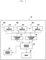
- the gNB 102 includes multiple antennas 205a-205n, multiple RF transceivers 210a-210n, transmit (TX) processing circuitry 215, and receive (RX) processing circuitry 220.
- the gNB 102 also includes a controller/processor 225, a memory 230, and a backhaul or network interface 235.
- the RF transceivers 210a-210n receive, from the antennas 205a-205n, incoming RF signals, such as signals transmitted by UEs in the network 100.
- the RF transceivers 210a-210n down-convert the incoming RF signals to generate IF or baseband signals.
- the IF or baseband signals are sent to the RX processing circuitry 220, which generates processed baseband signals by filtering, decoding, and/or digitizing the baseband or IF signals.
- the RX processing circuitry 220 transmits the processed baseband signals to the controller/processor 225 for further processing.
- the RF transceiver 310 receives, from the antenna 305, an incoming RF signal transmitted by a gNB of the network 100.
- the RF transceiver 310 down-converts the incoming RF signal to generate an intermediate frequency (IF) or baseband signal.
- the IF or baseband signal is sent to the RX processing circuitry 325, which generates a processed baseband signal by filtering, decoding, and/or digitizing the baseband or IF signal.
- the RX processing circuitry 325 transmits the processed baseband signal to the speaker 330 (such as for voice data) or to the processor 340 for further processing (such as for web browsing data).
- the processor 340 is also capable of executing other processes and programs resident in the memory 360, such as processes for beam management.
- the processor 340 can move data into or out of the memory 360 as required by an executing process.
- the processor 340 is configured to execute the applications 362 based on the OS 361 or in response to signals received from gNBs or an operator.
- the processor 340 is also coupled to the I/O interface 345, which provides the UE 116 with the ability to connect to other devices, such as laptop computers and handheld computers.
- the I/O interface 345 is the communication path between these accessories and the processor 340.
- FIGURE 3 illustrates one example of UE 116
- various changes may be made to FIGURE 3 .
- various components in FIGURE 3 could be combined, further subdivided, or omitted and additional components could be added according to particular needs.
- the processor 340 could be divided into multiple processors, such as one or more central processing units (CPUs) and one or more graphics processing units (GPUs).
- FIGURE 3 illustrates the UE 116 configured as a mobile telephone or smartphone, UEs could be configured to operate as other types of mobile or stationary devices.
- a communication system includes a downlink (DL) that refers to transmissions from a base station or one or more transmission points to UEs and an uplink (UL) that refers to transmissions from UEs to a base station or to one or more reception points.
- DL downlink
- UL uplink
- the 5G or pre-5G communication system is also called a "beyond 4G network" or a "post LTE system.”
- the 5G communication system is considered to be implemented in higher frequency (mmWave) bands, e.g., 60GHz bands, so as to accomplish higher data rates.
- mmWave e.g., 60GHz bands
- MIMO massive multiple-input multiple-output
- FD-MIMO full dimensional MIMO
- array antenna an analog beam forming, large scale antenna techniques are discussed in 5G communication systems.
- RANs cloud radio access networks
- D2D device-to-device
- SWSC sliding window superposition coding
- ACM advanced coding modulation
- FBMC filter bank multi carrier
- NOMA non-orthogonal multiple access
- SCMA sparse code multiple access
- a time unit for DL signaling or for UL signaling on a cell is referred to as a slot and can include one or more symbols.
- a symbol can also serve as an additional time unit.
- a frequency (or bandwidth (BW)) unit is referred to as a resource block (RB).
- One RB includes a number of sub-carriers (SCs).
- SCs sub-carriers
- a slot can have duration of 0.5 milliseconds or 1 millisecond, include 7 symbols or 14 symbols, respectively, and an RB can have a BW of 180 kHz or 360 kHz and include 12 SCs with inter-SC spacing of 15 kHz or 30 kHz.
- DL signals include data signals conveying information content, control signals conveying DL control information (DCI), and reference signals (RS) that are also known as pilot signals.
- a gNB can transmit data information or DCI through respective physical DL shared channels (PDSCHs) or physical DL control channels (PDCCHs).
- a gNB can transmit one or more of multiple types of RS including channel state information RS (CSI-RS) and demodulation RS (DMRS).
- CSI-RS channel state information RS
- DMRS demodulation RS
- a CSI-RS is intended for UEs to measure channel state information (CSI) or to perform other measurements such as ones related to mobility support.
- a DMRS can be transmitted only in the BW of a respective PDCCH or PDSCH and a UE can use the DMRS to demodulate data or control information.
- V2X vehicle-to-everything
- V2X vehicle-to-everything
- V2V vehicle-to-vehicle
- V2I vehicle-to-infrastructure
- V2P vehicle-to-pedestrian
- FIGURE 4 illustrates an example use case of a vehicle-centric communication network 400 according to illustrative embodiments of the present disclosure.
- the embodiment of the gNB 102 illustrated in FIGURE 4 is for illustration only.
- FIGURE 4 does not limit the scope of this disclosure to any particular implementation.
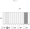
- FIGURE 5 illustrates an example composition of a sidelink synchronization subframe 500 in LTE-V2X according to embodiments of the present disclosure.
- the embodiment of the composition of a sidelink synchronization subframe 500 illustrated in FIGURE 5 is for illustration only.
- FIGURE 5 does not limit the scope of this disclosure to any particular implementation.
- sidelink synchronization is achieved by detecting the sidelink synchronization signals located within the sidelink synchronization subframe.
- An illustration of the composition of a sidelink synchronization subframe is shown in FIGURE 5 , wherein the subframe contains 14 symbols, and 13 of them are mapped for either primary sidelink synchronization signal (PSSS), secondary sidelink synchronization signal (SSSS), physical sidelink broadcast channel (PSBCH), or demodulation reference signal (DMRS).
- PSSS primary sidelink synchronization signal
- SSSS secondary sidelink synchronization signal
- PSBCH physical sidelink broadcast channel
- DMRS demodulation reference signal
- the remaining 1 symbol e.g., the last symbol
- the bandwidth of all signals and channels in the synchronization subframe is 6 RBs, and mapped to the central 6 RBs of the carrier.
- New radio also supports synchronization through synchronization signals transmitted on downlink.
- NR supports larger range of carrier frequencies, and more flexibly numerology.
- NR supports multiple synchronization signals and physical broadcast channel blocks (SS/PBCH block) on each carrier frequency range, wherein each SS/PBCH block compromises of four consecutive orthogonal frequency division multiplexing (OFDM) symbols (see FIGURE 6 ), wherein the first symbol is mapped for primary synchronization signal (PSS), the second and forth symbols are mapped for PBCH, and the third symbol is mapped for both secondary synchronization signal (SSS) and PBCH.
- OFDM orthogonal frequency division multiplexing
- the same SS/PBCH block composition is applied to all supported carrier frequency ranges in NR, which spans from 0 GHz to 52.6 GHz.
- the transmission bandwidth of PSS and SSS e.g., 12 resource blocks (RBs)
- RBs resource blocks
- the transmission bandwidth of PSS and SSS is smaller than the transmission bandwidth of the whole SS/PBCH block (e.g., 20 RBs).
- 3 out of the 12 resource elements (REs) are mapped for the demodulation reference signal (DMRS) of PBCH, wherein the 3 REs are uniformly distributed in the PRB and the starting location of the first RE is based on cell ID.
- DMRS demodulation reference signal
- NR Rel-15 supports one or two subcarrier spacing (SCS) for SS/PBCH block, for a given band, wherein the same SCS is utilized for PSS, SSS, and PBCH (including DMRS).
- SCS subcarrier spacing
- For carrier frequency range 6 GHz to 52.6 GHz, 120 kHz and/or 240 kHz can be utilized for SS SCS.
- the sequence constructing PSS is based on M-sequence with cyclic shifts to represent the cell ID information carried by PSS
- the sequence constructing SSS is based on Gold-sequence (XOR of two M-sequences), wherein each M-sequence constructing the Gold-sequence performs cyclic shift to represent the cell ID information carried by SSS.
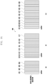
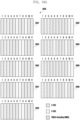
- FIGURE 7 illustrates an example SS/PBCH block mapping patterns with respect to subcarrier spacings 700 according to embodiments of the present disclosure.
- the embodiment of the SS/PBCH block mapping patterns with respect to subcarrier spacings 700 illustrated in FIGURE 7 is for illustration only.
- FIGURE 7 does not limit the scope of this disclosure to any particular implementation.
- SS/PBCH blocks could be transmitted in a beam-sweeping way up to network implementation, and multiple candidate location for transmitting SS/PBCH blocks are predefined within a unit of half frame.
- the mapping pattern of SS/PBCH blocks to 1 slot with respect to 15 kHz as the reference SCS for sub6 GHz and with respect to 60 kHz as the reference SCS for above6 GHz are illustrated in 701 and 702 of FIGURE 7 , respectively.
- Two mapping patterns are designed for 30 kHz SS SCS: Pattern 1 is utilized for non-LTE-NR coexistence bands, and Pattern 2 is utilized for LTE-NR coexistence bands.
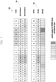
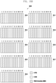
- FIGURE 8 illustrates example SS/PBCH block locations within a half 800 according to embodiments of the present disclosure.
- the embodiment of the SS/PBCH block locations within a half 800 illustrated in FIGURE 8 is for illustration only.
- FIGURE 8 does not limit the scope of this disclosure to any particular implementation.
- L_SSB The maximum number of SS/PBCH blocks, denoted as L_SSB, is determined based on carrier frequency range: for carrier frequency range 0 GHz to 3 GHz, L_SSB is 4; for carrier frequency range 3 GHz to 6 GHz, L_SSB is 8; for carrier frequency range 6 GHz to 52.6 GHz, L_SSB is 64.
- FIGURE 8 The determination of the slots within the half frame unit which contains the candidate locations of SS/PBCH blocks, with respect to each combination of SS SCS and L_SSB, is illustrated in FIGURE 8 .
- UE In initial cell selection, UE assumes a default SS burst set periodicity as 20 ms, and for detecting non-standalone NR cell, network provides one SS burst set periodicity information per frequency carrier to UE and information to derive measurement timing/duration if possible.
- the SS/PBCH block index is indicated by the DMRS of PBCH in the corresponding SS/PBCH block for carrier frequency range 0 to 6 GHz, and the 3 least significant bits (LSBs) of the SS/PBCH block index is indicated by the DMRS of PBCH in the corresponding SS/PBCH block for carrier frequency range 6 GHz to 52.6 GHz (and the 3 most significant bits (MSBs) are indicated by PBCH content).
- LSBs least significant bits
- bit size of PBCH content is 56, including 24 bits CRC.
- a summary of NR 24-bits MIB together with another 8 bits generated in the physical layer is illustrated in TABLE 2, wherein some bit size and corresponding taken values are specified per carrier frequency range. TABLE 2.
- the synchronization signals on NR sidelink can use the synchronization signals on downlink as a baseline, and potential enhancement and/or modification to address the exclusive requirement for V2X can be supported.
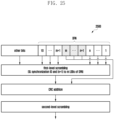
- the present disclosure focuses on the design of sidelink SS/PBCH block (S-SSB), including the S-SSB composition, synchronization signals, content of NR sidelink PBCH (PSBCH), PSBCH scrambling, DMRS of PSBCH, and pre-configured system information.
- S-SSB sidelink SS/PBCH block
- the present disclosure covers several components which can be used in conjunction or in combination with one another, or can operate as standalone schemes.
- NR SS/PBCH block composition (e.g., FIGURE 6 ) can be a starting point for designing the NR sidelink SS and PBCH block (S-SSB). This embodiment details the design aspects for S-SSB composition.
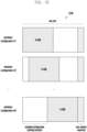
- FIGURE 9A illustrates an example design of an S-SSB 900 according to embodiments of the present disclosure.
- the embodiment of the design of an S-SSB 900 illustrated in FIGURE 9A is for illustration only.
- FIGURE 9A does not limit the scope of this disclosure to any particular implementation.
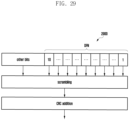
- FIGURE 9B illustrates another example design of an S-SSB 920 according to embodiments of the present disclosure.
- the embodiment of design of an S-SSB 920 illustrated in FIGURE 9B is for illustration only.
- FIGURE 9B does not limit the scope of this disclosure to any particular implementation.
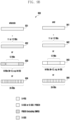
- FIGURE 9A and FIGURE 9B illustrate design examples of an S-SSB.
- An S-SSB can comprise at least one symbol mapped for S-PSS, at least one symbol mapped for PSBCH, and at least one symbol mapped for S-SSS or multiplexing of S-SSS and PSBCH.
- the at least one symbol mapped for S-PSS can be mapped for S-PSS only if the bandwidth of S-SSB is 11 or 12 RBs (942 of FIGURE 9B ).
- the at least one symbol mapped for S-PSS can be mapped for multiplexing of S-PSS and empty REs (e.g., empty REs FDMed with S-PSS) if the bandwidth of S-SSB is larger than 12 RBs (such as 20 RBs) (943 of FIGURE 9B ).
- DMRS of PSBCH can be TDMed with PSBCH.
- some of the symbols in the sub-blocks separated by symbol(s) containing S-PSS or S-SSS (such as 902, 904, 913, 915, 917, 924, 926, 928, 930 in FIGURE 9A ) can be mapped for DMRS of PSBCH, and TDMed with other symbols mapped for PSBCH.
- the S-PSS, S-SSS, and PSBCH are transmitted using the same antenna port.
- FIGURE 10A illustrates an example S-SSB 1000 according to embodiments of the present disclosure.
- the embodiment of the S-SSB 1000 illustrated in FIGURE 10A is for illustration only.
- FIGURE 10A does not limit the scope of this disclosure to any particular implementation.
- FIGURE 12A illustrates yet another example S-SSB 1200 according to embodiments of the present disclosure.
- the embodiment of the S-SSB 1200 illustrated in FIGURE 12A is for illustration only.
- FIGURE 12A does not limit the scope of this disclosure to any particular implementation.
- FIGURE 12C illustrates yet another example S-SSB 1240 according to embodiments of the present disclosure.
- the embodiment of the S-SSB 12illustrated in FIGURE 12C is for illustration only.
- FIGURE 12C does not limit the scope of this disclosure to any particular implementation.
- FIGURE 13A illustrates yet another example S-SSB 1300 according to embodiments of the present disclosure.
- the embodiment of the S-SSB 1300 illustrated in FIGURE 13A is for illustration only.
- FIGURE 13A does not limit the scope of this disclosure to any particular implementation.
- FIGURE 13B illustrates yet another example S-SSB 1320 according to embodiments of the present disclosure.
- the embodiment of the S-SSB 1320 illustrated in FIGURE 13B is for illustration only.
- FIGURE 13B does not limit the scope of this disclosure to any particular implementation.
- FIGURE 14A illustrates yet another example S-SSB 1400 according to embodiments of the present disclosure.
- the embodiment of the S-SSB 1400 illustrated in FIGURE 14A is for illustration only.
- FIGURE 14A does not limit the scope of this disclosure to any particular implementation.
- FIGURE 14C illustrates yet another example S-SSB 1440 according to embodiments of the present disclosure.
- the embodiment of the S-SSB 1440 illustrated in FIGURE 14C is for illustration only.
- FIGURE 14C does not limit the scope of this disclosure to any particular implementation.
- FIGURE 14D illustrates yet another example S-SSB 1460 according to embodiments of the present disclosure.
- the embodiment of the S-SSB 1460 illustrated in FIGURE 14D is for illustration only.
- FIGURE 14D does not limit the scope of this disclosure to any particular implementation.
- FIGURE 14E illustrates yet another example S-SSB 1480 according to embodiments of the present disclosure.
- the embodiment of the S-SSB 1480 illustrated in FIGURE 14E is for illustration only.
- FIGURE 14E does not limit the scope of this disclosure to any particular implementation.
- FIGURE 15A illustrates yet another example S-SSB 1500 according to embodiments of the present disclosure.
- the embodiment of the S-SSB 1500 illustrated in FIGURE 15A is for illustration only.
- FIGURE 15A does not limit the scope of this disclosure to any particular implementation.
- FIGURE 15B illustrates yet another example S-SSB 1520 according to embodiments of the present disclosure.
- the embodiment of the S-SSB 1520 illustrated in FIGURE 15B is for illustration only.
- FIGURE 15B does not limit the scope of this disclosure to any particular implementation.
- FIGURE 15C illustrates yet another example S-SSB 1540 according to embodiments of the present disclosure.
- the embodiment of the S-SSB 1540 illustrated in FIGURE 15C is for illustration only.
- FIGURE 15C does not limit the scope of this disclosure to any particular implementation.
- FIGURE 16A illustrates yet another example S-SSB 1600 according to embodiments of the present disclosure.
- the embodiment of the S-SSB 1600 illustrated in FIGURE 16A is for illustration only.
- FIGURE 16A does not limit the scope of this disclosure to any particular implementation.
- FIGURE 16B illustrates yet another example S-SSB 1620 according to embodiments of the present disclosure.
- the embodiment of the S-SSB 1620 illustrated in FIGURE 16B is for illustration only.
- FIGURE 16B does not limit the scope of this disclosure to any particular implementation.
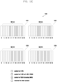
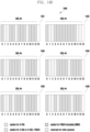
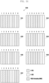
- FIGURE 10A and FIGURE 10B illustrate examples of this embodiment wherein one slot with 14 symbols contains two consecutive PSBCH blocks (SSBs), and two symbols (e.g., the first and last symbols in FIGURE 10A or the seventh and last symbol in FIGURE 10B ) of the slot are reserved for other purpose such as automatic gain control (AGC) or transmission-to-reception (TX/RX) switch gap.
- AGC automatic gain control
- TX/RX transmission-to-reception
- each PSBCH block contains 2 symbols for S-PSS, 2 symbols for S-SSS or multiplexing of S-SSS and PSBCH, and 2 symbols for PSBCH.
- each PSBCH block contains 2 symbols for S-PSS, 1 symbol for S-SSS or multiplexing of S-SSS and PSBCH, and 3 symbols for PSBCH.
- each PSBCH block contains 1 symbol for S-PSS, 2 symbols for S-SSS or multiplexing of S-SSS and PSBCH, and 3 symbols for PSBCH.
- each PSBCH block contains 1 symbol for S-PSS, 1 symbol for S-SSS or multiplexing of S-SSS and PSBCH, and 4 symbols for PSBCH.
- the first and last symbols within a slot are reserved for other purpose, and symbols #1 to #6 are mapped for a first S-SSB within the slot, and symbols #7 to #12 are mapped for a second S-SSB within a slot, wherein the two S-SSBs have the same composition with respect to the time domain mapping: the first and second symbols in the S-SSB (i.e., symbols #1, #2, #7, and #8 in term of the symbol index within the slot) are mapped for S-PSS, the fourth and sixth symbols in the S-SSB (i.e., symbols #4, #6, #10, and #12 in term of the symbol index within the slot) are mapped for S-SSS (if the BW of S-SSB is 12 RBs or 24 RBs) or multiplexing of S-SSS and PSBCH (if the BW of S-SSB is larger than 12 RBs such as 20 RBs), and the third and fifth symbols
- the first and last symbols within a slot are reserved for other purpose, and symbols #1 to #6 are mapped for a first S-SSB within the slot, and symbols #7 to #12 are mapped for a second S-SSB within a slot, wherein the two S-SSBs have the same composition with respect to the time domain mapping: the first and second symbols in the S-SSB (i.e., symbols #1, #2, #7, and #8 in term of the symbol index within the slot) are mapped for S-PSS, the fourth and fifth symbols in the S-SSB (i.e., symbols #4, #6, #10, and #11 in term of the symbol index within the slot) are mapped for S-SSS (if the BW of S-SSB is 12 RBs or 24 RBs) or multiplexing of S-SSS and PSBCH (if the BW of S-SSB is larger than 12 RBs such as 20 RBs), and the third and sixth symbols
- the first and last symbols within a slot are reserved for other purpose, and symbols #1 to #6 are mapped for a first S-SSB within the slot, and symbols #7 to #12 are mapped for a second S-SSB within a slot, wherein the two S-SSBs have the same composition with respect to the time domain mapping: the first symbol in the S-SSB (i.e., symbols #1, and #7 in term of the symbol index within the slot) are mapped for S-PSS, the third and fifth symbols in the S-SSB (i.e., symbols #3, #5, #9, and #11 in term of the symbol index within the slot) are mapped for S-SSS (if the BW of S-SSB is 12 RBs or 24 RBs) or multiplexing of S-SSS and PSBCH (if the BW of S-SSB is larger than 12 RBs such as 20 RBs), and the second, fourth, and sixth symbols in the S
- the first and last symbols within a slot are reserved for other purpose, and symbols #1 to #6 are mapped for a first S-SSB within the slot, and symbols #7 to #12 are mapped for a second S-SSB within a slot, wherein the two S-SSBs have the same composition with respect to the time domain mapping: the second symbol in the S-SSB (i.e., symbols #2, and #8 in term of the symbol index within the slot) are mapped for S-PSS, the fourth and fifth symbols in the S-SSB (i.e., symbols #4, #5, #10, and #11 in term of the symbol index within the slot) are mapped for S-SSS (if the BW of S-SSB is 12 RBs or 24 RBs) or multiplexing of S-SSS and PSBCH (if the BW of S-SSB is larger than 12 RBs such as 20 RBs), and the first, third, and sixth symbols in the S
- the first and last symbols within a slot are reserved for other purpose, and symbols #1 to #6 are mapped for a first S-SSB within the slot, and symbols #7 to #12 are mapped for a second S-SSB within a slot, wherein the two S-SSBs have the same composition with respect to the time domain mapping: the second symbol in the S-SSB (i.e., symbols #2, and #8 in term of the symbol index within the slot) are mapped for S-PSS, the fourth and sixth symbols in the S-SSB (i.e., symbols #4, #6, #10, and #12 in term of the symbol index within the slot) are mapped for S-SSS (if the BW of S-SSB is 12 RBs or 24 RBs) or multiplexing of S-SSS and PSBCH (if the BW of S-SSB is larger than 12 RBs such as 20 RBs), and the first, third, and fifth symbols in the S
- the first and last symbols within a slot are reserved for other purpose, and symbols #1 to #6 are mapped for a first S-SSB within the slot, and symbols #7 to #12 are mapped for a second S-SSB within a slot, wherein the two S-SSBs have the same composition with respect to the time domain mapping: the first and second symbol in the S-SSB (i.e., symbols #1, #2, #7, and #8 in term of the symbol index within the slot) are mapped for S-PSS, the fourth symbol in the S-SSB (i.e., symbols #4, and #10 in term of the symbol index within the slot) are mapped for S-SSS (if the BW of S-SSB is 12 RBs or 24 RBs) or multiplexing of S-SSS and PSBCH (if the BW of S-SSB is larger than 12 RBs such as 20 RBs), and the third, fifth, and sixth symbols in the S
- the first and last symbols within a slot are reserved for other purpose, and symbols #1 to #6 are mapped for a first S-SSB within the slot, and symbols #7 to #12 are mapped for a second S-SSB within a slot, wherein the two S-SSBs have the same composition with respect to the time domain mapping: the second symbol in the S-SSB (i.e., symbols #2, and #8 in term of the symbol index within the slot) are mapped for S-PSS, the fourth symbol in the S-SSB (i.e., symbols #4, and #10 in term of the symbol index within the slot) are mapped for S-SSS (if the BW of S-SSB is 12 RBs or 24 RBs) or multiplexing of S-SSS and PSBCH (if the BW of S-SSB is larger than 12 RBs such as 20 RBs), and the first, third, fifth, and sixth symbols in the S-SSB (i
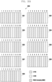
- the seventh and last symbols within a slot are reserved for other purpose, and symbols #0 to #5 are mapped for a first S-SSB within the slot, and symbols #7 to #12 are mapped for a second S-SSB within a slot, wherein the two S-SSBs have the same composition with respect to the time domain mapping: the first and second symbol in the S-SSB (i.e., symbols #0, #1, #7, and #8 in term of the symbol index within the slot) are mapped for S-PSS, the fourth and sixth symbol in the S-SSB (i.e., symbols #3, #5, #10, and #12 in term of the symbol index within the slot) are mapped for S-SSS (if the BW of S-SSB is 12 RBs or 24 RBs) or multiplexing of S-SSS and PSBCH (if the BW of S-SSB is larger than 12 RBs such as 20 RBs), and the third
- the seventh and last symbols within a slot are reserved for other purpose, and symbols #0 to #5 are mapped for a first S-SSB within the slot, and symbols #7 to #12 are mapped for a second S-SSB within a slot, wherein the two S-SSBs have the same composition with respect to the time domain mapping: the first and second symbol in the S-SSB (i.e., symbols #0, #1, #7, and #8 in term of the symbol index within the slot) are mapped for S-PSS, the fourth and fifth symbol in the S-SSB (i.e., symbols #3, #4, #10, and #11 in term of the symbol index within the slot) are mapped for S-SSS (if the BW of S-SSB is 12 RBs or 24 RBs) or multiplexing of S-SSS and PSBCH (if the BW of S-SSB is larger than 12 RBs such as 20 RBs), and the third
- the seventh and last symbols within a slot are reserved for other purpose, and symbols #0 to #5 are mapped for a first S-SSB within the slot, and symbols #7 to #12 are mapped for a second S-SSB within a slot, wherein the two S-SSBs have the same composition with respect to the time domain mapping: the second and third symbol in the S-SSB (i.e., symbols #1, #2, #8, and #9 in term of the symbol index within the slot) are mapped for S-PSS, the fifth symbol in the S-SSB (i.e., symbols #4, and #11 in term of the symbol index within the slot) are mapped for S-SSS (if the BW of S-SSB is 12 RBs or 24 RBs) or multiplexing of S-SSS and PSBCH (if the BW of S-SSB is larger than 12 RBs such as 20 RBs), and the first, fourth, and sixth symbols in the S
- the seventh and last symbols within a slot are reserved for other purpose, and symbols #0 to #5 are mapped for a first S-SSB within the slot, and symbols #7 to #12 are mapped for a second S-SSB within a slot, wherein the two S-SSBs have the same composition with respect to the time domain mapping: the second symbol in the S-SSB (i.e., symbols #1, and #8 in term of the symbol index within the slot) are mapped for S-PSS, the fourth and fifth symbol in the S-SSB (i.e., symbols #3, #4, #10, and #11 in term of the symbol index within the slot) are mapped for S-SSS (if the BW of S-SSB is 12 RBs or 24 RBs) or multiplexing of S-SSS and PSBCH (if the BW of S-SSB is larger than 12 RBs such as 20 RBs), and the first, third, and sixth symbols in the
- the seventh and last symbols within a slot are reserved for other purpose, and symbols #0 to #5 are mapped for a first S-SSB within the slot, and symbols #7 to #12 are mapped for a second S-SSB within a slot, wherein the two S-SSBs have the same composition with respect to the time domain mapping: the second symbol in the S-SSB (i.e., symbols #1, and #8 in term of the symbol index within the slot) are mapped for S-PSS, the third and fifth symbol in the S-SSB (i.e., symbols #2, #4, #9, and #11 in term of the symbol index within the slot) are mapped for S-SSS (if the BW of S-SSB is 12 RBs or 24 RBs) or multiplexing of S-SSS and PSBCH (if the BW of S-SSB is larger than 12 RBs such as 20 RBs), and the first, fourth, and sixth symbols in the
- the seventh and last symbols within a slot are reserved for other purpose, and symbols #0 to #5 are mapped for a first S-SSB within the slot, and symbols #7 to #12 are mapped for a second S-SSB within a slot, wherein the two S-SSBs have the same composition with respect to the time domain mapping: the second symbol in the S-SSB (i.e., symbols #1, and #8 in term of the symbol index within the slot) are mapped for S-PSS, the fourth symbol in the S-SSB (i.e., symbols #3, and #10 in term of the symbol index within the slot) are mapped for S-SSS (if the BW of S-SSB is 12 RBs or 24 RBs) or multiplexing of S-SSS and PSBCH (if the BW of S-SSB is larger than 12 RBs such as 20 RBs), and the first, third, fifth, and sixth symbols in the S-SSB (
- the seventh and last symbols within a slot are reserved for other purpose, and symbols #0 to #5 are mapped for a first S-SSB within the slot, and symbols #7 to #12 are mapped for a second S-SSB within a slot, wherein the two S-SSBs have the same composition with respect to the time domain mapping: the second symbol in the S-SSB (i.e., symbols #1, and #8 in term of the symbol index within the slot) are mapped for S-PSS, the fifth symbol in the S-SSB (i.e., symbols #4, and #11 in term of the symbol index within the slot) are mapped for S-SSS (if the BW of S-SSB is 12 RBs or 24 RBs) or multiplexing of S-SSS and PSBCH (if the BW of S-SSB is larger than 12 RBs such as 20 RBs), and the first, third, fourth, and sixth symbols in the S-SSB (
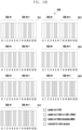
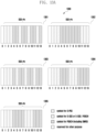
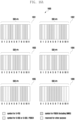
- FIGURE 11 illustrates examples of this embodiment wherein one slot with 14 symbols contains two consecutive PSBCH blocks (SSBs), and each PSBCH block contains 7 symbols, and no symbol in the slot is reserved for other purpose.
- each PSBCH block contains 2 symbols for S-PSS, 2 symbols for S-SSS or multiplexing of S-SSS and PSBCH, and 3 symbols for PSBCH.
- symbols #0 to #6 are mapped for a first S-SSB within the slot
- symbols #7 to #13 are mapped for a second S-SSB within a slot
- the two S-SSBs have the same composition with respect to the time domain mapping: the first and second symbols in the S-SSB (i.e., symbols #0, #1, #7, and #8 in term of the symbol index within the slot) are mapped for S-PSS, the fourth and sixth symbols in the S-SSB (i.e., symbols #3, #5, #10, and #12 in term of the symbol index within the slot) are mapped for S-SSS (if the BW of S-SSB is 12 RBs or 24 RBs) or multiplexing of S-SSS and PSBCH (if the BW of S-SSB is larger than 12 RBs such as 20 RBs), and the third, fifth, and seventh symbols in the S-SSB (i.e.
- symbols #0 to #6 are mapped for a first S-SSB within the slot
- symbols #7 to #13 are mapped for a second S-SSB within a slot
- the two S-SSBs have the same composition with respect to the time domain mapping: the first and second symbols in the S-SSB (i.e., symbols #0, #1, #7, and #8 in term of the symbol index within the slot) are mapped for S-PSS, the sixth and seventh symbols in the S-SSB (i.e., symbols #5, #6, #12, and #13 in term of the symbol index within the slot) are mapped for S-SSS (if the BW of S-SSB is 12 RBs or 24 RBs) or multiplexing of S-SSS and PSBCH (if the BW of S-SSB is larger than 12 RBs such as 20 RBs), and the third, fourth, and fifth symbols in the S-SSB (i.e.,
- symbols #0 to #6 are mapped for a first S-SSB within the slot
- symbols #7 to #13 are mapped for a second S-SSB within a slot
- the two S-SSBs have the same composition with respect to the time domain mapping: the second and third symbols in the S-SSB (i.e., symbols #1, #2, #8, and #9 in term of the symbol index within the slot) are mapped for S-PSS, the fifth and sixth symbols in the S-SSB (i.e., symbols #4, #5, #11, and #12 in term of the symbol index within the slot) are mapped for S-SSS (if the BW of S-SSB is 12 RBs or 24 RBs) or multiplexing of S-SSS and PSBCH (if the BW of S-SSB is larger than 12 RBs such as 20 RBs), and the first, fourth, and seventh symbols in the S-SSB (i.e., symbols #
- symbols #0 to #6 are mapped for a first S-SSB within the slot
- symbols #7 to #13 are mapped for a second S-SSB within a slot
- the two S-SSBs have the same composition with respect to the time domain mapping: the second and third symbols in the S-SSB (i.e., symbols #1, #2, #8, and #9 in term of the symbol index within the slot) are mapped for S-PSS, the fifth and seventh symbols in the S-SSB (i.e., symbols #4, #6, #11, and #13 in term of the symbol index within the slot) are mapped for S-SSS (if the BW of S-SSB is 12 RBs or 24 RBs) or multiplexing of S-SSS and PSBCH (if the BW of S-SSB is larger than 12 RBs such as 20 RBs), and the first, fourth, and sixth symbols in the S-SSB (i.e., symbols #
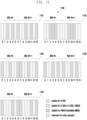
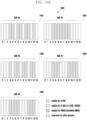
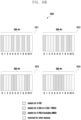
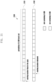
- symbols #1 to #12 are mapped for the S-SSB within the slot, wherein: the first, second, and third symbols in the S-SSB (i.e., symbols #1, #2, and #3 in term of the symbol index within the slot) are mapped for S-PSS, the sixth, ninth, and twelfth symbols in the S-SSB (i.e., symbols #6, #9, and #12 in term of the symbol index within the slot) are mapped for S-SSS (if the BW of S-SSB is 12 RBs or 24 RBs) or multiplexing of S-SSS and PSBCH (if the BW of S-SSB is larger than 12 RBs such as 20 RBs), and the fourth, fifth, seventh, eighth, tenth, and eleventh symbols in the S-SSB (i.e., symbols #4, #5, #7, #8, #10, and #11 in term of the symbol index within the slot) are mapped for PS
- symbols #1 to #12 are mapped for the S-SSB within the slot, wherein: the first, second, and third symbols in the S-SSB (i.e., symbols #1, #2, and #3 in term of the symbol index within the slot) are mapped for S-PSS, the tenth, eleventh, and twelfth symbols in the S-SSB (i.e., symbols #10, #11, and #12 in term of the symbol index within the slot) are mapped for S-SSS (if the BW of S-SSB is 12 RBs or 24 RBs) or multiplexing of S-SSS and PSBCH (if the BW of S-SSB is larger than 12 RBs such as 20 RBs), and the fourth, fifth, sixth, seventh, eighth, and ninth symbols in the S-SSB (i.e., symbols #4, #5, #6, #7, #8, and #9 in term of the symbol index within the slot) are mapped for PSB
- symbols #1 to #12 are mapped for the S-SSB within the slot, wherein: the first, and second symbols in the S-SSB (i.e., symbols #1, and #2 in term of the symbol index within the slot) are mapped for S-PSS, the sixth, and ninth symbols in the S-SSB (i.e., symbols #6, and #9 in term of the symbol index within the slot) are mapped for S-SSS (if the BW of S-SSB is 12 RBs or 24 RBs) or multiplexing of S-SSS and PSBCH (if the BW of S-SSB is larger than 12 RBs such as 20 RBs), and the third, fourth, fifth, seventh, eighth, tenth, eleventh, and twelfth symbols in the S-SSB (i.e., symbols #3, #4, #5, #7, #8, #10, #11, and #12 in term of the symbol index within the slot) are mapped for PS
- symbols #1 to #12 are mapped for the S-SSB within the slot, wherein: the first, and second symbols in the S-SSB (i.e., symbols #1, and #2 in term of the symbol index within the slot) are mapped for S-PSS, the fifth, and tenth symbols in the S-SSB (i.e., symbols #5, and #10 in term of the symbol index within the slot) are mapped for S-SSS (if the BW of S-SSB is 12 RBs or 24 RBs) or multiplexing of S-SSS and PSBCH (if the BW of S-SSB is larger than 12 RBs such as 20 RBs), and the third, fourth, sixth, seventh, eighth, ninth, eleventh, and twelfth symbols in the S-SSB (i.e., symbols #3, #4, #6, #7, #8, #9, #11, and #12 in term of the symbol index within the slot) are mapped for PS
- symbols #1 to #12 are mapped for the S-SSB within the slot, wherein: the first, and second symbols in the S-SSB (i.e., symbols #1, and #2 in term of the symbol index within the slot) are mapped for S-PSS, the seventh, and eighth symbols in the S-SSB (i.e., symbols #7, and #8 in term of the symbol index within the slot) are mapped for S-SSS (if the BW of S-SSB is 12 RBs or 24 RBs) or multiplexing of S-SSS and PSBCH (if the BW of S-SSB is larger than 12 RBs such as 20 RBs), and the third, fourth, fifth, sixth, ninth, tenth, eleventh, and twelfth symbols in the S-SSB (i.e., symbols #3, #4, #6, #7, #8, #9, #11, and #12 in term of the symbol index within the slot) are mapped for
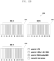
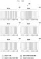
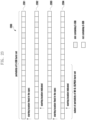
- symbols #0 to #12 are mapped for the S-SSB within the slot, wherein: the first, second, third, and fourth symbols in the S-SSB (i.e., symbols #0, #1, #2, and #3 in term of the symbol index within the slot) are mapped for S-PSS, the sixth, seventh, eleventh, and twelfth symbols in the S-SSB (i.e., symbols #5, #6, #10, and #11 in term of the symbol index within the slot) are mapped for S-SSS (if the BW of S-SSB is 12 RBs or 24 RBs) or multiplexing of S-SSS and PSBCH (if the BW of S-SSB is larger than 12 RBs such as 20 RBs), and the fifth, eighth, ninth, tenth, and thirteenth symbols in the S-SSB (i.e., symbols #4, #7, #8, #9, and #12 in term of the symbol index within
- symbols #0 to #12 are mapped for the S-SSB within the slot, wherein: the second, third, and fourth symbols in the S-SSB (i.e., symbols #1, #2, and #3 in term of the symbol index within the slot) are mapped for S-PSS, the fifth, eighth, and eleventh symbols in the S-SSB (i.e., symbols #4, #7, and #10 in term of the symbol index within the slot) are mapped for S-SSS (if the BW of S-SSB is 12 RBs or 24 RBs) or multiplexing of S-SSS and PSBCH (if the BW of S-SSB is larger than 12 RBs such as 20 RBs), and the first, sixth, seventh, ninth, tenth, twelfth, and thirteenth symbols in the S-SSB (i.e., symbols #0, #5, #6, #8, #9, #11, and #12 in term of the symbol index within the
- symbols #0 to #12 are mapped for the S-SSB within the slot, wherein: the second, and third symbols in the S-SSB (i.e., symbols #1, and #2 in term of the symbol index within the slot) are mapped for S-PSS, the fifth, and tenth symbols in the S-SSB (i.e., symbols #4, and #9 in term of the symbol index within the slot) are mapped for S-SSS (if the BW of S-SSB is 12 RBs or 24 RBs) or multiplexing of S-SSS and PSBCH (if the BW of S-SSB is larger than 12 RBs such as 20 RBs), and the first, fourth, sixth, seventh, eighth, ninth, eleventh, twelfth, and thirteenth symbols in the S-SSB (i.e., symbols #0, #3, #5, #6, #7, #8, #10, #11, and #12 in term of the symbol index within the
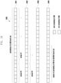
- symbols #0 to #13 are mapped for the S-SSB within the slot, wherein: the second, third, fourth, and fifth symbols in the S-SSB (i.e., symbols #1, #2, #3, and #4 in term of the symbol index within the slot) are mapped for S-PSS, the seventh, eighth, eleventh, and twelfth symbols in the S-SSB (i.e., symbols #6, #7, #10, and #11 in term of the symbol index within the slot) are mapped for S-SSS (if the BW of S-SSB is 12 RBs or 24 RBs) or multiplexing of S-SSS and PSBCH (if the BW of S-SSB is larger than 12 RBs such as 20 RBs), and the first, sixth, ninth, tenth, thirteenth, and fourteenth symbols in the S-SSB (i.e., symbols #0, #5, #8, #9, #12, and #13 in term
- symbols #0 to #10 are mapped for the S-SSB within the slot, wherein: the second, and third symbols in the S-SSB (i.e., symbols #1, and #2 in term of the symbol index within the slot) are mapped for S-PSS, the sixth, and ninth symbols in the S-SSB (i.e., symbols #5, and #8 in term of the symbol index within the slot) are mapped for S-SSS (if the BW of S-SSB is 12 RBs or 24 RBs) or multiplexing of S-SSS and PSBCH (if the BW of S-SSB is larger than 12 RBs such as 20 RBs), and the first, fourth, fifth, seventh, eighth, tenth, and eleventh symbols in the S-SSB (i.e., symbols #0, #3, #4, #6, #7, #9, and #10 in term of the symbol index within the slot) are mapped for PSBCH.
- the second, and third symbols in the S-SSB i.e., symbols
- symbols #0 to #10 are mapped for the S-SSB within the slot, wherein: the second, third, and fourth symbols in the S-SSB (i.e., symbols #1, #2, and #3 in term of the symbol index within the slot) are mapped for S-PSS, the fifth, seventh, and ninth symbols in the S-SSB (i.e., symbols #4, #6, and #8 in term of the symbol index within the slot) are mapped for S-SSS (if the BW of S-SSB is 12 RBs or 24 RBs) or multiplexing of S-SSS and PSBCH (if the BW of S-SSB is larger than 12 RBs such as 20 RBs), and the first, sixth, eighth, tenth, and eleventh symbols in the S-SSB (i.e., symbols #0, #5, #7, #9, and #10 in term of the symbol index within the slot) are mapped for PSBCH.
- the second, third, and fourth symbols in the S-SSB i.e.
- symbols #0 to #10 are mapped for the S-SSB within the slot, wherein: the second, third, and fourth symbols in the S-SSB (i.e., symbols #1, #2, and #3 in term of the symbol index within the slot) are mapped for S-PSS, the seventh, eighth, and ninth symbols in the S-SSB (i.e., symbols #6, #7, and #8 in term of the symbol index within the slot) are mapped for S-SSS (if the BW of S-SSB is 12 RBs or 24 RBs) or multiplexing of S-SSS and PSBCH (if the BW of S-SSB is larger than 12 RBs such as 20 RBs), and the first, fifth, sixth, tenth, and eleventh symbols in the S-SSB (i.e., symbols #0, #4, #5, #9, and #10 in term of the symbol index within the slot) are mapped for PSBCH.
- the second, third, and fourth symbols in the S-SSB i.e.
- contiguous slots containing an S-SSB burst set can be mapped from a predefined location, such as the beginning of the period for transmitting the S-SSB burst set.
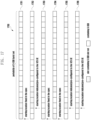
- FIGURE 17 illustrates an example time-domain mapping of an S-SSB burst set 1700 according to embodiments of the present disclosure.
- the embodiment of the time-domain mapping of an S-SSB burst set 1700 illustrated in FIGURE 17 is for illustration only.
- FIGURE 17 does not limit the scope of this disclosure to any particular implementation.
- contiguous slots containing an S-SSB burst set can be mapped from starting from any slot within the period for transmitting the S-SSB burst set.
- the starting location of the S-SSB burst set e.g., slot index within the period
- the V2X UE such as using synchronization signals, or PBCH content, or DMRS of PBCH, or their combination
- the contiguous slots containing an S-SSB burst set can be starting from any slot within the N slots (e.g., slots #S, #S+1, ..., #S+M-1), and the starting location (e.g., information about slot S) can be indicated to the V2X UE (e.g., in the form of a slot index, or a combination of system frame number (SFN) / direct frame number (DFN) and a slot index within the indicated SFN/DFN), such as using synchronization signals, or PBCH content, or DMRS of PBCH, or their combination, or can be pre-configured to the V2X UE.
- the V2X UE e.g., in the form of a slot index, or a combination of system frame number (SFN) / direct frame number (DFN) and a slot index within the indicated SFN/DFN
- the contiguous slots containing an S-SSB burst set can be starting from any frame boundary, and the starting location (e.g., information about slot S) can be indicated to the V2X UE (e.g., in the form of a system frame number (SFN) / direct frame number (DFN)), such as using synchronization signals, or PBCH content, or DMRS of PBCH, or their combination, or can be pre-configured to the V2X UE.
- SFN system frame number
- DNN direct frame number
- the contiguous slots containing an S-SSB burst set can be starting from any half frame boundary, and the starting location (e.g., information about slot S) can be indicated to the V2X UE (e.g., in the form of half frame index within a system frame number (SFN) / direct frame number (DFN) and the SFN/DFN), such as using synchronization signals, or PBCH content, or DMRS of PBCH, or their combination, or can be pre-configured to the V2X UE.
- SFN system frame number
- DNN direct frame number
- DMRS DMRS of PBCH
- slots containing an S-SSB burst set can be non-contiguous.
- every transmission of the S-SSB burst set only has one slot, and the multiple slots containing an S-SSB burst set can be with uniform interval within the period of the S-SSB burst set.
- the slots containing S-SSBs can be uniformly distributed within the whole period duration, e.g., the slots containing S-SSBs are #0, #(N/M), #2*(N/M), ..., #(M-1)*(N/M).
- the slots containing S-SSBs can be uniformly distributed within the whole period duration, and the starting slot can be any viable and indicated to the V2X UE, e.g., the slots containing S-SSBs are #X, #X+(N/M), #X+2*(N/M), ..., #X+(M-1)*(N/M), wherein X is the starting location and can be indicated to the V2X UE (e.g., in the form of a slot index, or a combination of SFN/DFN and a slot index within the indicated SFN/DFN), such as using synchronization signals, or PBCH content, or DMRS of PBCH, or their combination, or can be pre-configured to the V2X UE.
- the slots containing S-SSBs can be uniformly distributed within a subset of the period duration, and the starting slot can be any viable and indicated to the V2X UE, e.g., the slots containing S-SSBs are #X, #X+(N/K), #X+2*(N/K), ..., #X+(M-1)*(N/K), wherein K is a predefined value and K>M, and X is the starting location and can be indicated to the V2X UE (e.g., in the form of a slot index, or a combination of SFN/DFN and a slot index within the indicated SFN/DFN), such as using synchronization signals, or PBCH content, or DMRS of PBCH, or their combination, or can
- design of S-PSS sequence can be combined with examples in the other embodiments of this disclosure.
- the single sequence constructing S-PSS is one of the sequences constructing NR-PSS (e.g., choosing 1 from the 3 sequences constructing NR-PSS).
- the single sequence constructing S-PSS is orthogonal or with low cross-correlation to all the sequences constructing NR-PSS.
- the single sequence constructing the S-PSS in different symbols is different, and the sequences constructing S-PSSs are from the set or a subset of the set of the sequences constructing NR-PSS (e.g., choosing 2 or 3 from the 3 sequences constructing NR-PSS).
- the single sequence constructing the S-PSS in different symbols is different, and some of the sequences constructing S-PSSs in one symbol is from the set or a subset of the set of the sequences constructing NR-PSS (e.g., choosing 1 or 2 or 3 from the 3 sequences constructing NR-PSS), and the others are orthogonal or with low cross-correlation to the sequence from the subset of the sequences constructing NR-PSS.
- a fifth example of this approach when there are multiple symbols mapped for S-PSS within a S-SSB, the single sequence constructing the S-PSS in different symbols is different, and none of the sequences constructing S-PSSs is from the set of sequences constructing NR-PSS, and all the sequences are orthogonal or with low cross-correlation to all the sequences constructing NR-PSS.
- the single sequence constructing the S-PSS in different symbols is the same, but mapped in different pattern to the symbols for S-PSS.
- the single sequence constructing S-PSS is mapped in low-to-high order in the frequency domain in some of the symbols for S-PSS, and mapped in high-to-low order in the frequency domain in the other symbol for S-PSS.
- the single sequence constructing the S-PSS in different symbols is the same, and mapped to the symbols for S-PSS in the same pattern (e.g., the symbols for S-PSS (not including CP) are repeated).
- the single sequence for S-PSS can be generated for and mapped to all the symbols for S-PSS.
- the sequence constructing S-PSS can be used to identify the group index within two groups of the sidelink synchronization IDs.
- the synchronization source is from NR nodes or LTE node.
- the synchronization source is within the coverage of gNB/eNB or not.
- the synchronization source is a NodeB or UE.
- the synchronization source is either one of within the coverage of a gNB/eNB or GNSS, or out of the coverage of a gNB/eNB.
- the synchronization source is either within the coverage of a gNB/eNB, or one of out of the coverage of a gNB/eNB or GNSS.
- the size of two groups can be identical (e.g., easy for S-SSS sequence design).
- the size of two groups can be not identical (e.g., if the two groups of IDs are referring to out of gNB/eNB coverage and within gNB/eNB coverage, the number of IDs in each group may not be the same regarding the use case of each group).
- the set of sequences constructing S-PSS is a subset of the sequences constructing NR-PSS (e.g., choosing 2 from the 3 sequences constructing NR-PSS).
- the sets of sequences constructing the S-PSS in different symbols are different, and the sets of sequences constructing S-PSSs in different symbols are orthogonal or with low cross-correlation across the sets.
- one set of sequences constructing S-PSS for some of the symbols is a subset of the sequences constructing NR-PSS (e.g., choosing 2 from the 3 sequences constructing NR-PSS), and the remaining set(s) of sequences are not from the set of sequences constructing NR-PSS and orthogonal or with low cross-correlation to the set of sequences constructing NR-PSS.
- the sets of sequences constructing the S-PSS in different symbols are different, and the sets of sequences constructing S-PSSs in different symbols are orthogonal or with low cross-correlation across the sets.
- none of the sequences constructing S-PSSs is from the set of sequences constructing NR-PSS, and orthogonal or with low cross-correlation to all the sequences constructing NR-PSS.
- the set of sequences constructing the S-PSS in different symbols is the same, but mapped in different pattern to the symbols for S-PSS.
- the sequence constructing S-PSS is mapped in low-to-high order in the frequency domain in one of the symbols for S-PSS, and mapped in high-to-low order in the frequency domain in the other symbol for S-PSS.
- the set of sequences constructing the S-PSS in different symbols is the same, and mapped to the symbols for S-PSS in the same pattern (e.g., the symbols for S-PSS (not including CP) are repeated).
- each of the two sequences for S-PSS can be generated for and mapped to all the symbols for S-PSS.
- the sequence constructing S-PSS can be used to identify the sidelink synchronization ID group index.
- NR gNB For one example on the three groups, it can be referred that different type of synchronization source are considered, e.g., NR gNB, NR UE, or LTE eNB.
- the number of sidelink synchronization IDs within each group is identical (e.g., easy for S-SSS sequence design), and each of the group refers to a particular use case.
- the number of sidelink synchronization IDs within each group is identical (e.g., easy for S-SSS sequence design), and two groups refer to a use case while the other group refers to another use case (e.g., 2 groups for within gNB coverage and 1 group for out of gNB/eNB coverage, or 1 group for within gNB/eNB coverage and 2 groups for out of gNB/eNB coverage).
- the number of sidelink synchronization IDs within each group is not identical (e.g., if the three groups of IDs are referring to different use cases, the number of IDs in each group may not be the same regarding the use case of each group).
- the set of sequences constructing S-PSS is the set of the sequences constructing NR-PSS (e.g., choosing the 3 sequences constructing NR-PSS).
- the sets of sequences constructing the S-PSS in different symbols are different, and the sets of sequences constructing S-PSSs in different symbols are orthogonal or with low cross-correlation across the sets.
- one set of sequences constructing S-PSS for some of the symbols is from the set of sequences constructing NR-PSS (e.g., choosing the 3 sequences constructing NR-PSS), and the remaining set(s) of sequences are not from the set of sequences constructing NR-PSS and orthogonal or with low cross-correlation to the set of sequences constructing NR-PSS.
- the sets of sequences constructing the S-PSS in different symbols are different, and the sets of sequences constructing S-PSSs in different symbols are orthogonal or with low cross-correlation across the sets.
- none of the sequences constructing S-PSSs is from the set of sequences constructing NR-PSS, and orthogonal or with low cross-correlation to all the sequences constructing NR-PSS.
- the set of sequences constructing the S-PSS in different symbols is the same, but mapped in different pattern to the symbols for S-PSS.
- the sequence constructing S-PSS is mapped in low-to-high order in the frequency domain in one of the symbols for S-PSS, and mapped in high-to-low order in the frequency domain in the other symbol for S-PSS.
- the set of sequences constructing the S-PSS in different symbols is the same, and mapped to the symbols for S-PSS in the same pattern (e.g., the symbols for S-PSS (not including CP) are repeated).
- each of the three sequences for S-PSS can be generated for and mapped to all the symbols for S-PSS.
- sequences constructing S-PSS are illustrated in details as follows, wherein the sequence design reflects the above approaches in this embodiment. There can be multiple examples utilized simultaneously (e.g., one example mapped for one symbol for S-PSS, and another example mapped for another symbol for S-PSS).
- the SL synchronization ID group index N_GID ⁇ SL 0.
- the SL synchronization ID group index N_GID ⁇ SL is 0 or 1.
- the SL synchronization ID group index N_GID ⁇ SL is 0 or 1 or 2.
- the SL synchronization ID group index N_GID ⁇ SL 0.
- the SL synchronization ID group index N_GID ⁇ SL is 0 or 1.
- the SL synchronization ID group index N_GID ⁇ SL is 0 or 1 or 2.
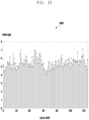
- FIGURE 18 illustrates an example PAPR value of S-PSS sequences 1800 according to embodiments of the present disclosure.
- the embodiment of the PAPR value of S-PSS sequences 1800 illustrated in FIGURE 18 is for illustration only.
- FIGURE 18 does not limit the scope of this disclosure to any particular implementation.
- FIGURE 19 illustrates another example PAPR value of S-PSS sequences 1900 according to embodiments of the present disclosure.
- the embodiment of the PAPR value of S-PSS sequences 1900 illustrated in FIGURE 19 is for illustration only.
- FIGURE 19 does not limit the scope of this disclosure to any particular implementation.
- FIGURE 20 illustrates yet another example PAPR value of S-PSS sequences2000 according to embodiments of the present disclosure.
- the embodiment of the PAPR value of S-PSS sequences2000 illustrated in FIGURE 20 is for illustration only.
- FIGURE 20 does not limit the scope of this disclosure to any particular implementation.
- the SL synchronization ID group index N_GID ⁇ SL is 0 or 1. Then, K_1 is taking one of two candidate predefined integer values, depending on the value of N_GID ⁇ SL.
- the SL synchronization ID group index N_GID ⁇ SL is 0 or 1 or 2.
- K_1 can be chosen to minimize the PAPR values of the S-PSS sequences.
- the SL synchronization ID group index N_GID ⁇ SL 0.
- the SL synchronization ID group index N_GID ⁇ SL is 0 or 1.
- the SL synchronization ID group index N_GID ⁇ SL is 0 or 1 or 2.
- the SL synchronization ID group index N_GID ⁇ SL is 0 or 1.
- the SL synchronization ID group index N_GID ⁇ SL is 0 or 1 or 2.
- design of S-SSS sequence can be combined with examples in the other embodiments of this disclosure.
- the number of sequences constructing S-SSS within each symbol is the same as the number of sidelink synchronization IDs (e.g., every sidelink synchronization ID is mapped to a unique sequence for S-SSS within each symbol mapped for S-SSS).
- the set of sequences constructing S-SSS is a subset of sequences constructing NR-SSS, if the number of sequences for S-SSS is smaller or equal to 1008.
- the set of sequences constructing S-SSS is different from the set of sequences constructing NR-SSS, e.g., by using at least one different M-sequence generator polynomial and/or cyclic shifts.
- the sequences constructing the S-SSS in different symbols can be the same, and mapped in different pattern to the symbols for S-SSS.
- the sequence constructing S-SSS is mapped in low-to-high order in the frequency domain in one of the symbols for S-SSS, and mapped in high-to-low order in the frequency domain in the other symbol for S-SSS.
- the sequences constructing the S-SSS in different symbols can be the same, and mapped to the symbols for S-SSS in the same pattern (e.g., the symbols for S-SSS (not including CP) are repeated.
- the sequences constructing the S-SSS in one symbol can be different from the sequences constructing the S-SSS in another symbol, and mapped to the symbols for S-SSS in the same pattern (e.g., time-frequency domain mapping order), where the sequences in each symbol can be using the sequences in the first or second example of this approach.
- one way to achieve different set of sequences in different symbols is using cover code (i.e., the sequences constructing the S-SSS in one symbol can be the sequences constructing the S-SSS in another symbol with a cover code), and another way to achieve different set of sequences in different symbols is using different generator polynomials and/or different cyclic shifts.
- the sequences constructing the S-SSS in one symbol can be different from the sequences constructing the S-SSS in another symbol, and mapped in different pattern to the symbols for S-SSS, where the sequences in each symbol can be using the sequences in the first or second example of this approach.
- the sequence constructing S-SSS is mapped in low-to-high order in the frequency domain in some of the symbols for S-SSS, and mapped in high-to-low order in the frequency domain in the other symbols for S-SSS.
- one way to achieve different set of sequences in different symbols is using cover code (i.e., the sequences constructing the S-SSS in one symbol can be the sequences constructing the S-SSS in another symbol with a cover code), and another way to achieve different set of sequences in different symbols is using different generator polynomials and/or different cyclic shifts.
- each of the sequences for S-SSS can be generated for and mapped to all the symbols for S-SSS.
- sequences constructing S-SSS are illustrated in details as follows, wherein the sequence design reflects the above approaches in this embodiment. There can be multiple examples utilized simultaneously (e.g., one example mapped for one symbol for S-SSS, and another example mapped for another symbol for S-SSS).
- the construction method is same as NR-SSS, such that the set of S-SSS is a subset of the same as the set of NR-SSS.
- N_SPSS 2
- N_GID ⁇ SL 0 or 1.
- N_SPSS 2
- N_GID ⁇ SL 0 or 1
- K_4 5
- N_NID ⁇ SL 672.
- N_SPSS 2
- N_GID ⁇ SL 0 or 1
- N_SPSS 2
- N_GID ⁇ SL 0 or 1
- K_4 5, if N_NID ⁇ SL is 336.
- N_SPSS 3
- N_GID ⁇ SL 0 or 1 or 2
- K_4 5
- N_NID ⁇ SL 672.
- N_SPSS 3
- N_GID ⁇ SL 0 or 1 or 2
- K_4 10
- N_NID ⁇ SL 672.
- N_SPSS 2
- N_GID ⁇ SL 0 or 1
- N_IDinG ⁇ SL is the same as N_ID ⁇ SL
- N_NID ⁇ SL 504.
- the construction method is same as NR-SSS, such that the set of S-SSS is a subset of the same as the set of NR-SSS.
- K_1 0, and the set of S-SSS sequences is a subset of NR-SSS sequence.
- K_1 0, and the set of S-SSS sequences is a subset of NR-SSS sequence.
- each S-PSS sequence represents one of the groups of SL synchronization IDs.
- K_1 0, and the set of S-SSS sequences is a subset of NR-SSS sequence.
- one or more approaches can be supported at the same time to construct the PSBCH content.
- some approach or example of approach can be supported for a carrier frequency range only.
- PSBCH content can contain time-domain information on indicating where the PSBCH of the corresponding S-SSB is located, wherein the time-domain information can contain at least one of DFN-level information (e.g., DFN or part of DFN), half-frame-level information (e.g., half frame indicator), slot-level information (e.g., slot index within a fame or half frame or predefined time duration), or S-SSB index (e.g., for L_SSB>1 and more than one S-SSB within a slot).
- DFN-level information e.g., DFN or part of DFN
- half-frame-level information e.g., half frame indicator
- slot-level information e.g., slot index within a fame or half frame or predefined time duration
- S-SSB index e.g., for L_SSB>1 and more than one S-SSB within a slot.
- the UE can determine the symbol index within a slot using a predefined S-SSB mapping in a slot, wherein the S-SSB index can be also utilized to determine the symbol index within a slot if one slot contains two S-SSBs, and the UE can also determine the slot index within a frame and DFN using the system information contained in PSBCH content.
- FIGURE 21 illustrates an example time-domain mapping of an S-SSB burst set 2100 according to embodiments of the present disclosure.
- the embodiment of the time-domain mapping of an S-SSB burst set 2100 illustrated in FIGURE 21 is for illustration only.
- FIGURE 21 does not limit the scope of this disclosure to any particular implementation.
- L_SSB 1
- the periodicity of S-SSB burst set is 2 ⁇ n frame, where n ⁇ 0, and the location of the slot containing the S-SSB is fixed as a particular slot (such as the first slot) within the periodicity of S-SSB burst set, then the (10-n) MSBs of DFN (e.g., a (10-n)-bit field) wherein the PSBCH of the corresponding S-SSB is located can be indicated in PSBCH content.
- DFN e.g., a (10-n)-bit field
- the periodicity of S-SSB burst set is 2 ⁇ n frame, where n ⁇ 0, and the location of the slot containing the S-SSB is fixed as a particular slot (such as the first slot) within a DFN, then the DFN (e.g., a 10-bit field taking value from 0 to 1023) wherein the PSBCH of the corresponding S-SSB is located can be indicated in PSBCH content.
- the DFN e.g., a 10-bit field taking value from 0 to 1023
- the DFN e.g., a 10-bit field taking value from 0 to 1023
- half frame number e.g., a 1-bit field indicating the first or second half frame within a frame
- the DFN e.g., a 10-bit field taking value from 0 to 1023
- the slot index within the indicated DFN wherein the PSBCH of the corresponding S-SSB is located can be indicated in PSBCH content
- FIGURE 22 illustrates another example time-domain mapping of an S-SSB burst set 2200 according to embodiments of the present disclosure.
- the embodiment of the time-domain mapping of an S-SSB burst set 2200illustrated in FIGURE 22 is for illustration only.
- FIGURE 22 does not limit the scope of this disclosure to any particular implementation.
- one S-SSB burst set contains multiple S-SSB (i.e., L_SSB > 1), such as S-SSB could be operated in a multi-beam manner and/or repetitive manner, and the slots containing the S-SSBs are contiguous, and the locations of the slots containing the S-SSBs are fixed in the spec, such as fixed as starting from a particular slot (e.g., the first slot) within the periodicity of S-SSB burst set (e.g., 2201 in FIGURE 22 ) or as starting from a particular slot (e.g., the first slot) within a DFN or as starting from a particular slot (e.g., the first slot) within a half frame.
- a particular slot e.g., the first slot
- the periodicity of S-SSB burst set e.g., 2201 in FIGURE 22
- a particular slot e.g., the first slot
- a particular slot e.g., the first slot
- the periodicity of S-SSB burst set is 2 ⁇ n frame, where n ⁇ 0, and the location of the slot containing the S-SSB is fixed as starting from a particular slot (such as the first slot) within the periodicity of S-SSB burst set, then the (10-n) MSBs of DFN (e.g., a (10-n)-bit field) wherein the PSBCH of the corresponding S-SSB is located, as well as the S-SSB index (or MSBs of the S-SSB index), can be indicated in PSBCH content.
- DFN e.g., a (10-n)-bit field
- the periodicity of S-SSB burst set is 2 ⁇ n frame, where n ⁇ 0, and the location of the slot containing the S-SSB is fixed as starting from a particular slot (such as the first slot) within the periodicity of S-SSB burst set, then the (10-n) MSBs of DFN (e.g., a (10-n)-bit field) wherein the PSBCH of the corresponding S-SSB is located can be indicated in PSBCH content, and the S-SSB index is indicated using other signal/channel from PSBCH such as DMRS of PSBCH.
- DFN e.g., a (10-n)-bit field
- the periodicity of S-SSB burst set is 2 ⁇ n frame, where n ⁇ 0, and the location of the slot containing the S-SSB is fixed as starting from a particular slot (such as the first slot) within a DFN, then the DFN (e.g., a 10-bit field taking value from 0 to 1023) wherein the PSBCH of the corresponding S-SSB is located, as well as the S-SSB index, can be indicated in PSBCH content.
- the DFN e.g., a 10-bit field taking value from 0 to 1023
- the periodicity of S-SSB burst set is 2 ⁇ n frame, where n ⁇ 0, and the location of the slot containing the S-SSB is fixed as starting from a particular slot (such as the first slot) within a DFN, then the DFN (e.g., a 10-bit field taking value from 0 to 1023) wherein the PSBCH of the corresponding S-SSB is located can be indicated in PSBCH content, and the S-SSB index is indicated using other signal/channel from PSBCH such as DMRS of PSBCH.
- the DFN e.g., a 10-bit field taking value from 0 to 1023
- the DFN e.g., a 10-bit field taking value from 0 to 1023
- half frame number e.g., a 1-bit field indicating the first or second half frame within a frame
- the DFN e.g., a 10-bit field taking value from 0 to 1023
- half frame number e.g., a 1-bit field indicating the first or second half frame within a frame
- one S-SSB burst set contains multiple S-SSB (i.e., L_SSB > 1), such as S-SSB is operated in a multi-beam manner and/or repetitive manner, and the slots containing the S-SSBs are contiguous, and the starting location of the slots containing the S-SSBs is variable and indicated (e.g., 2202 in FIGURE 22 ).
- the DFN e.g., a 10-bit field taking value from 0 to 1023
- the slot index within the indicated DFN wherein the first slot containing S-SSB is located can be indicated in PSBCH content
- FIGURE 23 illustrates another example time-domain mapping of an S-SSB burst set 2300 according to embodiments of the present disclosure.
- the embodiment of the time-domain mapping of an S-SSB burst set 2300illustrated in FIGURE 23 is for illustration only.
- FIGURE 23 does not limit the scope of this disclosure to any particular implementation.
- one S-SSB burst set contains multiple S-SSB (i.e., L_SSB > 1), such as S-SSB is operated in a multi-beam manner and/or repetitive manner, and the slots containing the S-SSBs can be non-contiguous, and slots containing the S-SSB are uniformly distributed with fixed interval within the periodicity of the S-SSB burst set, and the first slot containing the S-SSB is fixed in the spec, such as fixed as starting from a particular slot (such as the first slot) within the periodicity of S-SSB burst set (e.g., 2301 in FIGURE 23 ) or as starting from a particular slot (such as the first slot) within a DFN or as starting from a particular slot (such as the first slot) within a half frame.
- L_SSB > 1 such as S-SSB is operated in a multi-beam manner and/or repetitive manner
- the slots containing the S-SSBs can be non-contiguous, and slots
- the indexes of slots containing the S-SSB within the periodicity of S-SSB burst set can be given by #0, #(N/L_SSB), #2*(N/L_SSB), ..., #(L_SSB-1)*(N/L_SSB) if each slot contains single S-SSB, and given by #0, #2*(N/L_SSB), #2*2*(N/L_SSB), ..., #2*(L_SSB/2-1)*(N/L_SSB) if each slot contains two S-SSBs, wherein L_SSB is the maximum number of S-SSBs in a burst set determined per carrier frequency range, and N is the periodicity of S-SSB burst set (or the DFN, or the half frame) in terms of slots.
- the periodicity of S-SSB burst set is 2 ⁇ n frame, where n ⁇ 0, and the location of the slot containing the S-SSB is fixed as starting from a particular slot (such as the first slot) within the periodicity of S-SSB burst set, then the (10-n) MSBs of DFN (e.g., a (10-n)-bit field) wherein the PSBCH of the corresponding S-SSB is located, as well as the S-SSB index (or MSBs of the S-SSB index), can be indicated in PSBCH content.
- DFN e.g., a (10-n)-bit field
- the periodicity of S-SSB burst set is 2 ⁇ n frame, where n ⁇ 0, and the location of the slot containing the S-SSB is fixed as starting from a particular slot (such as the first slot) within the periodicity of S-SSB burst set, then the (10-n) MSBs of DFN (e.g., a (10-n)-bit field) wherein the PSBCH of the corresponding S-SSB is located can be indicated in PSBCH content, and the S-SSB index is indicated using other signal/channel from PSBCH such as DMRS of PSBCH.
- DFN e.g., a (10-n)-bit field
- the periodicity of S-SSB burst set is 2 ⁇ n frame, where n ⁇ 0, and the location of the slot containing the S-SSB is fixed as starting from a particular slot (such as the first slot) within a DFN, then the DFN (e.g., a 10-bit field taking value from 0 to 1023) wherein the PSBCH of the corresponding S-SSB is located, as well as the S-SSB index, can be indicated in PSBCH content.
- the DFN e.g., a 10-bit field taking value from 0 to 1023
- the periodicity of S-SSB burst set is 2 ⁇ n frame, where n ⁇ 0, and the location of the slot containing the S-SSB is fixed as starting from a particular slot (such as the first slot) within a DFN, then the DFN (e.g., a 10-bit field taking value from 0 to 1023) wherein the PSBCH of the corresponding S-SSB is located can be indicated in PSBCH content, and the S-SSB index is indicated using other signal/channel from PSBCH such as DMRS of PSBCH.
- the DFN e.g., a 10-bit field taking value from 0 to 1023
- the DFN e.g., a 10-bit field taking value from 0 to 1023
- half frame number e.g., a 1-bit field indicating the first or second half frame within a frame
- the DFN e.g., a 10-bit field taking value from 0 to 1023
- half frame number e.g., a 1-bit field indicating the first or second half frame within a frame
- one S-SSB burst set contains multiple S-SSB (i.e., L_SSB > 1), such as S-SSB is operated in a multi-beam manner and/or repetitive manner, and the slots containing the S-SSBs can be non-contiguous, and slots containing the S-SSB are uniformly distributed with fixed interval within the periodicity of the S-SSB burst set, and the first slot containing the S-SSB is variable and indicated (e.g., 2302 in FIGURE 23 ).
- the indexes of slots containing the S-SSB within the periodicity of S-SSB burst set can be given by #M, #M+(N/L_SSB), #M+2*(N/L_SSB), ..., #M+(L_SSB-1)*(N/L_SSB) if each slot contains single S-SSB, and given by #M, #M+2*(N/L_SSB), #M+2*2*(N/L_SSB), ..., #M+2*(L_SSB/2-1)*(N/L_SSB) if each slot contains two S-SSBs, wherein L_SSB is the maximum number of S-SSBs in a burst set determined per carrier frequency range, and N is the periodicity of S-SSB burst set (or the DFN, or the half frame) in terms of slots, and M is the index of the first slot containing the S-SSB which is indicated.
- the DFN e.g., a 10-bit field taking value from 0 to 1023
- the slot index within the indicated DFN wherein the first slot containing S-SSB is located can be indicated in PSBCH content
- one S-SSB burst set contains multiple S-SSB (i.e., L_SSB > 1), such as S-SSB is operated in a multi-beam manner and/or repetitive manner, and the slots containing the S-SSBs can be non-contiguous, and slots containing the S-SSB are uniformly distributed with fixed interval within a subset of the periodicity of the S-SSB burst set, and the first slot containing the S-SSB is fixed in the spec, such as fixed as starting from a particular slot (such as the first slot) within the periodicity of S-SSB burst set (e.g., 2303 in FIGURE 23 ) or as starting from a particular slot (such as the first slot) within a DFN or as starting from a particular slot (such as the first slot) within a half frame.
- S-SSB i.e., L_SSB > 1
- the slots containing the S-SSBs can be non-contiguous, and slots containing the S-SS
- the indexes of slots containing the S-SSB within the periodicity of S-SSB burst set can be given by #0, #(N/L), #2*(N/L), ..., #(L_SSB-1)*(N/L) if each slot contains single S-SSB, and given by #0, #2*(N/L), #2*2*(N/L), ..., #2*(L_SSB/2-1)*(N/L) if each slot contains two S-SSBs, wherein L_SSB is the maximum number of S-SSBs in a burst set determined per carrier frequency range, and N is the periodicity of S-SSB burst set (or the DFN, or the half frame) in terms of slots, and L is a predefined integer with L > L_SSB.
- the periodicity of S-SSB burst set is 2 ⁇ n frame, where n ⁇ 0, and the location of the slot containing the S-SSB is fixed as starting from a particular slot (such as the first slot) within the periodicity of S-SSB burst set, then the (10-n) MSBs of DFN (e.g., a (10-n)-bit field) wherein the PSBCH of the corresponding S-SSB is located, as well as the S-SSB index (or MSBs of the S-SSB index), can be indicated in PSBCH content.
- DFN e.g., a (10-n)-bit field
- the periodicity of S-SSB burst set is 2 ⁇ n frame, where n ⁇ 0, and the location of the slot containing the S-SSB is fixed as starting from a particular slot (such as the first slot) within the periodicity of S-SSB burst set, then the (10-n) MSBs of DFN (e.g., a (10-n)-bit field) wherein the PSBCH of the corresponding S-SSB is located can be indicated in PSBCH content, and the S-SSB index is indicated using other signal/channel from PSBCH such as DMRS of PSBCH.
- DFN e.g., a (10-n)-bit field
- the periodicity of S-SSB burst set is 2 ⁇ n frame, where n ⁇ 0, and the location of the slot containing the S-SSB is fixed as starting from a particular slot (such as the first slot) within a DFN, then the DFN (e.g., a 10-bit field taking value from 0 to 1023) wherein the PSBCH of the corresponding S-SSB is located, as well as the S-SSB index, can be indicated in PSBCH content.
- the DFN e.g., a 10-bit field taking value from 0 to 1023
- the periodicity of S-SSB burst set is 2 ⁇ n frame, where n ⁇ 0, and the location of the slot containing the S-SSB is fixed as starting from a particular slot (such as the first slot) within a DFN, then the DFN (e.g., a 10-bit field taking value from 0 to 1023) wherein the PSBCH of the corresponding S-SSB is located can be indicated in PSBCH content, and the S-SSB index is indicated using other signal/channel from PSBCH such as DMRS of PSBCH.
- the DFN e.g., a 10-bit field taking value from 0 to 1023
- the DFN e.g., a 10-bit field taking value from 0 to 1023
- half frame number e.g., a 1-bit field indicating the first or second half frame within a frame
- the DFN e.g., a 10-bit field taking value from 0 to 1023
- half frame number e.g., a 1-bit field indicating the first or second half frame within a frame
- one S-SSB burst set contains multiple S-SSB (i.e., L_SSB > 1), such as S-SSB is operated in a multi-beam manner and/or repetitive manner, and the slots containing the S-SSBs can be non-contiguous, and slots containing the S-SSB are uniformly distributed with fixed interval within a subset of the periodicity of the S-SSB burst set, and the first slot containing the S-SSB is variable and indicated (e.g., 2304 in FIGURE 23 ).
- the indexes of slots containing the S-SSB within the periodicity of S-SSB burst set can be given by #M, #M+(N/L), #M+2*(N/L), ..., #M+(L_SSB-1)*(N/L) if each slot contains single S-SSB, and given by #M, #M+2*(N/L), #M+2*2*(N/L), ..., #M+2*(L_SSB/2-1)*(N/L) if each slot contains two S-SSBs, wherein L_SSB is the maximum number of S-SSBs in a burst set determined per carrier frequency range, and N is the periodicity of S-SSB burst set (or the DFN, or the half frame) in terms of slots, and M is the index of the first slot containing the S-SSB which is indicated, and L is a predefined integer with L > L_SSB.
- the DFN e.g., a 10-bit field taking value from 0 to 1023
- the slot index within the indicated DFN wherein the first slot containing S-SSB is located can be indicated in PSBCH content
- FIGURE 24 illustrates another example time-domain mapping of an S-SSB burst set 2400 according to embodiments of the present disclosure.
- the embodiment of the time-domain mapping of an S-SSB burst set 2400illustrated in FIGURE 24 is for illustration only.
- FIGURE 24 does not limit the scope of this disclosure to any particular implementation.
- one S-SSB burst set contains multiple S-SSB (i.e., L_SSB > 1), such as S-SSB is operated in a multi-beam manner and/or repetitive manner, and the slots containing the S-SSBs can be non-contiguous, and each of slots containing the S-SSB is confined within a predefined group of slots, wherein the groups of slots are with same number of slots and consist of the periodicity of the S-SSB burst set (e.g., 2401 in FIGURE 24 ).
- the periodicity of the S-SSB burst set is divided into L_SSB groups of slots if each slot contains single S-SSB, and is divided into L_SSB/2 groups of slots if each slot contains two S-SSBs, wherein each group is with same number of slots and each group contains one slot containing the S-SSB, and the location of the slot containing the S-SSB can be variable in the corresponding group and indicated.
- the group index is same as S-SSB index if each slot contains single S-SSB
- the combination of group index and the location of S-SSB within a slot is same as S-SSB index if each slot contains two S-SSBs.
- the DFN e.g., a 10-bit field taking value from 0 to 1023
- slot index within the group as well as the S-SSB index (or MSBs of the S-SSB index or group index)
- the S-SSB index or MSBs of the S-SSB index or group index
- the DFN e.g., a 10-bit field taking value from 0 to 1023
- slot index within the group can be indicated in PSBCH content
- the S-SSB index (or LSBs of the S-SSB index or group index) is indicated using other signal/channel from PSBCH such as DMRS of PSBCH.
- a subset of the periodicity of the S-SSB burst set is divided into L_SSB groups of slots if each slot contains single S-SSB, and is divided into L_SSB/2 groups of slots if each slot contains two S-SSBs, wherein each group is with same number of slots and each group contains one slot containing the S-SSB, and the location of the slot containing the S-SSB can be variable in the corresponding group and indicated.
- the group index is same as S-SSB index if each slot contains single S-SSB
- the combination of group index and the location of S-SSB within a slot is same as S-SSB index if each slot contains two S-SSBs.
- the DFN e.g., a 10-bit field taking value from 0 to 1023
- slot index within the group as well as the S-SSB index (or MSBs of the S-SSB index or group index)
- the S-SSB index or MSBs of the S-SSB index or group index
- the DFN e.g., a 10-bit field taking value from 0 to 1023
- slot index within the group can be indicated in PSBCH content
- the S-SSB index (or LSBs of the S-SSB index or group index) is indicated using other signal/channel from PSBCH such as DMRS of PSBCH.
- the DFN e.g., a 10-bit field taking value from 0 to 1023
- the slot index within the indicated DFN wherein the PSBCH of the corresponding S-SSB is located can be indicated in PSBCH content
- each slot contains two S-SSBs
- the location of S-SSB within a slot e.g., 1-bit indication for one of the two S-SSBs in a slot
- can be indicated using other signal/channel from PSBCH such as DMRS of PSBCH.
- one S-SSB burst set contains multiple S-SSB (i.e., L_SSB > 1), such as S-SSB is operated in a multi-beam manner and/or repetitive manner, and the slots containing the S-SSBs can be non-contiguous, and the location of each slot containing the S-SSB can be variable within a subset of the periodicity of S-SSB burst set and indicated (e.g., 2404 in FIGURE 24 ).
- the DFN e.g., a 10-bit field taking value from 0 to 1023
- the slot index within the DFN can be indicated in PSBCH content
- the location of S-SSB within a slot e.g., 1-bit indication for one of the two S-SSBs in a slot
- PSBCH content e.g., 1-bit indication for one of the two S-SSBs in a slot
- the DFN e.g., a 10-bit field taking value from 0 to 1023
- the slot index within the indicated DFN wherein the PSBCH of the corresponding S-SSB is located can be indicated in PSBCH content
- each slot contains two S-SSBs
- the location of S-SSB within a slot e.g., 1-bit indication for one of the two S-SSBs in a slot
- can be indicated using other signal/channel from PSBCH such as DMRS of PSBCH.
- PSBCH content can contain a sidelink carrier bandwidth.
- the sidelink carrier bandwidth is indicated from a set of values in the unit of RBs, wherein the RB is in term of the SCS of S-SSB.
- the set of values can be determined per carrier frequency range.
- the sidelink carrier bandwidth is indicated from a set of values in the unit of RBs, wherein the RB is in term of the SCS indicated in PSBCH content.
- the set of values can be determined per indicated SCS and/or per carrier frequency range.
- the sidelink carrier bandwidth is indicated from a set of values in the unit of MHz.
- the set of values can be determined per carrier frequency range.
- PSBCH content can contain numerology for a NR sidelink physical control channel (PSCCH) and/or NR sidelink physical shared channel (PSSCH).
- PSCCH NR sidelink physical control channel
- PSSCH NR sidelink physical shared channel
- the numerology can contain at least subcarrier spacing for a PSSCH and/or PSCCH, indicated from a predefined set of values in the unit of kHz.
- the set of values can be determined per carrier frequency range.
- the numerology can contain at least subcarrier spacing for a PSSCH and/or PSCCH wherein the DMRS of the PSSCH and/or PSCCH is quasi co-located (QCLed) with the DMRS of current PSBCH, and the subcarrier spacing is indicated from a predefined set of values in the unit of kHz.
- the set of values can be determined per carrier frequency range.
- PSBCH content can contain a frequency offset, wherein the frequency offset can contain at least one of a RE-level offset and a RB-level offset, where the RE or RB is in term of the numerology of PSCCH.
- the frequency offset refers to the difference between the lowest RE of the S-SSB and lowest RE of PSCCH.
- the frequency offset refers to the difference between the lowest RE of the S-SSB and lowest RE of the carrier.
- the frequency offset refers to the difference between the lowest RE of the S-SSB and lowest RE of the PSSCH.
- the frequency offset refers to the difference between the lowest RE of the S-SSB and lowest RE of the BWP where the S-SSB is located.
- PSBCH content can contain the configuration of PSCCH and/or PSSCH.
- the configuration can contain the BWP configuration.
- the configuration can contain the multiplexing pattern of PSCCH and PSSCH.
- the configuration can contain the resource allocation for PSCCH, e.g., the time-domain and frequency-domain resources mapped to PSCCH.
- the configuration can contain the TDD slot configuration.
- PSBCH content can contain information on the actually transmitted S-SSBs within a burst set.
- the actually transmitted S-SSBs within a burst set is a bitmap with the length same as the maximum number of SS/PBCH blocks within a periodicity supported for a given band or carrier frequency range.
- the UE may assume all S-SSBs within a burst set are transmitted.
- PSBCH content can contain information on the power offset between S-SSB and PSCCH (or PSSCH).
- the power offset can refer to the energy per resource element (EPRE) between S-SSS (or equivalent as DMRS of PSBCH if S-SSS and DMRS of PSBCH have the same EPRE or predefined EPRE ratio) in the S-SSB and DMRS of PSCCH.
- EPRE energy per resource element
- PSBCH content can contain information on the periodicity of S-SSB burst set.
- PSBCH content can contain indication of the category of the system information in PSBCH content.
- 1 bit can be utilized to indicate whether the system information is from a base station or from a vehicle itself.
- 2 bits can be utilized to indicate whether the system information is from a base station or from a vehicle itself, as well as the type of base station (e.g., NR base station or an LTE base station).
- PSBCH content can contain at least one reserved bit for future extension.
- aspects for the scrambling of PSBCH are specified.
- the transmission time interval (TTI) of PSBCH is 2 ⁇ m DFNs, and the periodicity of S-SSB burst set is 2 ⁇ n DFNs, where m and n are integers and m ⁇ n
- the other bits in PSBCH content (not including CRC) are scrambled by the first-level scrambling sequence, wherein the first-level scrambling sequence is constructed based on sidelink synchronization ID and the (n+1)-th to m-th LSBs of DFN.
- All the bits after the first-level scrambling as well as the (n+1)-th to m-th LSBs of DFN not scrambled in the first-level scrambling are utilized to generate a CRC, and all the bits after the first-level scrambling, the (n+1)-th to m-th LSBs of DFN not scrambled in the first-level scrambling, together with the generated CRC are scrambled by the second-level scrambling, wherein the second-level scrambling sequence is constructed based on sidelink synchronization ID and, if applicable, other timing information carried by S-SSB but not by PSBCH (such as S-SSS and/or DMRS of PSBCH).
- PSBCH such as S-SSS and/or DMRS of PSBCH
- FIGURE 25 illustrates an example scrambling of PSBCH 2500 according to embodiments of the present disclosure.
- the embodiment of the scrambling of PSBCH 2500 illustrated in FIGURE 25 is for illustration only.
- FIGURE 25 does not limit the scope of this disclosure to any particular implementation.
- the transmission time interval (TTI) of PSBCH is 2 ⁇ m DFNs, and the periodicity of S-SSB burst set is 2 ⁇ n DFNs, where m and n are integers and m ⁇ n
- All the bits after the first-level scrambling as well as the 1st to m-th LSBs of DFN not scrambled in the first-level scrambling are utilized to generate a CRC, and all the bits after the first-level scrambling, the 1st to m-th LSBs of DFN not scrambled in the first-level scrambling, together with the generated CRC are scrambled by the second-level scrambling, wherein the second-level scrambling sequence is constructed based on sidelink synchronization ID and, if applicable, other timing information carried by S-SSB but not by PSBCH (such as S-SSS and/or DMRS of PSBCH).
- PSBCH such as S-SSS and/or DMRS of PSBCH
- FIGURE 26 illustrates another example scrambling of PSBCH 2600 according to embodiments of the present disclosure.
- the embodiment of the scrambling of PSBCH 2600 illustrated in FIGURE 26 is for illustration only.
- FIGURE 26 does not limit the scope of this disclosure to any particular implementation.
- the transmission time interval (TTI) of PSBCH is 2 ⁇ m DFNs, and the periodicity of S-SSB burst set is 2 ⁇ n DFNs, where m and n are integers and m ⁇ n
- All the bits after the first-level scrambling as well as the 1st to m-th LSBs of DFN not scrambled in the first-level scrambling are utilized to generate a CRC, and all the bits after the first-level scrambling, the 1st to m-th LSBs of DFN not scrambled in the first-level scrambling, together with the generated CRC are scrambled by the second-level scrambling, wherein the second-level scrambling sequence is constructed based on sidelink synchronization ID and, if applicable, other timing information carried by S-SSB but not by PSBCH (such as S-SSS and/or DMRS of PSBCH).
- PSBCH such as S-SSS and/or DMRS of PSBCH
- FIGURE 27 illustrates yet another example scrambling of PSBCH 2700 according to embodiments of the present disclosure.
- the embodiment of the scrambling of PSBCH 2700 illustrated in FIGURE 27 is for illustration only.
- FIGURE 27 does not limit the scope of this disclosure to any particular implementation.
- FIGURE 28 illustrates yet another example scrambling of PSBCH 2800 according to embodiments of the present disclosure.
- the embodiment of the scrambling of PSBCH 2800 illustrated in FIGURE 28 is for illustration only.
- FIGURE 28 does not limit the scope of this disclosure to any particular implementation.
- all bits other than CRC in the PSBCH content are scrambled by the scrambling sequence, wherein the scrambling sequence is constructed based on sidelink synchronization ID and, if applicable, other timing information carried by S-SSB but not by PSBCH (such as S-SSS and/or DMRS of PSBCH). All the bits after the scrambling are utilized to generate a CRC. There is only one level of scrambling in this approach. An illustration of this example is shown in FIGURE 29 .
- FIGURE 29 illustrates yet another example scrambling of PSBCH 2900 according to embodiments of the present disclosure.
- the embodiment of the scrambling of PSBCH 2900 illustrated in FIGURE 29 is for illustration only.
- FIGURE 29 does not limit the scope of this disclosure to any particular implementation.
- aspects for the RE mapping of DMRS of PSBCH are specified.
- part of the symbols within the S-SSBs are mapped for DMRS of PSBCH, such that symbol(s) containing DMRS of PSBCH are time division multiplexed (TDMed) with symbols containing PSBCH.
- TDMed time division multiplexed
- the BW of S-SSB is larger than 12 RBs, and the BW of S-SSS is 12 RBs, then the remaining RBs, not mapped for S-SSS, in the symbol(s) containing S-SSS within the S-SSBs can be mapped for DMRS of PSBCH.
- each TDM pattern is associated with a group of sidelink synchronization IDs.
- the sidelink synchronization IDs can be divided into 2 groups (such as in-network and out-of-network), and the UE assumes the TDM pattern of symbol(s) containing DMRS of PSBCH and symbols containing PSBCH according to the detected sidelink synchronization ID from S-PSS and/or S-SSS.
- FIGURE 30 One example of the two TDM patterns is illustrated in FIGURE 30 , wherein some of the symbols containing DMRS of PSBCH in the first TDM pattern are mapped for PSBCH in the second TDM pattern, and some of the symbols containing PSBCH in the first TDM pattern are mapped for DMRS of PSBCH in the second TDM pattern.
- FIGURE 30 illustrate an example TDM pattern of PSBCH and DMRS 3000 according to embodiments of the present disclosure.
- the embodiment of the TDM pattern of PSBCH and DMRS 3000 illustrated in FIGURE 30 is for illustration only.
- FIGURE 30 does not limit the scope of this disclosure to any particular implementation.
- DMRS of PSBCH is mapped to part of the REs within each RB containing REs carrying PSBCH, such that REs carrying DMRS of PSBCH are interleaved frequency division multiplexed (IFDMed) with REs carrying PSBCH.
- IFDMed interleaved frequency division multiplexed
- the RE index within a RB of the RE carrying DMRS of PSBCH is determined by the sidelink synchronization ID.
- N_RE ⁇ DMRS mod 4 (N_ID ⁇ SL mod 4), wherein N_RE ⁇ DMRS is the RE index within a RB of the RE carrying DMRS of PSBCH.
- N_RE ⁇ DMRS mod 2 (N_ID ⁇ SL mod 2), wherein N_RE ⁇ DMRS is the RE index within a RB of the RE carrying DMRS of PSBCH.
- part of the system information could also be preconfigured, and is known to the V2X UE trying to synchronize to the source.
- One or more approaches can be supported at the same time to construct the preconfigured system information. For example, some approach or example of approach can be supported for a carrier frequency range only.
- the preconfigured system information can contain numerology for NR sidelink, and all the NR slidelink signals and channels are using the preconfigured numerology until configured again, if there is an extra configuration of numerology.
- the numerology contains at least one subcarrier spacing and a CP length.
- the preconfigured system information can contain a sidelink carrier bandwidth.
- the sidelink carrier bandwidth is indicated from a set of values defined in the unit of RBs, wherein the RB is in term of the SCS contained within the preconfigured information.
- the set of values can be determined per carrier frequency range.
- the sidelink carrier bandwidth is indicated from a set of values defined in the unit of MHz.
- the set of values can be determined per carrier frequency range.
- the preconfigured system information can contain the synchronization raster entry where an SS/PBCH block is located in the frequency domain.
- the synchronization entry can be selected from a set of predefined frequency locations for a given band.
- the preconfigured system information can contain a frequency offset, wherein the frequency offset can contain at least one of a RE-level offset and a RB-level offset, where the RE or RB is in term of the numerology in the preconfigured information.
- the frequency offset refers to the difference between the lowest RE of the S-SSB and lowest RE of PSCCH.
- the frequency offset refers to the difference between the lowest RE of the S-SSB and lowest RE of the carrier.
- the frequency offset refers to the difference between the lowest RE of the S-SSB and lowest RE of the PSSCH.
- the frequency offset refers to the difference between the lowest RE of the S-SSB and lowest RE of the BWP where the S-SSB is located.
- the preconfigured system information can contain a BWP configuration. All the NR slidelink signals and channels are assumed to be with the preconfigured BWP until configured again, if there is an extra configuration of numerology.
- the preconfigured system information can contain the indication of actually transmitted S-SSBs within a burst set.
- the actually transmitted S-SSBs within a burst set is a bitmap with the length same as the maximum number of S-SSBs within a periodicity supported for a given band or carrier frequency range.
- the preconfigured system information can contain the periodicity of S-SSB burst set.
- one sidelink SS/PBCH block comprises of 2 OFDM symbols mapped for sidelink primary synchronization signal (S-PSS), 2 OFDM symbols mapped for sidelink secondary synchronization signal (S-SSS), and X OFDM symbols mapped for physical sidelink broadcast channel (PSBCH) and associated demodulation reference signal (DMRS).
- S-PSS sidelink primary synchronization signal
- S-SSS sidelink secondary synchronization signal
- PSBCH physical sidelink broadcast channel
- DMRS demodulation reference signal
- X is fixed for all S-SSBs.
- One of the examples in this embodiment can be applicable for the composition of S-SSB if X is fixed.
- X can be variable/configurable, and a pre-configuration is known to the V2X UE that tries to synchronize to the synchronization source. At least one of the examples in this embodiment can be applicable for the composition of S-SSB with respect to a given X, if X is variable/configurable.
- X can be different according to the numerology of S-SSB (e.g., cyclic prefix length), e.g., for normal CP, one S-SSB has X_1 number of symbols mapped for PSBCH and DMRS, while for extended CP, one S-SSB has X_2 number of symbols mapped for PSBCH and DMRS, wherein X_1 is different from X_2 (e.g., X_1 > X_2), and the S-SSB composition can be different for normal CP and extended CP (e.g., one example of this embodiment with X_1 number of symbols for PSBCH and DMRS is used for normal CP, and another example of this embodiment with X_2 number of symbols for PSBCH and DMRS is used for extended CP).
- S-SSB e.g., cyclic prefix length
- FIGURE 31 illustrates an example S-SSB 3100 according to embodiments of the present disclosure.
- the embodiment of the S-SSB 3100 illustrated in FIGURE 31 is for illustration only.
- FIGURE 31 does not limit the scope of this disclosure to any particular implementation.
- #2 and #3 symbols in a S-SSB are mapped for S-PSS, and #5 and #7 symbols in a S-SSB are mapped for S-SSS, and #1, #4, #6, and #8 symbols in a S-SSB are mapped for PSBCH and DMRS.
- #2 and #3 symbols in a S-SSB are mapped for S-PSS, and #7 and #8 symbols in a S-SSB are mapped for S-SSS, and #1, #4, #5, and #6 symbols in a S-SSB are mapped for PSBCH and DMRS.
- #2 and #3 symbols in a S-SSB are mapped for S-PSS, and #5 and #6 symbols in a S-SSB are mapped for S-SSS, and #1, #4, #7, and #8 symbols in a S-SSB are mapped for PSBCH and DMRS.
- #2 and #3 symbols in a S-SSB are mapped for S-PSS, and #6 and #7 symbols in a S-SSB are mapped for S-SSS, and #1, #4, #5, and #8 symbols in a S-SSB are mapped for PSBCH and DMRS.
- #1 and #2 symbols in a S-SSB are mapped for S-PSS, and #4 and #7 symbols in a S-SSB are mapped for S-SSS, and #3, #5, #6, and #8 symbols in a S-SSB are mapped for PSBCH and DMRS.
- #1 and #2 symbols in a S-SSB are mapped for S-PSS, and #7 and #8 symbols in a S-SSB are mapped for S-SSS, and #3, #4, #5, and #6 symbols in a S-SSB are mapped for PSBCH and DMRS.
- #1 and #2 symbols in a S-SSB are mapped for S-PSS, and #5 and #6 symbols in a S-SSB are mapped for S-SSS, and #3, #4, #7, and #8 symbols in a S-SSB are mapped for PSBCH and DMRS.
- FIGURE 32 illustrates another example S-SSB 3200 according to embodiments of the present disclosure.
- the embodiment of the S-SSB 3200 illustrated in FIGURE 32 is for illustration only.
- FIGURE 32 does not limit the scope of this disclosure to any particular implementation.
- #2 and #3 symbols in a S-SSB are mapped for S-PSS, and #5 and #7 symbols in a S-SSB are mapped for S-SSS, and #1, #4, #6, #8, and #9 symbols in a S-SSB are mapped for PSBCH and DMRS.
- #2 and #3 symbols in a S-SSB are mapped for S-PSS, and #8 and #9 symbols in a S-SSB are mapped for S-SSS, and #1, #4, #5, #6, and #7 symbols in a S-SSB are mapped for PSBCH and DMRS.
- #2 and #3 symbols in a S-SSB are mapped for S-PSS, and #6 and #7 symbols in a S-SSB are mapped for S-SSS, and #1, #4, #5, #8, and #9 symbols in a S-SSB are mapped for PSBCH and DMRS.
- #2 and #3 symbols in a S-SSB are mapped for S-PSS, and #5 and #8 symbols in a S-SSB are mapped for S-SSS, and #1, #4, #6, #7, and #9 symbols in a S-SSB are mapped for PSBCH and DMRS.
- #1 and #2 symbols in a S-SSB are mapped for S-PSS, and #4 and #8 symbols in a S-SSB are mapped for S-SSS, and #3, #5, #6, #7, and #9 symbols in a S-SSB are mapped for PSBCH and DMRS.
- #1 and #2 symbols in a S-SSB are mapped for S-PSS, and #8 and #9 symbols in a S-SSB are mapped for S-SSS, and #3, #4, #5, #6, and #7 symbols in a S-SSB are mapped for PSBCH and DMRS.
- #1 and #2 symbols in a S-SSB are mapped for S-PSS, and #5 and #6 symbols in a S-SSB are mapped for S-SSS, and #3, #4, #7, #8, and #9 symbols in a S-SSB are mapped for PSBCH and DMRS.
- #1 and #2 symbols in a S-SSB are mapped for S-PSS, and #6 and #7 symbols in a S-SSB are mapped for S-SSS, and #3, #4, #5, #8, and #9 symbols in a S-SSB are mapped for PSBCH and DMRS.
- #1 and #2 symbols in a S-SSB are mapped for S-PSS, and #5 and #7 symbols in a S-SSB are mapped for S-SSS, and #3, #4, #6, #8, and #9 symbols in a S-SSB are mapped for PSBCH and DMRS.
- FIGURE 33A illustrates yet another example S-SSB 3300 according to embodiments of the present disclosure.
- the embodiment of the S-SSB 3300 illustrated in FIGURE 33A is for illustration only.
- FIGURE 33A does not limit the scope of this disclosure to any particular implementation.
- #2 and #3 symbols in a S-SSB are mapped for S-PSS, and #6 and #8 symbols in a S-SSB are mapped for S-SSS, and #1, #4, #5, #7, #9, and #10 symbols in a S-SSB are mapped for PSBCH and DMRS.
- #2 and #3 symbols in a S-SSB are mapped for S-PSS, and #9 and #10 symbols in a S-SSB are mapped for S-SSS, and #1, #4, #5, #6, #7, and #8 symbols in a S-SSB are mapped for PSBCH and DMRS.
- #2 and #3 symbols in a S-SSB are mapped for S-PSS, and #6 and #7 symbols in a S-SSB are mapped for S-SSS, and #1, #4, #5, #8, #9, and #10 symbols in a S-SSB are mapped for PSBCH and DMRS.
- #2 and #3 symbols in a S-SSB are mapped for S-PSS, and #5 and #9 symbols in a S-SSB are mapped for S-SSS, and #1, #4, #6, #7, #8, and #10 symbols in a S-SSB are mapped for PSBCH and DMRS.
- #2 and #3 symbols in a S-SSB are mapped for S-PSS, and #5 and #6 symbols in a S-SSB are mapped for S-SSS, and #1, #4, #7, #8, #9, and #10 symbols in a S-SSB are mapped for PSBCH and DMRS.
- #1 and #2 symbols in a S-SSB are mapped for S-PSS, and #9 and #10 symbols in a S-SSB are mapped for S-SSS, and #3, #4, #5, #6, #7, and #8 symbols in a S-SSB are mapped for PSBCH and DMRS.
- #1 and #2 symbols in a S-SSB are mapped for S-PSS, and #6 and #7 symbols in a S-SSB are mapped for S-SSS, and #3, #4, #5, #8, #9, and #10 symbols in a S-SSB are mapped for PSBCH and DMRS.
- #1 and #2 symbols in a S-SSB are mapped for S-PSS, and #5 and #8 symbols in a S-SSB are mapped for S-SSS, and #3, #4, #6, #7, #9, and #10 symbols in a S-SSB are mapped for PSBCH and DMRS.
- #1 and #2 symbols in a S-SSB are mapped for S-PSS, and #4 and #9 symbols in a S-SSB are mapped for S-SSS, and #3, #5, #6, #7, #8, and #10 symbols in a S-SSB are mapped for PSBCH and DMRS.
- FIGURE 33B illustrates yet another example S-SSB 3320 according to embodiments of the present disclosure.
- the embodiment of the S-SSB 3320 illustrated in FIGURE 33B is for illustration only.
- FIGURE 33B does not limit the scope of this disclosure to any particular implementation.
- #1 and #2 symbols in a S-SSB are mapped for S-PSS, and #3 and #4 symbols in a S-SSB are mapped for S-SSS, and #5, #6, #7, #8, #9, and #10 symbols in a S-SSB are mapped for PSBCH and DMRS.
- #1 and #2 symbols in a S-SSB are mapped for S-PSS, and #4 and #5 symbols in a S-SSB are mapped for S-SSS, and #3, #6, #7, #8, #9, and #10 symbols in a S-SSB are mapped for PSBCH and DMRS.
- #1 and #2 symbols in a S-SSB are mapped for S-PSS, and #5 and #6 symbols in a S-SSB are mapped for S-SSS, and #3, #4, #7, #8, #9, and #10 symbols in a S-SSB are mapped for PSBCH and DMRS.
- #1 and #2 symbols in a S-SSB are mapped for S-PSS, and #7 and #8 symbols in a S-SSB are mapped for S-SSS, and #3, #4, #5, #6, #9, and #10 symbols in a S-SSB are mapped for PSBCH and DMRS.
- #1 and #2 symbols in a S-SSB are mapped for S-PSS, and #8 and #9 symbols in a S-SSB are mapped for S-SSS, and #3, #4, #5, #6, #7, and #10 symbols in a S-SSB are mapped for PSBCH and DMRS.
- #1 and #2 symbols in a S-SSB are mapped for S-PSS, and #4 and #10 symbols in a S-SSB are mapped for S-SSS, and #3, #5, #6, #7, #8, and #9 symbols in a S-SSB are mapped for PSBCH and DMRS.
- #1 and #2 symbols in a S-SSB are mapped for S-PSS, and #5 and #10 symbols in a S-SSB are mapped for S-SSS, and #3, #4, #6, #7, #8, and #9 symbols in a S-SSB are mapped for PSBCH and DMRS.
- #1 and #2 symbols in a S-SSB are mapped for S-PSS, and #6 and #10 symbols in a S-SSB are mapped for S-SSS, and #3, #4, #5, #7, #8, and #9 symbols in a S-SSB are mapped for PSBCH and DMRS.
- #2 and #3 symbols in a S-SSB are mapped for S-PSS, and #1 and #4 symbols in a S-SSB are mapped for S-SSS, and #5, #6, #7, #8, #9, and #10 symbols in a S-SSB are mapped for PSBCH and DMRS.
- FIGURE 34A illustrates yet another example S-SSB 3400 according to embodiments of the present disclosure.
- the embodiment of the gNB 102 illustrated in FIGURE 34A is for illustration only.
- FIGURE 34A does not limit the scope of this disclosure to any particular implementation.
- #2 and #3 symbols in a S-SSB are mapped for S-PSS, and #6 and #9 symbols in a S-SSB are mapped for S-SSS, and #1, #4, #5, #7, #8, #10, and #11 symbols in a S-SSB are mapped for PSBCH and DMRS.
- #2 and #3 symbols in a S-SSB are mapped for S-PSS, and #10 and #11 symbols in a S-SSB are mapped for S-SSS, and #1, #4, #5, #6, #7, #8, and #9 symbols in a S-SSB are mapped for PSBCH and DMRS.
- #2 and #3 symbols in a S-SSB are mapped for S-PSS, and #7 and #8 symbols in a S-SSB are mapped for S-SSS, and #1, #4, #5, #6, #9, #10, and #11 symbols in a S-SSB are mapped for PSBCH and DMRS.
- #2 and #3 symbols in a S-SSB are mapped for S-PSS, and #5 and #9 symbols in a S-SSB are mapped for S-SSS, and #1, #4, #6, #7, #8, #10, and #11 symbols in a S-SSB are mapped for PSBCH and DMRS.
- #2 and #3 symbols in a S-SSB are mapped for S-PSS, and #6 and #7 symbols in a S-SSB are mapped for S-SSS, and #1, #4, #5, #8, #9, #10, and #11 symbols in a S-SSB are mapped for PSBCH and DMRS.
- #1 and #2 symbols in a S-SSB are mapped for S-PSS, and #10 and #11 symbols in a S-SSB are mapped for S-SSS, and #3, #4, #5, #6, #7, #8, and #9 symbols in a S-SSB are mapped for PSBCH and DMRS.
- #1 and #2 symbols in a S-SSB are mapped for S-PSS, and #6 and #7 symbols in a S-SSB are mapped for S-SSS, and #3, #4, #5, #8, #9, #10, and #11 symbols in a S-SSB are mapped for PSBCH and DMRS.
- #1 and #2 symbols in a S-SSB are mapped for S-PSS, and #5 and #9 symbols in a S-SSB are mapped for S-SSS, and #3, #4, #6, #7, #8, #10, and #11 symbols in a S-SSB are mapped for PSBCH and DMRS.
- #1 and #2 symbols in a S-SSB are mapped for S-PSS, and #7 and #8 symbols in a S-SSB are mapped for S-SSS, and #3, #4, #5, #6, #9, #10, and #11 symbols in a S-SSB are mapped for PSBCH and DMRS.
- FIGURE 34B illustrates yet another example S-SSB 3420 according to embodiments of the present disclosure.
- the embodiment of the S-SSB 3420 illustrated in FIGURE 34B is for illustration only.
- FIGURE 34B does not limit the scope of this disclosure to any particular implementation.
- #2 and #3 symbols in a S-SSB are mapped for S-PSS, and #4 and #5 symbols in a S-SSB are mapped for S-SSS, and #1, #6, #7, #8, #9, #10, and #11 symbols in a S-SSB are mapped for PSBCH and DMRS.
- #2 and #3 symbols in a S-SSB are mapped for S-PSS, and #5 and #6 symbols in a S-SSB are mapped for S-SSS, and #1, #4, #7, #8, #9, #10, and #11 symbols in a S-SSB are mapped for PSBCH and DMRS.
- #2 and #3 symbols in a S-SSB are mapped for S-PSS, and #8 and #9 symbols in a S-SSB are mapped for S-SSS, and #1, #4, #5, #6, #7, #10, and #11 symbols in a S-SSB are mapped for PSBCH and DMRS.
- #2 and #3 symbols in a S-SSB are mapped for S-PSS, and #9 and #10 symbols in a S-SSB are mapped for S-SSS, and #1, #4, #5, #6, #7, #8, and #11 symbols in a S-SSB are mapped for PSBCH and DMRS.
- #2 and #3 symbols in a S-SSB are mapped for S-PSS, and #5 and #11 symbols in a S-SSB are mapped for S-SSS, and #1, #4, #6, #7, #8, #9, and #10 symbols in a S-SSB are mapped for PSBCH and DMRS.
- #2 and #3 symbols in a S-SSB are mapped for S-PSS, and #5 and #10 symbols in a S-SSB are mapped for S-SSS, and #1, #4, #6, #7, #8, #9, and #11 symbols in a S-SSB are mapped for PSBCH and DMRS.
- #2 and #3 symbols in a S-SSB are mapped for S-PSS, and #6 and #11 symbols in a S-SSB are mapped for S-SSS, and #1, #4, #5, #7, #8, #9, and #10 symbols in a S-SSB are mapped for PSBCH and DMRS.
- #3 and #4 symbols in a S-SSB are mapped for S-PSS, and #2 and #5 symbols in a S-SSB are mapped for S-SSS, and #1, #6, #7, #8, #9, #10, and #11 symbols in a S-SSB are mapped for PSBCH and DMRS.
- #2 and #3 symbols in a S-SSB are mapped for S-PSS, and #1 and #4 symbols in a S-SSB are mapped for S-SSS, and #5, #6, #7, #8, #9, #10, and #11 symbols in a S-SSB are mapped for PSBCH and DMRS.
- FIGURE 35A illustrates yet another example S-SSB 3500 according to embodiments of the present disclosure.
- the embodiment of the S-SSB 3500 illustrated in FIGURE 35B is for illustration only.
- FIGURE 35B does not limit the scope of this disclosure to any particular implementation.
- #2 and #3 symbols in a S-SSB are mapped for S-PSS, and #6 and #10 symbols in a S-SSB are mapped for S-SSS, and #1, #4, #5, #7, #8, #9, #11, and #12 symbols in a S-SSB are mapped for PSBCH and DMRS.
- #2 and #3 symbols in a S-SSB are mapped for S-PSS, and #11 and #12 symbols in a S-SSB are mapped for S-SSS, and #1, #4, #5, #6, #7, #8, #9, and #10 symbols in a S-SSB are mapped for PSBCH and DMRS.
- #2 and #3 symbols in a S-SSB are mapped for S-PSS, and #7 and #8 symbols in a S-SSB are mapped for S-SSS, and #1, #4, #5, #6, #9, #10, #11, and #12 symbols in a S-SSB are mapped for PSBCH and DMRS.
- #2 and #3 symbols in a S-SSB are mapped for S-PSS, and #8 and #9 symbols in a S-SSB are mapped for S-SSS, and #1, #4, #5, #6, #7, #10, #11, and #12 symbols in a S-SSB are mapped for PSBCH and DMRS.
- #2 and #3 symbols in a S-SSB are mapped for S-PSS, and #5 and #9 symbols in a S-SSB are mapped for S-SSS, and #1, #4, #6, #7, #8, #10, #11, and #12 symbols in a S-SSB are mapped for PSBCH and DMRS.
- #1 and #2 symbols in a S-SSB are mapped for S-PSS, and #11 and #12 symbols in a S-SSB are mapped for S-SSS, and #3, #4, #5, #6, #7, #8, #9, and #10 symbols in a S-SSB are mapped for PSBCH and DMRS.
- #1 and #2 symbols in a S-SSB are mapped for S-PSS, and #6 and #9 symbols in a S-SSB are mapped for S-SSS, and #3, #4, #5, #7, #8, #10, #11, and #12 symbols in a S-SSB are mapped for PSBCH and DMRS.
- #1 and #2 symbols in a S-SSB are mapped for S-PSS, and #5 and #10 symbols in a S-SSB are mapped for S-SSS, and #3, #4, #6, #7, #8, #9, #11, and #12 symbols in a S-SSB are mapped for PSBCH and DMRS.
- #1 and #2 symbols in a S-SSB are mapped for S-PSS, and #7 and #8 symbols in a S-SSB are mapped for S-SSS, and #3, #4, #5, #6, #9, #10, #11, and #12 symbols in a S-SSB are mapped for PSBCH and DMRS.
- FIGURE 35B illustrates yet another example S-SSB 3520 according to embodiments of the present disclosure.
- the embodiment of the S-SSB 3520 illustrated in FIGURE 35B is for illustration only.
- FIGURE 35B does not limit the scope of this disclosure to any particular implementation.
- #1 and #2 symbols in a S-SSB are mapped for S-PSS, and #3 and #4 symbols in a S-SSB are mapped for S-SSS, and #5, #6, #7, #8, #9, #10, #11, and #12 symbols in a S-SSB are mapped for PSBCH and DMRS.
- #1 and #2 symbols in a S-SSB are mapped for S-PSS, and #4 and #5 symbols in a S-SSB are mapped for S-SSS, and #3, #6, #7, #8, #9, #10, #11, and #12 symbols in a S-SSB are mapped for PSBCH and DMRS.
- #1 and #2 symbols in a S-SSB are mapped for S-PSS, and #5 and #6 symbols in a S-SSB are mapped for S-SSS, and #3, #4, #7, #8, #9, #10, #11, and #12 symbols in a S-SSB are mapped for PSBCH and DMRS.
- #1 and #2 symbols in a S-SSB are mapped for S-PSS, and #6 and #7 symbols in a S-SSB are mapped for S-SSS, and #3, #4, #5, #8, #9, #10, #11, and #12 symbols in a S-SSB are mapped for PSBCH and DMRS.
- #1 and #2 symbols in a S-SSB are mapped for S-PSS, and #9 and #10 symbols in a S-SSB are mapped for S-SSS, and #3, #4, #5, #6, #7, #8, #11, and #12 symbols in a S-SSB are mapped for PSBCH and DMRS .
- #1 and #2 symbols in a S-SSB are mapped for S-PSS, and #6 and #9 symbols in a S-SSB are mapped for S-SSS, and #3, #4, #5, #7, #8, #10, #11, and #12 symbols in a S-SSB are mapped for PSBCH and DMRS .
- #1 and #2 symbols in a S-SSB are mapped for S-PSS, and #6 and #10 symbols in a S-SSB are mapped for S-SSS, and #3, #4, #5, #7, #8, #9, #11, and #12 symbols in a S-SSB are mapped for PSBCH and DMRS .
- #1 and #2 symbols in a S-SSB are mapped for S-PSS, and #5 and #8 symbols in a S-SSB are mapped for S-SSS, and #3, #4, #6, #7, #9, #10, #11, and #12 symbols in a S-SSB are mapped for PSBCH and DMRS .
- #2 and #3 symbols in a S-SSB are mapped for S-PSS, and #1 and #4 symbols in a S-SSB are mapped for S-SSS, and #5, #6, #7, #8, #9, #10, #11, and #12 symbols in a S-SSB are mapped for PSBCH and DMRS .
- FIGURE 36A illustrates yet another example S-SSB 3600 according to embodiments of the present disclosure.
- the embodiment of the S-SSB 3600 illustrated in FIGURE 36A is for illustration only.
- FIGURE 36A does not limit the scope of this disclosure to any particular implementation.
- #2 and #3 symbols in a S-SSB are mapped for S-PSS, and #6 and #11 symbols in a S-SSB are mapped for S-SSS, and #1, #4, #5, #7, #8, #9, #10, #12, and #13 symbols in a S-SSB are mapped for PSBCH and DMRS .
- #2 and #3 symbols in a S-SSB are mapped for S-PSS, and #12 and #13 symbols in a S-SSB are mapped for S-SSS, and #1, #4, #5, #6, #7, #8, #9, #10, and #11 symbols in a S-SSB are mapped for PSBCH and DMRS .
- #2 and #3 symbols in a S-SSB are mapped for S-PSS, and #8 and #9 symbols in a S-SSB are mapped for S-SSS, and #1, #4, #5, #6, #7, #10, #11, #12, and #13 symbols in a S-SSB are mapped for PSBCH and DMRS .
- #2 and #3 symbols in a S-SSB are mapped for S-PSS, and #7 and #10 symbols in a S-SSB are mapped for S-SSS, and #1, #4, #5, #6, #8, #9, #11, #12, and #13 symbols in a S-SSB are mapped for PSBCH and DMRS .
- #2 and #3 symbols in a S-SSB are mapped for S-PSS, and #7 and #8 symbols in a S-SSB are mapped for S-SSS, and #1, #4, #5, #6, #9, #10, #11, #12, and #13 symbols in a S-SSB are mapped for PSBCH and DMRS .
- #1 and #2 symbols in a S-SSB are mapped for S-PSS, and #12 and #13 symbols in a S-SSB are mapped for S-SSS, and #3, #4, #5, #6, #7, #8, #9, #10, and #11 symbols in a S-SSB are mapped for PSBCH and DMRS .
- #1 and #2 symbols in a S-SSB are mapped for S-PSS, and #6 and #10 symbols in a S-SSB are mapped for S-SSS, and #3, #4, #5, #7, #8, #9, #11, #12, and #13 symbols in a S-SSB are mapped for PSBCH and DMRS .
- #1 and #2 symbols in a S-SSB are mapped for S-PSS, and #8 and #9 symbols in a S-SSB are mapped for S-SSS, and #3, #4, #5, #6, #7, #10, #11, #12, and #13 symbols in a S-SSB are mapped for PSBCH and DMRS .
- #1 and #2 symbols in a S-SSB are mapped for S-PSS, and #7 and #8 symbols in a S-SSB are mapped for S-SSS, and #3, #4, #5, #6, #9, #10, #11, #12, and #13 symbols in a S-SSB are mapped for PSBCH and DMRS.
- FIGURE 36B illustrates yet another example S-SSB3620 according to embodiments of the present disclosure.
- the embodiment of the S-SSB3620 illustrated in FIGURE 36B is for illustration only.
- FIGURE 36B does not limit the scope of this disclosure to any particular implementation.
- #2 and #3 symbols in a S-SSB are mapped for S-PSS, and #4 and #5 symbols in a S-SSB are mapped for S-SSS, and #1, #6, #7, #8, #9, #10, #11, #12, and #13 symbols in a S-SSB are mapped for PSBCH and DMRS .
- #2 and #3 symbols in a S-SSB are mapped for S-PSS, and #5 and #6 symbols in a S-SSB are mapped for S-SSS, and #1, #4, #7, #8, #9, #10, #11, #12, and #13 symbols in a S-SSB are mapped for PSBCH and DMRS .
- #2 and #3 symbols in a S-SSB are mapped for S-PSS, and #6 and #7 symbols in a S-SSB are mapped for S-SSS, and #1, #4, #5, #8, #9, #10, #11, #12, and #13 symbols in a S-SSB are mapped for PSBCH and DMRS .
- #2 and #3 symbols in a S-SSB are mapped for S-PSS, and #10 and #11 symbols in a S-SSB are mapped for S-SSS, and #1, #4, #5, #6, #7, #8, #9, #12, and #13 symbols in a S-SSB are mapped for PSBCH and DMRS .
- #2 and #3 symbols in a S-SSB are mapped for S-PSS, and #6 and #9 symbols in a S-SSB are mapped for S-SSS, and #1, #4, #5, #7, #8, #10, #11, #12, and #13 symbols in a S-SSB are mapped for PSBCH and DMRS .
- #2 and #3 symbols in a S-SSB are mapped for S-PSS, and #5 and #9 symbols in a S-SSB are mapped for S-SSS, and #1, #4, #6, #7, #8, #10, #11, #12, and #13 symbols in a S-SSB are mapped for PSBCH and DMRS .
- #2 and #3 symbols in a S-SSB are mapped for S-PSS, and #5 and #11 symbols in a S-SSB are mapped for S-SSS, and #1, #4, #6, #7, #8, #9, #10, #12, and #13 symbols in a S-SSB are mapped for PSBCH and DMRS .
- #2 and #3 symbols in a S-SSB are mapped for S-PSS, and #5 and #10 symbols in a S-SSB are mapped for S-SSS, and #1, #4, #6, #7, #8, #9, #11, #12, and #13 symbols in a S-SSB are mapped for PSBCH and DMRS .
- #2 and #3 symbols in a S-SSB are mapped for S-PSS, and #4 and #5 symbols in a S-SSB are mapped for S-SSS, and #1, #6, #7, #8, #9, #10, #11, #12, and #13 symbols in a S-SSB are mapped for PSBCH and DMRS .
- the mapping of S-SSB in a slot is fixed.
- the first symbol of S-SSB (e.g., symbol #1 in an S-SSB in the examples of the first embodiment of this disclosure) is aligned with the first OFDM symbol of a slot. For example, if the number of the total number of symbols for an S-SSB is smaller than or equal to the total number of OFDM symbols in a slot (e.g., 14 symbols for normal CP or 12 symbols for extended CP), the S-SSB starts from the first OFDM symbol in the slot, and the remaining symbol(s) (e.g., the last one or several symbols within the slot) could be utilized for other purpose (e.g., TX/RX switch gap and/or multiplexing with other signals/channels).
- the remaining symbol(s) e.g., the last one or several symbols within the slot
- the first symbol of S-SSB (e.g., symbol #1 in an S-SSB in the examples of the first embodiment of this disclosure) is aligned with the second OFDM symbol of a slot.
- the S-SSB starts from the second OFDM symbol in the slot, and the first symbol in the slot is reserved (e.g., for AGC purpose), and the remaining symbol(s) (e.g., the last one or several symbols within the slot) could be utilized for other purpose (e.g., TX/RX switch gap and/or multiplexing with other signals/channels).
- the last symbol of S-SSB is aligned with the second last OFDM symbol of a slot.
- the number of the total number of symbols for an S-SSB is smaller than or equal to the total number of OFDM symbols in a slot (e.g., 14 symbols for normal CP or 12 symbols for extended CP)
- the S-SSB ends at the second last symbol of a slot (e.g., 13th symbol of a slot for normal CP or 11th symbol of a slot for extended CP)
- the last symbol in the slot is reserved (e.g., for TX/RX switch gap)
- the remaining symbol(s) e.g., the first one or several symbols within the slot
- could be utilized for other purpose e.g., AGC and/or multiplexing with other signals/channels.
- mapping of S-SSB in a slot is variable/configurable.
- the S-SSB can start at any symbol in the slot (e.g., last symbol is reserved for TX/RX switch gap purpose) or a subset of the slot.
- one of the starting location within the slot where S-SSB starts is pre-configured to the V2X UE that tries to synchronize to the synchronization source.
- one of the starting location within the slot where S-SSB starts is indicated to the V2X UE that tries to synchronize to the synchronization source.
- FIGURE 37 One illustration of this approach is shown in FIGURE 37 .
- FIGURE 37 illustrates an example S-SSB location within a slot 3700 according to embodiments of the present disclosure.
- the embodiment of the S-SSB location within a slot 3700 illustrated in FIGURE 37 is for illustration only.
- FIGURE 37 does not limit the scope of this disclosure to any particular implementation.
- At least one of the following examples can be supported for the indication/pre-configuration of the variation/configuration of the mapping of S-SSB in a slot (e.g., by indicating the starting position of S-SSB within a slot).
- the indication of the variation/configuration of the mapping of S-SSB is in the payload of PSBCH, e.g., a field in the payload of PSBCH indicates the starting location of S-SSB within the slot.
- the variation/configuration of the mapping of S-SSB is pre-configured to the V2X UE that tries to synchronize to the synchronization source.
- the indication of the variation/configuration of the mapping of S-SSB is carried by the DMRS sequence of PSBCH within the S-SSB.
- the indication of the variation/configuration of the mapping of S-SSB is carried by the combination of DMRS sequence of PSBCH and the payload of PSBCH within the S-SSB.
- the S-SSB burst set can comprise at least one S-SSB and serves as the unit to be periodically transmitted in time domain.
- an S-SSB burst set can comprise a single S-SSB.
- the S-SSB can be transmitted using a single-beam operation, such as for sub 6 GHz carrier frequency.
- the time domain location of the single S-SSB can be configurable, and the location is indicated in the signal/channel of the S-SSB, e.g., the content of PSBCH.
- an S-SSB burst set can comprise multiple S-SSBs, and the maximum number of S-SSBs in an S-SSB burst set can be determined based on the carrier frequency range and/or the SCS of S-SSBs.
- the S-SSBs can be transmitted using a multiple-beam operation, or in a repetitive operation method, or the combination of multi-beam operation and repetitive operation.
- the multiple S-SSBs within an S-SSB burst set have the same composition method.
- the S-SSB structure is the same within an S-SSB burst set, and the slots containing S-SSBs are repeated to construct the S-SSB burst set.
- the multiple S-SSBs within an S-SSB burst set have different composition methods.
- the S-SSB structure could be different within an S-SSB burst set, and different examples in this disclosure are concatenated to construct the S-SSB burst set.
- the number of actually transmitted S-SSBs within a burst set is the same as the maximum number of S-SSBs within a burst set, such that if the maximum number of S-SSBs within a burst set is defined, every burst set has to contain the maximum number of S-SSBs for transmission.
- the number of actually transmitted S-SSBs within a burst set is smaller or equal to the maximum number of S-SSBs within a burst set, and information related to the number of actually transmitted S-SSBs within a burst set is indicated or known to the V2X UE.
- information related to the number of actually transmitted S-SSBs within a burst set it can be an explicit indication of the number of actually transmitted S-SSBs within a burst set.
- the starting location and/or ending location of the S-SSBs within a burst set could be either fixed or indicated, wherein the number of S-SSBs within a burst set is as indicated.
- the indication can be in the PSBCH content.
- the indication can be in the pre-configured information, e.g., associated with the pre-configured BWP.
- the number of actually transmitted S-SSBs within a burst set is fixed, regardless of the maximum number of S-SSBs within a burst set.
- the fixed number of actually transmitted S-SSBs could be different based on carrier frequency range and/or SCS of S-SSBs.
- the fixed number of the actually transmitted S-SSBs within a burst set is one.
- a first user equipment (UE) in a wireless communication system comprising:
- the first UE of Aspect 1 wherein the first two symbols for the S-PSS comprise second and third symbols within the S-SSB, and wherein the generated first sequence corresponding to the S-PSS is repeatedly mapped to the first two symbols for the S-PSS, and wherein the second two symbols for the S-SSS comprise seventh and eighth symbols within the S-SSB, and wherein the generated second sequence corresponding to the S-SSS is repeatedly mapped to the second two symbols for the S-SSS.
- PSBCH physical sidelink broadcast channel
- a second user equipment (UE) in a wireless communication system comprising:
- the second UE of Aspect 7 wherein the first two symbols for the S-PSS comprise second and third symbols within the S-SSB, and wherein the generated first sequence corresponding to the S-PSS is repeatedly mapped to the first two symbols for the S-PSS, and wherein the second two symbols for the S-SSS comprise seventh and eighth symbols within the S-SSB, and wherein the generated second sequence corresponding to the S-SSS is repeatedly mapped to the second two symbols for the S-SSS.
- PSBCH physical sidelink broadcast channel
- a method of a first user equipment (UE) in a wireless communication system comprising:
- the method of Aspect 13 further comprising transmitting, based on a periodicity, the at least one S-SSB using the set of resources including time-domain resources that are configurable within the periodicity, wherein:
Landscapes
- Engineering & Computer Science (AREA)
- Signal Processing (AREA)
- Computer Networks & Wireless Communication (AREA)
- Physics & Mathematics (AREA)
- Databases & Information Systems (AREA)
- Mathematical Physics (AREA)
- Spectroscopy & Molecular Physics (AREA)
- Power Engineering (AREA)
- Mobile Radio Communication Systems (AREA)
- Synchronisation In Digital Transmission Systems (AREA)
- Processes Of Treating Macromolecular Substances (AREA)
Applications Claiming Priority (12)
| Application Number | Priority Date | Filing Date | Title |
|---|---|---|---|
| US201862694860P | 2018-07-06 | 2018-07-06 | |
| US201862702603P | 2018-07-24 | 2018-07-24 | |
| US201862711148P | 2018-07-27 | 2018-07-27 | |
| US201962790253P | 2019-01-09 | 2019-01-09 | |
| US201962841371P | 2019-05-01 | 2019-05-01 | |
| US201962841961P | 2019-05-02 | 2019-05-02 | |
| US201962846937P | 2019-05-13 | 2019-05-13 | |
| US201962858522P | 2019-06-07 | 2019-06-07 | |
| US201962858423P | 2019-06-07 | 2019-06-07 | |
| US16/503,409 US10834708B2 (en) | 2018-07-06 | 2019-07-03 | Method and apparatus for NR sidelink SS/PBCH block |
| PCT/KR2019/008367 WO2020009553A1 (en) | 2018-07-06 | 2019-07-08 | Method and apparatus for nr sidelink ss/pbch block |
| EP19831303.3A EP3799698B1 (de) | 2018-07-06 | 2019-07-08 | Verfahren und vorrichtung für einen nr-sidelink/ssb-pbch-block |
Related Parent Applications (2)
| Application Number | Title | Priority Date | Filing Date |
|---|---|---|---|
| EP19831303.3A Division EP3799698B1 (de) | 2018-07-06 | 2019-07-08 | Verfahren und vorrichtung für einen nr-sidelink/ssb-pbch-block |
| EP19831303.3A Division-Into EP3799698B1 (de) | 2018-07-06 | 2019-07-08 | Verfahren und vorrichtung für einen nr-sidelink/ssb-pbch-block |
Publications (2)
| Publication Number | Publication Date |
|---|---|
| EP4583433A2 true EP4583433A2 (de) | 2025-07-09 |
| EP4583433A3 EP4583433A3 (de) | 2025-09-03 |
Family
ID=69059735
Family Applications (2)
| Application Number | Title | Priority Date | Filing Date |
|---|---|---|---|
| EP19831303.3A Active EP3799698B1 (de) | 2018-07-06 | 2019-07-08 | Verfahren und vorrichtung für einen nr-sidelink/ssb-pbch-block |
| EP25178172.0A Pending EP4583433A3 (de) | 2018-07-06 | 2019-07-08 | Verfahren und vorrichtung für nr-sidelink-ss/pbch-block |
Family Applications Before (1)
| Application Number | Title | Priority Date | Filing Date |
|---|---|---|---|
| EP19831303.3A Active EP3799698B1 (de) | 2018-07-06 | 2019-07-08 | Verfahren und vorrichtung für einen nr-sidelink/ssb-pbch-block |
Country Status (6)
| Country | Link |
|---|---|
| US (4) | US10834708B2 (de) |
| EP (2) | EP3799698B1 (de) |
| JP (3) | JP2021529496A (de) |
| KR (1) | KR102440625B1 (de) |
| CN (2) | CN112385278B (de) |
| WO (1) | WO2020009553A1 (de) |
Families Citing this family (67)
| Publication number | Priority date | Publication date | Assignee | Title |
|---|---|---|---|---|
| CN108632983B (zh) * | 2017-03-24 | 2020-08-14 | 华为技术有限公司 | 传输信号的方法和装置 |
| CN110768771B (zh) * | 2018-07-27 | 2021-07-27 | 维沃移动通信有限公司 | 同步信号传输方法及终端 |
| WO2020032838A1 (en) * | 2018-08-05 | 2020-02-13 | Telefonaktiebolaget Lm Ericsson (Publ) | Reference signaling for radio access networks |
| KR102802225B1 (ko) * | 2018-08-06 | 2025-04-28 | 현대자동차주식회사 | 통신 시스템에서 빔포밍 기반의 사이드링크 통신 방법 |
| US11323975B2 (en) | 2018-08-06 | 2022-05-03 | Hyundai Motor Company | Method for sidelink communication based on beamforming in communication system |
| US11638224B2 (en) * | 2018-08-09 | 2023-04-25 | Lg Electronics Inc. | Method for transmitting a synchronization signal block (SSB) based on a fixed frame period (FFP) by a communication device in a wireless communication system and apparatus using the same |
| US11658783B2 (en) * | 2018-08-10 | 2023-05-23 | Telefonaktiebolaget Lm Ericsson (Publ) | SSB transmissions in unlicensed spectrum |
| CN110830211B (zh) | 2018-08-10 | 2024-08-09 | 华为技术有限公司 | 一种同步信号的传输方法和装置 |
| WO2020031384A1 (ja) * | 2018-08-10 | 2020-02-13 | 株式会社Nttドコモ | ユーザ装置 |
| EP3860251B1 (de) * | 2018-09-27 | 2025-06-04 | Ntt Docomo, Inc. | Benutzergerät und kommunikationsverfahren |
| US11902918B2 (en) * | 2018-11-02 | 2024-02-13 | Lg Electronics Inc. | Method for transmitting and receiving signals in wireless communication system, and device supporting same |
| CN109565650B (zh) * | 2018-11-15 | 2021-08-31 | 北京小米移动软件有限公司 | 同步信号块的配置信息的广播、接收方法和装置 |
| EP3909322A4 (de) * | 2019-01-10 | 2022-06-22 | Sharp Kabushiki Kaisha | Synchronisierung für v2x-kommunikation |
| US12022522B2 (en) * | 2019-02-15 | 2024-06-25 | Electronics And Telecommunications Research Institute | Method for transmitting and receiving discovery reference signal, and device for same |
| CN111586623B (zh) * | 2019-02-15 | 2024-06-18 | 华为技术有限公司 | 通信方法和通信装置 |
| WO2020204504A1 (ko) * | 2019-03-29 | 2020-10-08 | 엘지전자 주식회사 | 무선 통신 시스템에서 사이드링크 동기 신호 블록을 생성하는 방법 및 장치 |
| WO2020209657A1 (ko) * | 2019-04-12 | 2020-10-15 | 한양대학교 산학협력단 | 사이드링크 통신을 수행하는 방법 및 그 장치 |
| CN111835475B (zh) * | 2019-04-19 | 2022-05-13 | 华为技术有限公司 | 发送和接收dmrs的方法和装置 |
| WO2020222596A1 (ko) * | 2019-05-02 | 2020-11-05 | 엘지전자 주식회사 | 사이드링크 통신을 위한 동기 신호 생성 |
| WO2021012256A1 (zh) * | 2019-07-25 | 2021-01-28 | 北京小米移动软件有限公司 | 速率匹配的指示方法、装置、设备及存储介质 |
| US20220286987A1 (en) * | 2019-07-30 | 2022-09-08 | Ntt Docomo, Inc. | Terminal |
| US11523354B2 (en) * | 2019-08-14 | 2022-12-06 | Qualcomm Incorporated | Synchronization signal for sidelink |
| EP3996429B1 (de) * | 2019-08-15 | 2024-08-07 | LG Electronics Inc. | Verfahren und gerät zur übertragung von s-ssb in nr v2x |
| US11533144B2 (en) * | 2019-08-15 | 2022-12-20 | Qualcomm Incorporated | Indication of time-frequency synchronization signal block (SSB) locations of neighboring transmission-reception points for positioning reference signal puncturing purposes |
| WO2021034090A1 (ko) * | 2019-08-19 | 2021-02-25 | 엘지전자 주식회사 | Nr v2x에서 s-ssb를 전송하는 방법 및 장치 |
| CN112566231A (zh) * | 2019-09-25 | 2021-03-26 | 大唐移动通信设备有限公司 | 一种信息发送方法、接收方法及设备 |
| WO2021063774A1 (en) | 2019-10-02 | 2021-04-08 | Telefonaktiebolaget Lm Ericsson (Publ) | Synchronization signal/ physical broadcast channel block method detection and management |
| WO2021066374A1 (ko) * | 2019-10-02 | 2021-04-08 | 엘지전자 주식회사 | Nr v2x에서 s-ssb를 전송하는 방법 및 장치 |
| KR102826690B1 (ko) * | 2019-10-02 | 2025-07-02 | 엘지전자 주식회사 | Nr v2x에서 s-ssb를 전송하는 방법 및 장치 |
| US12219537B2 (en) * | 2019-11-07 | 2025-02-04 | Lg Electronics Inc. | Method and device for obtaining slot information related to S-SSB in NR V2X |
| EP3962212B1 (de) * | 2020-02-12 | 2023-12-27 | LG Electronics Inc. | Verfahren und vorrichtung zur übertragung von informationen bezogen auf einen sl-schlitz in nr v2x |
| CN113271567B (zh) * | 2020-02-14 | 2025-03-18 | 大唐移动通信设备有限公司 | 信息发送、接收方法、装置及终端 |
| CN113271666B (zh) * | 2020-02-14 | 2023-01-10 | 中国移动通信有限公司研究院 | 一种资源配置的指示方法、终端设备和存储介质 |
| WO2021068006A2 (en) * | 2020-03-02 | 2021-04-08 | Zeku, Inc. | Cell measurement based on primary synchronization signal |
| CN112511987B (zh) * | 2020-03-05 | 2024-04-26 | 中兴通讯股份有限公司 | 无线传输方法和装置、信息确定方法和装置、电子设备 |
| WO2021203411A1 (en) * | 2020-04-10 | 2021-10-14 | Mediatek Singapore Pte. Ltd. | Enhancement for sl communication |
| US12021598B2 (en) * | 2020-04-24 | 2024-06-25 | Qualcomm Incorporated | Modification of SSB burst pattern |
| US12256347B2 (en) * | 2020-04-29 | 2025-03-18 | Qualcomm Incorporated | Applying zero element beam in search and measurement procedure for power savings in MMW |
| EP4147496A1 (de) * | 2020-05-05 | 2023-03-15 | Telefonaktiebolaget Lm Ericsson (Publ) | Synchronisationssignalisierung für ein drahtloses kommunikationsnetz |
| US11711775B2 (en) * | 2020-05-07 | 2023-07-25 | Qualcomm Incorporated | Energy per resource element ratio for synchronization signal block symbols |
| CN113630861B (zh) * | 2020-05-09 | 2023-04-07 | 维沃移动通信有限公司 | 同步信号块的处理方法及装置、通信设备和可读存储介质 |
| US11778572B2 (en) * | 2020-05-22 | 2023-10-03 | Qualcomm Incorporated | Lite SL-SS (sidelink synchronization signal) transmission for on demand S-SSB (sidelink synchronization signal block) |
| US12041564B2 (en) * | 2020-05-22 | 2024-07-16 | Qualcomm Incorporated | Demand and response for sidelink synchronization signal block (S-SSB) transmission |
| EP4158969A4 (de) * | 2020-05-29 | 2024-02-28 | Qualcomm Incorporated | Multiplexing-sidelink-synchronisationssignalblock (s-ssb) und physikalischer sidelink-steuerkanal (pscch/pscch) und erfüllung der belegungskanalbandbreite (ocb) für new radio-unlicensed (nr-u) |
| CN115804178B (zh) * | 2020-07-10 | 2026-03-17 | 联想(北京)有限公司 | 用于检测免许可频谱上的侧链路传输突发的方法及设备 |
| CN114079948A (zh) | 2020-08-21 | 2022-02-22 | 华为技术有限公司 | 一种通信方法及相关装置 |
| CN112910805B (zh) * | 2021-01-18 | 2022-04-08 | 西安电子科技大学 | 基于5g新空口系统的频偏估计方法 |
| US20240163902A1 (en) * | 2021-03-03 | 2024-05-16 | Lg Electronics Inc. | Method for transmitting receiving sidelink in wireless communication system and device therefor |
| CN115087103B (zh) * | 2021-03-12 | 2025-09-02 | 展讯通信(上海)有限公司 | 直连链路同步信号块传输方法及装置、计算机可读存储介质 |
| WO2022226767A1 (en) * | 2021-04-27 | 2022-11-03 | Apple Inc. | Wireless device scheduling availability during neighbor cell measurements |
| US20220417961A1 (en) * | 2021-06-23 | 2022-12-29 | Samsung Electronics Co., Ltd. | Sidelink ss/psbch block structure for unlicensed operation |
| US12177144B2 (en) * | 2021-06-29 | 2024-12-24 | Qualcomm Incorporated | Channel reporting for reconfigurable surfaces |
| CN115734331A (zh) * | 2021-08-27 | 2023-03-03 | 北京紫光展锐通信技术有限公司 | 同步块的传输方法及装置 |
| CN117917035A (zh) * | 2021-09-08 | 2024-04-19 | 联想(新加坡)私人有限公司 | 发送单载波同步信号块 |
| WO2023128845A1 (en) * | 2021-12-31 | 2023-07-06 | Telefonaktiebolaget Lm Ericsson (Publ) | Synchronisation signalling |
| US20250365760A1 (en) * | 2022-05-14 | 2025-11-27 | Lenovo (Beijing) Limited | Methods and apparatuses for s-ssb transmission in unlicensed spectrum |
| WO2023235107A1 (en) * | 2022-05-30 | 2023-12-07 | Qualcomm Incorporated | Synchronization communication waveforms for sidelink unlicensed (sl-u) |
| US12598565B2 (en) * | 2022-05-30 | 2026-04-07 | Qualcomm Incorporated | Synchronization communication waveforms for sidelink unlicensed (SL-U) |
| CN115866609A (zh) * | 2022-07-15 | 2023-03-28 | 中兴通讯股份有限公司 | 通信方法、设备和存储介质 |
| KR102897021B1 (ko) * | 2022-08-18 | 2025-12-05 | 켁텔 와이어리스 솔루션즈 코퍼레이션 리미티드 | 사이드링크 통신 방법 및 장치 |
| KR102780993B1 (ko) * | 2022-08-31 | 2025-03-14 | 세종대학교산학협력단 | User equipment에서 RFO 추정 및 동기화 신호 검출 방법 |
| US12388595B2 (en) * | 2022-09-06 | 2025-08-12 | Qualcomm Incorporated | Pilot symbols having pilot signaling and peak-to-average-power-ratio signaling |
| CN115665760B (zh) * | 2022-09-19 | 2025-05-23 | 上海无线电设备研究所 | 一种用于多节点突发通信下的波束对准方法 |
| US20240107473A1 (en) * | 2022-09-22 | 2024-03-28 | Apple Inc. | Synchronization signal block pattern enhancement |
| US20240251332A1 (en) * | 2023-01-25 | 2024-07-25 | Qualcomm Incorporated | Primary synchronization signal burst that is separate from a secondary synchronization signal burst |
| CN118647077A (zh) * | 2023-03-13 | 2024-09-13 | 华为技术有限公司 | 一种通信方法及装置 |
| WO2025100658A1 (en) * | 2023-11-09 | 2025-05-15 | Samsung Electronics Co., Ltd. | Method and device for improved synchronization and structure of physical broadcast channel |
Family Cites Families (28)
| Publication number | Priority date | Publication date | Assignee | Title |
|---|---|---|---|---|
| US9143955B2 (en) * | 2010-05-07 | 2015-09-22 | Qualcomm Incorporated | Detecting and reporting physical-layer cell identifier collisions in wireless networks |
| KR102229947B1 (ko) * | 2014-11-05 | 2021-03-19 | 주식회사 아이티엘 | D2d 통신을 위한 동기화 신호 구성 방법 및 장치 |
| US10285142B2 (en) | 2014-11-05 | 2019-05-07 | Innovative Technology Lab Co., Ltd. | Apparatus and method for configuring synchronization signal for D2D communication |
| US10440670B2 (en) | 2014-12-29 | 2019-10-08 | Lg Electronics Inc. | Method for performance device-to-device communication in wireless communication system and apparatus therefor |
| US9998250B2 (en) * | 2015-01-27 | 2018-06-12 | Telefonaktiebolaget Lm Ericsson (Publ) | Narrowband machine-to-machine cell search |
| KR20170121263A (ko) | 2015-03-19 | 2017-11-01 | 후아웨이 테크놀러지 컴퍼니 리미티드 | D2d 통신 방법 및 장치 |
| CN107852255B (zh) * | 2015-09-11 | 2020-01-17 | 英特尔Ip公司 | 5g系统中用于初始获取的参考信号 |
| KR102622879B1 (ko) * | 2016-02-03 | 2024-01-09 | 엘지전자 주식회사 | 협대역 동기신호 송수신 방법 및 이를 위한 장치 |
| US10187169B2 (en) * | 2016-03-24 | 2019-01-22 | Qualcomm Incorporated | Synchronization signal optimizations for symbol index detection |
| US10887143B2 (en) | 2016-05-06 | 2021-01-05 | Samsung Electronics Co., Ltd. | Method and apparatus for initial access in wireless communication systems |
| JP6813967B2 (ja) * | 2016-06-30 | 2021-01-13 | 株式会社ジャパンディスプレイ | 入力機能付き表示装置 |
| EP3481125A4 (de) | 2016-07-01 | 2020-02-26 | LG Electronics Inc. -1- | Verfahren zum senden und empfangen von daten in einem drahtloskommunikationssystem und vorrichtung dafür |
| US10383137B2 (en) * | 2016-07-28 | 2019-08-13 | Qualcomm Incorporated | Mechanisms for signaling out-of-coverage sidelink devices in wireless communication |
| JP6809144B2 (ja) | 2016-11-02 | 2021-01-06 | ソニー株式会社 | 端末装置、基地局装置及び方法 |
| US10728937B2 (en) | 2017-01-09 | 2020-07-28 | Apple Inc. | Synchronization and master information block for off grid radio service |
| US11063652B2 (en) | 2017-03-07 | 2021-07-13 | Apple Inc. | Techniques for improved beam management |
| US10542505B2 (en) * | 2017-03-24 | 2020-01-21 | Samsung Electronics Co., Ltd. | Enhanced synchronization signals for coverage enhancements of low cost user equipment |
| US11284372B2 (en) | 2017-03-24 | 2022-03-22 | Apple Inc. | Wake up signal for machine type communication and narrowband-internet-of-things devices |
| CN114124634A (zh) | 2017-04-27 | 2022-03-01 | 上海朗桦通信技术有限公司 | 一种被用于无线通信的用户设备、基站中的方法和装置 |
| AU2017412833B2 (en) * | 2017-05-04 | 2021-04-08 | Huawei Technologies Co., Ltd. | Processing device, network node, client device, and methods thereof |
| DE112018000222T5 (de) | 2017-05-05 | 2019-09-05 | Intel IP Corporation | Erzeugen und Zuordnen von RS(Referenz-Signal)-Sequenz und Vorkodiererzuteilung für NR (Neuer Funk) |
| US10560728B2 (en) | 2017-05-29 | 2020-02-11 | Triton Us Vp Acquisition Co. | Systems and methods for stitching separately encoded NAL units into a stream |
| US11290957B2 (en) * | 2017-11-17 | 2022-03-29 | Samsung Electronics Co., Ltd. | Sequence design of wake-up signals and resynchronization sequence |
| US10841952B2 (en) | 2018-01-25 | 2020-11-17 | Qualcomm Incorporated | Puncturing PT-RS based on a collision between PT-RS and coreset |
| US11171759B2 (en) | 2018-04-13 | 2021-11-09 | Qualcomm Incorporated | Methods and apparatus related to interference detection and management using ACK/NACK signals |
| WO2019240550A1 (en) | 2018-06-14 | 2019-12-19 | Lg Electronics Inc. | Method and apparatus for reporting cast type by ue in nr v2x |
| US11108507B2 (en) * | 2018-10-04 | 2021-08-31 | Lg Electronics Inc. | Method and apparatus for transmitting sidelink HARQ feedback in NR V2X |
| KR102284734B1 (ko) * | 2018-10-31 | 2021-08-03 | 엘지전자 주식회사 | Nr v2x에서 위치 정보를 송수신하는 방법 및 장치 |
-
2019
- 2019-07-03 US US16/503,409 patent/US10834708B2/en not_active Expired - Fee Related
- 2019-07-08 KR KR1020207037238A patent/KR102440625B1/ko active Active
- 2019-07-08 EP EP19831303.3A patent/EP3799698B1/de active Active
- 2019-07-08 JP JP2021521930A patent/JP2021529496A/ja not_active Ceased
- 2019-07-08 CN CN201980045595.3A patent/CN112385278B/zh active Active
- 2019-07-08 EP EP25178172.0A patent/EP4583433A3/de active Pending
- 2019-07-08 CN CN202410298204.1A patent/CN118317418A/zh active Pending
- 2019-07-08 WO PCT/KR2019/008367 patent/WO2020009553A1/en not_active Ceased
-
2020
- 2020-10-29 US US16/949,461 patent/US20210051641A1/en not_active Abandoned
-
2022
- 2022-05-12 US US17/663,172 patent/US11917568B2/en active Active
- 2022-08-10 JP JP2022128173A patent/JP7362858B2/ja active Active
-
2023
- 2023-10-03 JP JP2023172133A patent/JP7648281B2/ja active Active
- 2023-12-28 US US18/399,604 patent/US12225486B2/en active Active
Non-Patent Citations (9)
| Title |
|---|
| "E-UTRA; Multiplexing and Channel coding", 3GPP TS 36.212 V15.2.0 |
| "E-UTRA; Physical channels and modulation", 3GPP TS 36.211 V15.2.0 |
| "E-UTRA; Physical Layer Procedures", 3GPP TS 36.213 V15.2.0 |
| "E-UTRA; Radio Resource Control (RRC) Protocol Specification", 3GPP TS 36.331 V15.2.0 |
| "NR; Multiplexing and channel coding", 3GPP TS 38.212 V15.2.0 |
| "NR; Physical channels and modulation", 3GPP TS 38.211 V15.2.0 |
| "NR; Physical layer procedures for control", 3GPP TS 38.213 V15.2.0 |
| "NR; Physical layer procedures for data", 3GPP TS 38.214 V15.2.0 |
| "NR; Radio Resource Control (RRC) protocol specification", 3GPP TS 38.331 V15.2.0 |
Also Published As
| Publication number | Publication date |
|---|---|
| US20210051641A1 (en) | 2021-02-18 |
| WO2020009553A1 (en) | 2020-01-09 |
| US11917568B2 (en) | 2024-02-27 |
| EP3799698A4 (de) | 2021-07-14 |
| JP2024001128A (ja) | 2024-01-09 |
| JP2022172140A (ja) | 2022-11-15 |
| US20240236888A1 (en) | 2024-07-11 |
| US20200015214A1 (en) | 2020-01-09 |
| EP3799698A1 (de) | 2021-04-07 |
| CN118317418A (zh) | 2024-07-09 |
| EP3799698C0 (de) | 2025-08-27 |
| JP7648281B2 (ja) | 2025-03-18 |
| JP7362858B2 (ja) | 2023-10-17 |
| EP3799698B1 (de) | 2025-08-27 |
| KR20210003297A (ko) | 2021-01-11 |
| KR102440625B1 (ko) | 2022-09-06 |
| US12225486B2 (en) | 2025-02-11 |
| US20220272684A1 (en) | 2022-08-25 |
| CN112385278B (zh) | 2024-03-19 |
| CN112385278A (zh) | 2021-02-19 |
| EP4583433A3 (de) | 2025-09-03 |
| US10834708B2 (en) | 2020-11-10 |
| JP2021529496A (ja) | 2021-10-28 |
Similar Documents
| Publication | Publication Date | Title |
|---|---|---|
| US12225486B2 (en) | Method and apparatus for NR sidelink SS/PBCH block | |
| CN115004785B (zh) | 用于较高频率范围内的pbch有效载荷的方法和装置 | |
| KR102552554B1 (ko) | 무선 통신 시스템에서 초기 액세스 신호를 전송하기 위한 방법 및 장치 | |
| KR102796676B1 (ko) | 웨이크 업 신호 및 재동기 시퀀스의 시퀀스 설계 | |
| EP3815439B1 (de) | Verfahren und vorrichtung zur erweiterten anzeige von frequenzversatz | |
| US11825431B2 (en) | Method and apparatus for S-SSB transmission | |
| CN110050420B (zh) | 用于系统信息传输的广播信号与信道的方法和装置 | |
| US20210345154A1 (en) | Method and apparatus for rrm measurement enhancement for nr unlicensed | |
| JP2021508201A (ja) | Ss/pbchブロック周波数位置インディケーションのための方法及び装置 | |
| CN113498587B (zh) | 用于在未授权频谱中进行ss/pbch块索引的方法和设备 | |
| CN120281445A (zh) | 无线通信系统中的用户设备ue及其执行的方法 | |
| CN113519145B (zh) | 用于确定免许可频谱中的子载波偏移的方法和装置 | |
| CN114902617B (zh) | 用于较高频率范围内的ss/pbch块模式的方法和装置 | |
| RU2776872C2 (ru) | Способ и устройство для указания частотного местоположения блока ss/pbch |
Legal Events
| Date | Code | Title | Description |
|---|---|---|---|
| PUAI | Public reference made under article 153(3) epc to a published international application that has entered the european phase |
Free format text: ORIGINAL CODE: 0009012 |
|
| STAA | Information on the status of an ep patent application or granted ep patent |
Free format text: STATUS: REQUEST FOR EXAMINATION WAS MADE |
|
| 17P | Request for examination filed |
Effective date: 20250522 |
|
| AC | Divisional application: reference to earlier application |
Ref document number: 3799698 Country of ref document: EP Kind code of ref document: P |
|
| AK | Designated contracting states |
Kind code of ref document: A2 Designated state(s): AL AT BE BG CH CY CZ DE DK EE ES FI FR GB GR HR HU IE IS IT LI LT LU LV MC MK MT NL NO PL PT RO RS SE SI SK SM TR |
|
| REG | Reference to a national code |
Ref country code: DE Ref legal event code: R079 Free format text: PREVIOUS MAIN CLASS: H04J0013000000 Ipc: H04W0056000000 |
|
| PUAL | Search report despatched |
Free format text: ORIGINAL CODE: 0009013 |
|
| AK | Designated contracting states |
Kind code of ref document: A3 Designated state(s): AL AT BE BG CH CY CZ DE DK EE ES FI FR GB GR HR HU IE IS IT LI LT LU LV MC MK MT NL NO PL PT RO RS SE SI SK SM TR |
|
| RIC1 | Information provided on ipc code assigned before grant |
Ipc: H04W 56/00 20090101AFI20250730BHEP Ipc: H04W 72/04 20230101ALI20250730BHEP Ipc: H04W 92/18 20090101ALI20250730BHEP Ipc: H04J 13/00 20110101ALI20250730BHEP Ipc: H04L 27/26 20060101ALI20250730BHEP |