EP3675529B1 - Verfahren und vorrichtung zum senden und empfangen von ortsinformationen in nr v2x - Google Patents
Verfahren und vorrichtung zum senden und empfangen von ortsinformationen in nr v2x Download PDFInfo
- Publication number
- EP3675529B1 EP3675529B1 EP19839311.8A EP19839311A EP3675529B1 EP 3675529 B1 EP3675529 B1 EP 3675529B1 EP 19839311 A EP19839311 A EP 19839311A EP 3675529 B1 EP3675529 B1 EP 3675529B1
- Authority
- EP
- European Patent Office
- Prior art keywords
- transmitting
- information
- receiving
- zone
- unit
- Prior art date
- Legal status (The legal status is an assumption and is not a legal conclusion. Google has not performed a legal analysis and makes no representation as to the accuracy of the status listed.)
- Active
Links
- 238000000034 method Methods 0.000 title claims description 135
- 238000004891 communication Methods 0.000 claims description 140
- 230000015654 memory Effects 0.000 claims description 67
- 101000741965 Homo sapiens Inactive tyrosine-protein kinase PRAG1 Proteins 0.000 claims description 15
- 102100038659 Inactive tyrosine-protein kinase PRAG1 Human genes 0.000 claims description 15
- 239000010410 layer Substances 0.000 description 68
- 230000005540 biological transmission Effects 0.000 description 50
- 230000006870 function Effects 0.000 description 33
- 238000013473 artificial intelligence Methods 0.000 description 22
- 238000005516 engineering process Methods 0.000 description 18
- 230000008569 process Effects 0.000 description 16
- 238000012545 processing Methods 0.000 description 16
- 238000013468 resource allocation Methods 0.000 description 9
- 230000001276 controlling effect Effects 0.000 description 8
- 230000007774 longterm Effects 0.000 description 7
- 238000005259 measurement Methods 0.000 description 7
- 238000012546 transfer Methods 0.000 description 7
- 239000000470 constituent Substances 0.000 description 6
- 238000007726 management method Methods 0.000 description 6
- 230000000873 masking effect Effects 0.000 description 6
- 230000011664 signaling Effects 0.000 description 6
- 230000008685 targeting Effects 0.000 description 6
- 230000001133 acceleration Effects 0.000 description 4
- 238000010586 diagram Methods 0.000 description 4
- 238000005286 illumination Methods 0.000 description 4
- 239000000969 carrier Substances 0.000 description 3
- 238000013507 mapping Methods 0.000 description 3
- 230000008054 signal transmission Effects 0.000 description 3
- 241000700159 Rattus Species 0.000 description 2
- 230000008859 change Effects 0.000 description 2
- 125000004122 cyclic group Chemical group 0.000 description 2
- 230000000694 effects Effects 0.000 description 2
- 238000010295 mobile communication Methods 0.000 description 2
- 230000000737 periodic effect Effects 0.000 description 2
- 239000004984 smart glass Substances 0.000 description 2
- 238000005406 washing Methods 0.000 description 2
- 102100022734 Acyl carrier protein, mitochondrial Human genes 0.000 description 1
- 101000678845 Homo sapiens Acyl carrier protein, mitochondrial Proteins 0.000 description 1
- 230000027311 M phase Effects 0.000 description 1
- 108091029480 NONCODE Proteins 0.000 description 1
- 230000005856 abnormality Effects 0.000 description 1
- 230000006978 adaptation Effects 0.000 description 1
- 230000003044 adaptive effect Effects 0.000 description 1
- 238000004873 anchoring Methods 0.000 description 1
- 238000003491 array Methods 0.000 description 1
- 238000013528 artificial neural network Methods 0.000 description 1
- 230000003190 augmentative effect Effects 0.000 description 1
- 230000001413 cellular effect Effects 0.000 description 1
- 230000006835 compression Effects 0.000 description 1
- 238000007906 compression Methods 0.000 description 1
- 238000012937 correction Methods 0.000 description 1
- 238000007405 data analysis Methods 0.000 description 1
- 230000001419 dependent effect Effects 0.000 description 1
- 238000001514 detection method Methods 0.000 description 1
- 239000003814 drug Substances 0.000 description 1
- 239000000446 fuel Substances 0.000 description 1
- 239000002346 layers by function Substances 0.000 description 1
- 238000010801 machine learning Methods 0.000 description 1
- 239000011159 matrix material Substances 0.000 description 1
- 230000010363 phase shift Effects 0.000 description 1
- 230000009467 reduction Effects 0.000 description 1
- 230000001105 regulatory effect Effects 0.000 description 1
- 230000002441 reversible effect Effects 0.000 description 1
- 230000000630 rising effect Effects 0.000 description 1
- 230000011218 segmentation Effects 0.000 description 1
- 238000010187 selection method Methods 0.000 description 1
- 230000015541 sensory perception of touch Effects 0.000 description 1
- 239000010454 slate Substances 0.000 description 1
- 238000001228 spectrum Methods 0.000 description 1
- 230000000007 visual effect Effects 0.000 description 1
Images


Classifications
-
- H—ELECTRICITY
- H04—ELECTRIC COMMUNICATION TECHNIQUE
- H04W—WIRELESS COMMUNICATION NETWORKS
- H04W4/00—Services specially adapted for wireless communication networks; Facilities therefor
- H04W4/30—Services specially adapted for particular environments, situations or purposes
- H04W4/40—Services specially adapted for particular environments, situations or purposes for vehicles, e.g. vehicle-to-pedestrians [V2P]
-
- H—ELECTRICITY
- H04—ELECTRIC COMMUNICATION TECHNIQUE
- H04L—TRANSMISSION OF DIGITAL INFORMATION, e.g. TELEGRAPHIC COMMUNICATION
- H04L1/00—Arrangements for detecting or preventing errors in the information received
- H04L1/12—Arrangements for detecting or preventing errors in the information received by using return channel
- H04L1/16—Arrangements for detecting or preventing errors in the information received by using return channel in which the return channel carries supervisory signals, e.g. repetition request signals
- H04L1/18—Automatic repetition systems, e.g. Van Duuren systems
- H04L1/1812—Hybrid protocols; Hybrid automatic repeat request [HARQ]
- H04L1/1819—Hybrid protocols; Hybrid automatic repeat request [HARQ] with retransmission of additional or different redundancy
-
- H—ELECTRICITY
- H04—ELECTRIC COMMUNICATION TECHNIQUE
- H04L—TRANSMISSION OF DIGITAL INFORMATION, e.g. TELEGRAPHIC COMMUNICATION
- H04L5/00—Arrangements affording multiple use of the transmission path
- H04L5/003—Arrangements for allocating sub-channels of the transmission path
- H04L5/0053—Allocation of signaling, i.e. of overhead other than pilot signals
- H04L5/0055—Physical resource allocation for ACK/NACK
-
- H—ELECTRICITY
- H04—ELECTRIC COMMUNICATION TECHNIQUE
- H04W—WIRELESS COMMUNICATION NETWORKS
- H04W4/00—Services specially adapted for wireless communication networks; Facilities therefor
- H04W4/02—Services making use of location information
- H04W4/023—Services making use of location information using mutual or relative location information between multiple location based services [LBS] targets or of distance thresholds
-
- H—ELECTRICITY
- H04—ELECTRIC COMMUNICATION TECHNIQUE
- H04W—WIRELESS COMMUNICATION NETWORKS
- H04W4/00—Services specially adapted for wireless communication networks; Facilities therefor
- H04W4/02—Services making use of location information
- H04W4/029—Location-based management or tracking services
-
- H—ELECTRICITY
- H04—ELECTRIC COMMUNICATION TECHNIQUE
- H04W—WIRELESS COMMUNICATION NETWORKS
- H04W28/00—Network traffic management; Network resource management
- H04W28/02—Traffic management, e.g. flow control or congestion control
- H04W28/04—Error control
-
- H—ELECTRICITY
- H04—ELECTRIC COMMUNICATION TECHNIQUE
- H04W—WIRELESS COMMUNICATION NETWORKS
- H04W92/00—Interfaces specially adapted for wireless communication networks
- H04W92/16—Interfaces between hierarchically similar devices
- H04W92/18—Interfaces between hierarchically similar devices between terminal devices
Definitions
- the present disclosure relates to a wireless communication system.
- a wireless communication system is a multiple access system that supports communication of multiple users by sharing available system resources (e.g. a bandwidth, transmission power, etc.) among them.
- multiple access systems include a Code Division Multiple Access (CDMA) system, a Frequency Division Multiple Access (FDMA) system, a Time Division Multiple Access (TDMA) system, an Orthogonal Frequency Division Multiple Access (OFDMA) system, a Single Carrier Frequency Division Multiple Access (SC-FDMA) system, and a Multi-Carrier Frequency Division Multiple Access (MC-FDMA) system.
- CDMA Code Division Multiple Access
- FDMA Frequency Division Multiple Access
- TDMA Time Division Multiple Access
- OFDMA Orthogonal Frequency Division Multiple Access
- SC-FDMA Single Carrier Frequency Division Multiple Access
- MC-FDMA Multi-Carrier Frequency Division Multiple Access
- SL communication is a communication scheme in which a direct link is established between User Equipments (UEs) and the UEs exchange voice and data directly with each other without intervention of an evolved Node B (eNB).
- UEs User Equipments
- eNB evolved Node B
- SL communication is under consideration as a solution to the overhead of an eNB caused by rapidly increasing data traffic.
- V2X Vehicle-to-everything refers to a communication technology through which a vehicle exchanges information with another vehicle, a pedestrian, an object having an infrastructure (or infra) established therein, and so on.
- the V2X may be divided into 4 types, such as vehicle-to-vehicle (V2V), vehicle-to-infrastructure (V2I), vehicle-to-network (V2N), and vehicle-to-pedestrian (V2P).
- V2X communication may be provided via a PC5 interface and/or Uu interface.
- RAT Radio Access Technology
- NR new radio access technology
- V2X vehicle-to-everything
- US 2017/289733 A1 discloses a UE in a wireless communication network, the UE comprising: a receiver configured to receive at least one SPS configuration among a plurality of SPS configurations from a base station, wherein each of the plurality of SPS configurations configures the UE with a different periodicity of a sidelink transmission to be transmitted to another UE; and a transmitter configured to transmit the sidelink transmission with a periodicity according to the at least one received SPS configuration.
- NR V2X might support HARQ feedback for sidelink unicast; and for NR V2X sidelink groupcast, the support of HARQ feedback could be conditional and the conditions for HARQ feedback are FFS.
- a receiving user equipment may determine its distance from a transmitting UE based on location information that is transmitted by the transmitting UE, and, then, the receiving UE may determine whether or not to perform HARQ feedback to the transmitting UE. Therefore, a method of a transmitting UE for efficiently transmitting its location information and a device for supporting the same need to be proposed.
- the present invention is defined by the independent claims. Specific embodiments are defined by the dependent claims.
- a method for receiving, by a first device (100), location information of a second device (200) in a wireless communication system may include the steps of receiving a physical sidelink control channel (PSCCH) from the second device (200), and receiving location information of the second device (200) from the second device (200) through a physical sidelink shared channel (PSSCH) related to the PSCCH.
- PSCCH physical sidelink control channel
- PSSCH physical sidelink shared channel
- the method may include the steps of transmitting a physical sidelink control channel (PSCCH) to a first device (100), and transmitting location information of the second device (200) to the first device (100) through a physical sidelink shared channel (PSSCH) related to the PSCCH.
- PSCCH physical sidelink control channel
- PSSCH physical sidelink shared channel
- the first device (100) may include one or more memories (104), one or more transceivers (106), and one or more processors (102) operatively connecting the one or more memories (104) and the one or more transceivers (106), wherein the one or more processors (102) may be configured to control the one or more transceivers (106) to receive a physical sidelink control channel (PSCCH) from the second device (200), and to control the one or more transceivers (106) to receive location information of the second device (200) from the second device (200) through a physical sidelink shared channel (PSSCH) related to the PSCCH.
- PSCCH physical sidelink control channel
- PSSCH physical sidelink shared channel
- a UE can efficiently perform SL communication.
- CDMA code division multiple access
- FDMA frequency division multiple access
- TDMA time division multiple access
- OFDMA orthogonal frequency division multiple access
- SC-FDMA single carrier frequency division multiple access
- the CDMA may be implemented with a radio technology, such as universal terrestrial radio access (UTRA) or CDMA-2000.
- UTRA universal terrestrial radio access
- the TDMA may be implemented with a radio technology, such as global system for mobile communications (GSM)/general packet ratio service (GPRS)/enhanced data rate for GSM evolution (EDGE).
- GSM global system for mobile communications
- GPRS general packet ratio service
- EDGE enhanced data rate for GSM evolution
- the OFDMA may be implemented with a radio technology, such as institute of electrical and electronics engineers (IEEE) 802.11 (Wi-Fi), IEEE 802.16 (WiMAX), IEEE 802.20, evolved UTRA (E-UTRA), and so on.
- IEEE 802.16m is an evolved version of IEEE 802.16e and provides backward compatibility with a system based on the IEEE 802.16e.
- the UTRA is part of a universal mobile telecommunication system (UMTS).
- 3rd generation partnership project (3GPP) long term evolution (LTE) is part of an evolved UMTS (E-UMTS) using the E-UTRA.
- the 3GPP LTE uses the OFDMA in a downlink and uses the SC-FDMA in an uplink.
- LTE-advanced (LTE-A) is an evolution of the LTE.
- 5G NR is a successive technology of LTE-A, which is a new Clean-slate type mobile communication system having the characteristics of high performance, low latency, high availability, and so on.
- 5G NR may use resources of all spectrum available for usage including low frequency bands of less than 1GHz, middle frequency bands ranging from 1GHz to 10GHz, high frequency (millimeter waves) of 24GHz or more, and so on.
- FIG. 1 shows a structure of an LTE system, in accordance with an embodiment of the present disclosure. This may also be referred to as an Evolved-UMTS Terrestrial Radio Access Network (E-UTRAN), or a Long Term Evolution (LTE)/LTE-A system.
- E-UTRAN Evolved-UMTS Terrestrial Radio Access Network
- LTE Long Term Evolution
- LTE-A Long Term Evolution
- the E-UTRAN includes a base station (BS) (20), which provides a control plane and a user plane to a user equipment (UE) (10).
- the UE (10) may be fixed or mobile and may also be referred to by using different terms, such as Mobile Station (MS), User Terminal (UT), Subscriber Station (SS), Mobile Terminal (MT), wireless device, and so on.
- the base station (20) refers to a fixed station that communicates with the UE (10) and may also be referred to by using different terms, such as evolved-NodeB (eNB), Base Transceiver System (BTS), Access Point (AP), and so on.
- eNB evolved-NodeB
- BTS Base Transceiver System
- AP Access Point
- the base stations (20) are interconnected to one another through an X2 interface.
- the base stations (20) are connected to an Evolved Packet Core (EPC) (30) through an S1 interface. More specifically, the base station (20) are connected to a Mobility Management Entity (MME) through an S1-MME interface and connected to Serving Gateway (S-GW) through an S1-U interface.
- EPC Evolved Packet Core
- MME Mobility Management Entity
- S-GW Serving Gateway
- the EPC (30) is configured of an MME, an S-GW, and a Packet Data Network-Gateway (P-GW).
- the MME has UE access information or UE capability information, and such information may be primarily used in UE mobility management.
- the S-GW is a gateway having an E-UTRAN as its endpoint.
- the P-GW is a gateway having a Packet Data Network (PDN) as its endpoint.
- PDN Packet Data Network
- Layers of a radio interface protocol between the UE and the network may be classified into a first layer (L1), a second layer (L2), and a third layer (L3) based on the lower three layers of an open system interconnection (OSI) model, which is well-known in the communication system.
- OSI open system interconnection
- a physical layer belonging to the first layer provides a physical channel using an Information Transfer Service, and a Radio Resource Control (RRC) layer, which is located in the third layer, executes a function of controlling radio resources between the UE and the network.
- RRC Radio Resource Control
- the RRC layer exchanges RRC messages between the UE and the base station.
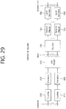
- FIG. 2 shows a radio protocol architecture of a user plane, in accordance with an embodiment of the present disclosure.
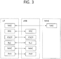
- FIG. 3 shows a radio protocol architecture of a control plane, in accordance with an embodiment of the present disclosure.
- the user plane is a protocol stack for user data transmission
- the control plane is a protocol stack for control signal transmission.
- a physical (PHY) layer belongs to the L1.
- a physical (PHY) layer provides an information transfer service to a higher layer through a physical channel.
- the PHY layer is connected to a medium access control (MAC) layer.
- Data is transferred (or transported) between the MAC layer and the PHY layer through a transport channel.
- the transport channel is sorted (or categorized) depending upon how and according to which characteristics data is being transferred through the radio interface.
- the physical channel may be modulated by using an orthogonal frequency division multiplexing (OFDM) scheme and uses time and frequency as radio resource.
- OFDM orthogonal frequency division multiplexing
- the MAC layer provides services to a radio link control (RLC) layer, which is a higher layer of the MAC layer, via a logical channel.
- RLC radio link control
- the MAC layer provides a function of mapping multiple logical channels to multiple transport channels.
- the MAC layer also provides a function of logical channel multiplexing by mapping multiple logical channels to a single transport channel.
- the MAC layer provides data transfer services over logical channels.
- the RLC layer performs concatenation, segmentation, and reassembly of Radio Link Control Service Data Unit (RLC SDU).
- RLC SDU Radio Link Control Service Data Unit
- TM transparent mode
- UM unacknowledged mode
- AM acknowledged mode
- An AM RLC provides error correction through an automatic repeat request (ARQ).
- the radio resource control (RRC) layer is defined only in a control plane. And, the RRC layer performs a function of controlling logical channel, transport channels, and physical channels in relation with configuration, re-configuration, and release of radio bearers.
- the RB refers to a logical path being provided by the first layer (PHY layer) and the second layer (MAC layer, RLC layer, Packet Data Convergence Protocol (PDCP) layer) in order to transport data between the UE and the network.
- Functions of a PDCP layer in the user plane include transfer, header compression, and ciphering of user data.
- Functions of a PDCP layer in the control plane include transfer and ciphering/integrity protection of control plane data.
- the configuration of the RB refers to a process for specifying a radio protocol layer and channel properties in order to provide a particular service and for determining respective detailed parameters and operation methods.
- the RB may then be classified into two types, i.e., a signaling radio bearer (SRB) and a data radio bearer (DRB).
- SRB is used as a path for transmitting an RRC message in the control plane
- DRB is used as a path for transmitting user data in the user plane.
- an RRC_CONNECTED state When an RRC connection is established between an RRC layer of the UE and an RRC layer of the E-UTRAN, the UE is in an RRC_CONNECTED state, and, otherwise, the UE may be in an RRC_IDLE state.
- an RRC_INACTIVE state is additionally defined, and a UE being in the RRC_INACTIVE state may maintain its connection with a core network whereas its connection with the base station is released.
- Downlink transport channels transmitting (or transporting) data from a network to a UE include a Broadcast Channel (BCH) transmitting system information and a downlink Shared Channel (SCH) transmitting other user traffic or control messages. Traffic or control messages of downlink multicast or broadcast services may be transmitted via the downlink SCH or may be transmitted via a separate downlink Multicast Channel (MCH).
- uplink transport channels transmitting (or transporting) data from a UE to a network include a Random Access Channel (RACH) transmitting initial control messages and an uplink Shared Channel (SCH) transmitting other user traffic or control messages.
- RACH Random Access Channel
- SCH uplink Shared Channel
- Logical channels existing at a higher level than the transmission channel and being mapped to the transmission channel may include a Broadcast Control Channel (BCCH), a Paging Control Channel (PCCH), a Common Control Channel (CCCH), a Multicast Control Channel (MCCH), a Multicast Traffic Channel (MTCH), and so on.
- BCCH Broadcast Control Channel
- PCCH Paging Control Channel
- CCCH Common Control Channel
- MCCH Multicast Control Channel
- MTCH Multicast Traffic Channel
- a physical channel is configured of a plurality of OFDM symbols in the time domain and a plurality of sub-carriers in the frequency domain.
- One subframe is configured of a plurality of OFDM symbols in the time domain.
- a resource block is configured of a plurality of OFDM symbols and a plurality of sub-carriers in resource allocation units. Additionally, each subframe may use specific sub-carriers of specific OFDM symbols (e.g., first OFDM symbol) of the corresponding subframe for a Physical Downlink Control Channel (PDCCH), i.e., L1/L2 control channels.
- PDCCH Physical Downlink Control Channel
- a Transmission Time Interval (TTI) refers to a unit time of a subframe transmission.
- FIG. 4 shows a structure of an NR system, in accordance with an embodiment of the present disclosure.
- a Next Generation - Radio Access Network may include a next generation-Node B (gNB) and/or eNB providing a user plane and control plane protocol termination to a user.
- FIG. 4 shows a case where the NG-RAN includes only the gNB.
- the gNB and the eNB are connected to one another via Xn interface.
- the gNB and the eNB are connected to one another via 5 th Generation (5G) Core Network (5GC) and NG interface. More specifically, the gNB and the eNB are connected to an access and mobility management function (AMF) via NG-C interface, and the gNB and the eNB are connected to a user plane function (UPF) via NG-U interface.
- AMF access and mobility management function
- UPF user plane function
- FIG. 5 shows a functional division between an NG-RAN and a 5GC, in accordance with an embodiment of the present disclosure.
- the gNB may provide functions, such as Inter Cell Radio Resource Management (RRM), Radio Bearer (RB) control, Connection Mobility Control, Radio Admission Control, Measurement Configuration & Provision, Dynamic Resource Allocation, and so on.
- RRM Inter Cell Radio Resource Management
- RB Radio Bearer
- An AMF may provide functions, such as Non Access Stratum (NAS) security, idle state mobility processing, and so on.
- a UPF may provide functions, such as Mobility Anchoring, Protocol Data Unit (PDU) processing, and so on.
- a Session Management Function (SMF) may provide functions, such as user equipment (UE) Internet Protocol (IP) address allocation, PDU session control, and so on.
- UE user equipment
- IP Internet Protocol
- FIG. 6 shows a structure of a radio frame of an NR, in accordance with an embodiment of the present disclosure.
- a radio frame may be used for performing uplink and downlink transmission.
- a radio frame has a length of 10ms and may be defined to be configured of two half-frames (HFs).
- a half-frame may include five 1ms subframes (SFs).
- a subframe (SF) may be divided into one or more slots, and the number of slots within a subframe may be determined in accordance with subcarrier spacing (SCS).
- SCS subcarrier spacing
- Each slot may include 12 or 14 OFDM(A) symbols according to a cyclic prefix (CP).
- CP cyclic prefix
- each slot may include 14 symbols.
- each slot may include 12 symbols.
- a symbol may include an OFDM symbol (or CP-OFDM symbol) and a Single Carrier-FDMA (SC-FDMA) symbol (or Discrete Fourier Transform-spread-OFDM (DFT-s-OFDM) symbol).
- Table 1 shown below represents an example of a number of symbols per slot (N slot symb ), a number slots per frame (N frame,u slot ), and a number of slots per subframe (N subframe,u slot ) in accordance with an SCS configuration (u), in a case where a normal CP is used.
- Table 2 shows an example of a number of symbols per slot, a number of slots per frame, and a number of slots per subframe in accordance with the SCS, in a case where an extended CP is used.
- OFDM(A) numerologies e.g., SCS, CP length, and so on
- a (absolute time) duration (or section) of a time resource e.g., subframe, slot or TTI
- a time unit (TU) for simplicity
- multiple numerologies or SCSs for supporting various 5G services may be supported.
- an SCS is 15kHz
- a wide area of the conventional cellular bands may be supported, and, in case an SCS is 30kHz/60kHz a dense-urban, lower latency, wider carrier bandwidth may be supported.
- the SCS is 60kHz or higher, a bandwidth that is greater than 24.25GHz may be used in order to overcome phase noise.
- An NR frequency band may be defined as two different types of frequency ranges.
- the two different types of frequency ranges may be FR1 and FR2.
- the values of the frequency ranges may be changed (or varied), and, for example, the two different types of frequency ranges may be as shown below in Table 3.
- FR1 may mean a "sub 6GHz range”
- FR2 may mean an "above 6GHz range” and may also be referred to as a millimeter wave (mmW).
- mmW millimeter wave
- FR1 may include a band within a range of 410MHz to 7125MHz. More specifically, FR1 may include a frequency band of 6GHz (or 5850, 5900, 5925 MHz, and so on) and higher. For example, a frequency band of 6GHz (or 5850, 5900, 5925 MHz, and so on) and higher being included in FR1 may include an unlicensed band. The unlicensed band may be used for various purposes, e.g., the unlicensed band for vehicle-specific communication (e.g., automated driving).
- SCS Corresponding frequency range Subcarrier Spacing
- FIG. 7 shows a structure of a slot of an NR frame, in accordance with an embodiment of the present disclosure.
- a slot includes a plurality of symbols in a time domain.
- one slot may include 14 symbols.
- one slot may include 12 symbols.
- one slot may include 7 symbols.
- one slot may include 6 symbols.
- a carrier includes a plurality of subcarriers in a frequency domain.
- a Resource Block (RB) may be defined as a plurality of consecutive subcarriers (e.g., 12 subcarriers) in the frequency domain.
- a Bandwidth Part (BWP) may be defined as a plurality of consecutive (Physical) Resource Blocks ((P)RBs) in the frequency domain, and the BWP may correspond to one numerology (e.g., SCS, CP length, and so on).
- a carrier may include a maximum of N number BWPs (e.g., 5 BWPs). Data communication may be performed via an activated BWP.
- Each element may be referred to as a Resource Element (RE) within a resource grid and one complex symbol may be mapped to each element.
- RE Resource Element
- BWP Bandwidth Part
- the Bandwidth Part may be a continuous set of physical resource blocks (PRBs) within a given numerology.
- the PRB may be selected from a continuous partial set of a common resource block (CRB) for a given numerology on a given carrier.
- CRB common resource block
- a receiving bandwidth and a transmitting bandwidth of a user equipment are not required to be as wide (or large) as the bandwidth of the cell, and the receiving bandwidth and the transmitting bandwidth of the UE may be controlled (or adjusted).
- the UE may receive information/configuration for bandwidth control (or adjustment) from a network/base station.
- the bandwidth control (or adjustment) may be performed based on the received information/configuration.
- the bandwidth control (or adjustment) may include reduction/expansion of the bandwidth, position change of the bandwidth, or change in subcarrier spacing of the bandwidth.
- the bandwidth may be reduced during a duration with little activity in order to save power.
- a position of the bandwidth may be relocated (or moved) from a frequency domain.
- the position of the bandwidth may be relocated (or moved) from a frequency domain in order to enhance scheduling flexibility.
- subcarrier spacing of the bandwidth may be changed.
- the subcarrier spacing of the bandwidth may be changed in order to authorize different services.
- a subset of a total cell bandwidth of a cell may be referred to as a Bandwidth Part (BWP).
- BA may be performed when a base station/network configures BWPs to the UE, and when the base station/network notifies the BWP that is currently in an active state, among the BWPs, to the UE.
- the BWP may be one of an active BWP, an initial BWP, and/or a default BWP.
- the UE may not monitor a downlink radio link quality in a DL BWP other than the active DL BWP within a primary cell (PCell).
- the UE may not receive a PDCCH, a PDSCH or a CSI-RS (excluding only the RRM) from outside of the active DL BWP.
- the UE may not trigger a Channel State Information (CSI) report for an inactive DL BWP.
- the UE may not transmit a PUCCH or a PUSCH from outside of an inactive DL BWP.
- CSI Channel State Information
- an initial BWP may be given as a continuous RB set for an RMSI CORESET (that is configured by a PBCH).
- an initial BWP may be given by a SIB for a random access procedure.
- a default BWP may be configured by a higher layer.
- an initial value of a default BWP may be an initial DL BWP. For energy saving, if the UE fails to detect DCI during a predetermined period of time, the UE may switch the active BWP of the UE to a default BWP.
- a BWP may be defined for the SL.
- the same SL BWP may be used for transmission and reception.
- a transmitting UE may transmit an SL channel or SL signal within a specific BWP
- a receiving UE may receive an SL channel or SL signal within the same specific BWP.
- the SL BWP may be defined separately from a Uu BWP, and the SL BWP may have a separate configuration signaling from the Uu BWP.
- the UE may receive a configuration for an SL BWP from the base station/network.
- the SL BWP may be configured (in advance) for an out-of-coverage NR V2X UE and an RRC_IDLE UE. For a UE operating in the RRC_CONNECTED mode, at least one SL BWP may be activated within a carrier.
- FIG. 8 shows an example of a BWP, in accordance with an embodiment of the present disclosure. In the embodiment of FIG. 8 , it is assumed that three BWPs exist.
- a common resource block may be a carrier resource block that is numerated from one end of a carrier band to another end.
- a PRB may be a resource block that is numerated within each BWP.
- Point A may indicate a common reference point for a resource block grid.
- a BWP may be configured by Point A, an offset (N start BWP ) from Point A, and a bandwidth (N size BWP ).
- Point A may be an external reference point of a PRB of a carrier having subcarrier 0 of all numerologies (e.g., all numerologies being supported by the network within the corresponding carrier) aligned therein.
- the offset may be a PRB distance between a lowest subcarrier within a given numerology and Point A.
- the bandwidth may be a number of PRBs within the given numerology.
- V2X or SL communication will be described.
- FIG. 9 shows a protocol stack for a SL communication, in accordance with an embodiment of the present disclosure. More specifically, (a) of FIG. 9 shows a user plane protocol stack of LTE, and (b) of FIG. 9 shows a control plane protocol stack of LTE.
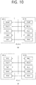
- FIG. 10 shows a protocol stack for a SL communication, in accordance with an embodiment of the present disclosure. More specifically, (a) of FIG. 10 shows a user plane protocol stack of NR, and (b) of FIG. 10 shows a control plane protocol stack of NR.
- SL Synchronization Signal SLSS
- synchronization information SLSS and synchronization information
- SLSS is a SL specific sequence, which may include a Primary Sidelink Synchronization Signal (PSSS) and a Secondary Sidelink Synchronization Signal (SSSS).
- PSSS Primary Sidelink Synchronization Signal
- SSSS Secondary Sidelink Synchronization Signal
- S-PSS Sidelink Primary Synchronization Signal
- S-SSS Sidelink Secondary Synchronization Signal
- a Physical Sidelink Broadcast Channel may be a (broadcast) channel through which basic (system) information that should first be known by the user equipment (UE) before transmitting and receiving SL signals.
- the basic information may be information related to SLSS, a Duplex mode (DM), Time Division Duplex Uplink/Downlink (TDD UL/DL) configuration, information related to a resource pool, application types related to SLSS, a subframe offset, broadcast information, and so on.
- the S-PSS, the S-SSS, and the PSBCH may be included in a block format (e.g., a SL SS/PSBCH block, hereinafter referred to as Sidelink - Synchronization Signal Block (S-SSB)).
- S-SSB may have the same numerology (i.e., SCS and CP length) as a Physical Sidelink Control Channel (PSCCH)/Physical Sidelink Shared Channel (PSSCH) within the carrier, and a transmission bandwidth may exist within a (pre-)configured SL Bandwidth Part (BWP).
- BWP SL Bandwidth Part
- a frequency position of the S-SSB may be (pre-)configured. Therefore, the UE is not required to perform a hypothesis detection in order to discover the S-SSB in the carrier.
- Each SLSS may have a physical layer SL synchronization identity (ID), and the respective value may be equal to any one value ranging from 0 to 335.
- ID physical layer SL synchronization identity
- a synchronization source may also be identified.
- values of 0, 168, 169 may indicate global navigation satellite systems (GNSS)
- values from 1 to 167 may indicate base stations
- values from 170 to 335 may indicate that the source is outside of the coverage.
- values 0 to 167 may be values being used by a network
- values from 168 to 335 may be values being used outside of the network coverage.
- FIG. 11 shows a UE performing V2X or SL communication, in accordance with an embodiment of the present disclosure.
- the term terminal may mainly refer to a terminal (or equipment) used by a user.
- a network equipment such as a base station
- the base station may also be viewed as a type of user equipment (or terminal).
- User equipment 1 may select a resource unit corresponding to a specific resource within a resource pool, which refers to a set of resources, and UE1 may then be operated so as to transmit a SL signal by using the corresponding resource unit.
- User equipment 2 which is to a receiving UE, may be configured with a resource pool to which UE1 can transmit signals, and may then detect signals of UE1 from the corresponding resource pool.
- the base station may notify the resource pool.
- another UE may notify the resource pool or a pre-determined resource may be used.
- a resource pool may be configured in a plurality of resource units, and each UE may select one resource unit or a plurality of resource units and may use the selected resource unit(s) for its SL signal transmission.
- FIG. 12 shows a resource unit for V2X or SL communication, in accordance with an embodiment of the present disclosure.
- the total frequency resources of the resource pool may be divided into N F number of resource units, the total time resources of the resource pool may be divided into N T number of resource units. Therefore, a total of N F ⁇ N T number of resource units may be defined in the resource pool.
- FIG. 12 shows an example of a case where the corresponding resource pool is repeated at a cycle of N T number of subframes.
- one resource unit (e.g., Unit #0) may be periodically and repeatedly indicated.
- an index of a physical resource unit to which a logical resource unit is mapped may be changed to a pre-determined pattern in accordance with time.
- the resource pool may refer to a set of resource units that can be used for a transmission that is performed by a user equipment (UE), which intends to transmit SL signals.
- UE user equipment
- the resource pool may be segmented to multiple types. For example, depending upon the content of a SL signal being transmitted from each resource pool, the resource pool may be divided as described below.
- SA Scheduling Assignment
- MCS Modulation and Coding Scheme
- MIMO Multiple Input Multiple Output
- TA Timing Advance
- the SA may also be multiplexed with SL data within the same resource unit and may then be transmitted, and, in this case, an SA resource pool may refer to a resource pool in which the SA is multiplexed with the SL data and then transmitted.
- the SA may also be referred to as a SL control channel.
- a Physical Sidelink Shared Channel may be a resource pool that is used by a transmitting UE for transmitting user data. If the SA is multiplexed with SL data within the same resource unit and then transmitted, only a SL data channel excluding the SA information may be transmitted from the resource pool that is configured for the SL data channel. In other words, REs that were used for transmitting SA information within a separate resource unit of the SA resource pool may still be used for transmitting SL data from the resource pool of a SL data channel.
- a discovery channel may be a resource pool that is used by the transmitting UE for transmitting information, such as its own ID. By doing so, the transmitting UE may allow a neighboring UE to discover the transmitting UE.
- the resource pool may be identified as a different resource pool depending upon a transmission timing decision method (e.g., whether the transmission is performed at a reception point of the synchronization reference signal or whether transmission is performed at the reception point by applying a consistent timing advance), a resource allocation method (e.g., whether the base station designates a transmission resource of a separate signal to a separate transmitting UE or whether a separate transmitting UE selects a separate signal transmission resource on its own from the resource pool), and a signal format (e.g., a number of symbols occupied by each SL signal within a subframe or a number of subframes being used for the transmission of one SL signal) of the SL signal, signal intensity from the base station, a transmitting power intensity (or level) of a SL UE, and so
- a transmission timing decision method e.g., whether the transmission is performed at a reception point of the synchronization reference signal or whether transmission is performed at the reception point by applying a consistent timing advance
- a resource allocation method
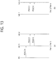
- FIG. 13 shows procedures of a UE performing V2X or SL communication according to a transmission mode (TM), in accordance with an embodiment of the present disclosure. Specifically, (a) of FIG. 13 shows a UE operation related to a transmission mode 1 or a transmission mode 3, and (b) of FIG. 13 shows a UE operation related to a transmission mode 2 or a transmission mode 4.
- the base station performs resource scheduling to UE1 via PDCCH (more specifically, Downlink Control Information (DCI)), and UE1 performs SL/V2X communication with UE2 according to the corresponding resource scheduling.
- DCI Downlink Control Information
- UE1 After transmitting sidelink control information (SCI) to UE2 via physical sidelink control channel (PSCCH), UE1 may transmit data based on the SCI via physical sidelink shared channel (PSSCH).
- SCI sidelink control information
- PSSCH physical sidelink shared channel
- transmission mode 1 may be applied to a general SL communication
- transmission mode 3 may be applied to a V2X SL communication.
- transmission modes 2/4 the UE may schedule resources on its own. More specifically, in case of LTE SL, transmission mode 2 may be applied to a general SL communication, and the UE may select a resource from a predetermined resource pool on its own and may then perform SL operations. Transmission mode 4 may be applied to a V2X SL communication, and the UE may carry out a sensing/SA decoding procedure, and so on, and select a resource within a selection window on its own and may then perform V2X SL operations. After transmitting the SCI to UE2 via PSCCH, UE1 may transmit SCI-based data via PSSCH.
- the transmission mode may be abbreviated to the term mode.
- SL resource allocation modes may be defined.
- the base station may schedule SL resources that are to be used for SL transmission.
- the user equipment UE
- the user equipment may determine a SL transmission resource from SL resources that are configured by the base station/network or predetermined SL resources.
- the configured SL resources or the pre-determined SL resources may be a resource pool.
- the UE may autonomously select a SL resource for transmission.
- the UE may assist (or help) SL resource selection of another UE.
- the UE may be configured with an NR configured grant for SL transmission.
- the UE may schedule SL transmission of another UE.
- mode 2 may at least support reservation of SL resources for blind retransmission.
- the sensing procedure may be defined as a process decoding the SCI from another UE and/or SL measurement.
- the decoding of the SCI in the sensing procedure may at least provide information on a SL resource that is being indicated by a UE transmitting the SCI.
- the sensing procedure may use L1 SL Reference Signal Received Power (RSRP) measurement, which is based on SL Demodulation Reference Signal (DMRS).
- RSRP SL Reference Signal Received Power
- DMRS SL Demodulation Reference Signal
- the resource (re-)selection procedure may use a result of the sensing procedure in order to determine the resource for the SL transmission.
- FIG. 14 shows a method of selecting a transmission resource by a UE, in accordance with an embodiment of the present disclosure.
- the UE may identify transmission resources reserved by another UE or resources being used by another UE via sensing within a sensing window, and, after excluding the identified resources from a selection window, the UE may randomly select a resource from resources having low interference among the remaining resources.
- the UE may decode the PSCCH including information on the cycles of the reserved resources, and, then, the UE may measure a PSSCH RSRP from resources that are periodically determined based on the PSCCH. The UE may exclude resources having the PSSCH RSRP that exceeds a threshold value from the selection window. Thereafter, the UE may randomly select a SL resource from the remaining resources within the selection window.
- the UE may measure a Received Signal Strength Indicator (RSSI) of the periodic resources within the sensing window and may then determine the resources having low interference (e.g., the lower 20% of the resources). Additionally, the UE may also randomly select a SL resource from the resources included in the selection window among the periodic resources. For example, in case the UE fails to perform decoding of the PSCCH, the UE may use the above described methods.
- RSSI Received Signal Strength Indicator
- FIG. 15 shows three different cast types, in accordance with an embodiment of the present disclosure.
- FIG. 15 shows a broadcast type SL communication
- (b) of FIG. 15 shows a unicast type SL communication
- (c) of FIG. 15 shows a groupcast type SL communication.
- the UE may perform one-to-one communication with another UE.
- the UE may perform SL communication with one or more other UEs within the group to which the corresponding UE belongs.
- the SL groupcast communication may be replaced with SL multicast communication, SL one-to-many communication, and so on.
- HARQ Hybrid Automatic Repeat Request
- HARQ feedback and HARQ combining in a physical layer may be supported.
- a receiving UE operates in a Resource Allocation Mode 1 or 2
- the receiving UE may receive a PSSCH from a transmitting UE, and the receiving UE may transmit an HARQ feedback corresponding to the PSSCH to the transmitting UE by using a Sidelink Feedback Control Information (SFCI) format via Physical Sidelink Feedback Channel (PSFCH).
- SFCI Sidelink Feedback Control Information
- PSFCH Physical Sidelink Feedback Channel
- an SL HARQ feedback may be enabled for the unicast.
- the receiving UE may decode a PSCCH targeting the receiving UE, and, when the receiving UE successfully decodes a transport block related to the PSCCH, the receiving UE may generate an HARQ-ACK. Thereafter, the receiving UE may transmit the HARQ-ACK to the transmitting UE.
- the receiving UE may generate an HARQ-NACK, and the receiving UE may transmit the HARQ-NACK to the transmitting UE.
- an SL HARQ feedback may be enabled for the groupcast.
- two different types of HARQ feedback options may be supported for the groupcast.
- HARQ feedback may be supported in unicast and groupcast communication.
- a transmitting UE may establish link association with multiple receiving UEs.
- TX UE transmitting UE
- RX UEs receiving UEs
- this may be referred to as a connection-oriented groupcast.
- a transmitting UE may not establish link association with multiple receiving UEs, the transmitting UE may perform SL communication with the multiple receiving UEs by using a broadcast method.
- a receiving UE may determine whether or not to perform HARQ feedback based on a communication distance or absolute distance, and so on, for all broadcast transmissions.
- a transmitting UE performs sidelink communication with one or more UEs within a group without any RRC connection on a PC5 interface, this may be referred to as a connection-less groupcast.
- a transmitting UE may transmit information on its communication distance or information on a target distance of a service being transmitted by the transmitting UE to multiple receiving UEs. Additionally, the transmitting UE may transmit information on its location to multiple receiving UEs. In this case, the multiple receiving UEs may determine their distances with the transmitting UE based on the received information, and the multiple receiving UEs may determine whether or not to perform HARQ feedback to the transmitting UE. A receiving UE may not transmit unnecessary HARQ feedback by performing the distance-based HARQ feedback operation, and, accordingly, resource availability may be enhanced. Additionally, decoding efficiency resulting from re-transmission of the transmitting UE may be enhanced.
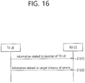
- FIG. 16 shows a procedure for transmitting, by a transmitting UE, information associated to its location, in accordance with an embodiment of the present disclosure.
- the embodiment of FIG. 16 may be combined with various embodiments of the present disclosure.
- the order of each process step may be changed.
- a transmitting UE may transmit information related to a location of the transmitting UE to another UE (e.g., receiving UE).
- another UE e.g., receiving UE
- information related to the location of the transmitting UE may be transmitted to another UE through part of a channel being pre-defined in advance for the transmitting UE.
- the information related to the location of the transmitting UE may be included in a Sidelink Control Information (SCI) being transmitted by the transmitting UE and may, then, be transmitted to another UE.
- SCI Sidelink Control Information
- the information related to the location of the transmitting UE may be included in part of a V2X-related message and may, then, be transmitted to another UE.
- the information related to the location of the transmitting UE may be piggy-backed to part of a V2X-related message and may, then, be transmitted to another UE.
- the information related to the location of the transmitting UE may be piggy-backed to a data region and may, then, be transmitted to another UE.
- the information related to the location of the transmitting UE may be transmitted to another UE through a PSSCH.
- information related to the location of the transmitting UE being transmitted on a SCI and information related to the located of the transmitting UE being piggy-backed to a data region and then transmitted may be information having a hierarchical relation.
- the information related to the location of the transmitting UE being transmitted on a SCI by the transmitting UE may be information being divided (or split) to a high granularity.
- the information related to the located of the transmitting UE being piggy-backed to a data region and then transmitted by the transmitting UE may be information having finer granularity.
- the transmitting UE may transmit a target distance to another UE (e.g., receiving UE) according to a service being transmitted by the transmitting UE.
- the transmitting UE may transmit a target distance related to a service being transmitted by the transmitting UE to another UE.
- the transmitting UE may transmit a target distance being mapped to a service being transmitted by the transmitting UE to another UE.
- the target distance related to a service being transmitted by the transmitting UE may be transmitted through a channel being pre-defined in advance for the transmitting UE.
- the target distance related to a service being transmitted by the transmitting UE may be included in a Sidelink Control Information (SCI) being transmitted by the transmitting UE and may, then, be transmitted to another UE.
- SCI Sidelink Control Information
- the target distance related to a service being transmitted by the transmitting UE may be included in part of a V2X-related message and may, then, be transmitted to another UE.
- the target distance related to a service being transmitted by the transmitting UE may be piggy-backed to part of a V2X-related message and may, then, be transmitted to another UE.
- the target distance related to a service being transmitted by the transmitting UE may be piggy-backed to a data region and may, then, be transmitted to another UE.
- the target distance related to a service being transmitted by the transmitting UE may be transmitted to another UE through a PSSCH.
- a transmitting UE may transmit its geographical location information to another UE (e.g., receiving UE).
- the geographical location information may include at least one of longitude, latitude, and/or altitude.
- the transmitting UE may acquire or determine its geographical location information.
- the transmitting UE may acquire or determine its geographical location information.
- GPS Global Positioning System
- geographical location information included in the CAM message may be a coordinates system referred to as WGS84 (longitude-latitude).
- WGS84 coordinates system locations of X(latitude), Y(longitude), Z(altitude) may be expressed in degrees, minutes, and seconds.
- the WGS84 coordinates system may be converted to integers so that the location can be expressed to up to 0.1 micro degree (e.g., approximately 1cm), and this means that each of X, Y, Z configures a data size of approximately 10 bits.
- the transmitting UE expresses all of the absolute locations X, Y, Z by using the location information within the CAM message, and in case the transmitting UE transmits all of the absolute locations to another UE, the size of a data payload being transmitted by the transmitting UE from a physical layer may be excessively increased.
- the transmitting UE may reduce the information on X, Y, Z and transmit the reduced information to another UE.
- the transmitting UE may not transmit all of the information related to the absolute location to another UE.
- the transmitting UE may only transmit part of the information, among all of the information related to the absolute location.
- the transmitting UE may signal the information corresponding to part of the region by performing masking. The reason why this method can be used is because the integer-converted information is location information having absolute coordinates, wherein part of the region has a high-granularity distance.
- a location of the transmitting UE according to the longitude-latitude coordinates system is 36 degrees 10 minutes 10 seconds.
- a difference of 1 degree between 36 degrees and 37 degrees may mean a distance difference of approximately 111km.
- the transmitting UE may exclude the information corresponding to 36 degrees from the information related to its location, and may transmit the processed information to another UE (e.g., receiving UE).
- the receiving UE may assume that its location, which is known from the GPS information, is in the same 36 degrees as the transmitting UE.
- the receiving UE existing at a location corresponding to 36 degrees may determine that the transmitting UE also exists at a location corresponding to 36 degrees.
- the receiving UE may restrict information indicating low granularity, among the information related to its location. For example, the transmitting UE may exclude information corresponding to 10 seconds from the information related to its location and may then transmit the processed information to another UE (e.g., receiving UE).
- another UE e.g., receiving UE
- the transmitting UE may restrict the information by adequately masking the information related to its location, data size of the information related to the location of the transmitting UE being transmitted by the transmitting UE may be reduced.
- the transmitting UE may mask or restrict the information related to the location of the transmitting UE.
- the transmitting UE may mask or restrict the information related to the location of the transmitting UE.
- regulations on how the transmitting UE is to perform masking on the information related to its location may be pre-determined in advance by a higher layer, and such regulations may be transmitted to the transmitting UE from the higher layer.
- regulations on how the transmitting UE is to perform masking on the information related to its location may be pre-determined in advance by a higher layer, and such regulations may be periodically transmitted or updated, in long term, to the transmitting UE from the higher layer.
- the transmitting UE may determine how to perform masking on the information related to the transmitting UE.
- regulations on which information shall be excluded from the information related to its location and transmitting the processed information to the receiving UE may be pre-determined in advance by a higher layer, and such regulations may be transmitted to the transmitting UE from the higher layer.
- regulations on which information shall be excluded from the information related to its location and transmitting the processed information to the receiving UE may be pre-determined in advance by a higher layer, and such regulations may be periodically transmitted or updated, in long term, to the transmitting UE from the higher layer.
- the transmitting UE may determine which information shall be excluded from the information related to its location and, then, to transmit the processed information to the receiving UE.
- the transmitting UE may not need to accurately deliver its absolute location to another UE.
- the transmitting UE may reduce the information related to its location and may transmit the reduced information to another UE, so that a target distance of a service being transmitted by the transmitting UE or an extent of a wireless communication distance can be expressed.
- a target distance of a service being transmitted by the transmitting UE or an extent of a wireless communication distance can be expressed.
- the transmitting UE is currently located on an X coordinate, and that the location of the X coordinate is expressed in the form of an integer, such as "123456".
- each index may indicate an extent (or approximation) in meters of an actual distance.
- information on "12" may express an extent in units of several hundreds of kilometers (km).
- the transmitting UE may restrict the corresponding information from the location information that is to be transmitted.
- "56" may express several meter units, and, in this case, the transmitting UE may not need to transmit such fine distance information, as described above. More specifically, for example, among the information related to its location, the transmitting UE may roughly transmit part of the information. For example, in “123456", the transmitting UE may transmit only the information on "34" to another UE. After receiving the information on "34", the receiving UE may know high-granularity location information through its GPS information, and the receiving UE may calculate its distance from the transmitting UE by using its location information and the information on "34". Thereafter, the receiving UE may compare a target distance related to a service that is received from the transmitting UE with the calculated distance between the transmitting UE and the receiving UE and may, then, determine whether or not to perform HARQ feedback for the service.
- FIG. 17 shows a method for determining, by a receiving UE, whether or not to perform HARQ feedback based on its distance from a transmitting UE, in accordance with an embodiment of the present disclosure.
- a transmitting UE may restrict part of the information and transmit the restricted location information to a receiving UE, and, then, the transmitting UE may transmit a target distance related to a service to the receiving UE.
- the receiving UE may calculate a distance between the receiving UE and the transmitting UE. If the distance between the receiving UE and the transmitting UE is shorter than the target distance related to a service, the receiving UE may transmit HARQ feedback on the service to the transmitting UE. If the distance between the receiving UE and the transmitting UE is longer than the target distance related to a service, the receiving UE may not transmit HARQ feedback on the service to the transmitting UE.
- the receiving UE may manage information by processing the restricted location information of the transmitting UE. For example, the receiving UE may apply ⁇ 1 to/from a Most Significant Bit (MSB) among the restricted location information of the transmitting UE, which is received from the transmitted UE. Subsequently, the receiving UE may determine all candidate groups applying ⁇ 1 to/from the MSB as the location information of the transmitting UE.
- MSB Most Significant Bit
- the receiving UE may calculate a distance between the receiving UE and the transmitting UE for all candidate groups, and, then, among all candidate groups, the receiving UE may determine that the transmitting UE exists in a distance having the smallest value.
- a masking process cutting the MSB is performed so that the MSB can be cut in communication range units, it may be determined that one transmitting UE exists in one communication range.
- the transmitting UE may transmit restricted location information to the receiving UE.
- the restricted information may be "34".
- the receiving UE may apply ⁇ 1 to/from the MSB, and, then, the receiving UE may determine that the location of the transmitting UE is one of "24", "34", or "44".
- the receiving UE may calculate its distance from the transmitting UE by using its location information and the information processed by the receiving UE.
- the distance between the receiving UE and the transmitting UE, which is calculated by the receiving UE may be A, B, and C. If A > B > C, the receiving UE may determine that its distance from the transmitting UE is C. Thereafter, the receiving UE may compare a target distance related to a service that is transmitted by the transmitting UE to C and may then determine whether or not to transmit a HARQ feedback to the transmitting UE.
- a ZONE ID may mean a ZONE index using the geographical information of a UE, which is defined in a V2X system of 3GPP Release 14.
- a split granularity of a ZONE may be differently configured in accordance with a service type or service requirements (e.g., priority level information, reliability, latency) and/or speed of a UE, and so on.
- split granularity of a ZONE may be signaled in advance to the UE from a higher layer.
- the transmitting UE may deliver its location to another UE based on a ZONE ID to which the transmitting UE belongs.
- the transmitting UE delivers a ZONE ID, which is defined in a V2X system of a legacy 3GPP Release 14, to another UE, the following problems may occur.
- the transmitting UE may deliver a ZONE ID of a region to which it belongs to another UE, and, accordingly, if the receiving UE performs HARQ feedback based on the ZONE ID, problems may occur, as shown in FIG. 18 .
- FIG. 18 is a diagram for describing problems that may occur in case a receiving UE performs HARQ feedback based on a ZONE ID transmitted from a transmitting UE.
- a target distance of a service being transmitted by UE1 may be shorter than a distance between UE1 and a UE (e.g., UE3) within the same ZONE.
- a target distance of a service being transmitted by UE1 may be longer than a distance between UE1 and a UE (e.g., UE2) belonging to a different ZONE.
- HARQ feedback may not be needed between UE1 and UE3 belonging to the same ZONE. Additionally, due to the target distance of a service, HARQ feedback may be needed between UE1 and UE2, which belongs to a different ZONE. However, according to a ZONE ID based HARQ feedback, UE3 transmits HARQ feedback on the information, which is received from UE1, to UE1, and UE2 does not transmit HARQ feedback on the information, which is received from UE1, to UE1.
- a problem may occur, wherein HARQ feedback cannot be performed between UEs belonging to a close-ranged inter-ZONE.
- the transmitting UE delivers information related to its location based on a ZONE ID, the above-described problem cannot be resolved.
- the transmitting UE may signal or transmit a ZONE ID of a zone (or region) to which it belongs and a ZONE ID of a zone (or region), which is adjacent to the zone (or region) to which the transmitting UE belongs, together to a receiving UE. Accordingly, the receiving UE, which has received the ZONE ID of the zone being adjacent to the zone to which the transmitting UE belongs, may determine whether or not to perform HARQ feedback. Thereafter, the receiving UE may transmit a HARQ ACK or a HARQ NACK to the transmitting UE.
- the receiving UE may transmit the ZONE ID of the zone to which the receiving UE belongs and the HARQ ACK or HARQ NACK together to the transmitting UE.
- the receiving UE may notify the location of the zone to which it belongs to the transmitting UE.
- the transmitting UE may perform beamforming (e.g., analog beamforming) towards a direction of the corresponding zone based on the ZONE ID of the zone to which the receiving UE belongs. More specifically, the transmitting UE may perform efficient re-transmission based on the ZONE ID of the zone to which the receiving UE belongs.
- the operation of determining, by the receiving UE, whether or not to perform HARQ feedback based on the ZONE ID may be as described below. For example, if the ZONE ID of the zone to which the receiving UE belongs is included in the ZONE ID that is received from the transmitting UE, and if a distance between the receiving UE and the transmitting UE is included in the target distance related to a service being transmitted by the transmitting UE, the receiving UE may transmit a HARQ ACK or a HARQ NACK corresponding to the service to the transmitting UE.
- the transmitting UE when the transmitting UE transmits the ZONE ID of the zone to which it belongs and the ZONE ID of a zone being adjacent to the zone to which the transmitting UE belongs, if the signaling overhead is too large, the transmitting UE may signal or transmit only part of the ZONE IDs to the receiving UE.
- FIG. 19 shows a method for transmitting, by a transmitting UE, only part of ZONE IDs to a receiving UE, in accordance with an embodiment of the present disclosure.
- UE1 may signal or transmit a ZONE ID of a zone to which UE1 belongs and ZONE IDs of zones corresponding to an upper side, a lower side, a left side, and a right side of the zone to which UE1 belongs.
- UE1 may signal or transmit a ZONE ID of Zone b, a ZONE ID of Zone d, a ZONE ID of Zone e, a ZONE ID of Zone f, and a ZONE ID of Zone h.
- UE2 may transmit a HARQ ACK or HARQ NACK for the service to UE1.
- UE3 may transmit a HARQ ACK or HARQ NACK for the service to UE1.
- the transmitting UE may transmit only the ZONE IDs of part of the zones. For example, the transmitting UE may transmit only part of a Least Significant Bit (LSB) of the ZONE IDs.
- LSB Least Significant Bit
- the HARQ operation may not be performed between UEs located in diagonal ZONEs.
- the transmitting UE may transmit a ZONE ID of the zone to which the transmitting UE belongs and ZONE IDs of zones neighboring the zone to which the transmitting UE belongs.
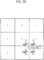
- FIG. 20 shows a method for transmitting, by a transmitting UE, all ZONE IDs to a receiving UE, in accordance with an embodiment of the present disclosure.
- the transmitting UE may transmit a ZONE ID of a zone to which the transmitting UE belongs and ZONE IDs corresponding to all zones neighboring the zone to which the transmitting UE belongs.
- UE1 may transmit a ZONE ID of Zone a, a ZONE ID of Zone b, a ZONE ID of Zone c, a ZONE ID of Zone d, a ZONE ID of Zone e, a ZONE ID of Zone f, a ZONE ID of Zone g, a ZONE ID of Zone h, and a ZONE ID of Zone i.
- the receiving UE may determine whether or not to perform HARQ feedback by using its location and a parameter (e.g., target distance, ZONE IDs of all directions) being transmitted by the transmitting UE, and the receiving UE may transmit a HARQ ACK or HARQ NACK for the service, which is transmitted from the transmitting UE, to the transmitting UE.
- a parameter e.g., target distance, ZONE IDs of all directions
- the transmitting UE may restrict transmission to part of the zones of the ZONE IDs.
- the transmitting UE may configure or determine sub-ZONEs.
- FIG. 21 shows a method for transmitting, by a transmitting UE, sub-ZONE IDs to a receiving UE, in accordance with an embodiment of the present disclosure.
- the ZONE may be granulated and sub-divided.
- the granulated and sub-divided ZONE may be referred to as sub-ZONEs.
- the transmitting UE may configure a new grid based on the sub-divided sub-ZONEs, and the transmitting UE may transmit an ID of a sub-ZONE to which it belongs and IDs of sub-ZONES that are adjacent to the sub-ZONE to which the transmitting UE belongs to other UE.
- the transmitting UE may restrict transmission to part of the zones of the sub-ZONE IDs.
- the receiving UE may determine whether or not to transmit HARQ feedback for the service based on an absolute distance between the transmitting UE and the receiving UE and the target distance of the service being transmitted by the transmitting UE.
- the receiving UE may enhance accuracy in determining whether or not to transmit the HARQ feedback by using a metric (e.g., RSRP) indicating a radio distance.
- a metric e.g., RSRP
- the HARQ feedback may include a HARQ ACK or a HARQ NACK.
- the receiving UE may determine whether or not to transmit HARQ feedback based on rough distance information (e.g., rough distance information between the receiving UE and the transmitting UE) acquired from the restricted location information transmitted from the transmitting UE and a RSRP measurement result corresponding to a message received from the transmitting UE.
- the receiving UE may measure a RSRP corresponding to a message received from the transmitting UE, and, in case the RSRP is greater than a specific threshold value, the receiving UE may transmit a HARQ ACK or a HARQ NACK.
- the transmitting UE may transmit information related to its location by combining at least one of Proposed Method #1 to Proposed Method #3.
- the transmitting UE may combine information, which uses an absolute location of Proposed Method #1, and ZONE IDs of Proposed Method #2 and Proposed Method #3 and may then transmit the combined information. More specifically, for example, if the transmitting UE adds bits that roughly indicate its absolute location by using additional bits of the ZONE IDs and transmits the added bits to the receiving UE, the receiving UE may roughly determine in which location within the ZONE the transmitting UE exists.
- the receiving UE may determine a rough location of the transmitting UE. Additionally, the receiving UE may know the target distance of a service being transmitted by the transmitting UE and may determine whether or not to perform HARQ feedback. However, since the location information of the transmitting UE, which is transmitted by the transmitting UE, is not an accurate information, for example, in a ZONE boundary or in a high granularity (e.g., 100km) boundary of the location information, the receiving UE may be incapable of locating the location of the transmitting UE due to the restricted information.
- FIG. 22 is a diagram for describing a problem where a receiving UE is incapable of locating a location of a transmitting UE due to restricted information.
- the transmitting UE transmits only latitude information among the absolute location information.
- a difference of 1 degree may indicate a distance granularity of approximately 111km.
- the receiving UE receiving restricted location information from the transmitting UE and if the receiving UE determines a location of the transmitting UE by using the restricted information from which large-scaled information is unavailable, a problem may occur in that the receiving UE may perform wrong measurement of the location of the transmitting UE.
- the transmitting UE may signal or transmit, to the receiving UE, information on an offset size of its location in a large scale from the receiving UE through a pre-defined channel.
- the pre-defined channel may include a PSSCH and/or a PSCCH.
- the transmitting UE may transmit or signal, to the receiving UE, that the transmitting UE has an offset of +1 degree from the receiving UE.
- the transmitting UE may transmit location information to the receiving UE through a data channel (e.g., PSSCH).
- the location information may be additional location information.
- the additional location information may be the remaining detailed location information that was restricted for providing the rough location information.
- the receiving UE may determine whether or not to decode a PSSCH by using the rough location information or destination ID of the transmitting UE that is transmitted by the transmitting UE on the PSCCH.
- the receiving UE may determine whether or not to transmit HARQ-ACK feedback corresponding to the PSSCH based on more accurate location information of the transmitting UE, which is transmitted by the transmitting UE on the PSSCH. For example, until the receiving UE performs successful decoding of the PSSCH being transmitted by the transmitting UE, the receiving UE may determine whether or not to transmit HARQ-ACK feedback based on rough location information of the transmitting UE, which is transmitted by the transmitting UE on the PSSCH.
- the transmitting UE may transmit additional transmitting UE (TX UE) location information just as PUSCH UCI piggy-back and may perform decoupling of a success or failure in decoding data and a success or failure in decoding additional TX UE location information.
- TX UE transmitting UE
- the additional TX UE location information may be referred to as ADD_LOINFO.
- UCI decoding may be independently performed by using channel coding decoupling, and so on, a success or failure in decoding data and a success or failure in decoding additional TX UE location information may be decoupled in the receiving UE.
- the above-described proposed method may be effective in Groupcast Option 1.
- the above-described proposed method may be advantageous when a NACK only feedback method, which enhances feedback resource efficiency in groupcast communication.
- the receiving UE may finally determine whether or not to transmit HARQ NACK based on (relatively) accurate location information of the transmitting UE, which is derived by using the ADD_LOINFO.
- the receiving UE may determine whether or not to perform decoding of the ADD_LOINFO and data based on rough location information and/or destination ID, and so on, of the transmitting UE on the PSCCH.
- the receiving UE may, similarly, transmit HARQ NACK to the transmitting UE by using only the information on the PSCCH. For example, if the receiving UE successfully decodes the data, regardless of the success or failure in decoding the ADD_LOINFO, the receiving UE may not transmit the HARQ feedback.
- the receiving UE may skip the decoding of the data. More specifically, the receiving UE may not perform decoding on the data.
- a Code Block Group (CBG) based re-transmission operation may be supported.
- the transmitting UE may transmit the ADD_LOINFO or location information of the transmitting UE to a specific CBG that is pre-defined in advance. Accordingly, after the receiving UE performs decoding on a specific CBG in which the location information of the transmitting UE is included, the receiving UE may determine whether or not to perform HARQ feedback on the remaining CBGs.
- the receiving UE may not perform HARQ feedback on the remaining CBGs, or the receiving UE do not attempt to perform decoding on the remaining CBGs.
- a number of a specific CBG in which the location information of the transmitting UE is included may be regulated or configured in advance, and the number of the specific CBG may be signaled to the UE.
- the transmitting UE may transmit its location information to the receiving UE.
- the transmitting UE may transmit absolute coordinates to the receiving UE, and the transmitting UE may transmit other information related to its location to the receiving UE.
- the transmitting UE may transmit optimized information for reducing the data size that is to be transmitted or transmit refined information for notifying a rough location.
- the determination method of the receiving UE may vary according to the type of information that is transmitted from the transmitting UE. More specifically, the operations of the receiving UE may vary (or may be changed).
- the transmitting UE may transmit location information of the transmitting UE to the receiving UE according to various embodiments of the present disclosure, and the location information of the transmitting UE may also be used for other operations of the receiving UE instead of the HARQ operation.
- FIG. 23 shows a procedure for receiving, by a transmitting UE performing groupcast communication, HARQ feedback from one or more receiving UEs, in accordance with an embodiment of the present disclosure.
- FIG. 24 shows an example of transmitting, by a transmitting UE, SL information having a specific target distance to one or more receiving UEs, in accordance with an embodiment of the present disclosure.
- locations of the transmitting UE and the one or more receiving UEs are the same as FIG. 24 .
- a target distance of a first SL information is the same as FIG. 24 .
- a transmitting UE may transmit a PSCCH to one or more receiving UEs.
- the transmitting UE may perform groupcast communication with one or more receiving UEs.
- one or more receiving UEs may include a first receiving UE, a second receiving UE, a third receiving UE, and a fourth receiving UE.
- the transmitting UE may transmit a PSSCH to one or more receiving UEs.
- PSSCH may be scheduled by PSCCH.
- PSSCH may be scheduled by a SCI that is transmitted through PSCCH.
- the transmitting UE may transmit location information of the transmitting UE to one or more receiving UEs through the PSSCH.
- the location information of the transmitting UE may be piggy-backed on the PSSCH and may then be transmitted to the receiving UE(s).
- the location information of the transmitting UE may be configured according to various embodiments of the present disclosure.
- the transmitting UE may transmit a first SL information to one or more receiving UEs. Additionally, the transmitting UE may transmit a target distance of the first SL information to one or more receiving UEs.
- a target distance of the first SL information may be a communication range in which the first SL information shall be transmitted.
- a target distance of the first SL information may be transmitted through a PSCCH that is related to the PSSCH.
- a target distance of the first SL information may be transmitted through the PSSCH.
- one or more receiving UEs may determine whether or not to perform HARQ feedback on the first SL information. For example, the one or more receiving UEs may calculate or acquire its distance from the transmitting UE based on location information of the transmitting UE. Additionally, the one or more receiving UEs may determine whether or not to perform HARQ feedback on the first SL information based on its distance from the transmitting UE. For example, the one or more receiving UEs may perform Groupcast Option 1 based HARQ feedback transmission.
- a distance between a first receiving UE and a transmitting UE is shorter than or equal to a target distance of the first SL information, and that the first receiving UE successfully receives the first SL information.
- the first receiving UE may not transmit HARQ ACK to the transmitting UE.
- the second receiving UE may transmit HARQ NACK to the transmitting UE.
- a distance between a third receiving UE and a transmitting UE is shorter than or equal to a target distance of the first SL information, and that the third receiving UE fails to receive the first SL information.
- the third receiving UE may transmit HARQ NACK to the transmitting UE.
- a distance between a fourth receiving UE and a transmitting UE exceeds a target distance of the first SL information.
- the fourth receiving UE may not transmit HARQ feedback to the transmitting UE.
- FIG. 25 shows a method for receiving, by a first device (100), location information of a second device (200), in accordance with an embodiment of the present disclosure.
- the embodiment of FIG. 25 may be combined with various embodiments of the present disclosure.
- the first device (100) may receive a physical sidelink control channel (PSCCH) from the second device (200).
- PSCCH physical sidelink control channel
- the first device (100) may receive location information of the second device (200) from the second device (200) through a physical sidelink shared channel (PSSCH) related to the PSCCH.
- PSSCH physical sidelink shared channel
- the first device (100) may receive a sidelink service from the second device (200) through a PSSCH related to the PSCCH. Additionally, the first device (100) may receive information on a target distance related to the sidelink service from the second device (200). Additionally, the first device (100) may acquire a distance between the first device (100) and the second device (200) based on location information of the second device (200) and location information of the first device (100). Additionally, the first device (100) may determine whether or not to transmit HARQ feedback for the sidelink service to the second device (200), based on a distance between the first device (100) and the second device (200), a target distance related to the sidelink service, and whether or not the first device (100) receives the sidelink service.
- a distance between the first device (100) and the second device (200) may be shorter than or equal to a target distance related to the sidelink service.
- a hybrid automatic repeat request (HARQ) feedback for the sidelink service may be transmitted to the second device (200).
- the HARQ feedback may be a HARQ NACK.
- a HARQ feedback for the sidelink service may not be transmitted to the second device (200).
- the first device (100) may determine whether or not to transmit HARQ feedback for the sidelink service to the second device (200), based on a channel status for the second device (200).
- the location information may include only part of the information, among the location information of the second device (200).
- the location information may include an identifier of a zone to which the second device (200) belongs and an identifier of a zone being adjacent to the zone to which the second device (200) belongs.
- the location information may include at least one of longitude, latitude, or altitude of the second device (200).
- a processor (102) of the first device (100) may control a transceiver (106) so that a physical sidelink control channel (PSCCH) can be received from the second device (200). Additionally, the processor (102) of the first device (100) may control the transceiver (106) so that location information of the second device (200) can be received from the second device (200) through a physical sidelink shared channel (PSSCH) related to the PSCCH.
- PSSCH physical sidelink shared channel
- FIG. 26 shows a method for transmitting, by a second device (200), location information of the second device (200), in accordance with an embodiment of the present disclosure.
- the embodiment of FIG. 26 may be combined with various embodiments of the present disclosure.
- the second device (200) may transmit a physical sidelink control channel (PSCCH) to a first device (100).
- PSCCH physical sidelink control channel
- the second device (200) may transmit location information of the second device (200) to the first device (100) through a physical sidelink shared channel (PSSCH) related to the PSCCH.
- PSSCH physical sidelink shared channel
- the second device (200) may transmit a sidelink service to the first device (100) through a PSSCH related to the PSCCH. Location information of the second device (200) may be piggy-backed and transmitted on the PSSCH.
- a processor (202) of the second device (200) may control a transceiver (206) so that a physical sidelink control channel (PSCCH) can be transmitted to the first device (100). Additionally, the processor (202) of the second device (200) may control the transceiver (206) so that location information of the second device (200) can be transmitted to the first device (100) through a physical sidelink shared channel (PSSCH) related to the PSCCH.
- PSSCH physical sidelink shared channel
- the various embodiments of the present disclosure may be independently implemented. Alternatively, the various embodiments of the present disclosure may be implemented by being inter-combined or integrated. For example, although the various embodiments of the present disclosure are described based on a 3GPP system for simplicity in the description, the various embodiments of the present disclosure may also be extendedly applied to other system apart from the 3GPP system. For example, the various embodiments of the present disclosure will not be restricted only to direct communication between UEs and may also be used in uplink or downlink. At this point, a base station or relay node, and so on, may use the proposed methods according to the various embodiments of the present disclosure.
- information on whether or not the methods according to various embodiments of the present disclosure are being applied may be defined so as to be notified through a pre-defined signal (e.g., physical layer signal or higher layer signal).
- information on a rule according to the various embodiments of the present disclosure may be defined so as to be notified through a pre-defined signal (e.g., physical layer signal or higher layer signal) by a base station to a UE, or by a transmitting UE to a receiving UE.
- a pre-defined signal e.g., physical layer signal or higher layer signal
- some of the embodiments may be limitedly applied only to Resource Allocation Mode 1.
- some of the embodiments may be limitedly applied only to Resource Allocation Mode 2.
- FIG. 27 shows a communication system (1), in accordance with an embodiment of the present disclosure.
- a communication system (1) to which various embodiments of the present disclosure are applied includes wireless devices, Base Stations (BSs), and a network.
- the wireless devices represent devices performing communication using Radio Access Technology (RAT) (e.g., 5G New RAT (NR)) or Long-Term Evolution (LTE)) and may be referred to as communication/radio/5G devices.
- RAT Radio Access Technology
- the wireless devices may include, without being limited to, a robot (100a), vehicles (100b-1, 100b-2), an eXtended Reality (XR) device (100c), a hand-held device (100d), a home appliance (100e), an Internet of Things (IoT) device (100f), and an Artificial Intelligence (AI) device/server (400).
- RAT Radio Access Technology
- NR 5G New RAT
- LTE Long-Term Evolution
- the wireless devices may include, without being limited to, a robot (100a), vehicles (100b-1, 100b-2), an eXtended Reality (XR) device (100
- the vehicles may include a vehicle having a wireless communication function, an autonomous vehicle, and a vehicle capable of performing communication between vehicles.
- the vehicles may include an Unmanned Aerial Vehicle (UAV) (e.g., a drone).
- UAV Unmanned Aerial Vehicle
- the XR device may include an Augmented Reality (AR)/Virtual Reality (VR)/Mixed Reality (MR) device and may be implemented in the form of a Head-Mounted Device (HMD), a Head-Up Display (HUD) mounted in a vehicle, a television, a smartphone, a computer, a wearable device, a home appliance device, a digital signage, a vehicle, a robot, etc.
- the hand-held device may include a smartphone, a smartpad, a wearable device (e.g., a smartwatch or a smartglasses), and a computer (e.g., a notebook).
- the home appliance may include a TV, a refrigerator, and a washing machine.
- the IoT device may include a sensor and a smartmeter.
- the BSs and the network may be implemented as wireless devices and a specific wireless device (200a) may operate as a BS/network node with respect to other wireless devices.
- the wireless devices (100a ⁇ 100f) may be connected to the network (300) via the BSs (200).
- An AI technology may be applied to the wireless devices (100a ⁇ 100f) and the wireless devices (100a ⁇ 100f) may be connected to the AI server (400) via the network (300).
- the network (300) may be configured using a 3G network, a 4G (e.g., LTE) network, or a 5G (e.g., NR) network.
- the wireless devices (100a ⁇ 100f) may communicate with each other through the BSs (200)/network (300)
- the wireless devices (100a ⁇ 100f) may perform direct communication (e.g., sidelink communication) with each other without passing through the BSs/network.
- the vehicles (100b-1, 100b-2) may perform direct communication (e.g., Vehicle-to-Vehicle (V2V)/Vehicle-to-everything (V2X) communication).
- the IoT device e.g., a sensor
- the IoT device may perform direct communication with other IoT devices (e.g., sensors) or other wireless devices (100a ⁇ 100f).
- Wireless communication/connections may be established between the wireless devices (100a ⁇ 100f)/BS (200), or BS (200)/BS (200).
- the wireless communication/connections may be established through various RATs (e.g., 5G NR) such as uplink/downlink communication (150a), sidelink communication (150b) (or, D2D communication), or inter BS communication (e.g. relay, Integrated Access Backhaul (IAB)).
- the wireless devices and the BSs/the wireless devices may transmit/receive radio signals to/from each other through the wireless communication/connections (150a, 150b).
- the wireless communication/connections (150a, 150b) may transmit/receive signals through various physical channels.
- various configuration information configuring processes various signal processing processes (e.g., channel encoding/decoding, modulation/demodulation, and resource mapping/demapping), and resource allocating processes, for transmitting/receiving radio signals, may be performed based on the various proposals of the present disclosure.
- various signal processing processes e.g., channel encoding/decoding, modulation/demodulation, and resource mapping/demapping
- resource allocating processes for transmitting/receiving radio signals
- FIG. 28 shows wireless devices, in accordance with an embodiment of the present disclosure.
- a first wireless device (100) and a second wireless device (200) may transmit radio signals through various RATs (e.g., LTE and NR).
- ⁇ the first wireless device (100) and the second wireless device (200) ⁇ may correspond to ⁇ the wireless device (100x) and the BS (200) ⁇ and/or ⁇ the wireless device (100x) and the wireless device (100x) ⁇ of FIG. 27 .
- the first wireless device (100) may include one or more processors (102) and one or more memories (104) and additionally further include one or more transceivers (106) and/or one or more antennas (108).
- the processor(s) (102) may control the memory(s) (104) and/or the transceiver(s) (106) and may be configured to implement the descriptions, functions, procedures, proposals, methods, and/or operational flowcharts disclosed in this document.
- the processor(s) (102) may process information within the memory(s) (104) to generate first information/signals and then transmit radio signals including the first information/signals through the transceiver(s) (106).
- the processor(s) (102) may receive radio signals including second information/signals through the transceiver (106) and then store information obtained by processing the second information/signals in the memory(s) (104).
- the memory(s) (104) may be connected to the processor(s) (102) and may store various information related to operations of the processor(s) (102).
- the memory(s) (104) may store software code including commands for performing a part or the entirety of processes controlled by the processor(s) (102) or for performing the descriptions, functions, procedures, proposals, methods, and/or operational flowcharts disclosed in this document.
- the processor(s) (102) and the memory(s) (104) may be a part of a communication modem/circuit/chip designed to implement RAT (e.g., LTE or NR).
- the transceiver(s) (106) may be connected to the processor(s) (102) and transmit and/or receive radio signals through one or more antennas (108).
- Each of the transceiver(s) (106) may include a transmitter and/or a receiver.
- the transceiver(s) (106) may be interchangeably used with Radio Frequency (RF) unit(s).
- the wireless device may represent a communication modem/circuit/chip.
- the second wireless device (200) may include one or more processors (202) and one or more memories (204) and additionally further include one or more transceivers (206) and/or one or more antennas (208).
- the processor(s) (202) may control the memory(s) (204) and/or the transceiver(s) (206) and may be configured to implement the descriptions, functions, procedures, proposals, methods, and/or operational flowcharts disclosed in this document.
- the processor(s) (202) may process information within the memory(s) (204) to generate third information/signals and then transmit radio signals including the third information/signals through the transceiver(s) (206).
- the processor(s) (202) may receive radio signals including fourth information/signals through the transceiver(s) (106) and then store information obtained by processing the fourth information/signals in the memory(s) (204).
- the memory(s) (204) may be connected to the processor(s) (202) and may store various information related to operations of the processor(s) (202).
- the memory(s) (204) may store software code including commands for performing a part or the entirety of processes controlled by the processor(s) (202) or for performing the descriptions, functions, procedures, proposals, methods, and/or operational flowcharts disclosed in this document.
- the processor(s) (202) and the memory(s) (204) may be a part of a communication modem/circuit/chip designed to implement RAT (e.g., LTE or NR).
- the transceiver(s) (206) may be connected to the processor(s) (202) and transmit and/or receive radio signals through one or more antennas (208).
- Each of the transceiver(s) (206) may include a transmitter and/or a receiver.
- the transceiver(s) (206) may be interchangeably used with RF unit(s).
- the wireless device may represent a communication modem/circuit/chip.
- One or more protocol layers may be implemented by, without being limited to, one or more processors (102, 202).
- the one or more processors (102, 202) may implement one or more layers (e.g., functional layers such as PHY, MAC, RLC, PDCP, RRC, and SDAP).
- the one or more processors (102, 202) may generate one or more Protocol Data Units (PDUs) and/or one or more Service Data Unit (SDUs) according to the descriptions, functions, procedures, proposals, methods, and/or operational flowcharts disclosed in this document.
- PDUs Protocol Data Units
- SDUs Service Data Unit
- the one or more processors (102, 202) may generate messages, control information, data, or information according to the descriptions, functions, procedures, proposals, methods, and/or operational flowcharts disclosed in this document.
- the one or more processors (102, 202) may generate signals (e.g., baseband signals) including PDUs, SDUs, messages, control information, data, or information according to the descriptions, functions, procedures, proposals, methods, and/or operational flowcharts disclosed in this document and provide the generated signals to the one or more transceivers (106, 206).
- the one or more processors (102, 202) may receive the signals (e.g., baseband signals) from the one or more transceivers (106, 206) and acquire the PDUs, SDUs, messages, control information, data, or information according to the descriptions, functions, procedures, proposals, methods, and/or operational flowcharts disclosed in this document.
- signals e.g., baseband signals
- transceivers e.g., baseband signals
- the one or more processors (102, 202) may be referred to as controllers, microcontrollers, microprocessors, or microcomputers.
- the one or more processors (102, 202) may be implemented by hardware, firmware, software, or a combination thereof.
- ASICs Application Specific Integrated Circuits
- DSPs Digital Signal Processors
- DSPDs Digital Signal Processing Devices
- PLDs Programmable Logic Devices
- FPGAs Field Programmable Gate Arrays
- the descriptions, functions, procedures, proposals, methods, and/or operational flowcharts disclosed in this document may be implemented using firmware or software and the firmware or software may be configured to include the modules, procedures, or functions.
- Firmware or software configured to perform the descriptions, functions, procedures, proposals, methods, and/or operational flowcharts disclosed in this document may be included in the one or more processors (102, 202) or stored in the one or more memories (104, 204) so as to be driven by the one or more processors (102, 202).
- the descriptions, functions, procedures, proposals, methods, and/or operational flowcharts disclosed in this document may be implemented using firmware or software in the form of code, commands, and/or a set of commands.
- the one or more memories (104, 204) may be connected to the one or more processors (102, 202) and store various types of data, signals, messages, information, programs, code, instructions, and/or commands.
- the one or more memories (104, 204) may be configured by Read-Only Memories (ROMs), Random Access Memories (RAMs), Electrically Erasable Programmable Read-Only Memories (EPROMs), flash memories, hard drives, registers, cash memories, computer-readable storage media, and/or combinations thereof.
- the one or more memories (104, 204) may be located at the interior and/or exterior of the one or more processors (102, 202).
- the one or more memories (104, 204) may be connected to the one or more processors (102, 202) through various technologies such as wired or wireless connection.
- the one or more transceivers (106, 206) may transmit user data, control information, and/or radio signals/channels, mentioned in the methods and/or operational flowcharts of this document, to one or more other devices.
- the one or more transceivers (106, 206) may receive user data, control information, and/or radio signals/channels, mentioned in the descriptions, functions, procedures, proposals, methods, and/or operational flowcharts disclosed in this document, from one or more other devices.
- the one or more transceivers (106, 206) may be connected to the one or more processors (102, 202) and transmit and receive radio signals.
- the one or more processors (102, 202) may perform control so that the one or more transceivers (106, 206) may transmit user data, control information, or radio signals to one or more other devices.
- the one or more processors (102, 202) may perform control so that the one or more transceivers (106, 206) may receive user data, control information, or radio signals from one or more other devices.
- the one or more transceivers (106, 206) may be connected to the one or more antennas (108, 208) and the one or more transceivers (106, 206) may be configured to transmit and receive user data, control information, and/or radio signals/channels, mentioned in the descriptions, functions, procedures, proposals, methods, and/or operational flowcharts disclosed in this document, through the one or more antennas (108, 208).
- the one or more antennas may be a plurality of physical antennas or a plurality of logical antennas (e.g., antenna ports).
- the one or more transceivers (106, 206) may convert received radio signals/channels, etc., from RF band signals into baseband signals in order to process received user data, control information, radio signals/channels, etc., using the one or more processors (102, 202).
- the one or more transceivers (106, 206) may convert the user data, control information, radio signals/channels, etc., processed using the one or more processors (102, 202) from the base band signals into the RF band signals.
- the one or more transceivers (106, 206) may include (analog) oscillators and/or filters.
- FIG. 29 shows a signal process circuit for a transmission signal, in accordance with an embodiment of the present disclosure.
- a signal processing circuit (1000) may include scramblers (1010), modulators (1020), a layer mapper (1030), a precoder (1040), resource mappers (1050), and signal generators (1060).
- An operation/function of FIG. 29 may be performed, without being limited to, the processors (102, 202) and/or the transceivers (106, 206) of FIG. 28 .
- Hardware elements of FIG. 29 may be implemented by the processors (102, 202) and/or the transceivers (106, 206) of FIG. 28 .
- blocks 1010 ⁇ 1060 may be implemented by the processors (102, 202) of FIG. 28 .
- the blocks 1010 ⁇ 1050 may be implemented by the processors (102, 202) of FIG. 28 and the block 1060 may be implemented by the transceivers (106, 206) of FIG. 28 .
- Codewords may be converted into radio signals via the signal processing circuit (1000) of FIG. 29 .
- the codewords are encoded bit sequences of information blocks.
- the information blocks may include transport blocks (e.g., a UL-SCH transport block, a DL-SCH transport block).
- the radio signals may be transmitted through various physical channels (e.g., a PUSCH and a PDSCH).
- the codewords may be converted into scrambled bit sequences by the scramblers (1010).
- Scramble sequences used for scrambling may be generated based on an initialization value, and the initialization value may include ID information of a wireless device.
- the scrambled bit sequences may be modulated to modulation symbol sequences by the modulators (1020).
- a modulation scheme may include pi/2-Binary Phase Shift Keying (pi/2-BPSK), m-Phase Shift Keying (m-PSK), and m-Quadrature Amplitude Modulation (m-QAM).
- Complex modulation symbol sequences may be mapped to one or more transport layers by the layer mapper (1030).
- Modulation symbols of each transport layer may be mapped (precoded) to corresponding antenna port(s) by the precoder (1040).
- Outputs z of the precoder (1040) may be obtained by multiplying outputs y of the layer mapper (1030) by an N ⁇ M precoding matrix W.
- N is the number of antenna ports and M is the number of transport layers.
- the precoder (1040) may perform precoding after performing transform precoding (e.g., DFT) for complex modulation symbols. Alternatively, the precoder (1040) may perform precoding without performing transform precoding.
- the resource mappers (1050) may map modulation symbols of each antenna port to time-frequency resources.
- the time-frequency resources may include a plurality of symbols (e.g., a CP-OFDMA symbols and DFT-s-OFDMA symbols) in the time domain and a plurality of subcarriers in the frequency domain.
- the signal generators (1060) may generate radio signals from the mapped modulation symbols and the generated radio signals may be transmitted to other devices through each antenna.
- the signal generators (1060) may include Inverse Fast Fourier Transform (IFFT) modules, Cyclic Prefix (CP) inserters, Digital-to-Analog Converters (DACs), and frequency up-converters.
- IFFT Inverse Fast Fourier Transform
- CP Cyclic Prefix
- DACs Digital-to-Analog Converters
- Signal processing procedures for a signal received in the wireless device may be configured in a reverse manner of the signal processing procedures (1010 ⁇ 1060) of FIG. 29 .
- the wireless devices e.g., 100, 200 of FIG. 28
- the received radio signals may be converted into baseband signals through signal restorers.
- the signal restorers may include frequency downlink converters, Analog-to-Digital Converters (ADCs), CP remover, and Fast Fourier Transform (FFT) modules.
- ADCs Analog-to-Digital Converters
- FFT Fast Fourier Transform
- the baseband signals may be restored to codewords through a resource demapping procedure, a postcoding procedure, a demodulation processor, and a descrambling procedure.
- a signal processing circuit for a reception signal may include signal restorers, resource demappers, a postcoder, demodulators, descramblers, and decoders.
- FIG. 30 shows another example of a wireless device, in accordance with an embodiment of the present disclosure.
- the wireless device may be implemented in various forms according to a use-case/service (refer to FIG. 27 ).
- wireless devices (100, 200) may correspond to the wireless devices (100, 200) of FIG. 28 and may be configured by various elements, components, units/portions, and/or modules.
- each of the wireless devices (100, 200) may include a communication unit (110), a control unit (120), a memory unit (130), and additional components (140).
- the communication unit may include a communication circuit (112) and transceiver(s) (114).
- the communication circuit (112) may include the one or more processors (102, 202) and/or the one or more memories (104, 204) of FIG. 28 .
- the transceiver(s) (114) may include the one or more transceivers (106, 206) and/or the one or more antennas (108, 208) of FIG. 28 .
- the control unit (120) is electrically connected to the communication unit (110), the memory (130), and the additional components (140) and controls overall operation of the wireless devices.
- the control unit (120) may control an electric/mechanical operation of the wireless device based on programs/code/commands/information stored in the memory unit (130).
- the control unit (120) may transmit the information stored in the memory unit (130) to the exterior (e.g., other communication devices) via the communication unit (110) through a wireless/wired interface or store, in the memory unit (130), information received through the wireless/wired interface from the exterior (e.g., other communication devices) via the communication unit (110).
- the additional components (140) may be variously configured according to types of wireless devices.
- the additional components (140) may include at least one of a power unit/battery, input/output (I/O) unit, a driving unit, and a computing unit.
- the wireless device may be implemented in the form of, without being limited to, the robot (100a of FIG. 27 ), the vehicles (100b-1 and 100b-2 of FIG. 27 ), the XR device (100c of FIG. 27 ), the hand-held device (100d of FIG. 27 ), the home appliance (100e of FIG. 27 ), the IoT device (100f of FIG.
- the wireless device may be used in a mobile or fixed place according to a use-example/service.
- the entirety of the various elements, components, units/portions, and/or modules in the wireless devices (100, 200) may be connected to each other through a wired interface or at least a part thereof may be wirelessly connected through the communication unit (110).
- the control unit (120) and the communication unit (110) may be connected by wire and the control unit (120) and first units (e.g., 130, 140) may be wirelessly connected through the communication unit (110).
- Each element, component, unit/portion, and/or module within the wireless devices (100, 200) may further include one or more elements.
- the control unit (120) may be configured by a set of one or more processors.
- control unit (120) may be configured by a set of a communication control processor, an application processor, an Electronic Control Unit (ECU), a graphical processing unit, and a memory control processor.
- the memory (130) may be configured by a Random Access Memory (RAM), a Dynamic RAM (DRAM), a Read Only Memory (ROM)), a flash memory, a volatile memory, a non-volatile memory, and/or a combination thereof.
- FIG. 30 An example of implementing FIG. 30 will be described in detail with reference to the drawings.
- FIG. 31 shows a hand-held device, in accordance with an embodiment of the present disclosure.
- the hand-held device may include a smartphone, a smartpad, a wearable device (e.g., a smartwatch or a smartglasses), or a portable computer (e.g., a notebook).
- the hand-held device may be referred to as a mobile station (MS), a user terminal (UT), a Mobile Subscriber Station (MSS), a Subscriber Station (SS), an Advanced Mobile Station (AMS), or a Wireless Terminal (WT).
- MS mobile station
- UT user terminal
- MSS Mobile Subscriber Station
- SS Subscriber Station
- AMS Advanced Mobile Station
- WT Wireless Terminal
- a hand-held device may include an antenna unit (108), a communication unit (110), a control unit (120), a memory unit (130), a power supply unit (140a), an interface unit (140b), and an I/O unit (140c).
- the antenna unit (108) may be configured as a part of the communication unit (110).
- Blocks 110 ⁇ 130/140a ⁇ 440c correspond to the blocks 110 ⁇ 130/140 of FIG. 30 , respectively.
- the communication unit (110) may transmit and receive signals (e.g., data and control signals) to and from other wireless devices or BSs.
- the control unit (120) may perform various operations by controlling constituent elements of the hand-held device (100).
- the control unit (120) may include an Application Processor (AP).
- the memory unit (130) may store data/parameters/programs/code/commands needed to drive the hand-held device (100).
- the memory unit (130) may store input/output data/information.
- the power supply unit (140a) may supply power to the hand-held device (100) and include a wired/wireless charging circuit, a battery, etc.
- the interface unit (140b) may support connection of the hand-held device (100) to other external devices.
- the interface unit (140b) may include various ports (e.g., an audio I/O port and a video I/O port) for connection with external devices.
- the I/O unit (140c) may input or output video information/signals, audio information/signals, data, and/or information input by a user.
- the I/O unit (140c) may include a camera, a microphone, a user input unit, a display unit (140d), a speaker, and/or a haptic module.
- the I/O unit (140c) may acquire information/signals (e.g., touch, text, voice, images, or video) input by a user and the acquired information/signals may be stored in the memory unit (130).
- the communication unit (110) may convert the information/signals stored in the memory into radio signals and transmit the converted radio signals to other wireless devices directly or to a BS.
- the communication unit (110) may receive radio signals from other wireless devices or the BS and then restore the received radio signals into original information/signals.
- the restored information/signals may be stored in the memory unit (130) and may be output as various types (e.g., text, voice, images, video, or haptic) through the I/O unit (140c).
- FIG. 32 shows a vehicle or an autonomous vehicle, in accordance with an embodiment of the present disclosure.
- the vehicle or autonomous vehicle may be implemented by a mobile robot, a car, a train, a manned/unmanned Aerial Vehicle (AV), a ship, etc.
- AV Aerial Vehicle
- a vehicle or autonomous vehicle may include an antenna unit (108), a communication unit (110), a control unit (120), a driving unit (140a), a power supply unit (140b), a sensor unit (140c), and an autonomous driving unit (140d).
- the antenna unit (108) may be configured as a part of the communication unit (110).
- the blocks 110/130/140a ⁇ 140d correspond to the blocks 110/130/140 of FIG. 30 , respectively.
- the communication unit (110) may transmit and receive signals (e.g., data and control signals) to and from external devices such as other vehicles, BSs (e.g., gNBs and road side units), and servers.
- the control unit (120) may perform various operations by controlling elements of the vehicle or the autonomous vehicle (100).
- the control unit (120) may include an Electronic Control Unit (ECU).
- the driving unit (140a) may cause the vehicle or the autonomous vehicle (100) to drive on a road.
- the driving unit (140a) may include an engine, a motor, a powertrain, a wheel, a brake, a steering device, etc.
- the power supply unit (140b) may supply power to the vehicle or the autonomous vehicle (100) and include a wired/wireless charging circuit, a battery, etc.
- the sensor unit (140c) may acquire a vehicle state, ambient environment information, user information, etc.
- the sensor unit (140c) may include an Inertial Measurement Unit (IMU) sensor, a collision sensor, a wheel sensor, a speed sensor, a slope sensor, a weight sensor, a heading sensor, a position module, a vehicle forward/backward sensor, a battery sensor, a fuel sensor, a tire sensor, a steering sensor, a temperature sensor, a humidity sensor, an ultrasonic sensor, an illumination sensor, a pedal position sensor, etc.
- IMU Inertial Measurement Unit
- the autonomous driving unit (140d) may implement technology for maintaining a lane on which a vehicle is driving, technology for automatically adjusting speed, such as adaptive cruise control, technology for autonomously driving along a determined path, technology for driving by automatically setting a path if a destination is set, and the like.
- the communication unit (110) may receive map data, traffic information data, etc., from an external server.
- the autonomous driving unit (140d) may generate an autonomous driving path and a driving plan from the obtained data.
- the control unit (120) may control the driving unit (140a) such that the vehicle or the autonomous vehicle (100) may move along the autonomous driving path according to the driving plan (e.g., speed/direction control).
- the communication unit (110) may aperiodically/periodically acquire recent traffic information data from the external server and acquire surrounding traffic information data from neighboring vehicles.
- the sensor unit (140c) may obtain a vehicle state and/or surrounding environment information.
- the autonomous driving unit (140d) may update the autonomous driving path and the driving plan based on the newly obtained data/information.
- the communication unit (110) may transfer information about a vehicle position, the autonomous driving path, and/or the driving plan to the external server.
- the external server may predict traffic information data using AI technology, etc., based on the information collected from vehicles or autonomous vehicles and provide the predicted traffic information data to the vehicles or the autonomous vehicles.
- FIG. 33 shows a vehicle, in accordance with an embodiment of the present disclosure.
- the vehicle may be implemented as a transport means, an aerial vehicle, a ship, etc.
- a vehicle (100) may include a communication unit (110), a control unit (120), a memory unit (130), an I/O unit (140a), and a positioning unit (140b).
- the blocks 110 ⁇ 130/140a ⁇ 140b correspond to blocks 110 ⁇ 130/140 of FIG. 30 .
- the communication unit (110) may transmit and receive signals (e.g., data and control signals) to and from external devices such as other vehicles or BSs.
- the control unit (120) may perform various operations by controlling constituent elements of the vehicle (100).
- the memory unit (130) may store data/parameters/programs/code/commands for supporting various functions of the vehicle (100).
- the I/O unit (140a) may output an AR/VR object based on information within the memory unit (130).
- the I/O unit (140a) may include an HUD.
- the positioning unit (140b) may acquire information about the position of the vehicle (100).
- the position information may include information about an absolute position of the vehicle (100), information about the position of the vehicle (100) within a traveling lane, acceleration information, and information about the position of the vehicle (100) from a neighboring vehicle.
- the positioning unit (140b) may include a GPS and various sensors.
- the communication unit (110) of the vehicle (100) may receive map information and traffic information from an external server and store the received information in the memory unit (130).
- the positioning unit (140b) may obtain the vehicle position information through the GPS and various sensors and store the obtained information in the memory unit (130).
- the control unit (120) may generate a virtual object based on the map information, traffic information, and vehicle position information and the I/O unit (140a) may display the generated virtual object in a window in the vehicle (1410, 1420).
- the control unit (120) may determine whether the vehicle (100) normally drives within a traveling lane, based on the vehicle position information.
- the control unit (120) may display a warning on the window in the vehicle through the I/O unit (140a). In addition, the control unit (120) may broadcast a warning message regarding driving abnormity to neighboring vehicles through the communication unit (110). According to situation, the control unit (120) may transmit the vehicle position information and the information about driving/vehicle abnormality to related organizations.
- FIG. 34 shows an XR device, in accordance with an embodiment of the present disclosure.
- the XR device may be implemented by an HMD, an HUD mounted in a vehicle, a television, a smartphone, a computer, a wearable device, a home appliance, a digital signage, a vehicle, a robot, etc.
- an XR device (100a) may include a communication unit (110), a control unit (120), a memory unit (130), an I/O unit (140a), a sensor unit (140b), and a power supply unit (140c).
- the blocks 110 ⁇ 130/140a ⁇ 140c correspond to the blocks 110 ⁇ 130/140 of FIG. 30 , respectively.
- the communication unit (110) may transmit and receive signals (e.g., media data and control signals) to and from external devices such as other wireless devices, hand-held devices, or media servers.
- the media data may include video, images, and sound.
- the control unit (120) may perform various operations by controlling constituent elements of the XR device (100a).
- the control unit (120) may be configured to control and/or perform procedures such as video/image acquisition, (video/image) encoding, and metadata generation and processing.
- the memory unit (130) may store datalparameters/programs/code/commands needed to drive the XR device (100a)/generate XR object.
- the I/O unit (140a) may obtain control information and data from the exterior and output the generated XR object.
- the I/O unit (140a) may include a camera, a microphone, a user input unit, a display unit, a speaker, and/or a haptic module.
- the sensor unit (140b) may obtain an XR device state, surrounding environment information, user information, etc.
- the sensor unit (140b) may include a proximity sensor, an illumination sensor, an acceleration sensor, a magnetic sensor, a gyro sensor, an inertial sensor, an RGB sensor, an IR sensor, a fingerprint recognition sensor, an ultrasonic sensor, a light sensor, a microphone and/or a radar.
- the power supply unit (140c) may supply power to the XR device (100a) and include a wired/wireless charging circuit, a battery, etc.
- the memory unit (130) of the XR device (100a) may include information (e.g., data) needed to generate the XR object (e.g., an AR/VR/MR object).
- the I/O unit (140a) may receive a command for manipulating the XR device (100a) from a user and the control unit (120) may drive the XR device (100a) according to a driving command of a user. For example, when a user desires to watch a film or news through the XR device (100a), the control unit (120) transmits content request information to another device (e.g., a hand-held device (100b)) or a media server through the communication unit (130).
- another device e.g., a hand-held device (100b)
- a media server e.g., a media server
- the communication unit (130) may download/stream content such as films or news from another device (e.g., the hand-held device (100b)) or the media server to the memory unit (130).
- the control unit (120) may control and/or perform procedures such as video/image acquisition, (video/image) encoding, and metadata generation/processing with respect to the content and generate/output the XR object based on information about a surrounding space or a real object obtained through the I/O unit (140a)/sensor unit (140b).
- the XR device (100a) may be wirelessly connected to the hand-held device (100b) through the communication unit (110) and the operation of the XR device (100a) may be controlled by the hand-held device (100b).
- the hand-held device (100b) may operate as a controller of the XR device (100a).
- the XR device (100a) may obtain information about a 3D position of the hand-held device (100b) and generate and output an XR object corresponding to the hand-held device (100b).
- FIG. 35 shows a robot, in accordance with an embodiment of the present disclosure.
- the robot may be categorized into an industrial robot, a medical robot, a household robot, a military robot, etc., according to a used purpose or field.
- a robot (100) may include a communication unit (110), a control unit (120), a memory unit (130), an I/O unit (140a), a sensor unit (140b), and a driving unit (140c).
- the blocks 110 ⁇ 130/140a ⁇ 140c correspond to the blocks 110 ⁇ 130/140 of FIG. 30 , respectively.
- the communication unit (110) may transmit and receive signals (e.g., driving information and control signals) to and from external devices such as other wireless devices, other robots, or control servers.
- the control unit (120) may perform various operations by controlling constituent elements of the robot (100).
- the memory unit (130) may store data/parameters/programs/code/commands for supporting various functions of the robot (100).
- the I/O unit (140a) may obtain information from the exterior of the robot (100) and output information to the exterior of the robot (100).
- the I/O unit (140a) may include a camera, a microphone, a user input unit, a display unit, a speaker, and/or a haptic module.
- the sensor unit (140b) may obtain internal information of the robot (100), surrounding environment information, user information, etc.
- the sensor unit (140b) may include a proximity sensor, an illumination sensor, an acceleration sensor, a magnetic sensor, a gyro sensor, an inertial sensor, an IR sensor, a fingerprint recognition sensor, an ultrasonic sensor, a light sensor, a microphone, a radar, etc.
- the driving unit (140c) may perform various physical operations such as movement of robot joints. In addition, the driving unit (140c) may cause the robot (100) to travel on the road or to fly.
- the driving unit (140c) may include an actuator, a motor, a wheel, a brake, a propeller, etc.
- FIG. 36 shows an AI device, in accordance with an embodiment of the present disclosure.
- the AI device may be implemented by a fixed device or a mobile device, such as a TV, a projector, a smartphone, a PC, a notebook, a digital broadcast terminal, a tablet PC, a wearable device, a Set Top Box (STB), a radio, a washing machine, a refrigerator, a digital signage, a robot, a vehicle, etc.
- an AI device (100) may include a communication unit (110), a control unit (120), a memory unit (130), an I/O unit (140a/140b), a learning processor unit (140c), and a sensor unit (140d).
- the blocks 110 ⁇ 130/140a ⁇ 140d correspond to blocks 110 ⁇ 130/140 of FIG. 30 , respectively.
- the communication unit (110) may transmit and receive wired/radio signals (e.g., sensor information, user input, learning models, or control signals) to and from external devices such as other AI devices (e.g., 100x, 200, or 400 of FIG. 27 ) or an AI server (e.g., 400 of FIG. 27 ) using wired/wireless communication technology.
- the communication unit (110) may transmit information within the memory unit (130) to an external device and transmit a signal received from the external device to the memory unit (130).
- the control unit (120) may determine at least one feasible operation of the AI device (100), based on information which is determined or generated using a data analysis algorithm or a machine learning algorithm.
- the control unit (120) may perform an operation determined by controlling constituent elements of the AI device (100). For example, the control unit (120) may request, search, receive, or use data of the learning processor unit (140c) or the memory unit (130) and control the constituent elements of the AI device (100) to perform a predicted operation or an operation determined to be preferred among at least one feasible operation.
- the control unit (120) may collect history information including the operation contents of the AI device (100) and operation feedback by a user and store the collected information in the memory unit (130) or the learning processor unit (140c) or transmit the collected information to an external device such as an AI server (400 of FIG. 27 ).
- the collected history information may be used to update a learning model.
- the memory unit (130) may store data for supporting various functions of the AI device (100).
- the memory unit (130) may store data obtained from the input unit (140a), data obtained from the communication unit (110), output data of the learning processor unit (140c), and data obtained from the sensor unit (140).
- the memory unit (130) may store control information and/or software code needed to operate/drive the control unit (120).
- the input unit (140a) may acquire various types of data from the exterior of the AI device (100).
- the input unit (140a) may acquire learning data for model learning, and input data to which the learning model is to be applied.
- the input unit (140a) may include a camera, a microphone, and/or a user input unit.
- the output unit (140b) may generate output related to a visual, auditory, or tactile sense.
- the output unit (140b) may include a display unit, a speaker, and/or a haptic module.
- the sensing unit (140) may obtain at least one of internal information of the AI device (100), surrounding environment information of the AI device (100), and user information, using various sensors.
- the sensor unit (140) may include a proximity sensor, an illumination sensor, an acceleration sensor, a magnetic sensor, a gyro sensor, an inertial sensor, an RGB sensor, an IR sensor, a fingerprint recognition sensor, an ultrasonic sensor, a light sensor, a microphone, and/or a radar.
- the learning processor unit (140c) may learn a model consisting of artificial neural networks, using learning data.
- the learning processor unit (140c) may perform AI processing together with the learning processor unit of the AI server (400 of FIG. 27 ).
- the learning processor unit (140c) may process information received from an external device through the communication unit (110) and/or information stored in the memory unit (130).
- an output value of the learning processor unit (140c) may be transmitted to the external device through the communication unit (110) and may be stored in the memory unit (130).
Claims (10)
- Verfahren zum Durchführen einer Drahtloskommunikation durch eine erste Vorrichtung, umfassend:Empfangen (S2310) eines physikalischen Nebenverbindungssteuerkanals, PSCCH, von einer zweiten Vorrichtung;Empfangen (S1610, S1620, S2320) von Ortsinformationen der zweiten Vorrichtung, Nebenverbindungsdaten und Informationen über eine Zielentfernung über einen gemeinsam genutzten physikalischen Nebenverbindungskanal, PSSCH, mit Bezug auf den PSCCH von der zweiten Vorrichtung;Erhalten einer Entfernung zwischen der ersten Vorrichtung und der zweiten Vorrichtung basierend auf den Ortsinformationen der zweiten Vorrichtung und Ortsinformationen der ersten Vorrichtung; undBestimmen (S2330), ob eine hybride automatische Wiederholungsanforderungs-, HARQ, Rückmeldung für die Nebenverbindungsdaten an die zweite Vorrichtung gesendet werden soll oder nicht, basierend auf (i) der Entfernung zwischen der ersten Vorrichtung und der zweiten Vorrichtung, (ii) den Informationen über die Zielentfernung und (iii) ob die erste Vorrichtung die Nebenverbindungsdaten decodiert oder nicht.
- Verfahren nach Anspruch 1, wobei die Entfernung zwischen der ersten Vorrichtung und der zweiten Vorrichtung kleiner oder gleich der Zielentfernung ist.
- Verfahren nach Anspruch 2, wobei die HARQ-Rückmeldung für die Nebenverbindungsdaten basierend auf einem Fehlschlag, die Nebenverbindungsdaten durch die erste Vorrichtung zu decodieren, an die zweite Vorrichtung gesendet wird und
wobei die HARQ-Rückmeldung eine HARQ-NACK ist. - Verfahren nach Anspruch 2, wobei die HARQ-Rückmeldung für die Nebenverbindungsdaten basierend auf einer erfolgreichen Decodierung der Nebenverbindungsdaten durch die erste Vorrichtung nicht an die zweite Vorrichtung gesendet wird.
- Verfahren nach Anspruch 1, ferner umfassend:
Bestimmen, ob die HARQ-Rückmeldung für die Nebenverbindungsdaten an die zweite Vorrichtung gesendet werden soll oder nicht, basierend auf einem Kanalstatus für die zweite Vorrichtung. - Verfahren nach Anspruch 1, wobei die Ortsinformationen nur einen Teil der Informationen unter den Ortsinformationen der zweiten Vorrichtung enthalten.
- Verfahren nach Anspruch 1, wobei die Ortsinformationen eine Kennung einer Zone, zu der die zweite Vorrichtung gehört, und eine Kennung einer Zone umfassen, die an die Zone angrenzt, zu der die zweite Vorrichtung gehört.
- Verfahren nach Anspruch 1, wobei die Ortsinformationen mindestens eine von einer Länge, Breite oder Höhe der zweiten Vorrichtung enthält.
- Verfahren zum Durchführen einer Drahtloskommunikation durch eine zweite Vorrichtung, umfassend:Senden (S2310) eines physikalischen Nebenverbindungssteuerkanals, PSCCH, an eine erste Vorrichtung;Senden (S1610, S1620, S2320) von Ortsinformationen der zweiten Vorrichtung, Nebenverbindungsdaten und Informationen über eine Zielentfernung über einen gemeinsam genutzten physikalischen Nebenverbindungskanal, PSSCH, mit Bezug auf den PSCCH an die erste Vorrichtung; undEmpfangen (S2330) einer hybriden automatischen Wiederholungsanforderungs-, HARQ, Rückmeldung für die Nebenverbindungsdaten von der ersten Vorrichtung, basierend auf (i) einer Entfernung zwischen der ersten Vorrichtung und der zweiten Vorrichtung, (ii) der Information über die Zielentfernung und (iii) ob die erste Vorrichtung die Nebenverbindungsdaten decodiert oder nicht,wobei die Entfernung zwischen der ersten Vorrichtung und der zweiten Vorrichtung von der ersten Vorrichtung basierend auf den Ortsinformationen der zweiten Vorrichtung und Ortsinformationen der ersten Vorrichtung erhalten wird.
- Erste Vorrichtung zum Durchführen einer Drahtloskommunikation, umfassend:einen oder mehrere Speicher;einen oder mehrere Transceiver; undeinen oder mehrere Prozessoren, die den einen oder die mehreren Speicher und den einen oder die mehreren Transceiver betriebsmäßig verbinden,wobei der eine oder die mehreren Prozessoren eingerichtet sind zum:Steuern des einen oder der mehreren Transceiver zum Empfangen eines physikalischen Nebenverbindungssteuerkanals, PSCCH, von einer zweiten Vorrichtung;Steuern des einen oder der mehreren Transceiver zum Empfangen von Ortsinformationen der zweiten Vorrichtung, Nebenverbindungsdaten und Informationen über eine Zielentfernung über einen gemeinsam genutzten physikalischen Nebenverbindungskanal, PSSCH, mit Bezug auf den PSCCH von der zweiten Vorrichtung;Erhalten einer Entfernung zwischen der ersten Vorrichtung und der zweiten Vorrichtung basierend auf den Ortsinformationen der zweiten Vorrichtung und Ortsinformationen der ersten Vorrichtung; undBestimmen, ob eine hybride automatische Wiederholungsanforderungs-, HARQ, Rückmeldung für die Nebenverbindungsdaten an die zweite Vorrichtung gesendet werden soll oder nicht, basierend auf (i) der Entfernung zwischen der ersten Vorrichtung und der zweiten Vorrichtung, (ii) den Informationen über die Zielentfernung und (iii) ob die erste Vorrichtung die Nebenverbindungsdaten decodiert oder nicht.
Applications Claiming Priority (2)
| Application Number | Priority Date | Filing Date | Title |
|---|---|---|---|
| KR20180131792 | 2018-10-31 | ||
| PCT/KR2019/014366 WO2020091380A1 (ko) | 2018-10-31 | 2019-10-29 | Nr v2x에서 위치 정보를 송수신하는 방법 및 장치 |
Publications (3)
| Publication Number | Publication Date |
|---|---|
| EP3675529A1 EP3675529A1 (de) | 2020-07-01 |
| EP3675529A4 EP3675529A4 (de) | 2020-07-01 |
| EP3675529B1 true EP3675529B1 (de) | 2021-04-07 |
Family
ID=70290590
Family Applications (1)
| Application Number | Title | Priority Date | Filing Date |
|---|---|---|---|
| EP19839311.8A Active EP3675529B1 (de) | 2018-10-31 | 2019-10-29 | Verfahren und vorrichtung zum senden und empfangen von ortsinformationen in nr v2x |
Country Status (6)
| Country | Link |
|---|---|
| US (2) | US10893390B2 (de) |
| EP (1) | EP3675529B1 (de) |
| JP (2) | JP6918214B2 (de) |
| KR (2) | KR20210091361A (de) |
| CN (1) | CN111448807B (de) |
| WO (1) | WO2020091380A1 (de) |
Families Citing this family (27)
| Publication number | Priority date | Publication date | Assignee | Title |
|---|---|---|---|---|
| EP3751929A4 (de) * | 2018-02-06 | 2021-01-20 | Guangdong Oppo Mobile Telecommunications Corp., Ltd. | Benutzervorrichtung und verfahren zum senden und empfangen eines positionierungssignals zwischen benutzervorrichtungen |
| US10834708B2 (en) * | 2018-07-06 | 2020-11-10 | Samsung Electronics Co., Ltd. | Method and apparatus for NR sidelink SS/PBCH block |
| US11539475B2 (en) * | 2019-01-04 | 2022-12-27 | Kt Corporation | Method and apparatus for transmitting sidelink HARQ feedback information |
| US20220045798A1 (en) * | 2019-01-10 | 2022-02-10 | Sony Group Corporation | Information processing device, information processing method, and communication device |
| CN111263451B (zh) * | 2019-01-23 | 2022-10-11 | 维沃移动通信有限公司 | 副链路传输方法和设备 |
| WO2020167007A1 (en) | 2019-02-14 | 2020-08-20 | Samsung Electronics Co., Ltd. | Method and apparatus for performing user equipment capability procedure for supporting vehicle communication in next generation mobile communication system |
| KR20200114220A (ko) | 2019-03-28 | 2020-10-07 | 삼성전자주식회사 | 무선 통신 시스템에서 피드백 송수신 방법 및 장치 |
| EP4311328A3 (de) * | 2019-05-02 | 2024-04-10 | Samsung Electronics Co., Ltd. | Ressourcenzuweisungsverfahren und -vorrichtung in einem drahtloskommunikationssystem |
| US11962417B2 (en) * | 2019-05-13 | 2024-04-16 | Qualcomm Incorporated | Feedback adaptation for V2X communication |
| US20220337347A1 (en) * | 2019-06-26 | 2022-10-20 | Lenovo (Beijing) Limited | Method and apparatus for harq feedback |
| US11463205B2 (en) | 2019-06-27 | 2022-10-04 | Qualcomm Incorporated | Techniques for transmitting sidelink HARQ feedback |
| US11470017B2 (en) * | 2019-07-30 | 2022-10-11 | At&T Intellectual Property I, L.P. | Immersive reality component management via a reduced competition core network component |
| US11336410B2 (en) * | 2019-08-01 | 2022-05-17 | Qualcomm Incorporated | Zone-based signaling in new radio |
| US11617151B2 (en) * | 2019-08-29 | 2023-03-28 | Qualcomm Incorporated | Overhead reduction for zone identifier transmission |
| CN112564865B (zh) * | 2019-09-26 | 2024-04-02 | 株式会社Kt | 用于发送和接收侧链harq反馈信息的方法和装置 |
| WO2021236376A1 (en) * | 2020-05-21 | 2021-11-25 | Kyocera Corporation | Hybrid automatic repeat request (harq) feedback management based on location information availability and sidelink signal quality for group sidelink communication |
| WO2022067467A1 (en) * | 2020-09-29 | 2022-04-07 | Qualcomm Incorporated | Preprocessing operations for sensor data |
| US20220167345A1 (en) * | 2020-11-23 | 2022-05-26 | Samsung Electronics Co., Ltd. | Method and apparatus for enhanced resource allocation in sl communication |
| CN114598986B (zh) * | 2020-12-04 | 2023-05-26 | 维沃移动通信有限公司 | 副链路sl上的定位方法、装置及终端 |
| WO2022182502A1 (en) * | 2021-02-24 | 2022-09-01 | Qualcomm Incorporated | Channel occupancy time (cot) sharing for sidelink communications in unlicensed bands |
| KR102418560B1 (ko) * | 2021-06-02 | 2022-07-08 | (주)싱크테크노 | 메시지 전송 방법 및 자율운항선박의 제어장치 |
| US11451949B2 (en) | 2021-06-14 | 2022-09-20 | Ultralogic 6G, Llc | Sidelink V2V, V2X, and low-complexity IoT communication in 5G and 6G |
| CN117616851A (zh) * | 2021-07-15 | 2024-02-27 | 高通股份有限公司 | 在侧链路中传送调度发现信号的控制信号 |
| US20230021929A1 (en) * | 2021-07-26 | 2023-01-26 | Qualcomm Incorporated | Indication of reference geographic coordinate for sidelink zone |
| KR20230022670A (ko) * | 2021-08-09 | 2023-02-16 | 삼성전자주식회사 | 추적 대상 장치의 위치 추적 방법, 및 그 방법을 수행하는 전자 장치 및 위치 추적 서버 |
| US20220157168A1 (en) | 2021-09-01 | 2022-05-19 | David E. Newman | V2X with 5G/6G Image Exchange and AI-Based Viewpoint Fusion |
| WO2023085702A1 (ko) * | 2021-11-09 | 2023-05-19 | 엘지전자 주식회사 | 무선 통신 시스템에서 제1 장치가 제1 메시지를 전송하는 방법 및 이를 위한 장치 |
Family Cites Families (61)
| Publication number | Priority date | Publication date | Assignee | Title |
|---|---|---|---|---|
| US7054635B1 (en) * | 1998-11-09 | 2006-05-30 | Telefonaktiebolaget Lm Ericsson (Publ) | Cellular communications network and method for dynamically changing the size of a cell due to speech quality |
| US7668124B2 (en) * | 2003-05-21 | 2010-02-23 | Broadcom Corporation | Position based WPAN (Wireless Personal Area Network) management |
| US20060293053A1 (en) * | 2005-06-27 | 2006-12-28 | Zanaty Farouk M | Silent wireless communication system and method |
| CN101047431B (zh) * | 2006-06-22 | 2011-02-02 | 华为技术有限公司 | 在含有中继站的通信系统中实现混合自动重传的方法 |
| US9125107B1 (en) * | 2008-06-20 | 2015-09-01 | Sprint Spectrum L.P. | Use of ping-pong border location as approximated mobile station location |
| US20110103247A1 (en) * | 2009-11-02 | 2011-05-05 | Qualcomm Incorporated | Channel status reporting |
| US9241330B2 (en) * | 2012-04-26 | 2016-01-19 | Industrial Technology Research Institute | Resource management method and apparatuses for device to device communications |
| US20140098754A1 (en) * | 2012-10-09 | 2014-04-10 | Qualcomm Incorporated | Methods and apparatus for improved resource management in lte |
| KR20140128728A (ko) * | 2013-04-29 | 2014-11-06 | 삼성전자주식회사 | 디바이스 대 디바이스 통신 시스템에서 재전송을 수행하는 방법 및 장치 |
| WO2015016689A1 (ko) * | 2013-08-02 | 2015-02-05 | 엘지전자 주식회사 | 근거리 통신을 이용한 교통 정보 획득 방법 및 이를 위한 장치 |
| US10149121B2 (en) * | 2014-04-13 | 2018-12-04 | Lg Electronics Inc. | Method for managing D2D terminal group in wireless communication system and apparatus for same |
| US9973959B2 (en) * | 2014-04-16 | 2018-05-15 | Telefonaktiebolaget L M Ericsson (Publ) | Method and apparatus for controlling cell aggregation |
| US10805891B2 (en) * | 2014-09-25 | 2020-10-13 | Samsung Electronics Co., Ltd. | Synchronization procedure and resource control method and apparatus for communication in D2D system |
| CN105451211B (zh) * | 2014-09-25 | 2019-12-27 | 中兴通讯股份有限公司 | 用于设备到设备通信的方法及装置 |
| US10271365B2 (en) * | 2015-02-12 | 2019-04-23 | Nec Corporation | Method and system for device to device communication |
| US10412571B2 (en) * | 2015-03-24 | 2019-09-10 | Qualcomm Incorporated | Configuration by eNB for D2D UE to network relay search |
| US10530461B2 (en) * | 2015-03-25 | 2020-01-07 | Qualcomm Incorporated | Relay discovery and association messages |
| WO2016159715A2 (ko) * | 2015-04-01 | 2016-10-06 | 엘지전자 주식회사 | 무선 통신 시스템에서 v2x 단말이 신호를 송수신 하는 방법 및 장치 |
| KR102497080B1 (ko) * | 2015-04-08 | 2023-02-07 | 인텔 코포레이션 | 주파수 간 plmn(public land mobile network) 간 발견 |
| US10791583B2 (en) * | 2015-04-09 | 2020-09-29 | Ntt Docomo, Inc. | User apparatus, mobile communication system and communication control method |
| CN107409313B (zh) * | 2015-04-10 | 2021-09-07 | 富士通株式会社 | 发现信号的传输方法、装置以及通信系统 |
| KR20160121441A (ko) * | 2015-04-10 | 2016-10-19 | 삼성전자주식회사 | 단말간 직접 통신 방법 및 장치 |
| US10455481B2 (en) * | 2015-05-08 | 2019-10-22 | Lg Electronics Inc. | Method and device for transmitting and receiving discovery signal of device-to-device communication terminal in wireless communication system |
| EP3332576A4 (de) * | 2015-08-07 | 2019-03-13 | ZTE Corporation | System und verfahren zum messen des abstands zwischen benutzergeräten auf der basis eines d2d-sidelink-kanals |
| WO2017030520A1 (en) * | 2015-08-20 | 2017-02-23 | Intel IP Corporation | Machine type communication relaying |
| KR102284044B1 (ko) * | 2015-09-10 | 2021-07-30 | 삼성전자주식회사 | 무선 통신 시스템에서 위치 추정 방법 및 장치 |
| KR102383913B1 (ko) * | 2015-10-16 | 2022-04-07 | 삼성전자 주식회사 | 전자 장치의 정보 송수신 방법 및 장치 |
| CN105898675A (zh) * | 2015-10-30 | 2016-08-24 | 乐卡汽车智能科技(北京)有限公司 | 语音通话方法、装置和导航装置 |
| KR102430874B1 (ko) * | 2015-11-25 | 2022-08-09 | 삼성전자주식회사 | 위치를 측정하기 위한 장치 및 방법 |
| EP3391570B1 (de) | 2015-12-18 | 2023-12-13 | Bayerische Motoren Werke Aktiengesellschaft | Verfahren zur übertragung eines stroms in einem drahtlosen netzwerk von einer drahtloskommunikationsvorrichtung zu mehreren drahtloskommunikationsvorrichtungen mit vermeidung von nichtbestätigung (nack) |
| KR102451687B1 (ko) * | 2016-02-19 | 2022-10-07 | 삼성전자주식회사 | 디바이스 대 디바이스 방식을 지원하는 통신 시스템에서 위치 검출 장치 및 방법 |
| US10506402B2 (en) * | 2016-03-31 | 2019-12-10 | Samsung Electronics Co., Ltd. | Method and apparatus for transmission of control and data in vehicle to vehicle communication |
| US10904703B2 (en) * | 2016-05-13 | 2021-01-26 | Lg Electronics Inc. | Method and apparatus for reporting geographic information of in-vehicle terminal in wireless communication system |
| KR102525770B1 (ko) * | 2016-06-15 | 2023-04-26 | 삼성전자주식회사 | 무선 통신 시스템에서 단말의 측위를 위한 장치 및 방법 |
| EP3481125A4 (de) * | 2016-07-01 | 2020-02-26 | LG Electronics Inc. -1- | Verfahren zum senden und empfangen von daten in einem drahtloskommunikationssystem und vorrichtung dafür |
| GB2552319B (en) * | 2016-07-18 | 2020-09-02 | Samsung Electronics Co Ltd | Resource arrangement |
| JP6672459B2 (ja) * | 2016-07-27 | 2020-03-25 | 京セラ株式会社 | 通信装置及び基地局 |
| MX2019001526A (es) * | 2016-08-09 | 2019-07-04 | Ericsson Telefon Ab L M | Sistemas y metodos para la deteccion de recursos para operacion de enlace lateral. |
| JP2018029323A (ja) * | 2016-08-10 | 2018-02-22 | ソニー株式会社 | 通信装置及び通信方法 |
| CN115002910A (zh) * | 2016-09-30 | 2022-09-02 | 北京三星通信技术研究有限公司 | 一种v2x通信中的发送资源确定方法和设备 |
| CN110199533B (zh) * | 2016-12-23 | 2022-05-24 | Lg电子株式会社 | 用于在无线通信系统中执行v2x通信的方法及其设备 |
| CN116232832A (zh) * | 2017-01-17 | 2023-06-06 | 华为技术有限公司 | 一种反馈信息传输方法及装置 |
| CN108400843B (zh) * | 2017-02-07 | 2024-03-05 | 中兴通讯股份有限公司 | 一种重传反馈及触发方法、装置 |
| US20180279275A1 (en) * | 2017-03-23 | 2018-09-27 | Asustek Computer Inc. | Method and apparatus of facilitating reporting assistance information for sidelink service in a wireless communication system |
| WO2018171460A1 (en) * | 2017-03-24 | 2018-09-27 | Telefonaktiebolaget Lm Ericsson (Publ) | Method and apparatus for determining a modulation scheme in direct link-based communication |
| CN108811157B (zh) * | 2017-04-26 | 2022-01-11 | 华硕电脑股份有限公司 | 在无线通信系统中请求用于控制元素传送的资源的方法和设备 |
| US10904913B2 (en) * | 2017-08-14 | 2021-01-26 | Qualcomm Incorporated | Methods and apparatus for control channel scheduling in wireless communications |
| CN111213393B (zh) * | 2017-08-17 | 2022-01-11 | 苹果公司 | 基于地理位置信息选择用于侧行链路通信的资源 |
| US10455588B2 (en) * | 2017-09-29 | 2019-10-22 | Intel Corporation | Devices and methods for resource selection in wireless communications |
| WO2020067782A1 (en) * | 2018-09-28 | 2020-04-02 | Samsung Electronics Co., Ltd. | Method and device for transmitting or receiving groupcast feedback in wireless cellular communication system |
| WO2020144024A1 (en) * | 2019-01-10 | 2020-07-16 | Telefonaktiebolaget Lm Ericsson (Publ) | Link adaptation for sidelink groupcast |
| US11496246B2 (en) * | 2019-01-10 | 2022-11-08 | Samsung Electronics Co., Ltd. | HARQ operation and power control in sidelink |
| US20220183002A1 (en) * | 2019-03-08 | 2022-06-09 | Samsung Electronics Co., Ltd. | Apparatus and method for transmitting feedback information in wireless communication system |
| CN113678392A (zh) * | 2019-04-09 | 2021-11-19 | Idac控股公司 | Nr sl psfch传输和监视 |
| US11134478B2 (en) * | 2019-05-02 | 2021-09-28 | Samsung Electronics Co., Ltd. | Method and apparatus for transmission and reception of sidelink control information in wireless communication system |
| WO2020222575A1 (en) * | 2019-05-02 | 2020-11-05 | Samsung Electronics Co., Ltd. | Method and apparatus for transmission and reception of sidelink feedback in wireless communication system |
| KR20200127515A (ko) * | 2019-05-02 | 2020-11-11 | 삼성전자주식회사 | 무선 통신 시스템에서 채널상태정보 송수신 방법 및 장치 |
| KR20200145212A (ko) * | 2019-06-21 | 2020-12-30 | 삼성전자주식회사 | 통신 시스템에서 사이드링크 피드백 송수신 방법 및 장치 |
| KR20210015334A (ko) * | 2019-08-01 | 2021-02-10 | 삼성전자주식회사 | 무선 통신 시스템에서 사이드링크 자원결정 및 사이드링크 신호 송수신 방법 및 장치 |
| KR20210061703A (ko) * | 2019-11-20 | 2021-05-28 | 삼성전자주식회사 | 무선 차량 통신 시스템에서 단말의 프로세싱 타임 결정 방법 및 장치 |
| US11799543B2 (en) * | 2020-06-03 | 2023-10-24 | Hughes Network Systems, Llc | Community broadband LTE access over satellite |
-
2019
- 2019-10-29 JP JP2020514504A patent/JP6918214B2/ja active Active
- 2019-10-29 KR KR1020217022022A patent/KR20210091361A/ko not_active Application Discontinuation
- 2019-10-29 WO PCT/KR2019/014366 patent/WO2020091380A1/ko unknown
- 2019-10-29 KR KR1020207002850A patent/KR102284734B1/ko active IP Right Grant
- 2019-10-29 EP EP19839311.8A patent/EP3675529B1/de active Active
- 2019-10-29 CN CN201980004243.3A patent/CN111448807B/zh active Active
-
2020
- 2020-02-11 US US16/787,881 patent/US10893390B2/en active Active
- 2020-12-21 US US17/129,313 patent/US11729581B2/en active Active
-
2021
- 2021-07-20 JP JP2021119471A patent/JP7201753B2/ja active Active
Also Published As
| Publication number | Publication date |
|---|---|
| US20200178039A1 (en) | 2020-06-04 |
| JP6918214B2 (ja) | 2021-08-11 |
| JP2021170815A (ja) | 2021-10-28 |
| CN111448807B (zh) | 2021-12-14 |
| US10893390B2 (en) | 2021-01-12 |
| EP3675529A1 (de) | 2020-07-01 |
| JP7201753B2 (ja) | 2023-01-10 |
| CN111448807A (zh) | 2020-07-24 |
| KR102284734B1 (ko) | 2021-08-03 |
| EP3675529A4 (de) | 2020-07-01 |
| US20210112375A1 (en) | 2021-04-15 |
| WO2020091380A1 (ko) | 2020-05-07 |
| KR20200051577A (ko) | 2020-05-13 |
| JP2021508419A (ja) | 2021-03-04 |
| KR20210091361A (ko) | 2021-07-21 |
| US11729581B2 (en) | 2023-08-15 |
Similar Documents
| Publication | Publication Date | Title |
|---|---|---|
| EP3675529B1 (de) | Verfahren und vorrichtung zum senden und empfangen von ortsinformationen in nr v2x | |
| US11750335B2 (en) | Method and apparatus for transmitting sidelink HARQ feedback in NR V2X | |
| US20210400639A1 (en) | Method and device for allocating resources in nr v2x | |
| EP3873149B1 (de) | Verfahren zur sidelink-operation eines endgeräts in einem drahtlosen kommunikationssystem und endgerät mit diesem verfahren | |
| EP3843311B1 (de) | Verfahren und vorrichtung zur übertragung von sidelink-harq-rückkopplung in nr v2x | |
| US20210219269A1 (en) | Method and apparatus for selecting sidelink resource in nr v2x | |
| US20210329597A1 (en) | Method and apparatus for selecting resource pattern in nr v2x | |
| US20220070844A1 (en) | Method and apparatus for location-based sidelink communication in nr v2x | |
| EP4002940A1 (de) | Verfahren und vorrichtung zur signalisierung von informationen in bezug auf eine tdd-schlitzkonfiguration in nr v2x | |
| US11824665B2 (en) | Sidelink HARQ feedback of NR V2X | |
| US11469861B2 (en) | Method and apparatus for performing retransmission in NR V2X | |
| US20220393834A1 (en) | Method and apparatus for determining whether to feedback based on distance in nr v2x | |
| EP3955660A1 (de) | Verfahren und vorrichtung zur übertragung von standortinformationen in nr v2x | |
| US11882537B2 (en) | Method and apparatus for performing synchronization in NR V2X | |
| US11889443B2 (en) | Method and device for selecting synchronization reference in NR V2X | |
| EP4024978A1 (de) | Verfahren und vorrichtung zur auswahl einer ressourcenbezogenen ressource in nr v2x | |
| US20220166556A1 (en) | Method and device for performing harq feedback in wireless communication system | |
| US20230292319A1 (en) | Method and device for managing control information in nr v2x | |
| US20210321385A1 (en) | Method and device for reporting channel state information in nr v2x | |
| US20210400663A1 (en) | Method and apparatus for performing bwp-based sidelink communication in nr v2x | |
| EP4164321A1 (de) | Verfahren und vorrichtung zur auswahl einer vielzahl von zeitsynchronisationen in nr v2x | |
| US20220417973A1 (en) | Method and device for transmitting information related to positions of multiple sidelink resources in nr v2x | |
| US20220338204A1 (en) | Method and apparatus for performing communication on basis of one or more frequencies |
Legal Events
| Date | Code | Title | Description |
|---|---|---|---|
| STAA | Information on the status of an ep patent application or granted ep patent |
Free format text: STATUS: UNKNOWN |
|
| STAA | Information on the status of an ep patent application or granted ep patent |
Free format text: STATUS: THE INTERNATIONAL PUBLICATION HAS BEEN MADE |
|
| PUAI | Public reference made under article 153(3) epc to a published international application that has entered the european phase |
Free format text: ORIGINAL CODE: 0009012 |
|
| STAA | Information on the status of an ep patent application or granted ep patent |
Free format text: STATUS: REQUEST FOR EXAMINATION WAS MADE |
|
| 17P | Request for examination filed |
Effective date: 20200130 |
|
| A4 | Supplementary search report drawn up and despatched |
Effective date: 20200508 |
|
| AK | Designated contracting states |
Kind code of ref document: A1 Designated state(s): AL AT BE BG CH CY CZ DE DK EE ES FI FR GB GR HR HU IE IS IT LI LT LU LV MC MK MT NL NO PL PT RO RS SE SI SK SM TR |
|
| AX | Request for extension of the european patent |
Extension state: BA ME |
|
| GRAP | Despatch of communication of intention to grant a patent |
Free format text: ORIGINAL CODE: EPIDOSNIGR1 |
|
| STAA | Information on the status of an ep patent application or granted ep patent |
Free format text: STATUS: GRANT OF PATENT IS INTENDED |
|
| DAV | Request for validation of the european patent (deleted) | ||
| DAX | Request for extension of the european patent (deleted) | ||
| INTG | Intention to grant announced |
Effective date: 20201106 |
|
| RBV | Designated contracting states (corrected) |
Designated state(s): AL AT BE BG CH CY CZ DE DK EE ES FI FR GB GR HR HU IE IS IT LI LT LU LV MC MK MT NL NO PL PT RO RS SE SI SK SM TR |
|
| GRAS | Grant fee paid |
Free format text: ORIGINAL CODE: EPIDOSNIGR3 |
|
| GRAA | (expected) grant |
Free format text: ORIGINAL CODE: 0009210 |
|
| STAA | Information on the status of an ep patent application or granted ep patent |
Free format text: STATUS: THE PATENT HAS BEEN GRANTED |
|
| AK | Designated contracting states |
Kind code of ref document: B1 Designated state(s): AL AT BE BG CH CY CZ DE DK EE ES FI FR GB GR HR HU IE IS IT LI LT LU LV MC MK MT NL NO PL PT RO RS SE SI SK SM TR |
|
| REG | Reference to a national code |
Ref country code: GB Ref legal event code: FG4D |
|
| REG | Reference to a national code |
Ref country code: AT Ref legal event code: REF Ref document number: 1381253 Country of ref document: AT Kind code of ref document: T Effective date: 20210415 Ref country code: CH Ref legal event code: EP |
|
| REG | Reference to a national code |
Ref country code: DE Ref legal event code: R096 Ref document number: 602019003794 Country of ref document: DE |
|
| REG | Reference to a national code |
Ref country code: IE Ref legal event code: FG4D |
|
| REG | Reference to a national code |
Ref country code: LT Ref legal event code: MG9D |
|
| REG | Reference to a national code |
Ref country code: NL Ref legal event code: MP Effective date: 20210407 Ref country code: AT Ref legal event code: MK05 Ref document number: 1381253 Country of ref document: AT Kind code of ref document: T Effective date: 20210407 |
|
| PG25 | Lapsed in a contracting state [announced via postgrant information from national office to epo] |
Ref country code: FI Free format text: LAPSE BECAUSE OF FAILURE TO SUBMIT A TRANSLATION OF THE DESCRIPTION OR TO PAY THE FEE WITHIN THE PRESCRIBED TIME-LIMIT Effective date: 20210407 Ref country code: LT Free format text: LAPSE BECAUSE OF FAILURE TO SUBMIT A TRANSLATION OF THE DESCRIPTION OR TO PAY THE FEE WITHIN THE PRESCRIBED TIME-LIMIT Effective date: 20210407 Ref country code: HR Free format text: LAPSE BECAUSE OF FAILURE TO SUBMIT A TRANSLATION OF THE DESCRIPTION OR TO PAY THE FEE WITHIN THE PRESCRIBED TIME-LIMIT Effective date: 20210407 Ref country code: AT Free format text: LAPSE BECAUSE OF FAILURE TO SUBMIT A TRANSLATION OF THE DESCRIPTION OR TO PAY THE FEE WITHIN THE PRESCRIBED TIME-LIMIT Effective date: 20210407 Ref country code: BG Free format text: LAPSE BECAUSE OF FAILURE TO SUBMIT A TRANSLATION OF THE DESCRIPTION OR TO PAY THE FEE WITHIN THE PRESCRIBED TIME-LIMIT Effective date: 20210707 Ref country code: NL Free format text: LAPSE BECAUSE OF FAILURE TO SUBMIT A TRANSLATION OF THE DESCRIPTION OR TO PAY THE FEE WITHIN THE PRESCRIBED TIME-LIMIT Effective date: 20210407 |
|
| PG25 | Lapsed in a contracting state [announced via postgrant information from national office to epo] |
Ref country code: IS Free format text: LAPSE BECAUSE OF FAILURE TO SUBMIT A TRANSLATION OF THE DESCRIPTION OR TO PAY THE FEE WITHIN THE PRESCRIBED TIME-LIMIT Effective date: 20210807 Ref country code: GR Free format text: LAPSE BECAUSE OF FAILURE TO SUBMIT A TRANSLATION OF THE DESCRIPTION OR TO PAY THE FEE WITHIN THE PRESCRIBED TIME-LIMIT Effective date: 20210708 Ref country code: PT Free format text: LAPSE BECAUSE OF FAILURE TO SUBMIT A TRANSLATION OF THE DESCRIPTION OR TO PAY THE FEE WITHIN THE PRESCRIBED TIME-LIMIT Effective date: 20210809 Ref country code: RS Free format text: LAPSE BECAUSE OF FAILURE TO SUBMIT A TRANSLATION OF THE DESCRIPTION OR TO PAY THE FEE WITHIN THE PRESCRIBED TIME-LIMIT Effective date: 20210407 Ref country code: SE Free format text: LAPSE BECAUSE OF FAILURE TO SUBMIT A TRANSLATION OF THE DESCRIPTION OR TO PAY THE FEE WITHIN THE PRESCRIBED TIME-LIMIT Effective date: 20210407 Ref country code: LV Free format text: LAPSE BECAUSE OF FAILURE TO SUBMIT A TRANSLATION OF THE DESCRIPTION OR TO PAY THE FEE WITHIN THE PRESCRIBED TIME-LIMIT Effective date: 20210407 Ref country code: NO Free format text: LAPSE BECAUSE OF FAILURE TO SUBMIT A TRANSLATION OF THE DESCRIPTION OR TO PAY THE FEE WITHIN THE PRESCRIBED TIME-LIMIT Effective date: 20210707 Ref country code: PL Free format text: LAPSE BECAUSE OF FAILURE TO SUBMIT A TRANSLATION OF THE DESCRIPTION OR TO PAY THE FEE WITHIN THE PRESCRIBED TIME-LIMIT Effective date: 20210407 |
|
| REG | Reference to a national code |
Ref country code: DE Ref legal event code: R097 Ref document number: 602019003794 Country of ref document: DE |
|
| PG25 | Lapsed in a contracting state [announced via postgrant information from national office to epo] |
Ref country code: SM Free format text: LAPSE BECAUSE OF FAILURE TO SUBMIT A TRANSLATION OF THE DESCRIPTION OR TO PAY THE FEE WITHIN THE PRESCRIBED TIME-LIMIT Effective date: 20210407 Ref country code: RO Free format text: LAPSE BECAUSE OF FAILURE TO SUBMIT A TRANSLATION OF THE DESCRIPTION OR TO PAY THE FEE WITHIN THE PRESCRIBED TIME-LIMIT Effective date: 20210407 Ref country code: DK Free format text: LAPSE BECAUSE OF FAILURE TO SUBMIT A TRANSLATION OF THE DESCRIPTION OR TO PAY THE FEE WITHIN THE PRESCRIBED TIME-LIMIT Effective date: 20210407 Ref country code: CZ Free format text: LAPSE BECAUSE OF FAILURE TO SUBMIT A TRANSLATION OF THE DESCRIPTION OR TO PAY THE FEE WITHIN THE PRESCRIBED TIME-LIMIT Effective date: 20210407 Ref country code: EE Free format text: LAPSE BECAUSE OF FAILURE TO SUBMIT A TRANSLATION OF THE DESCRIPTION OR TO PAY THE FEE WITHIN THE PRESCRIBED TIME-LIMIT Effective date: 20210407 Ref country code: ES Free format text: LAPSE BECAUSE OF FAILURE TO SUBMIT A TRANSLATION OF THE DESCRIPTION OR TO PAY THE FEE WITHIN THE PRESCRIBED TIME-LIMIT Effective date: 20210407 Ref country code: SK Free format text: LAPSE BECAUSE OF FAILURE TO SUBMIT A TRANSLATION OF THE DESCRIPTION OR TO PAY THE FEE WITHIN THE PRESCRIBED TIME-LIMIT Effective date: 20210407 |
|
| PLBE | No opposition filed within time limit |
Free format text: ORIGINAL CODE: 0009261 |
|
| STAA | Information on the status of an ep patent application or granted ep patent |
Free format text: STATUS: NO OPPOSITION FILED WITHIN TIME LIMIT |
|
| 26N | No opposition filed |
Effective date: 20220110 |
|
| PG25 | Lapsed in a contracting state [announced via postgrant information from national office to epo] |
Ref country code: IS Free format text: LAPSE BECAUSE OF FAILURE TO SUBMIT A TRANSLATION OF THE DESCRIPTION OR TO PAY THE FEE WITHIN THE PRESCRIBED TIME-LIMIT Effective date: 20210807 Ref country code: AL Free format text: LAPSE BECAUSE OF FAILURE TO SUBMIT A TRANSLATION OF THE DESCRIPTION OR TO PAY THE FEE WITHIN THE PRESCRIBED TIME-LIMIT Effective date: 20210407 |
|
| REG | Reference to a national code |
Ref country code: BE Ref legal event code: MM Effective date: 20211031 |
|
| PG25 | Lapsed in a contracting state [announced via postgrant information from national office to epo] |
Ref country code: MC Free format text: LAPSE BECAUSE OF FAILURE TO SUBMIT A TRANSLATION OF THE DESCRIPTION OR TO PAY THE FEE WITHIN THE PRESCRIBED TIME-LIMIT Effective date: 20210407 |
|
| PG25 | Lapsed in a contracting state [announced via postgrant information from national office to epo] |
Ref country code: LU Free format text: LAPSE BECAUSE OF NON-PAYMENT OF DUE FEES Effective date: 20211029 Ref country code: IT Free format text: LAPSE BECAUSE OF FAILURE TO SUBMIT A TRANSLATION OF THE DESCRIPTION OR TO PAY THE FEE WITHIN THE PRESCRIBED TIME-LIMIT Effective date: 20210407 Ref country code: BE Free format text: LAPSE BECAUSE OF NON-PAYMENT OF DUE FEES Effective date: 20211031 |
|
| PG25 | Lapsed in a contracting state [announced via postgrant information from national office to epo] |
Ref country code: IE Free format text: LAPSE BECAUSE OF NON-PAYMENT OF DUE FEES Effective date: 20211029 |
|
| REG | Reference to a national code |
Ref country code: CH Ref legal event code: PL |
|
| PG25 | Lapsed in a contracting state [announced via postgrant information from national office to epo] |
Ref country code: CY Free format text: LAPSE BECAUSE OF FAILURE TO SUBMIT A TRANSLATION OF THE DESCRIPTION OR TO PAY THE FEE WITHIN THE PRESCRIBED TIME-LIMIT Effective date: 20210407 |
|
| P01 | Opt-out of the competence of the unified patent court (upc) registered |
Effective date: 20230527 |
|
| PG25 | Lapsed in a contracting state [announced via postgrant information from national office to epo] |
Ref country code: LI Free format text: LAPSE BECAUSE OF NON-PAYMENT OF DUE FEES Effective date: 20221031 Ref country code: HU Free format text: LAPSE BECAUSE OF FAILURE TO SUBMIT A TRANSLATION OF THE DESCRIPTION OR TO PAY THE FEE WITHIN THE PRESCRIBED TIME-LIMIT; INVALID AB INITIO Effective date: 20191029 Ref country code: CH Free format text: LAPSE BECAUSE OF NON-PAYMENT OF DUE FEES Effective date: 20221031 |
|
| PGFP | Annual fee paid to national office [announced via postgrant information from national office to epo] |
Ref country code: GB Payment date: 20230905 Year of fee payment: 5 |
|
| PGFP | Annual fee paid to national office [announced via postgrant information from national office to epo] |
Ref country code: FR Payment date: 20230905 Year of fee payment: 5 |
|
| PGFP | Annual fee paid to national office [announced via postgrant information from national office to epo] |
Ref country code: DE Payment date: 20230905 Year of fee payment: 5 |