EP4583154A2 - Substratverarbeitungsvorrichtung, verfahren zur herstellung eines halbleiterbauelements und programm - Google Patents
Substratverarbeitungsvorrichtung, verfahren zur herstellung eines halbleiterbauelements und programm Download PDFInfo
- Publication number
- EP4583154A2 EP4583154A2 EP24221274.4A EP24221274A EP4583154A2 EP 4583154 A2 EP4583154 A2 EP 4583154A2 EP 24221274 A EP24221274 A EP 24221274A EP 4583154 A2 EP4583154 A2 EP 4583154A2
- Authority
- EP
- European Patent Office
- Prior art keywords
- transfer
- initial position
- position setting
- substrate
- processing apparatus
- Prior art date
- Legal status (The legal status is an assumption and is not a legal conclusion. Google has not performed a legal analysis and makes no representation as to the accuracy of the status listed.)
- Pending
Links
Images



Classifications
-
- H—ELECTRICITY
- H10—SEMICONDUCTOR DEVICES; ELECTRIC SOLID-STATE DEVICES NOT OTHERWISE PROVIDED FOR
- H10P—GENERIC PROCESSES OR APPARATUS FOR THE MANUFACTURE OR TREATMENT OF DEVICES COVERED BY CLASS H10
- H10P72/00—Handling or holding of wafers, substrates or devices during manufacture or treatment thereof
- H10P72/06—Apparatus for monitoring, sorting, marking, testing or measuring
- H10P72/0612—Production flow monitoring, e.g. for increasing throughput
-
- G—PHYSICS
- G05—CONTROLLING; REGULATING
- G05B—CONTROL OR REGULATING SYSTEMS IN GENERAL; FUNCTIONAL ELEMENTS OF SUCH SYSTEMS; MONITORING OR TESTING ARRANGEMENTS FOR SUCH SYSTEMS OR ELEMENTS
- G05B19/00—Program-control systems
- G05B19/02—Program-control systems electric
- G05B19/18—Numerical control [NC], i.e. automatically operating machines, in particular machine tools, e.g. in a manufacturing environment, so as to execute positioning, movement or co-ordinated operations by means of program data in numerical form
- G05B19/402—Numerical control [NC], i.e. automatically operating machines, in particular machine tools, e.g. in a manufacturing environment, so as to execute positioning, movement or co-ordinated operations by means of program data in numerical form characterised by control arrangements for positioning, e.g. centring a tool relative to a hole in the workpiece, additional detection means to correct position
-
- C—CHEMISTRY; METALLURGY
- C23—COATING METALLIC MATERIAL; COATING MATERIAL WITH METALLIC MATERIAL; CHEMICAL SURFACE TREATMENT; DIFFUSION TREATMENT OF METALLIC MATERIAL; COATING BY VACUUM EVAPORATION, BY SPUTTERING, BY ION IMPLANTATION OR BY CHEMICAL VAPOUR DEPOSITION, IN GENERAL; INHIBITING CORROSION OF METALLIC MATERIAL OR INCRUSTATION IN GENERAL
- C23C—COATING METALLIC MATERIAL; COATING MATERIAL WITH METALLIC MATERIAL; SURFACE TREATMENT OF METALLIC MATERIAL BY DIFFUSION INTO THE SURFACE, BY CHEMICAL CONVERSION OR SUBSTITUTION; COATING BY VACUUM EVAPORATION, BY SPUTTERING, BY ION IMPLANTATION OR BY CHEMICAL VAPOUR DEPOSITION, IN GENERAL
- C23C16/00—Chemical coating by decomposition of gaseous compounds, without leaving reaction products of surface material in the coating, i.e. chemical vapour deposition [CVD] processes
- C23C16/44—Chemical coating by decomposition of gaseous compounds, without leaving reaction products of surface material in the coating, i.e. chemical vapour deposition [CVD] processes characterised by the method of coating
- C23C16/458—Chemical coating by decomposition of gaseous compounds, without leaving reaction products of surface material in the coating, i.e. chemical vapour deposition [CVD] processes characterised by the method of coating characterised by the method used for supporting substrates in the reaction chamber
-
- C—CHEMISTRY; METALLURGY
- C23—COATING METALLIC MATERIAL; COATING MATERIAL WITH METALLIC MATERIAL; CHEMICAL SURFACE TREATMENT; DIFFUSION TREATMENT OF METALLIC MATERIAL; COATING BY VACUUM EVAPORATION, BY SPUTTERING, BY ION IMPLANTATION OR BY CHEMICAL VAPOUR DEPOSITION, IN GENERAL; INHIBITING CORROSION OF METALLIC MATERIAL OR INCRUSTATION IN GENERAL
- C23C—COATING METALLIC MATERIAL; COATING MATERIAL WITH METALLIC MATERIAL; SURFACE TREATMENT OF METALLIC MATERIAL BY DIFFUSION INTO THE SURFACE, BY CHEMICAL CONVERSION OR SUBSTITUTION; COATING BY VACUUM EVAPORATION, BY SPUTTERING, BY ION IMPLANTATION OR BY CHEMICAL VAPOUR DEPOSITION, IN GENERAL
- C23C16/00—Chemical coating by decomposition of gaseous compounds, without leaving reaction products of surface material in the coating, i.e. chemical vapour deposition [CVD] processes
- C23C16/44—Chemical coating by decomposition of gaseous compounds, without leaving reaction products of surface material in the coating, i.e. chemical vapour deposition [CVD] processes characterised by the method of coating
- C23C16/52—Controlling or regulating the coating process
-
- C—CHEMISTRY; METALLURGY
- C23—COATING METALLIC MATERIAL; COATING MATERIAL WITH METALLIC MATERIAL; CHEMICAL SURFACE TREATMENT; DIFFUSION TREATMENT OF METALLIC MATERIAL; COATING BY VACUUM EVAPORATION, BY SPUTTERING, BY ION IMPLANTATION OR BY CHEMICAL VAPOUR DEPOSITION, IN GENERAL; INHIBITING CORROSION OF METALLIC MATERIAL OR INCRUSTATION IN GENERAL
- C23C—COATING METALLIC MATERIAL; COATING MATERIAL WITH METALLIC MATERIAL; SURFACE TREATMENT OF METALLIC MATERIAL BY DIFFUSION INTO THE SURFACE, BY CHEMICAL CONVERSION OR SUBSTITUTION; COATING BY VACUUM EVAPORATION, BY SPUTTERING, BY ION IMPLANTATION OR BY CHEMICAL VAPOUR DEPOSITION, IN GENERAL
- C23C16/00—Chemical coating by decomposition of gaseous compounds, without leaving reaction products of surface material in the coating, i.e. chemical vapour deposition [CVD] processes
- C23C16/44—Chemical coating by decomposition of gaseous compounds, without leaving reaction products of surface material in the coating, i.e. chemical vapour deposition [CVD] processes characterised by the method of coating
- C23C16/54—Apparatus specially adapted for continuous coating
-
- G—PHYSICS
- G05—CONTROLLING; REGULATING
- G05B—CONTROL OR REGULATING SYSTEMS IN GENERAL; FUNCTIONAL ELEMENTS OF SUCH SYSTEMS; MONITORING OR TESTING ARRANGEMENTS FOR SUCH SYSTEMS OR ELEMENTS
- G05B19/00—Program-control systems
- G05B19/02—Program-control systems electric
- G05B19/18—Numerical control [NC], i.e. automatically operating machines, in particular machine tools, e.g. in a manufacturing environment, so as to execute positioning, movement or co-ordinated operations by means of program data in numerical form
- G05B19/409—Numerical control [NC], i.e. automatically operating machines, in particular machine tools, e.g. in a manufacturing environment, so as to execute positioning, movement or co-ordinated operations by means of program data in numerical form characterised by using manual data input [MDI] or by using control panel, e.g. controlling functions with the panel; characterised by control panel details or by setting parameters
-
- G—PHYSICS
- G05—CONTROLLING; REGULATING
- G05B—CONTROL OR REGULATING SYSTEMS IN GENERAL; FUNCTIONAL ELEMENTS OF SUCH SYSTEMS; MONITORING OR TESTING ARRANGEMENTS FOR SUCH SYSTEMS OR ELEMENTS
- G05B19/00—Program-control systems
- G05B19/02—Program-control systems electric
- G05B19/18—Numerical control [NC], i.e. automatically operating machines, in particular machine tools, e.g. in a manufacturing environment, so as to execute positioning, movement or co-ordinated operations by means of program data in numerical form
- G05B19/414—Structure of the control system, e.g. common controller or multiprocessor systems, interface to servo, programmable interface controller
- G05B19/4142—Structure of the control system, e.g. common controller or multiprocessor systems, interface to servo, programmable interface controller characterised by the use of a microprocessor
-
- G—PHYSICS
- G05—CONTROLLING; REGULATING
- G05B—CONTROL OR REGULATING SYSTEMS IN GENERAL; FUNCTIONAL ELEMENTS OF SUCH SYSTEMS; MONITORING OR TESTING ARRANGEMENTS FOR SUCH SYSTEMS OR ELEMENTS
- G05B19/00—Program-control systems
- G05B19/02—Program-control systems electric
- G05B19/418—Total factory control, i.e. centrally controlling a plurality of machines, e.g. direct or distributed numerical control [DNC], flexible manufacturing systems [FMS], integrated manufacturing systems [IMS] or computer integrated manufacturing [CIM]
- G05B19/4189—Total factory control, i.e. centrally controlling a plurality of machines, e.g. direct or distributed numerical control [DNC], flexible manufacturing systems [FMS], integrated manufacturing systems [IMS] or computer integrated manufacturing [CIM] characterised by the transport system
-
- H—ELECTRICITY
- H10—SEMICONDUCTOR DEVICES; ELECTRIC SOLID-STATE DEVICES NOT OTHERWISE PROVIDED FOR
- H10P—GENERIC PROCESSES OR APPARATUS FOR THE MANUFACTURE OR TREATMENT OF DEVICES COVERED BY CLASS H10
- H10P72/00—Handling or holding of wafers, substrates or devices during manufacture or treatment thereof
- H10P72/04—Apparatus for manufacture or treatment
- H10P72/0431—Apparatus for thermal treatment
-
- H—ELECTRICITY
- H10—SEMICONDUCTOR DEVICES; ELECTRIC SOLID-STATE DEVICES NOT OTHERWISE PROVIDED FOR
- H10P—GENERIC PROCESSES OR APPARATUS FOR THE MANUFACTURE OR TREATMENT OF DEVICES COVERED BY CLASS H10
- H10P72/00—Handling or holding of wafers, substrates or devices during manufacture or treatment thereof
- H10P72/04—Apparatus for manufacture or treatment
- H10P72/0431—Apparatus for thermal treatment
- H10P72/0434—Apparatus for thermal treatment mainly by convection
-
- H—ELECTRICITY
- H10—SEMICONDUCTOR DEVICES; ELECTRIC SOLID-STATE DEVICES NOT OTHERWISE PROVIDED FOR
- H10P—GENERIC PROCESSES OR APPARATUS FOR THE MANUFACTURE OR TREATMENT OF DEVICES COVERED BY CLASS H10
- H10P72/00—Handling or holding of wafers, substrates or devices during manufacture or treatment thereof
- H10P72/06—Apparatus for monitoring, sorting, marking, testing or measuring
- H10P72/0606—Position monitoring, e.g. misposition detection or presence detection
-
- H—ELECTRICITY
- H10—SEMICONDUCTOR DEVICES; ELECTRIC SOLID-STATE DEVICES NOT OTHERWISE PROVIDED FOR
- H10P—GENERIC PROCESSES OR APPARATUS FOR THE MANUFACTURE OR TREATMENT OF DEVICES COVERED BY CLASS H10
- H10P72/00—Handling or holding of wafers, substrates or devices during manufacture or treatment thereof
- H10P72/10—Handling or holding of wafers, substrates or devices during manufacture or treatment thereof using carriers specially adapted therefor, e.g. front opening unified pods [FOUP]
- H10P72/12—Vertical boat type carrier whereby the substrates are horizontally supported, e.g. comprising rod-shaped elements
-
- H—ELECTRICITY
- H10—SEMICONDUCTOR DEVICES; ELECTRIC SOLID-STATE DEVICES NOT OTHERWISE PROVIDED FOR
- H10P—GENERIC PROCESSES OR APPARATUS FOR THE MANUFACTURE OR TREATMENT OF DEVICES COVERED BY CLASS H10
- H10P72/00—Handling or holding of wafers, substrates or devices during manufacture or treatment thereof
- H10P72/30—Handling or holding of wafers, substrates or devices during manufacture or treatment thereof for conveying, e.g. between different workstations
- H10P72/32—Handling or holding of wafers, substrates or devices during manufacture or treatment thereof for conveying, e.g. between different workstations between different workstations
- H10P72/3218—Conveying cassettes, containers or carriers
-
- H—ELECTRICITY
- H10—SEMICONDUCTOR DEVICES; ELECTRIC SOLID-STATE DEVICES NOT OTHERWISE PROVIDED FOR
- H10P—GENERIC PROCESSES OR APPARATUS FOR THE MANUFACTURE OR TREATMENT OF DEVICES COVERED BY CLASS H10
- H10P72/00—Handling or holding of wafers, substrates or devices during manufacture or treatment thereof
- H10P72/30—Handling or holding of wafers, substrates or devices during manufacture or treatment thereof for conveying, e.g. between different workstations
- H10P72/33—Handling or holding of wafers, substrates or devices during manufacture or treatment thereof for conveying, e.g. between different workstations into and out of processing chamber
- H10P72/3302—Mechanical parts of transfer devices
-
- H—ELECTRICITY
- H10—SEMICONDUCTOR DEVICES; ELECTRIC SOLID-STATE DEVICES NOT OTHERWISE PROVIDED FOR
- H10P—GENERIC PROCESSES OR APPARATUS FOR THE MANUFACTURE OR TREATMENT OF DEVICES COVERED BY CLASS H10
- H10P72/00—Handling or holding of wafers, substrates or devices during manufacture or treatment thereof
- H10P72/30—Handling or holding of wafers, substrates or devices during manufacture or treatment thereof for conveying, e.g. between different workstations
- H10P72/33—Handling or holding of wafers, substrates or devices during manufacture or treatment thereof for conveying, e.g. between different workstations into and out of processing chamber
- H10P72/3304—Handling or holding of wafers, substrates or devices during manufacture or treatment thereof for conveying, e.g. between different workstations into and out of processing chamber characterised by movements or sequence of movements of transfer devices
-
- H—ELECTRICITY
- H10—SEMICONDUCTOR DEVICES; ELECTRIC SOLID-STATE DEVICES NOT OTHERWISE PROVIDED FOR
- H10P—GENERIC PROCESSES OR APPARATUS FOR THE MANUFACTURE OR TREATMENT OF DEVICES COVERED BY CLASS H10
- H10P72/00—Handling or holding of wafers, substrates or devices during manufacture or treatment thereof
- H10P72/30—Handling or holding of wafers, substrates or devices during manufacture or treatment thereof for conveying, e.g. between different workstations
- H10P72/33—Handling or holding of wafers, substrates or devices during manufacture or treatment thereof for conveying, e.g. between different workstations into and out of processing chamber
- H10P72/3312—Vertical transfer of a batch of workpieces
-
- H—ELECTRICITY
- H10—SEMICONDUCTOR DEVICES; ELECTRIC SOLID-STATE DEVICES NOT OTHERWISE PROVIDED FOR
- H10P—GENERIC PROCESSES OR APPARATUS FOR THE MANUFACTURE OR TREATMENT OF DEVICES COVERED BY CLASS H10
- H10P72/00—Handling or holding of wafers, substrates or devices during manufacture or treatment thereof
- H10P72/30—Handling or holding of wafers, substrates or devices during manufacture or treatment thereof for conveying, e.g. between different workstations
- H10P72/34—Handling or holding of wafers, substrates or devices during manufacture or treatment thereof for conveying, e.g. between different workstations the wafers being stored in a carrier, involving loading and unloading
- H10P72/3402—Mechanical parts of transfer devices
-
- H—ELECTRICITY
- H10—SEMICONDUCTOR DEVICES; ELECTRIC SOLID-STATE DEVICES NOT OTHERWISE PROVIDED FOR
- H10P—GENERIC PROCESSES OR APPARATUS FOR THE MANUFACTURE OR TREATMENT OF DEVICES COVERED BY CLASS H10
- H10P72/00—Handling or holding of wafers, substrates or devices during manufacture or treatment thereof
- H10P72/30—Handling or holding of wafers, substrates or devices during manufacture or treatment thereof for conveying, e.g. between different workstations
- H10P72/34—Handling or holding of wafers, substrates or devices during manufacture or treatment thereof for conveying, e.g. between different workstations the wafers being stored in a carrier, involving loading and unloading
- H10P72/3404—Storage means
-
- H—ELECTRICITY
- H10—SEMICONDUCTOR DEVICES; ELECTRIC SOLID-STATE DEVICES NOT OTHERWISE PROVIDED FOR
- H10P—GENERIC PROCESSES OR APPARATUS FOR THE MANUFACTURE OR TREATMENT OF DEVICES COVERED BY CLASS H10
- H10P72/00—Handling or holding of wafers, substrates or devices during manufacture or treatment thereof
- H10P72/30—Handling or holding of wafers, substrates or devices during manufacture or treatment thereof for conveying, e.g. between different workstations
- H10P72/34—Handling or holding of wafers, substrates or devices during manufacture or treatment thereof for conveying, e.g. between different workstations the wafers being stored in a carrier, involving loading and unloading
- H10P72/3411—Handling or holding of wafers, substrates or devices during manufacture or treatment thereof for conveying, e.g. between different workstations the wafers being stored in a carrier, involving loading and unloading involving loading and unloading of wafers
- H10P72/3412—Batch transfer of wafers
-
- H—ELECTRICITY
- H10—SEMICONDUCTOR DEVICES; ELECTRIC SOLID-STATE DEVICES NOT OTHERWISE PROVIDED FOR
- H10P—GENERIC PROCESSES OR APPARATUS FOR THE MANUFACTURE OR TREATMENT OF DEVICES COVERED BY CLASS H10
- H10P72/00—Handling or holding of wafers, substrates or devices during manufacture or treatment thereof
- H10P72/50—Handling or holding of wafers, substrates or devices during manufacture or treatment thereof for positioning, orientation or alignment
-
- G—PHYSICS
- G05—CONTROLLING; REGULATING
- G05B—CONTROL OR REGULATING SYSTEMS IN GENERAL; FUNCTIONAL ELEMENTS OF SUCH SYSTEMS; MONITORING OR TESTING ARRANGEMENTS FOR SUCH SYSTEMS OR ELEMENTS
- G05B2219/00—Program-control systems
- G05B2219/30—Nc systems
- G05B2219/35—Nc in input of data, input till input file format
- G05B2219/35488—Graphical user interface, labview
-
- G—PHYSICS
- G05—CONTROLLING; REGULATING
- G05B—CONTROL OR REGULATING SYSTEMS IN GENERAL; FUNCTIONAL ELEMENTS OF SUCH SYSTEMS; MONITORING OR TESTING ARRANGEMENTS FOR SUCH SYSTEMS OR ELEMENTS
- G05B2219/00—Program-control systems
- G05B2219/30—Nc systems
- G05B2219/36—Nc in input of data, input key till input tape
- G05B2219/36137—Configuration of display device, operator panel
-
- G—PHYSICS
- G05—CONTROLLING; REGULATING
- G05B—CONTROL OR REGULATING SYSTEMS IN GENERAL; FUNCTIONAL ELEMENTS OF SUCH SYSTEMS; MONITORING OR TESTING ARRANGEMENTS FOR SUCH SYSTEMS OR ELEMENTS
- G05B2219/00—Program-control systems
- G05B2219/30—Nc systems
- G05B2219/45—Nc applications
- G05B2219/45031—Manufacturing semiconductor wafers
Definitions
- the present disclosure relates to a substrate processing apparatus, a method of manufacturing a semiconductor device and a program.
- a substrate processing apparatus and a method of manufacturing a semiconductor device may be used (for example, see Patent Document 1).
- a technique that includes: a plurality of transporters each provided with one or more transfer shafts and configured to transfer a substrate or a container accommodating the substrate; a manipulator configured to be capable of selecting a specified transfer shaft from the one or more transfer shafts and capable of performing an initial position setting for the specified transfer shaft; a display configured to display a status of the initial position setting for the specified transfer shaft; and a controller provided with a determination processor and configured to be capable of notifying a determination result determined by the determination processor, wherein the determination processor is configured to determine whether or not the initial position setting for the specified transfer shaft selected by the manipulator is completed and to determine whether or not it is possible for an initial position setting for another transfer shaft to be performed in parallel with the initial position setting for the specified transfer shaft.
- the term "operator” is not limited to a specific person. That is, the operator may refer to a person performing a task, or may refer to a group of persons performing the task.
- transfer shaft may refer to one or both of the following: first, a shaft line related to a direction in which a transfer object (that is, an object to be transferred) is moved linearly in a predetermined direction.; and second, a shaft line indicating a center of a rotation shaft (or a rotation axis) when the transfer object is rotated in a predetermined direction.
- an appropriate apparatus may be used for a linear mover (which is a linear moving structure) configured to move the transfer object linearly or a rotator (which is a rotating structure) configured to move the transfer object rotationally.
- a linear mover which is a linear moving structure
- a rotator which is a rotating structure
- the term “select” may refer to a case where the operator selects a specified configuration (or specified configurations) among a plurality of configurations.
- the term “select” may refer to a case where the operator sets the specified configuration (or the specified configurations) in a state in which the specified configuration (or the specified configurations) can be operated as intended by the operator or another operator.
- the "can be selected” may refer to a state in which, when the operator selects a specified transfer shaft (or specified transfer shafts) among a plurality of transfer shafts, the operator can operate a configuration (or configurations) related to the specified transfer shaft (or the specified transfer shafts).
- the term “cannot be selected” may refer to a state in which, even when the operator selects the specified transfer shaft (or the specified transfer shafts) among the plurality of transfer shafts, the operator cannot operate the configuration (or the configurations) related to the specified transfer shaft (or the specified transfer shafts).
- the term “selectable” may refer to a state in which it is possible to transition to another state in which the operator can operate the specified configuration (or the specified configurations) as intended by selecting the specified configuration (or the specified configurations) among the plurality of configurations.
- the term “non-selectable” may refer to a state in which it is possible to transition to another state in which the operator can operate the specified configuration (or the specified configurations) as intended by selecting the specified configuration (or the specified configurations) among the plurality of configurations.
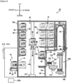
- FIGS. 1 and 2 are diagrams schematically illustrating a substrate processing apparatus 10 according to the present embodiments.
- the substrate processing apparatus 10 is configured as a vertical type apparatus configured to perform a process such as an oxidation process, a diffusion process and a CVD (Chemical Vapor Deposition) process on a substrate 2.
- a FOUP Front Opening Unified Pod, hereinafter also referred to as a "container 4”
- the substrate 2 is made of a material such as silicon (Si).
- the substrate processing apparatus 10 is provided with the substrate processing apparatus main structure 12.
- a loading/unloading structure 14 configured to transfer (load) the container 4 into and to transfer (unload) the container 4 out of the substrate processing apparatus main structure 12 is provided.
- a loading/unloading port 16 configured to communicate between an inside (inner portion) and an outside (outer portion) of the substrate processing apparatus main structure 12 is provided.
- the loading/unloading port 16 is configured to be opened and closed by an opening/closing structure (also referred to as an "opener/closer") 18.
- the substrate transfer apparatus 110 is provided in an inner space of the sub-housing 40.
- the substrate transfer apparatus 110 is configured to transfer the substrate 2 between the substrate loading port structure 60 and the boat 104.
- the first linear mover 141 is connected to the second linear mover 143 and the first rotator 142, and is a linear mover configured to linearly move the tweezers 122 in the horizontal direction of the second linear mover 143 (in the front-rear direction when the first rotator 142 is at an original position).
- the first rotator 142 is connected to the first linear mover 141 and the third linear mover 144, and is a rotator configured to rotate the tweezers 122 around a rotation shaft extending in the up-down direction of the first linear mover 141 and the second linear mover 143.
- the third linear mover 144 is connected to the first rotator 142 and the base 112, and is a linear mover configured to linearly move the tweezers 122 in the up-down direction of the first linear mover 141, the first rotator 142, and the second linear mover 143.
- the substrate transfer apparatus 110 is a transporter provided with a total of four transfer shafts, that is, a transfer shaft for driving in the front-rear direction, two transfer shafts for driving in the up-down direction and a transfer shaft for rotation around a rotation shaft extending in the up-down direction.
- the first rotator 142 is an example of a rotation shaft capable of rotating according to the present embodiments.
- the first linear mover 141 is an example of a front-rear shaft capable of moving in the front-rear direction according to the present embodiments.
- the second linear mover 143 is an example of a vertical shaft capable of moving in the up-down direction according to the present embodiments.
- the third linear mover 144 is an example of a vertical shaft capable of moving in the up-down direction according to the present embodiments.
- a configuration among the first linear mover 141 to the seventh linear mover 149, the first rotator 142 and the second rotator 148 may also be simply referred to as a "transfer structure".
- "selecting or operating the transfer structure” refers to “selecting or operating the transfer shaft of the transfer structure”.
- the controller 200 may include: a CPU (Central Processing Unit) 201 serving as an example of a processor; and a RAM (Random Access Memory) 202 used as a temporary work area for the CPU 201. Further, the controller 200 functions as a determination processor 203 described later when a control program is executed by the CPU 201.
- the controller 200 may further include: a memory 204 configured to store the control program (which causes the CPU 201 to function as the controller 200) and an I/O port (input/output port) 205.
- the CPU 201, the RAM 202, the memory 204 and the I/O port 205 are connected to one another via a bus (not shown).
- the process controller 220 is a control apparatus configured to control the substrate processing apparatus 10 to execute a processing procedure for the substrate 2.
- the process controller 220 is connected to apparatuses such as a temperature measuring apparatus (not shown), a pressure measuring apparatus (not shown) and a gas control apparatus (not shown) configured to control a supply of a gas such as a process gas and an inert gas used to process the substrate 2.
- linear mover driver refers to a control apparatus configured to control the transfer structure when the transporter moves in a specific direction.
- first linear mover driver 241 to the seventh linear mover driver 249 correspond to the first linear mover 141 to the seventh linear mover 149, respectively.
- the first linear mover driver 241 shown in FIG. 3 drives the first linear mover 141 configured to move the tweezers shown in FIGS. 1 and 2 in the front-rear direction when instructed by the controller 200.
- the same also applies to the other linear mover drivers and the rotators mentioned above.
- the external communication interface 210 is connected to a communication line and provided with a communication protocol for transmitting and receiving data to and from an external apparatus (not shown) connected to the same communication line.
- the external communication interface 210 performs data communication with the external apparatus in accordance with an instruction from the CPU 201 in the controller 200.
- the external memory 211 is an apparatus capable of storing various data and the like, and is provided separately from the memory 204 of the controller 200.
- a specific configuration of the external memory 211 is not particularly limited. However, for example, a storage apparatus such as a network attached storage (NAS) connected via a network or a portable recording medium such as an SD memory card may be used as the external memory 211.
- NAS network attached storage
- the manipulator 212 is an apparatus configured to receive an instruction from the operator and further configured to notify the CPU 201 (of the controller 200) of the instruction received in a manner described above.
- a button provided on a housing of the substrate processing apparatus 10 or an operation pendant connected to the substrate processing apparatus 10 may be used as the manipulator 212.
- the display 213 is an apparatus configured to display information about the substrate processing apparatus 10.
- a configuration such as a liquid crystal display and an organic EL (Electro Luminescence) display may be used as the display 213.
- the manipulator 212 and the display 213 of the present embodiments will be described by way of an example in which a touch panel capable of being operated by touching a screen thereof by the operator, as shown in FIG. 4 described later, is used.
- the touch panel of the present embodiments is an apparatus configured to serve as both of the display 213 and the manipulator 212. Contents displayed on the touch panel will be described in detail later.
- each configuration connected to the I/O port 205 is merely an example, and a configuration corresponding to the function of the substrate processing apparatus 10 is connected the I/O port 205.
- the configuration corresponding to the function of the substrate processing apparatus 10 may refer to an execution configuration configured to execute a processing under a control of a processor such as the CPU 201 and the RAM 202.
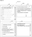
- a transfer shaft selection area 215, a start-up procedure display area 217, a work procedure display area 216 and a progress status display area 218 are displayed on the screen of the display 213.
- each of the items AI may also be referred to as an "item AI". More specifically, in the transfer shaft selection area 215, names of the transfer structures of the substrate processing apparatus 10 are aligned vertically as an example of the items AI. Further, the items AI of the transfer structures displayed in the transfer shaft selection area 215 can be selected by the operator using the touch panel. Further, the controller 200 distinguishes an item AI (which is selected by the operator) from the other items AI (which are not selected by the operator) by surrounding the item with a frame F.
- the item AI is also marked with a mark indicating a state of the transfer structure related thereto.
- the controller 200 switches a displayed image of the item AI (which is selected) by adding the frame F to the item AI (which is selected).
- the frame F is a display for distinguishing the item AI (which is selected) from the other items AI (which are not selected). For example, a border of the frame F may be displayed. Instead of displaying the border of the frame F, a background of an area indicated by the frame F, that is, an area corresponding to the item AI (which is selected) may be displayed differently from the other items AI (which are not selected).
- the transfer structure when a calibration is performed for the transfer structure and a distance from the transfer structure to the original position in the mechanical coordinates of the substrate processing apparatus 10 is known, the transfer structure is marked with a mark "C", indicating a state in which a position setting is complete.
- the transfer structure is marked with a mark "I”, indicating a state in which a position setting is incomplete.
- the transfer structure is marked with a mark "A”, indicating a state in which the line is disconnected.
- the transfer structure when the transfer structure cannot be selected for a reason described later, the item AI representing the transfer structure (which cannot be selected) is displayed lightly as an unselectable display "D", thereby indicating that the transfer structure cannot be selected.
- the transfer structures other than the first linear mover 141 are displayed lightly as the unselectable display D.
- a work procedure (which is processing contents of the procedure displayed by the frame F in the start start-up procedure display area 217 for the transfer structure selected by the operator in the transfer shaft selection area 215) is displayed as a work item "WI".
- the controller 200 switches a displayed image of the work item WI (which represents a work being performed) to a different display from the other work items WI by adding the frame F to the work item AI.
- the controller 200 switches the displayed image of the work procedure in accordance with the work being performed by adding the frame F to the work item WI.
- the controller 200 When the procedure executed by the controller 200 moves on, new items are added and displayed in the progress status display area 218.
- the controller 200 adds and displays the new items, thereby switching a displayed image of the progress status display area 218 to show a work progress status in accordance with the work being performed.
- the mounting table 20 When the container 4 is placed on the mounting table 20 at the loading/unloading position, the mounting table 20 is moved to the transfer position by the transfer structure 22. Accordingly, the container 4 is loaded into the substrate processing apparatus main structure 12 through the loading/unloading port 16.
- the container 4 loaded into the substrate processing apparatus main structure 12 is transferred by the container transfer apparatus 70 from the mounting table 20 to a predetermined position on the buffer shelf 30 or the container storage shelf 50, where the container 4 is temporarily stored.
- the container 4 stored on the buffer shelf 30 or the container storage shelf 50 is transferred by the container transfer apparatus 70 to a predetermined substrate loading port structure (that is, one of an upper and lower substrate loading port structures) 60 among the two substrate loading port structures 60.
- the predetermined substrate loading port structure 60 may also be simply referred to as the "substrate loading port structure 60".
- the container 4 may be transferred directly from the mounting table 20 to the substrate loading port structure 60.
- the lid of the container 4 transferred into the substrate loading port structure 60 is opened by the container opening/closing apparatus 62.
- another container 4 is transferred to the other substrate loading port structure 60 (that is, the other one of the upper and lower substrate loading port structures).
- the substrates 2 accommodated in the container 4 are transferred (loaded) into the boat 104 by the substrate transfer apparatus 110.
- the containers 4 are repeatedly supplied to the substrate loading port structure 60. In a state where the substrates 2 accommodated in the containers 4 are held (supported) in the boat 104, the substrates 2 are batch-processed.
- the transfer structure which can be operated by the operator is limited to a predetermined transfer structure.
- the determination processor 203 configured by the program executed by the CPU 201 of the controller 200 determines that the calibration work can be performed on another transfer structure when the operator has completed the calibration work on the first linear mover 141.
- the determination processor 203 determines that the calibration work cannot be performed on another transfer structure when the operator has not completed the calibration work on the first linear mover 141.
- the first linear mover 141 may be regarded as the predetermined transfer structure in the present embodiments.
- the procedures of the calibration work may be performed by simultaneously operating a plurality of transfer structures and simultaneously setting the original position of each of the plurality of transfer structures. Thereby, it is possible to shorten a work time.
- the transfer structure which can be operated by the operator is limited to the predetermined transfer structure and that the operator is forced to calibrate the transfer structures one by one.
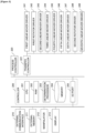
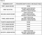
- FIG. 6 is a diagram schematically illustrating a correspondence table stored in the memory 204 according to the present embodiments.
- the correspondence table indicates transfer structures selectable at the same time. More specifically, when the operator selects a specified transfer structure among the transfer structures listed in the left column shown in FIG. 6 , the CPU 201 set transfer structures other than those in the right column to be non-selectable. For example, in FIG. 6 , when the first rotator 142 is selected as the specified transfer structure, transfer structures other than the second linear mover 143, the third linear mover 144 and the seventh linear mover 149 are set to be non-selectable. In addition, for example, in FIG.
- the correspondence table shown in FIG. 6 is an example of predefined parameters in the present embodiments.
- the CPU 201 switches the displayed image on the display 213 together with another configuration to notify whether or not another transfer structure can be selected.
- the procedures executed by the controller 200 will be described with reference to FIG. 7 .
- the manipulator 212 when the operator selects a specified transfer structure among the transfer structures displayed in the transfer shaft selection area 215, the manipulator 212 notifies the determination processor 203 of the specified transfer structure (selected transfer structure) in a sequence S202. In a sequence S204, the manipulator 212 also notifies the display 213 of the specified transfer structure.
- the determination processor 203 determines, based on the correspondence table, whether or not there is a transfer structure (or there are transfer structures) that can be selected simultaneously with the specified transfer structure. In other words, in the sequence S206, the determination processor 203 determines whether or not another transfer structure is valid (that is, selectable). That is, a procedure of the sequence S206 is an example of a determination step of determining whether the initial position setting for the specified transfer structure (that is, the transfer structure selected by the manipulator 212 in the present embodiments) has been completed and determining whether or not the initial position setting for another transfer structure can be performed in parallel with the initial position setting for the specified transfer structure.
- the display 213 displays the specified transfer structure by adding the frame F to the specified transfer structure selected among the transfer structures displayed in the transfer shaft selection area 215.
- a procedure of the sequence S212 is an example of a step of notifying the determination result in the determination step in the present embodiments.
- the display 213 displays that the other transfer structures (except for the transfer structures which are selectable and whose information was transmitted in the sequence S212 from the determination processor unit 203) are unselectable. More specifically, in the sequence S214, the display 213 lightly displays the other transfer structures (except for the transfer structures which are selectable) as the unselectable display D, as shown in the transfer shaft selection area 215 in FIG. 8 .
- the determination processor 203 determines, in the sequence S206, that another transfer structure is not valid (that is, unselectable)
- the sequence S212 is not executed.
- the other transfer structures except for the transfer structures which are selectable
- the display 213 such an operation is another example of a process for notifying the determination result in the determination process in this embodiment.
- the controller 200 performs the calibration for the plurality of transporters provided with the plurality of transfer structures by executing a series of procedures mentioned above with the CPU 201. Further, the series of procedures mentioned above can be executed for any of the transfer structures of the substrate processing apparatus 10. Therefore it can be regarded that the entire transfer structures are initially set by the series of procedures mentioned above.
- the initial position setting for each of the transfer structures of each transporter is completed. For example, when the procedure of the initial position setting for each of the transfer structures of each transporter is incorrect, the substrate processing apparatus 10 may not operate normally.
- the substrate processing apparatus 10 of the present embodiments it is possible to reduce the burden on the operator because the operator can select, by the manipulator 212, one or more transfer structures for which the initial position can be set by looking at the transfer structures displayed on the display 213.
- the determination processor 203 determines whether the initial position setting for the specified transfer structure (selected transfer structure) is valid or invalid, and the controller 200 selectively controls the drive shaft determined to be valid to perform the initial position setting for the transfer structure.
- the controller 200 notifies the operator that the initial position setting for the specified transfer structure is invalid, it is possible to prevent inconvenience caused by the initial position setting operation related thereto.
- the substrate processing apparatus 10 of the present embodiments by checking whether the initial position of the predetermined transfer structure is set before operating another transfer structure, it is possible to avoid collisions between the transporters and it is also possible to improve a work safety.
- the parameters of other shafts (which are selectable) that can be selected together with the selected shaft related to the specified transfer structure are set, it is possible to easily check one or more selectable shafts that can be selected together with the selected shaft by referring to the parameters. Further, since the parameters are editable, it is possible to set the selectable shafts depending on an apparatus configuration.
- Each transporter is provided with various transfer apparatuses, and each transfer apparatus is provided with a plurality of transfer structures.
- the initial settings for each shaft of various transfer apparatuses can be displayed together. Thereby, it is possible to set the initial position of each drive shaft in parallel. Further, it is possible to reduce the burden on the operator and it is also possible to prevent the settings of the drive shafts from being omitted.
- each transporter is provided with a plurality of transfer structures, and the display 213 can be used to set the initial positions of the plurality of transfer structures.
- the substrate processing apparatus 10 of the present embodiments it is possible to select a plurality of transfer structures for which the initial position setting can be performed. Thereby, it is possible to contribute to improving the work efficiency when setting up the apparatus.
- the substrate processing apparatus 10 of the present embodiments when a specific shaft is selected, it is possible to select another shaft which can be set in parallel with the specific shaft by referring to the parameters. Then, by selecting a plurality of other shafts, each shaft selected in manner described above can be changed and the initial setting can be performed.
- the substrate processing apparatus 10 of the present embodiments by setting the initial positions of the plurality of shafts in parallel, it is possible to contribute to reducing the number of steps for the initial setting for the shafts.
- the initial position setting is also performed on the substrate transfer apparatus 110 serving as the transporter.
- the initial position setting for the substrate transfer apparatus 110 can be performed in parallel with that of another transfer structure. Thereby, it is possible to contribute to improving the work efficiency when setting up the apparatus. Further, the initial position setting for a plurality of transfer structures is performed within a range where the safety can be confirmed by the determination processor 203. Therefore, it is possible to avoid problems such as collisions between the transfer structures.
- the initial position setting is also performed on the container transfer apparatus 70 serving as the transporter.
- the initial position setting for the container transfer apparatus 70 can be performed in parallel with that of another transfer structure. Thereby, it is possible to contribute to improving the work efficiency when setting up the apparatus. Further, the initial position setting for a plurality of transfer structures is performed within a range where the safety can be confirmed by the determination processor 203. Therefore, it is possible to avoid the problems such as the collisions between the transfer structures.
- the substrate processing apparatus 10 of the present embodiments it is possible to clarify the transfer structure. Thereby, it is possible for the operator to easily check the transfer structure.
- the substrate processing apparatus 10 of the present embodiments by selecting the transfer structure, it is possible for the operator to easily perform the initial position setting for the transfer structure.
- the substrate processing apparatus 10 of the present embodiments it is possible to clarify the transfer structure (which is selected). Thereby, it is possible to easily check the transfer structure (which is selected).
- the substrate processing apparatus 10 of the present embodiments by displaying the work procedure in the work procedure display area 216, it is possible to clarify a flow of the work. Further, even an inexperienced operator can check the work.
- the substrate processing apparatus 10 of the present embodiments by checking the status of each transfer structure, it is possible to easily clarify the transfer structure for which the initial position setting is performed.
- the display 213 is provided with the transfer shaft selection area 215 in which the plurality of items AI can be aligned and displayed.
- the technique of the present disclosure is not limited thereto.
- the display 213 may be constituted by a plurality of lamps, and the transporters may correspond to the lamps, respectively.
- the display 213 displays the item AI of the transfer structure.
- the technique of the present disclosure is not limited thereto.
- the display 213 may not be provided with a screen display, and the transfer structure may be indicated by a lamp which is turned on or off.
- the transfer structure corresponding to the item AI is selected.
- the technique of the present disclosure is not limited thereto.
- the display 213 and the manipulator 212 may be provided separately, and the transfer structure may not be selected even when the item AI on the display 213 is operated.
- the controller 200 aligns and displays the work items WI indicating the work procedure for the initial position setting for the transfer structure (which is selected in the transfer shaft selection area 215) in the work procedure display area 216.
- the technique of the present disclosure is not limited thereto.
- the controller 200 may not display the work items WI indicating the work procedure for the initial position setting for the transfer structure in the work procedure display area 216.
- the controller 200 may also display the work items WI of the entirety of transfer structures in the work procedure display area 216 without being limited to the transfer structure (which is selected).
- the controller 200 switches the displayed image of the work item WI (which represents the work being performed) displayed in the work procedure display area 216 to a different display from the other work items WI.
- the technique of the present disclosure is not limited thereto.
- the controller 200 may control the display of the work item WI of the transfer structure (which is selected) and the display of the work item WI of another transfer structure (which is not selected) in a same manner.
- the controller 200 switches and shows the work progress status in accordance with the work being performed.
- the technique of the present disclosure is not limited thereto.
- the controller 200 may not display the work progress status on the screen.
- the display 213 can display the state in which the line is disconnected, the state in which the position setting is incomplete and the state in which the position setting is complete.
- the technique of the present disclosure is not limited thereto.
- the display 213 may not display one or more among the state in which the line is disconnected, the state in which the position setting is incomplete and the state in which the position setting is complete.
- the entire states exemplified above may not be displayed.
- the controller 200 when the line of any one of the transfer structures is disconnected, the controller 200 set the transfer structure whose line is disconnected to be unselectable.
- the technique of the present disclosure is not limited thereto.
- the controller 200 may set the transfer structure whose line is disconnected to be selectable without switching the image on the screen display.
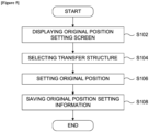
- the manipulator 212 is configured to be controlled to store the information about the initial position in the memory 204 when the initial position setting is normally completed.
- the technique of the present disclosure is not limited thereto.
- the initial position setting may be automatically stored in the memory 204 by the controller 200 without receiving an operation by the manipulator 212 from the operator.
- the program is stored in the memory 204.
- a method of providing the program according to the present disclosure is not limited thereto.
- the program may be recorded in a computer-readable recording medium and provided together with the recording medium.
- the embodiments mentioned above are described by way of an example in which a batch type substrate processing apparatus capable of simultaneously processing a plurality of substrates is used to form the film.
- the technique of the present disclosure is not limited thereto.
- the technique of the present disclosure may be preferably applied when a single wafer type substrate processing apparatus capable of simultaneously processing one or several substrates is used to form the film.
- the embodiments mentioned above are described by way of an example in which a substrate processing apparatus including a hot wall type process furnace is used to form the film.
- the technique of the present disclosure is not limited thereto.
- the technique of the present disclosure may be preferably applied when a substrate processing apparatus including a cold wall type process furnace is used to form the film.
- the technique of the present disclosure is not limited thereto.
- the technique of the present disclosure may also be applied to a semiconductor manufacturing apparatus such as a batch and vertical type diffusion apparatus.
- the technique of the present disclosure is not limited thereto.
- a cassette which does not include a cap (or a lid) may be used as the substrate container.
- the cassette is used as the substrate container, it is possible to omit an installation operation for the container opening/closing apparatus 62.
- a loading structure through which the substrate is loaded into the substrate processing apparatus main structure 12 and an unloading structure through which the substrate is unloaded out of the substrate processing apparatus main structure 12 may be provided separately instead of the loading/unloading structure 14, and the transfer structure 22 may be provided at one or both of the loading structure and the unloading structure.
- the substrate loading port structures 60 are not limited to the upper and lower substrate loading port structures arranged in two stages.
- a substrate loading port structure may be arranged in one stage alone.
- three or more substrate loading port structures arranged in three or more stages may be provided.
- the invention may be summarized as follows: It is possible to suppress a decrease in work efficiency in an initial position setting operation for a substrate processing apparatus.
- a technique that includes: transporters each provided with one or more transfer shafts; a manipulator for selecting a specified transfer shaft from the one or more transfer shafts and performing an initial position setting therefor; a display for displaying a status of the initial position setting for the specified transfer shaft; and a controller including a determination processor and notifying a determination result determined by the determination processor, wherein the determination processor determines whether the initial position setting for the specified transfer shaft selected by the manipulator is completed and whether it is possible for an initial position setting for another transfer shaft to be performed in parallel.
Landscapes
- Engineering & Computer Science (AREA)
- Chemical & Material Sciences (AREA)
- Automation & Control Theory (AREA)
- Manufacturing & Machinery (AREA)
- General Physics & Mathematics (AREA)
- Physics & Mathematics (AREA)
- Human Computer Interaction (AREA)
- Materials Engineering (AREA)
- Organic Chemistry (AREA)
- Metallurgy (AREA)
- Mechanical Engineering (AREA)
- Chemical Kinetics & Catalysis (AREA)
- General Chemical & Material Sciences (AREA)
- General Engineering & Computer Science (AREA)
- Quality & Reliability (AREA)
- Computer Hardware Design (AREA)
- Microelectronics & Electronic Packaging (AREA)
- Container, Conveyance, Adherence, Positioning, Of Wafer (AREA)
- Robotics (AREA)
Applications Claiming Priority (1)
| Application Number | Priority Date | Filing Date | Title |
|---|---|---|---|
| JP2024000737A JP2025107031A (ja) | 2024-01-05 | 2024-01-05 | 基板処理装置、半導体装置の製造方法、及びプログラム |
Publications (2)
| Publication Number | Publication Date |
|---|---|
| EP4583154A2 true EP4583154A2 (de) | 2025-07-09 |
| EP4583154A3 EP4583154A3 (de) | 2025-07-30 |
Family
ID=93926014
Family Applications (1)
| Application Number | Title | Priority Date | Filing Date |
|---|---|---|---|
| EP24221274.4A Pending EP4583154A3 (de) | 2024-01-05 | 2024-12-18 | Substratverarbeitungsvorrichtung, verfahren zur herstellung eines halbleiterbauelements und programm |
Country Status (6)
| Country | Link |
|---|---|
| US (1) | US20250224704A1 (de) |
| EP (1) | EP4583154A3 (de) |
| JP (1) | JP2025107031A (de) |
| KR (1) | KR20250107720A (de) |
| CN (1) | CN120280386A (de) |
| TW (1) | TW202534851A (de) |
Citations (1)
| Publication number | Priority date | Publication date | Assignee | Title |
|---|---|---|---|---|
| JP2012169534A (ja) | 2011-02-16 | 2012-09-06 | Hitachi Kokusai Electric Inc | 基板処理装置及び半導体装置の製造方法 |
Family Cites Families (2)
| Publication number | Priority date | Publication date | Assignee | Title |
|---|---|---|---|---|
| JP2013161837A (ja) * | 2012-02-02 | 2013-08-19 | Hitachi Kokusai Electric Inc | 半導体製造装置、基板移載装置及び半導体装置の製造方法 |
| JP7387316B2 (ja) * | 2019-07-19 | 2023-11-28 | 株式会社Screenホールディングス | 基板処理システムおよび基板搬送方法 |
-
2024
- 2024-01-05 JP JP2024000737A patent/JP2025107031A/ja active Pending
- 2024-10-09 CN CN202411399588.2A patent/CN120280386A/zh active Pending
- 2024-12-02 TW TW113146563A patent/TW202534851A/zh unknown
- 2024-12-12 KR KR1020240184943A patent/KR20250107720A/ko active Pending
- 2024-12-16 US US18/982,104 patent/US20250224704A1/en active Pending
- 2024-12-18 EP EP24221274.4A patent/EP4583154A3/de active Pending
Patent Citations (1)
| Publication number | Priority date | Publication date | Assignee | Title |
|---|---|---|---|---|
| JP2012169534A (ja) | 2011-02-16 | 2012-09-06 | Hitachi Kokusai Electric Inc | 基板処理装置及び半導体装置の製造方法 |
Also Published As
| Publication number | Publication date |
|---|---|
| KR20250107720A (ko) | 2025-07-14 |
| CN120280386A (zh) | 2025-07-08 |
| TW202534851A (zh) | 2025-09-01 |
| EP4583154A3 (de) | 2025-07-30 |
| JP2025107031A (ja) | 2025-07-17 |
| US20250224704A1 (en) | 2025-07-10 |
Similar Documents
| Publication | Publication Date | Title |
|---|---|---|
| US9437465B2 (en) | Substrate processing apparatus and method of manufacturing semiconductor device | |
| JP5224744B2 (ja) | 基板処理装置 | |
| KR101043986B1 (ko) | 기판 처리 시스템 및 군(群) 관리 시스템 | |
| JP4917660B2 (ja) | 基板処理装置、基板処理装置の制御方法、半導体デバイスの製造方法、装置状態遷移方法、基板処理装置の保守方法及び状態遷移プログラム | |
| US20260068590A1 (en) | Substrate processing apparatus and method of manufacturing semiconductor device | |
| JP5412065B2 (ja) | 情報管理方法、情報管理装置及び基板処理システム | |
| TW201133165A (en) | Substrate processing system | |
| JP2010074141A (ja) | 基板処理装置及び半導体装置の製造方法 | |
| EP4583154A2 (de) | Substratverarbeitungsvorrichtung, verfahren zur herstellung eines halbleiterbauelements und programm | |
| CN110783243B (zh) | 基板处理装置、半导体器件的制造方法及记录介质 | |
| JP2009231748A (ja) | 基板処理装置 | |
| JP2012060168A (ja) | 基板処理装置、基板処理装置のメンテナンス方法、基板処理装置の制御方法、基板処理装置の保守方法、半導体装置の製造方法及び装置状態遷移方法 | |
| JP4734185B2 (ja) | 基板処理装置及び基板処理装置の制御方法 | |
| JP5478033B2 (ja) | 基板処理装置、基板処理装置の制御方法、条件設定プログラム及び半導体装置の製造方法 | |
| US20260023370A1 (en) | Processing system, substrate processing apparatus, processing method, method of manufacturing semiconductor device and non-transitory computer-readable recording medium | |
| US20240338015A1 (en) | Controlling apparatus, substrate processing apparatus, method of manufacturing semiconductor device, and recording medium | |
| EP4517613A1 (de) | Verarbeitungsvorrichtung, substratverarbeitungsvorrichtung, anzeigeverfahren, substratverarbeitungsverfahren, verfahren zur herstellung eines halbleiterbauelements und programm | |
| JP5546195B2 (ja) | 基板処理装置、基板処理装置の表示方法及び半導体装置の製造方法 | |
| EP4435545A1 (de) | Steuerungsvorrichtung, substratverarbeitungsvorrichtung, verfahren zur herstellung eines halbleiterbauelements und programm | |
| EP4528409A1 (de) | Anzeigeverarbeitungsvorrichtung, substratverarbeitungsvorrichtung, anzeigeverfahren, substratverarbeitungsverfahren, verfahren zur herstellung eines halbleiterbauelements und programm | |
| JP2009088349A (ja) | 基板処理装置 | |
| JP2011204865A (ja) | 基板処理装置 | |
| JP2006085531A (ja) | 基板処理装置 | |
| JP2012104700A (ja) | 基板処理システム | |
| JP2009253217A (ja) | 基板処理装置 |
Legal Events
| Date | Code | Title | Description |
|---|---|---|---|
| PUAI | Public reference made under article 153(3) epc to a published international application that has entered the european phase |
Free format text: ORIGINAL CODE: 0009012 |
|
| STAA | Information on the status of an ep patent application or granted ep patent |
Free format text: STATUS: THE APPLICATION HAS BEEN PUBLISHED |
|
| PUAL | Search report despatched |
Free format text: ORIGINAL CODE: 0009013 |
|
| AK | Designated contracting states |
Kind code of ref document: A2 Designated state(s): AL AT BE BG CH CY CZ DE DK EE ES FI FR GB GR HR HU IE IS IT LI LT LU LV MC ME MK MT NL NO PL PT RO RS SE SI SK SM TR |
|
| AK | Designated contracting states |
Kind code of ref document: A3 Designated state(s): AL AT BE BG CH CY CZ DE DK EE ES FI FR GB GR HR HU IE IS IT LI LT LU LV MC ME MK MT NL NO PL PT RO RS SE SI SK SM TR |
|
| RIC1 | Information provided on ipc code assigned before grant |
Ipc: H01L 21/67 20060101AFI20250623BHEP Ipc: H01L 21/673 20060101ALI20250623BHEP Ipc: H01L 21/677 20060101ALI20250623BHEP |
|
| P01 | Opt-out of the competence of the unified patent court (upc) registered |
Free format text: CASE NUMBER: UPC_APP_0010532_4583154/2025 Effective date: 20251021 |
|
| STAA | Information on the status of an ep patent application or granted ep patent |
Free format text: STATUS: REQUEST FOR EXAMINATION WAS MADE |
|
| 17P | Request for examination filed |
Effective date: 20251223 |