EP4435545A1 - Steuerungsvorrichtung, substratverarbeitungsvorrichtung, verfahren zur herstellung eines halbleiterbauelements und programm - Google Patents
Steuerungsvorrichtung, substratverarbeitungsvorrichtung, verfahren zur herstellung eines halbleiterbauelements und programm Download PDFInfo
- Publication number
- EP4435545A1 EP4435545A1 EP24161965.9A EP24161965A EP4435545A1 EP 4435545 A1 EP4435545 A1 EP 4435545A1 EP 24161965 A EP24161965 A EP 24161965A EP 4435545 A1 EP4435545 A1 EP 4435545A1
- Authority
- EP
- European Patent Office
- Prior art keywords
- event
- display
- item
- substrate
- occurred
- Prior art date
- Legal status (The legal status is an assumption and is not a legal conclusion. Google has not performed a legal analysis and makes no representation as to the accuracy of the status listed.)
- Pending
Links
Images





Classifications
-
- G—PHYSICS
- G05—CONTROLLING; REGULATING
- G05B—CONTROL OR REGULATING SYSTEMS IN GENERAL; FUNCTIONAL ELEMENTS OF SUCH SYSTEMS; MONITORING OR TESTING ARRANGEMENTS FOR SUCH SYSTEMS OR ELEMENTS
- G05B23/00—Testing or monitoring of control systems or parts thereof
- G05B23/02—Electric testing or monitoring
- G05B23/0205—Electric testing or monitoring by means of a monitoring system capable of detecting and responding to faults
- G05B23/0259—Electric testing or monitoring by means of a monitoring system capable of detecting and responding to faults characterized by the response to fault detection
- G05B23/0267—Fault communication, e.g. human machine interface [HMI]
-
- H—ELECTRICITY
- H10—SEMICONDUCTOR DEVICES; ELECTRIC SOLID-STATE DEVICES NOT OTHERWISE PROVIDED FOR
- H10P—GENERIC PROCESSES OR APPARATUS FOR THE MANUFACTURE OR TREATMENT OF DEVICES COVERED BY CLASS H10
- H10P72/00—Handling or holding of wafers, substrates or devices during manufacture or treatment thereof
- H10P72/06—Apparatus for monitoring, sorting, marking, testing or measuring
- H10P72/0606—Position monitoring, e.g. misposition detection or presence detection
- H10P72/0608—Position monitoring, e.g. misposition detection or presence detection of substrates stored in a container, a magazine, a carrier, a boat or the like
-
- G—PHYSICS
- G05—CONTROLLING; REGULATING
- G05B—CONTROL OR REGULATING SYSTEMS IN GENERAL; FUNCTIONAL ELEMENTS OF SUCH SYSTEMS; MONITORING OR TESTING ARRANGEMENTS FOR SUCH SYSTEMS OR ELEMENTS
- G05B23/00—Testing or monitoring of control systems or parts thereof
- G05B23/02—Electric testing or monitoring
- G05B23/0205—Electric testing or monitoring by means of a monitoring system capable of detecting and responding to faults
- G05B23/0259—Electric testing or monitoring by means of a monitoring system capable of detecting and responding to faults characterized by the response to fault detection
- G05B23/0267—Fault communication, e.g. human machine interface [HMI]
- G05B23/0272—Presentation of monitored results, e.g. selection of status reports to be displayed; Filtering information to the user
-
- G—PHYSICS
- G05—CONTROLLING; REGULATING
- G05B—CONTROL OR REGULATING SYSTEMS IN GENERAL; FUNCTIONAL ELEMENTS OF SUCH SYSTEMS; MONITORING OR TESTING ARRANGEMENTS FOR SUCH SYSTEMS OR ELEMENTS
- G05B19/00—Program-control systems
- G05B19/02—Program-control systems electric
- G05B19/418—Total factory control, i.e. centrally controlling a plurality of machines, e.g. direct or distributed numerical control [DNC], flexible manufacturing systems [FMS], integrated manufacturing systems [IMS] or computer integrated manufacturing [CIM]
- G05B19/4183—Total factory control, i.e. centrally controlling a plurality of machines, e.g. direct or distributed numerical control [DNC], flexible manufacturing systems [FMS], integrated manufacturing systems [IMS] or computer integrated manufacturing [CIM] characterised by data acquisition, e.g. workpiece identification
-
- G—PHYSICS
- G05—CONTROLLING; REGULATING
- G05B—CONTROL OR REGULATING SYSTEMS IN GENERAL; FUNCTIONAL ELEMENTS OF SUCH SYSTEMS; MONITORING OR TESTING ARRANGEMENTS FOR SUCH SYSTEMS OR ELEMENTS
- G05B19/00—Program-control systems
- G05B19/02—Program-control systems electric
- G05B19/418—Total factory control, i.e. centrally controlling a plurality of machines, e.g. direct or distributed numerical control [DNC], flexible manufacturing systems [FMS], integrated manufacturing systems [IMS] or computer integrated manufacturing [CIM]
- G05B19/41835—Total factory control, i.e. centrally controlling a plurality of machines, e.g. direct or distributed numerical control [DNC], flexible manufacturing systems [FMS], integrated manufacturing systems [IMS] or computer integrated manufacturing [CIM] characterised by program execution
-
- G—PHYSICS
- G05—CONTROLLING; REGULATING
- G05B—CONTROL OR REGULATING SYSTEMS IN GENERAL; FUNCTIONAL ELEMENTS OF SUCH SYSTEMS; MONITORING OR TESTING ARRANGEMENTS FOR SUCH SYSTEMS OR ELEMENTS
- G05B23/00—Testing or monitoring of control systems or parts thereof
- G05B23/02—Electric testing or monitoring
- G05B23/0205—Electric testing or monitoring by means of a monitoring system capable of detecting and responding to faults
- G05B23/0208—Electric testing or monitoring by means of a monitoring system capable of detecting and responding to faults characterized by the configuration of the monitoring system
- G05B23/0216—Human interface functionality, e.g. monitoring system providing help to the user in the selection of tests or in its configuration
-
- G—PHYSICS
- G05—CONTROLLING; REGULATING
- G05B—CONTROL OR REGULATING SYSTEMS IN GENERAL; FUNCTIONAL ELEMENTS OF SUCH SYSTEMS; MONITORING OR TESTING ARRANGEMENTS FOR SUCH SYSTEMS OR ELEMENTS
- G05B23/00—Testing or monitoring of control systems or parts thereof
- G05B23/02—Electric testing or monitoring
- G05B23/0205—Electric testing or monitoring by means of a monitoring system capable of detecting and responding to faults
- G05B23/0259—Electric testing or monitoring by means of a monitoring system capable of detecting and responding to faults characterized by the response to fault detection
- G05B23/0267—Fault communication, e.g. human machine interface [HMI]
- G05B23/027—Alarm generation, e.g. communication protocol; Forms of alarm
-
- H—ELECTRICITY
- H10—SEMICONDUCTOR DEVICES; ELECTRIC SOLID-STATE DEVICES NOT OTHERWISE PROVIDED FOR
- H10P—GENERIC PROCESSES OR APPARATUS FOR THE MANUFACTURE OR TREATMENT OF DEVICES COVERED BY CLASS H10
- H10P72/00—Handling or holding of wafers, substrates or devices during manufacture or treatment thereof
- H10P72/30—Handling or holding of wafers, substrates or devices during manufacture or treatment thereof for conveying, e.g. between different workstations
- H10P72/34—Handling or holding of wafers, substrates or devices during manufacture or treatment thereof for conveying, e.g. between different workstations the wafers being stored in a carrier, involving loading and unloading
- H10P72/3404—Storage means
-
- H—ELECTRICITY
- H10—SEMICONDUCTOR DEVICES; ELECTRIC SOLID-STATE DEVICES NOT OTHERWISE PROVIDED FOR
- H10P—GENERIC PROCESSES OR APPARATUS FOR THE MANUFACTURE OR TREATMENT OF DEVICES COVERED BY CLASS H10
- H10P72/00—Handling or holding of wafers, substrates or devices during manufacture or treatment thereof
- H10P72/30—Handling or holding of wafers, substrates or devices during manufacture or treatment thereof for conveying, e.g. between different workstations
- H10P72/34—Handling or holding of wafers, substrates or devices during manufacture or treatment thereof for conveying, e.g. between different workstations the wafers being stored in a carrier, involving loading and unloading
- H10P72/3406—Handling or holding of wafers, substrates or devices during manufacture or treatment thereof for conveying, e.g. between different workstations the wafers being stored in a carrier, involving loading and unloading involving removal of lid, door or cover
-
- G—PHYSICS
- G05—CONTROLLING; REGULATING
- G05B—CONTROL OR REGULATING SYSTEMS IN GENERAL; FUNCTIONAL ELEMENTS OF SUCH SYSTEMS; MONITORING OR TESTING ARRANGEMENTS FOR SUCH SYSTEMS OR ELEMENTS
- G05B2219/00—Program-control systems
- G05B2219/20—Pc systems
- G05B2219/23—Pc programming
- G05B2219/23136—Display all subsystems, select one and display screen corresponding to subsystem
-
- G—PHYSICS
- G05—CONTROLLING; REGULATING
- G05B—CONTROL OR REGULATING SYSTEMS IN GENERAL; FUNCTIONAL ELEMENTS OF SUCH SYSTEMS; MONITORING OR TESTING ARRANGEMENTS FOR SUCH SYSTEMS OR ELEMENTS
- G05B2219/00—Program-control systems
- G05B2219/20—Pc systems
- G05B2219/23—Pc programming
- G05B2219/23377—Touch screen, with representation of buttons, machine on screen
-
- G—PHYSICS
- G05—CONTROLLING; REGULATING
- G05B—CONTROL OR REGULATING SYSTEMS IN GENERAL; FUNCTIONAL ELEMENTS OF SUCH SYSTEMS; MONITORING OR TESTING ARRANGEMENTS FOR SUCH SYSTEMS OR ELEMENTS
- G05B2219/00—Program-control systems
- G05B2219/20—Pc systems
- G05B2219/24—Pc safety
- G05B2219/24103—Graphical display of proces as function of detected alarm signals
-
- G—PHYSICS
- G05—CONTROLLING; REGULATING
- G05B—CONTROL OR REGULATING SYSTEMS IN GENERAL; FUNCTIONAL ELEMENTS OF SUCH SYSTEMS; MONITORING OR TESTING ARRANGEMENTS FOR SUCH SYSTEMS OR ELEMENTS
- G05B2219/00—Program-control systems
- G05B2219/30—Nc systems
- G05B2219/45—Nc applications
- G05B2219/45031—Manufacturing semiconductor wafers
-
- H—ELECTRICITY
- H10—SEMICONDUCTOR DEVICES; ELECTRIC SOLID-STATE DEVICES NOT OTHERWISE PROVIDED FOR
- H10P—GENERIC PROCESSES OR APPARATUS FOR THE MANUFACTURE OR TREATMENT OF DEVICES COVERED BY CLASS H10
- H10P72/00—Handling or holding of wafers, substrates or devices during manufacture or treatment thereof
- H10P72/06—Apparatus for monitoring, sorting, marking, testing or measuring
- H10P72/0612—Production flow monitoring, e.g. for increasing throughput
Definitions
- the present disclosure relates to a control apparatus, a substrate processing apparatus, a method of manufacturing a semiconductor device, and a program.
- a person in charge of operation may first investigate a cause, and then perform a recovery operation while considering the cause.
- the related art discloses a technique that, when an alarm occurs, enables recovery of the alarm by displaying a recovery procedure for each alarm on an operation screen based on a type of the alarm.
- Some embodiments of the present disclosure provide a technique capable of facilitating a recovery operation for various events, thereby shortening a down time of a target apparatus.
- a technique that includes a memory that stores an event item indicating at least one event related to a target apparatus, and a controller that is capable of controlling notifying a display of an event item corresponding to an occurred event when the event item corresponding to the occurred event is stored in the memory.
- FIGS. 1 to 10 the drawings used in the following descriptions are all schematic, and a relationship between the dimensions of respective elements, the ratios of respective elements, and the like illustrated in the drawings do not necessarily correspond to the reality. Further, a relationship between the dimensions of respective elements, the ratios of respective elements, etc. may not necessarily correspond between multiple drawings. Further, the present disclosure is not limited to the following embodiments in any way, and modifications may be made within the scope of the present disclosure as appropriate.
- FIG. 1 is a perspective view illustrating an example of a substrate processing apparatus 1 according to the embodiments of the present disclosure.
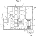
- FIG. 2 is a cross-sectional view of the substrate processing apparatus 1 according to the embodiments of the present disclosure when viewed from the side.
- FIGS. 1 and 2 illustrate the vertical substrate processing apparatus 1 as an example of the substrate processing apparatus.
- a substrate that is processed in the substrate processing apparatus 1 is illustrated as an example of a semiconductor wafer made of silicon or the like.
- the substrate processing apparatus 1 includes a housing 2, and a front maintenance port 4, as an opening configured to allow maintenance, is formed at a lower portion of a front wall 3 of the housing 2.
- the front maintenance port 4 is opened and closed by a front maintenance door 5.
- a pod loading/unloading port 6 is formed in the front wall 3 of the housing 2 to bring an inside and an outside of the housing 2 into fluid communication with each other.
- the pod loading/unloading port 6 is opened and closed by a front shutter 7, which is a loading/unloading port opening/closing mechanism.
- a load port 8, which is a substrate transfer container delivery stand, is installed at a front side of the pod loading/unloading port 6.
- the load port 8 is configured to align a pod 9 loaded thereon.
- the pod 9 is a sealed substrate transfer container, and is loaded onto and unloaded from the load port 8 by an in-process transfer apparatus (not illustrated).
- a rotary pod shelf 11 which is a substrate transfer container storage shelf, is installed at an upper region inside the housing 2 at the approximately center in the front-to-back direction.
- the rotary pod shelf 11 is configured to store a plurality of pods 9.
- the rotary pod shelf 11 includes a pillar 12, which is vertically erected and intermittently rotates, and shelf plates 13, which are multi-stage substrate transfer container mounting shelves, supported radially by the pillar 12 at upper, middle, and lower positions, respectively.
- Each of the shelf plates 13 is configured to store at least one pod 9 loaded thereon.
- a pod opener 14 which is a substrate transfer container lid opening/closing mechanism, is provided below the rotary pod shelf 11.
- the pod opener 14 is configured to be capable of mounting the pod 9 thereon and opening and closing the lid of the pod 9.
- the pod transfer mechanism 15 is configured to be capable of vertically moving and horizontally being retracted while holding the pod 9.
- the pod transfer mechanism 15 is configured to transfer the pod 9 among the load port 8, the rotary pod shelf 11, and the pod opener 14.
- a sub-housing 16 is provided at a lower portion approximately at a center in the front-to-back direction in the housing 2 so as to extend over the rear end.
- a pair of wafer loading/unloading ports 19, which are substrate loading/unloading ports for loading and unloading a wafer 18, which is a substrate, into and out of the sub-housing 16, are formed at a front wall 17 of the sub-housing 16 and are vertically arranged at two stages of an upper stage and a lower stage.
- the pod opener 14 is installed for each of upper and lower wafer loading/unloading ports 19.
- the pod opener 14 includes a mounting stand 21 on which the pod 9 is mounted and an opening/closing mechanism 22 for opening and closing the lid of the pod 9.
- the pod opener 14 is configured to open and close a wafer entrance of the pod 9 by opening and closing the lid of the pod 9 mounted on the mounting stand 21 using the opening/closing mechanism 22.
- the sub-housing 16 constitutes a transfer chamber 23, which is kept airtight from a space (pod transfer space) where the pod transfer mechanism 15 and the rotary pod shelf 11 are arranged.
- a wafer transfer mechanism 24, which is a substrate transfer mechanism, is installed in a front region of the transfer chamber 23.
- the wafer transfer mechanism 24 includes a pluarlity (e.g., five in the illustration) of wafer mounting plates 25 for mounting the wafer 18 thereon.
- the wafer mounting plates 25 are configured to be movable linearly in the horizontal direction, to be rotatable in the horizontal direction, or to be movable vertically.
- the wafer transfer mechanism 24 is configured to charge and discharge the wafer 18 into and out of a boat 26, which is a substrate holder.
- a standby part 27 configured to accommodate and keep the boat 26 in a standby state is formed in a rear region of the transfer chamber 23, and a vertical process furnace 28 is provided above the standby part 27.
- a process chamber 29 is formed inside the process furnace 28, and a lower end of the process chamber 29 is formed as a furnace opening.
- the furnace opening is configured to be opened and closed by a furnace opening shutter 31, which is a furnace opening/closing mechanism.
- the process chamber 29 is an example of a process container.
- a boat elevator 32 which is a substrate holder elevator, configured to raise or lower the boat 26 is installed between a right end of the housing 2 and a right end of the standby part 27 of the sub-housing 16.
- a seal cap 34 which serves as a lid, is installed horizontally to an arm 33 connected to an elevating stand of the boat elevator 32. The seal cap 34 is configured to vertically support the boat 26 and to airtightly close the furnace opening when the boat 26 is charged into the process chamber 29.
- the boat 26 is configured to hold a plurality of (e.g., about 50 to 125) wafers 18 in such a state that the wafers are arranged in a horizontal posture and in multiple stages with centers of the wafers aligned with one another.
- a notation of a numerical range such as "50 to 125” means that a lower limit value and an upper limit value are included in that range.
- "50 to 125” means "50 wafers or more and 125 wafers or less.” The same is applied to other numerical ranges.
- a cleaner 35 is arranged at a position facing the boat elevator 32.
- the cleaner 35 is composed of a supply fan and a dust filter to supply clean air 36, which is a purified atmosphere or inert gas.
- a nitrogen (N)-containing gas may be used as the inert gas.
- N-containing gas for example, a nitrogen (N 2 ) gas, ammonia (NH 3 ) gas or the like may be used. One or more of these may be used as the N-containing gas.
- a notch aligner (not illustrated), which serves as a substrate aligner for aligning locations of the wafer 18 in a circumferential direction thereof, is installed between the wafer transfer mechanism 24 and the cleaner 35.
- the clean air 36 blown out from the cleaner 35 circulates through the notch aligner (not illustrated), the wafer transfer mechanism 24, and the boat 26, and is then sucked into a duct (not illustrated), and is discharged to the outside of the housing 2 or blown into the transfer chamber 23 by the cleaner 35.
- the pod loading/unloading port 6 When the pod 9 is supplied to the load port 8, the pod loading/unloading port 6 is opened by the front shutter 7.
- the pod 9 on the load port 8 is loaded to the interior of the housing 2 through the pod loading/unloading port 6 by the pod transfer mechanism 15, and is mounted on the designated shelf plate 13 of the rotary pod shelf 11.
- the pod 9 After being temporarily stored on the rotary pod shelf 11, the pod 9 is transferred from the shelf plate 13 to one of the pod openers 14 and is transferred to the mounting stand 21 or transferred directly from the load port 8 to the mounting stand 21 by the pod transfer mechanism 15.
- each wafer loading/unloading port 19 is closed by the opening/closing mechanism 22, and the transfer chamber 23 is filled with the circulated clean air 36 flowing therethrough.
- the transfer chamber 23 is filled with the N-containing gas as the clean air 36, so that a concentration of oxygen is set to, for example, 20 ppm or less, which is lower than a concentration of oxygen in the interior (atmospheric atmosphere) of the housing 2.
- An end surface at an opening side of the pod 9 mounted on the mounting stand 21 is pressed against an opening edge of the wafer loading/unloading port 19 in the front wall 17 of the sub-housing 16, and the lid of the pod 9 is removed by the opening/closing mechanism 22 to open the wafer entrance.
- the wafer 18 When the pod 9 is opened by the pod opener 14, the wafer 18 is discharged from the pod 9 by the wafer transfer mechanism 24, and is then transferred to the notch aligner (not illustrated). After the wafer 18 is aligned by the notch aligner, the wafer transfer mechanism 24 loads the wafer 18 to the standby part 27 located at a rear region of the transfer chamber 23 and charges the wafer 18 into the boat 26.
- the wafer transfer mechanism 24 After delivering the wafer 18 to the boat 26, the wafer transfer mechanism 24 returns to the pod 9 and charges the next wafer 18 into the boat 26.
- the wafer transfer mechanism 24 While the wafer transfer mechanism 24 is charging the wafer 18 from one (upper or lower) pod opener 14 into the boat 26, another pod 9 is transferred from the rotary pod shelf 11 to the other (lower or upper) pod opener 14 by the pod transfer mechanism 15. Simultaneously, the pod 9 is opened by the pod opener 14 at the other side.
- the furnace opening of the process furnace 28, which was closed by the furnace opening shutter 31, is opened by the furnace opening shutter 31. Subsequently, the boat 26 is raised by the boat elevator 32 and is loaded into the process chamber 29.
- a purge step is performed in which the atmosphere inside the process chamber 29 is replaced with an inert gas.
- the process chamber 29 is vacuum-exhausted by a gas exhaust mechanism (not illustrated) to reach a desired pressure (vacuum degree). Further, the process chamber 29 is heated to a predetermined temperature by a heater driver (not illustrated) to achieve desired temperature distribution.
- a process gas controlled at a predetermined flow rate is supplied by a gas supplier (not illustrated).
- the process gas comes into contact with a surface of the wafer 18, and a predetermined process is performed on the surface of the wafer 18.
- the process gas after the reaction is discharged from the process chamber 29 by the gas exhaust mechanism.
- process gas herein refers to a gas supplied into the process chamber 29. The same applies to the following description.
- process time refers to a time during which the process is continued. The same applies to the following description.
- the wafer 18 and the pod 9 are unloaded to the outside of the housing 2 in the reverse procedure of the above-described procedure. Unprocessed wafers 18 are also charged into boat 26, and a batch process of the wafers 18 is repeated.
- the substrate processing apparatus 1 includes a control apparatus 100, and the control apparatus 100 controls the substrate processing apparatus 1.
- the control apparatus 100 may be built into the substrate processing apparatus 1, or may be provided in an accessible manner outside the substrate processing apparatus 1.
- the substrate processing apparatus 1 is an example of a target apparatus. In the following, a case where the control apparatus 100 according to the embodiments of the present disclosure is applied to the substrate processing apparatus 1 will be described, but the control apparatus 100 may control apparatuses other than the substrate processing apparatus 1.
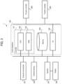
- FIG. 3 is a block diagram illustrating an example of a functional configuration of the control apparatus 100 included in the substrate processing apparatus 1 according to the embodiments of the present disclosure.
- the substrate processing apparatus 1 includes the control apparatus 100 as a main controller, an external communicator 201, an external memory 202, an operator 203, a display 204, a process controller 205, and a transfer controller 206.
- control apparatus 100 includes a controller 101, a memory 104, and an I/O (also referred to as "I/O port") 105.
- the controller 101 includes a central processing unit (CPU) 102 and a random access memory (RAM) 103.
- the control apparatus 100 is connected to the operator 203 and is also connected to the process controller 205 and the transfer controller 206 via the I/O 105. Since the control apparatus 100 is electrically connected to each of the process controller 205 and the transfer controller 206 via the I/O 105, it is configured to be capable of transmitting and receiving respective data or uploading and downloading respective files.
- the control apparatus 100 is connected to an external host computer (not illustrated) via the external communicator 201. Therefore, even in a case where the substrate processing apparatus 1 is installed in a clean room, it is possible to install the host computer in an office outside the clean room. Further, the control apparatus 100 is connected to the external memory 202, which serves as a mount into which a universal serial bus (USB) memory, as an example of a recording medium, is removably inserted.
- USB universal serial bus
- the operator 203 is integrated with the display 204, or is connected to the display 204 via, for example, a video cable.
- the display 204 is, for example, a liquid crystal display panel.
- the display 204 is configured to display each operation screen for operating the substrate processing apparatus 1.
- the operation screen includes a screen for monitoring a status of a substrate process system controlled by the process controller 205 and a substrate transfer system controlled by the transfer controller 206.
- the display 204 may be provided with each operation button as an input unit to input operational instructions of the substrate process system and the substrate transfer system.
- the operator 203 causes the display 204 to display information generated in the substrate processing apparatus 1 through the operation screen.
- the operator 203 causes information displayed on the display 204 to be outputted to a device such as a USB memory inserted into the external memory 202.
- the operator 203 receives input data (input instructions) from the operation screen displayed on the display 204, and transmits the input data to the control apparatus 100.
- the operator 203 receives instructions (control instructions) to execute an arbitrary substrate process recipe (also referred to as a "process recipe") among a plurality of recipes developed in the RAM 103 or stored in the memory 104, and transmits the instructions to the control apparatus 100.
- the operator 203 and the display 204 may be configured with a touch panel.
- the operator 203 and the display 204 are provided separately from the control apparatus 100 in the illustrated example, but may be integrally included in the control apparatus 100.
- the process controller 205 includes a temperature controller, a gas flow-rate controller, and a pressure controller.
- Each of the temperature controller, the gas flow-rate controller, and the pressure controller constitutes a sub-controller and is electrically connected to the process controller 205, so that it is configured to be capable of transmitting and receiving various data, downloading and uploading various files, and the like.
- the process controller 205 and each sub-controller are configured separately, but may be integrally configured.
- the transfer controller 206 although not illustrated here, includes a mechanism controller. This mechanism controller is configured to control each of a driver system, a rotator system, and an elevator system of the substrate processing apparatus 1.
- the transfer controller 206 is configured to control, for example, a transfer operation of each of the rotary pod shelf 11, boat elevator 32, pod transfer mechanism 15, wafer transfer mechanism 24, boat 26, and rotation mechanism (not illustrated).
- control apparatus 100 process controller 205, and transfer controller 206 according to the embodiments of the present disclosure are not limited to a dedicated system and may be realized using a conventional computer system.
- each controller that executes a predetermined process may be configured by installing a program for executing the above-described process from a recording medium (such as CD-ROM or USB) storing that program to a general-purpose computer.
- the program may be supplied via a predetermined recording medium as described above, or alternatively, may be supplied to the memory 104 via, for example, communication lines, communication networks, communication systems, etc.
- the control apparatus 100 is constituted as a computer including the CPU 102, RAM 103, memory 104, and I/O 105.
- the memory 104 stores recipe files such as recipes in which process conditions and process procedures are defined, a control program file for executing each recipe file, a parameter file (setting value file) for setting the process conditions and process procedures, an error-processing program file, an error-processing parameter file, a file of various screens including an input screen for inputting process parameters, a file of various icons, etc. (none of which are illustrated).
- the control apparatus 100 is connected to a network such as the Internet, local area network (LAN), or wide area network (WAN) using the external communicator 201, and is capable of communicating with external devices via the network.
- LAN local area network
- WAN wide area network
- the memory 104 stores an event occurrence notification processing program for executing an event occurrence notification process according to the embodiments of the present disclosure.
- the event occurrence notification processing program may be installed in advance in the substrate processing apparatus 1, for example.
- the event occurrence notification processing program may be realized by being recorded on a non-volatile recording medium, or distributed via a network, and appropriately installed in the substrate processing apparatus 1.
- examples of the non-volatile recording medium may include a CD-ROM, magneto-optical disk, HDD, DVD-ROM, flash memory, memory card, USB, and the like.
- the event occurrence notification processing program is a program that causes a computer to execute a process including: storing at least one event item indicating an event related to the substrate processing apparatus 1, which is an example of a target apparatus, in the memory 104; notifying the display 204 of an event item corresponding to an occurred event when the event item corresponding to the occurred event is stored in the memory 104; displaying the notified event item on the display 204; and controlling the processing of a substrate (e.g., wafer 18) based on an occurrence status of the event.
- a substrate e.g., wafer 18
- the CPU 102 of the substrate processing apparatus 1 functions as the controller 101 by writing the event occurrence notification processing program stored in the memory 104 into the RAM 103 and executing the event occurrence notification processing program.
- the substrate processing apparatus 1 includes the controller 101, the memory 104, and the display 204.
- the memory 104 stores at least one event item indicating an event related to the substrate processing apparatus 1.
- the event item includes, for example, at least one selected from the group of a recovery standby of an alarm occurred in a self-operating apparatus, a condition standby for executing a recipe, a recovery standby due to substrate crack detection, a condition standby for continuing substrate processing including a recipe, and installation standby of an update program.
- the event item at least one of the following items is stored in the memory 104. Addition, deletion, modification and the like are possible for event items stored in the memory 104.
- event items may be different according to a type of apparatus and conditions.
- the memory 104 By storing various event items in the memory 104, it is possible to cope with various apparatus-specific event items.
- the controller 101 When an event item corresponding to an occurred event is stored in the memory 104, it is possible for the controller 101 to perform a control of notifying the display 204 of the event item corresponding to the occurred event.
- an event item which is a display target, is stored in advance in the memory 104, as described above.
- the event item is not limited to being stored in the memory 104, but may be acquired by accessing an external recording medium such as a USB memory, CD, or DVD via the external memory 202. Further, the event item may be acquired by accessing an external device via the external communicator 201.
- the controller 101 notifies the display 204 of the event item corresponding to that event, and in other words, notifies of event occurrence.
- the display 204 collectively displays a plurality of events that occur in the substrate processing apparatus 1 upon receiving a notification from the controller 101. In addition, one event may be displayed. This makes it easy to confirm the events occurring in the substrate processing apparatus 1.
- controller 101 may control substrate processing based on an occurrence status of an event. For example, the controller 101 may control whether to continue substrate processing based on an event item indicating an event that is occurring.
- the processing of a substrate is performed, for example, based on a recipe that defines process conditions for the substrate.
- the recipe is stored in the memory 104, and the controller 101 acquires the stored recipe during the substrate processing and controls the substrate processing based on the process conditions defined in the recipe.
- the recipe may be not only stored in the memory 104, but also read from a USB memory, CD, or DVD via the external memory 202. Further, the recipe may be acquired from an external device via the external communicator 201.
- FIG. 4 is a front view illustrating an example of an information display screen 40 according to the embodiments of the present disclosure.
- the display 204 displays, for example, the information display screen 40 illustrated in FIG. 4 under the control by the controller 101.
- the information display screen 40 is a screen that displays various information regarding the substrate processing apparatus 1.
- the information display screen 40 illustrated in FIG. 4 includes, for example, a title information display area 41, an apparatus information display area 42, and a navigation information display area 43.
- the title information display area 41 is a fixed display area.
- the title information display area 41 is composed of a group of buttons, which are not affected by information on occurring failures as well as a content displayed in the apparatus information display area 42.
- An event display button 44 for displaying an event item display screen to be described later is disposed in the title information display area 41.
- Displays such as, for example, a self-operating apparatus status display, edition of a file such as a recipe or the like, a detailed display of failure information and the like, are switched in the apparatus information display area 42 according to an instruction selected in the navigation information display area 43.
- the navigation information display area 43 includes a group of buttons for selecting a type of a screen to be displayed in the apparatus information display area 42.
- FIG. 5A is a front view illustrating an example of an event item display screen 45 according to the embodiments of the present disclosure.
- the display 204 displays, for example, the event item display screen 45 illustrated in FIG. 5A in response to an operation of pressing the event display button 44 or the like.
- the event display button 44 is disposed in the title information display area 41 and becomes a validity when an event occurs currently but becomes an invalidity when no event occurs currently.
- the "validity” represents a case where it is possible to press the button and the "invalidity” represents a case where it is impossible to press the button.
- a case where the button is displayed represents the "validity” and a case where the button is not displayed represents the "invalidity.”
- the title information display area 41 is always displayed and is not hidden in other screens.
- the event item display screen 45 illustrated in FIG. 5A is a scree independent from the information display screen 40 illustrated in FIG. 4 as described above.
- the display 204 displays the event item display screen 45 on the top.
- the event item display screen 45 is displayed, for example, below the event display button 44 and is always displayed on the top. Therefore, even when the screen in the apparatus information display area 42 is switched, the event item display screen 45 is always displayed on the top.
- the apparatus information display area 42 and the event item display screen 45 are displayed in an overlapping manner.
- the event item display screen 45 and the information display screen 40 are displayed on different layers (levels), and each screen is displayed independently.
- the event item display screen 45 is disposed on an upper layer, and the information display screen 40 is disposed on a lower layer. Therefore, it is possible to display the event item display screen 45 always on the top rather than the information display screen 40.
- the event item display screen 45 is always displayed on the top even when the screen in the apparatus information display area 42 is switched, it is possible to grasp a currently occurring event although other tasks are performed. Further, it is possible to operate the screen on the lower layer than the event item display screen 45 regardless of the display of the event item display screen 45.
- the display 204 displays the event item display screen 45 immediately below the event display button 44 when the event display button 44 is operated.
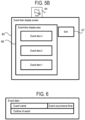
- the event items when responding to events in order in which the events occurred, the event items may be arranged in order of the occurrence of events. In other words, the event items may be arranged in order with the oldest event at the top and the currently occurring events below it. Further, the order of arrangement for the event items may be predefined by parameters. Alternatively, as illustrated in FIG. 5B , a sort button 47 for rearrangement may be provided on the event item display screen 45.
- the event occurrence count 44B may be set to non-display when the occurring event disappeared. Specifically, the event occurrence count 44B on the event display button 44 is set to non-display when no more events occur, that is, when the number of event occurrences is zero. However, the event occurrence count 44B may be displayed as "0.”
- the event item display screen 45 being displayed may be set to non-display in response to the operation of the event display button 44 or switching to another screen. Specifically, the display 204 temporarily maintains the display status (display or non-display) of the event item display screen 45 in the RAM 103. When the event display button 44 is operated, or when switched to another screen, the display status (display or non-display) of the event item display screen 45 is switched.
- the display 204 may disable the operation of the event display button 44 when no event occurred, or may not display the event item display screen 45 even though the event
- the event display button 44 is operated.
- the event display button 44 may be a state not to be pressed (e.g., grayed-out display, etc.) when no event occurred, that is, when the occurring event disappeared.
- the event item display screen 45 may not be displayed even though the event display button 44 is pressed.
- FIG. 8 is a front view illustrating an example of an event response screen 50 according to the embodiments of the present disclosure.
- the memory 104 further stores information indicating the event response screen 50 (event response screen information) which performs a response to an event. Addition, deletion, modification, and the like may be possible as the event response screen information stored in the memory 104.
- the display 204 displays, for example, the event response screen 50 corresponding to an event of the selected event item, as illustrated in FIG. 8 .
- the event response screen 50 is displayed by switching from the apparatus information display area 42, and the event item display screen 45 is erased.
- the event response screen 50 may be acquired through a recording medium such as USB memory, CD, or DVD, or an external device, similar to the event items. For example, when the event item is failure information, the event response screen 50 displays a list of failure information or a detailed failure information screen. When the event item is operation continuation standby, the event response screen 50 displays a system command screen. When the event item is crack detection, the event response screen 50 displays a crack detection recovery screen. When the event item is recipe execution standby, the event response screen 50 displays a recipe execution standby factor confirmation screen. When the event item is update program installation standby, the event response screen 50 displays a program installation screen.
- a recording medium such as USB memory, CD, or DVD, or an external device, similar to the event items.
- the event response screen 50 displays a list of failure information or a detailed failure information screen.
- the event item is operation continuation standby
- the event response screen 50 displays a system command screen.
- the event response screen 50 displays a crack detection recovery screen.
- the event response screen 50 displays
- FIG. 9 is a diagram illustrating an example of event item display information 60 according to the present embodiment.
- the occurred event is added to the event item display information 60 illustrated in FIG. 9 in an occurrence order.
- the event items and event response screen information are stored in the memory 104.
- the event items and event response screen information related to the occurred events are read from the memory 104 to the RAM 103.
- the event item display information 60 is made by associating the event occurrence time related to the occurred event with the number of event occurrences at the current time.
- the display 204 acquires the number of event occurrences from the event item display information 60, and displays, as the event occurrence count 44B, the acquired number of event occurrences on the event display button 44. Further, the display 204 rearranges the event items acquired from the event item display information 60 based on the event occurrence time and displays the even items on the event item display screen 45.
- FIG. 10 is a flowchart illustrating an example of a flow of an event occurrence notification process according to the embodiments of the present disclosure.
- step S 101 of FIG. 10 the controller 101 recognizes an occurrence of an event.
- the recognition of the event occurrence includes, for example, the recognition of a failure, substrate processing, and the like, by a notification from the I/O 105, the recognition of a failure, program update, and the like by a notification from the external communicator 201, and the recognition of program update, and the like by information from the external memory 202.
- step S102 the controller 101 determines whether or not an event item corresponding to the event recognized in step S101 is stored in the memory 104. If it is determined that the event item is stored in the memory 104 (in case of positive determination), the process proceeds to step S 103. If it is determined that the event item is not stored in the memory 104 (in case of negative determination), the event occurrence notification process is terminated.
- step S103 the controller 101 acquires the event item corresponding to the occurred event from the memory 104, and, as an example, stores this event item in the RAM 103 as the event item display information 60 illustrated in FIG. 9 as described above.
- step S104 as an example, the controller 101 updates the number of event occurrences in the event item display information 60 illustrated in FIG. 9 as described above.
- step S105 if the event item corresponding to the occurred event is stored in the memory 104, the controller 101 notifies the display 204 of the event item corresponding to the occurred event, and terminates the event occurrence notification process.
- the display 204 displays the event item display screen 45 according to the operation of the event display button 44 illustrated in FIG. 5A as described above.
- control apparatus and the substrate processing apparatus have been described by way of example.
- the embodiments may refer to a program for causing a computer to execute the functions of the control apparatus and the substrate processing apparatus.
- the embodiments may also refer to a non-transitory recording medium readable by a computer storing such a program.
- control apparatus and the substrate processing apparatus described in the above embodiments are given by way of example, and may be modified according to situations within the scope without departing from the gist.
- an example of performing a predetermined process on the substrate surface using a batch-type substrate processing apparatus that processes a plurality of substrates at once has been described.
- the present disclosure is not limited to the above-described aspect, and for example, may be suitably applied to a case where a predetermined process is performed on the substrate surface using a single-wafer type substrate processing apparatus that processes one or several substrates at once.
- an example of performing a predetermined process on the substrate surface using a substrate processing apparatus with a hot wall type process furnace has been described.
- the present disclosure is not limited to the above-described aspect and may be suitably applied to a case where a predetermined process is performed on the substrate surface using a substrate processing apparatus with a cold wall type processing furnace as well.
Landscapes
- Engineering & Computer Science (AREA)
- Automation & Control Theory (AREA)
- Physics & Mathematics (AREA)
- General Physics & Mathematics (AREA)
- Human Computer Interaction (AREA)
- General Engineering & Computer Science (AREA)
- Manufacturing & Machinery (AREA)
- Quality & Reliability (AREA)
- Container, Conveyance, Adherence, Positioning, Of Wafer (AREA)
- Testing And Monitoring For Control Systems (AREA)
- General Factory Administration (AREA)
Applications Claiming Priority (1)
| Application Number | Priority Date | Filing Date | Title |
|---|---|---|---|
| JP2023048169A JP2024136876A (ja) | 2023-03-24 | 2023-03-24 | 制御装置、基板処理装置、半導体装置の製造方法、及びプログラム |
Publications (1)
| Publication Number | Publication Date |
|---|---|
| EP4435545A1 true EP4435545A1 (de) | 2024-09-25 |
Family
ID=90363592
Family Applications (1)
| Application Number | Title | Priority Date | Filing Date |
|---|---|---|---|
| EP24161965.9A Pending EP4435545A1 (de) | 2023-03-24 | 2024-03-07 | Steuerungsvorrichtung, substratverarbeitungsvorrichtung, verfahren zur herstellung eines halbleiterbauelements und programm |
Country Status (6)
| Country | Link |
|---|---|
| US (1) | US20240321611A1 (de) |
| EP (1) | EP4435545A1 (de) |
| JP (1) | JP2024136876A (de) |
| KR (1) | KR20240143852A (de) |
| CN (1) | CN118692943A (de) |
| TW (1) | TWI882678B (de) |
Citations (1)
| Publication number | Priority date | Publication date | Assignee | Title |
|---|---|---|---|---|
| US20190035657A1 (en) * | 2016-03-31 | 2019-01-31 | Kokusai Electric Corporation | Substrate processing apparatus and device management controller |
Family Cites Families (3)
| Publication number | Priority date | Publication date | Assignee | Title |
|---|---|---|---|---|
| JP2008311461A (ja) | 2007-06-15 | 2008-12-25 | Hitachi Kokusai Electric Inc | 基板処理装置 |
| JP6789871B2 (ja) * | 2017-03-31 | 2020-11-25 | 株式会社荏原製作所 | 半導体製造装置の動作に関する表示を制御する方法を実行するプログラム、当該方法及び半導体製造装置の動作に関する表示を行うシステム |
| JP7082630B2 (ja) * | 2020-03-19 | 2022-06-08 | 株式会社Kokusai Electric | 基板処理装置、半導体装置の表示方法、半導体装置の製造方法、及びプログラム |
-
2023
- 2023-03-24 JP JP2023048169A patent/JP2024136876A/ja active Pending
-
2024
- 2024-02-05 TW TW113104457A patent/TWI882678B/zh active
- 2024-02-19 CN CN202410183943.6A patent/CN118692943A/zh active Pending
- 2024-03-07 EP EP24161965.9A patent/EP4435545A1/de active Pending
- 2024-03-07 KR KR1020240032485A patent/KR20240143852A/ko active Pending
- 2024-03-07 US US18/598,774 patent/US20240321611A1/en active Pending
Patent Citations (1)
| Publication number | Priority date | Publication date | Assignee | Title |
|---|---|---|---|---|
| US20190035657A1 (en) * | 2016-03-31 | 2019-01-31 | Kokusai Electric Corporation | Substrate processing apparatus and device management controller |
Also Published As
| Publication number | Publication date |
|---|---|
| JP2024136876A (ja) | 2024-10-04 |
| KR20240143852A (ko) | 2024-10-02 |
| US20240321611A1 (en) | 2024-09-26 |
| TWI882678B (zh) | 2025-05-01 |
| CN118692943A (zh) | 2024-09-24 |
| TW202441672A (zh) | 2024-10-16 |
Similar Documents
| Publication | Publication Date | Title |
|---|---|---|
| US9437465B2 (en) | Substrate processing apparatus and method of manufacturing semiconductor device | |
| JP5635270B2 (ja) | 基板処理装置及び基板処理システム及び基板処理装置の表示方法及び基板処理装置のパラメータ設定方法及び記録媒体 | |
| US12066815B2 (en) | Recipe creation method or apparatus utilizing a series of steps according to a target recipe file for semiconductor manufacturing or substrating processing | |
| KR101075128B1 (ko) | 기판 처리 장치 | |
| EP4435545A1 (de) | Steuerungsvorrichtung, substratverarbeitungsvorrichtung, verfahren zur herstellung eines halbleiterbauelements und programm | |
| US20080229386A1 (en) | Substrate processing apparatus | |
| JP4486692B2 (ja) | 基板処理装置 | |
| JP6689959B2 (ja) | 基板処理装置、処理システム及び半導体装置の製造方法 | |
| US20240338015A1 (en) | Controlling apparatus, substrate processing apparatus, method of manufacturing semiconductor device, and recording medium | |
| JP7224482B2 (ja) | システム、基板処理装置及びプログラム | |
| JP5374123B2 (ja) | 基板処理システム | |
| JP5546195B2 (ja) | 基板処理装置、基板処理装置の表示方法及び半導体装置の製造方法 | |
| EP4213190A1 (de) | Substratverarbeitungsvorrichtung, umschaltverfahren, verfahren zur herstellung eines halbleiterbauelements und programm | |
| TWI917900B (zh) | 控制裝置、基板處理裝置、處理方法、半導體裝置之製造方法及程式 | |
| JP2014056403A (ja) | 基板処理装置 | |
| US20250079210A1 (en) | Display processing apparatus, substrate processing apparatus, display method, substrate processing method, method of manufacturing semiconductor device and non-transitory computer-readable recording medium | |
| JP2024044002A (ja) | 基板処理装置、半導体装置の製造方法、及びプログラム | |
| JP2025151167A (ja) | シミュレータ装置、基板処理装置、半導体装置の製造方法、およびプログラム | |
| JP2013102037A (ja) | 基板処理装置 |
Legal Events
| Date | Code | Title | Description |
|---|---|---|---|
| PUAI | Public reference made under article 153(3) epc to a published international application that has entered the european phase |
Free format text: ORIGINAL CODE: 0009012 |
|
| STAA | Information on the status of an ep patent application or granted ep patent |
Free format text: STATUS: REQUEST FOR EXAMINATION WAS MADE |
|
| 17P | Request for examination filed |
Effective date: 20240307 |
|
| AK | Designated contracting states |
Kind code of ref document: A1 Designated state(s): AL AT BE BG CH CY CZ DE DK EE ES FI FR GB GR HR HU IE IS IT LI LT LU LV MC ME MK MT NL NO PL PT RO RS SE SI SK SM TR |
|
| P01 | Opt-out of the competence of the unified patent court (upc) registered |
Free format text: CASE NUMBER: APP_25440/2025 Effective date: 20250528 |