EP4582693A1 - Packaged gas compressor - Google Patents
Packaged gas compressor Download PDFInfo
- Publication number
- EP4582693A1 EP4582693A1 EP23859739.7A EP23859739A EP4582693A1 EP 4582693 A1 EP4582693 A1 EP 4582693A1 EP 23859739 A EP23859739 A EP 23859739A EP 4582693 A1 EP4582693 A1 EP 4582693A1
- Authority
- EP
- European Patent Office
- Prior art keywords
- enclosure
- cooling fan
- cooling
- compressor body
- rotation axis
- Prior art date
- Legal status (The legal status is an assumption and is not a legal conclusion. Google has not performed a legal analysis and makes no representation as to the accuracy of the status listed.)
- Pending
Links
Images


Classifications
-
- F—MECHANICAL ENGINEERING; LIGHTING; HEATING; WEAPONS; BLASTING
- F04—POSITIVE - DISPLACEMENT MACHINES FOR LIQUIDS; PUMPS FOR LIQUIDS OR ELASTIC FLUIDS
- F04B—POSITIVE-DISPLACEMENT MACHINES FOR LIQUIDS; PUMPS
- F04B39/00—Component parts, details, or accessories, of pumps or pumping systems specially adapted for elastic fluids, not otherwise provided for in, or of interest apart from, groups F04B25/00 - F04B37/00
- F04B39/06—Cooling; Heating; Prevention of freezing
- F04B39/066—Cooling by ventilation
-
- F—MECHANICAL ENGINEERING; LIGHTING; HEATING; WEAPONS; BLASTING
- F01—MACHINES OR ENGINES IN GENERAL; ENGINE PLANTS IN GENERAL; STEAM ENGINES
- F01C—ROTARY-PISTON OR OSCILLATING-PISTON MACHINES OR ENGINES
- F01C21/00—Component parts, details or accessories not provided for in groups F01C1/00 - F01C20/00
- F01C21/007—General arrangements of parts; Frames and supporting elements
-
- F—MECHANICAL ENGINEERING; LIGHTING; HEATING; WEAPONS; BLASTING
- F04—POSITIVE - DISPLACEMENT MACHINES FOR LIQUIDS; PUMPS FOR LIQUIDS OR ELASTIC FLUIDS
- F04B—POSITIVE-DISPLACEMENT MACHINES FOR LIQUIDS; PUMPS
- F04B39/00—Component parts, details, or accessories, of pumps or pumping systems specially adapted for elastic fluids, not otherwise provided for in, or of interest apart from, groups F04B25/00 - F04B37/00
- F04B39/12—Casings; Cylinders; Cylinder heads; Fluid connections
- F04B39/121—Casings
-
- F—MECHANICAL ENGINEERING; LIGHTING; HEATING; WEAPONS; BLASTING
- F04—POSITIVE - DISPLACEMENT MACHINES FOR LIQUIDS; PUMPS FOR LIQUIDS OR ELASTIC FLUIDS
- F04B—POSITIVE-DISPLACEMENT MACHINES FOR LIQUIDS; PUMPS
- F04B39/00—Component parts, details, or accessories, of pumps or pumping systems specially adapted for elastic fluids, not otherwise provided for in, or of interest apart from, groups F04B25/00 - F04B37/00
- F04B39/12—Casings; Cylinders; Cylinder heads; Fluid connections
- F04B39/123—Fluid connections
-
- F—MECHANICAL ENGINEERING; LIGHTING; HEATING; WEAPONS; BLASTING
- F04—POSITIVE - DISPLACEMENT MACHINES FOR LIQUIDS; PUMPS FOR LIQUIDS OR ELASTIC FLUIDS
- F04C—ROTARY-PISTON, OR OSCILLATING-PISTON, POSITIVE-DISPLACEMENT MACHINES FOR LIQUIDS; ROTARY-PISTON, OR OSCILLATING-PISTON, POSITIVE-DISPLACEMENT PUMPS
- F04C18/00—Rotary-piston pumps specially adapted for elastic fluids
- F04C18/08—Rotary-piston pumps specially adapted for elastic fluids of intermeshing-engagement type, i.e. with engagement of co-operating members similar to that of toothed gearing
- F04C18/12—Rotary-piston pumps specially adapted for elastic fluids of intermeshing-engagement type, i.e. with engagement of co-operating members similar to that of toothed gearing of other than internal-axis type
- F04C18/14—Rotary-piston pumps specially adapted for elastic fluids of intermeshing-engagement type, i.e. with engagement of co-operating members similar to that of toothed gearing of other than internal-axis type with toothed rotary pistons
- F04C18/16—Rotary-piston pumps specially adapted for elastic fluids of intermeshing-engagement type, i.e. with engagement of co-operating members similar to that of toothed gearing of other than internal-axis type with toothed rotary pistons with helical teeth, e.g. chevron-shaped, screw type
-
- F—MECHANICAL ENGINEERING; LIGHTING; HEATING; WEAPONS; BLASTING
- F04—POSITIVE - DISPLACEMENT MACHINES FOR LIQUIDS; PUMPS FOR LIQUIDS OR ELASTIC FLUIDS
- F04C—ROTARY-PISTON, OR OSCILLATING-PISTON, POSITIVE-DISPLACEMENT MACHINES FOR LIQUIDS; ROTARY-PISTON, OR OSCILLATING-PISTON, POSITIVE-DISPLACEMENT PUMPS
- F04C29/00—Component parts, details or accessories of pumps or pumping installations, not provided for in groups F04C18/00 - F04C28/00
- F04C29/04—Heating; Cooling; Heat insulation
-
- F—MECHANICAL ENGINEERING; LIGHTING; HEATING; WEAPONS; BLASTING
- F04—POSITIVE - DISPLACEMENT MACHINES FOR LIQUIDS; PUMPS FOR LIQUIDS OR ELASTIC FLUIDS
- F04C—ROTARY-PISTON, OR OSCILLATING-PISTON, POSITIVE-DISPLACEMENT MACHINES FOR LIQUIDS; ROTARY-PISTON, OR OSCILLATING-PISTON, POSITIVE-DISPLACEMENT PUMPS
- F04C18/00—Rotary-piston pumps specially adapted for elastic fluids
- F04C18/02—Rotary-piston pumps specially adapted for elastic fluids of arcuate-engagement type, i.e. with circular translatory movement of co-operating members, each member having the same number of teeth or tooth-equivalents
- F04C18/0207—Rotary-piston pumps specially adapted for elastic fluids of arcuate-engagement type, i.e. with circular translatory movement of co-operating members, each member having the same number of teeth or tooth-equivalents both members having co-operating elements in spiral form
-
- F—MECHANICAL ENGINEERING; LIGHTING; HEATING; WEAPONS; BLASTING
- F04—POSITIVE - DISPLACEMENT MACHINES FOR LIQUIDS; PUMPS FOR LIQUIDS OR ELASTIC FLUIDS
- F04C—ROTARY-PISTON, OR OSCILLATING-PISTON, POSITIVE-DISPLACEMENT MACHINES FOR LIQUIDS; ROTARY-PISTON, OR OSCILLATING-PISTON, POSITIVE-DISPLACEMENT PUMPS
- F04C29/00—Component parts, details or accessories of pumps or pumping installations, not provided for in groups F04C18/00 - F04C28/00
- F04C29/06—Silencing
Definitions
- the present invention relates to a packaged gas compressor, and more specifically relates to a packaged gas compressor that air-cools components inside its package.
- the present invention has been made to solve the problem described above, and an object thereof is to provide a packaged gas compressor that can maintain the integrity of the cooling performance while noise being reduced.
- the heat exchanger is arranged at a position on a suction side of the cooling fan.
- the intake port is provided to overlap the compressor body in the height direction of the enclosure, and is provided at a position closer to the cooling fan than to the heat exchanger.
- the compressor body is arranged to overlap, in an extending direction of the rotation axis of the cooling fan, an area between the heat exchanger and a facing surface of the side surface of the enclosure, the facing surface facing an inlet side of the heat exchanger into which the cooling air flows.
- the cooling fan arranged above the compressor body is arranged such that the rotation axis is orthogonal to the height direction of the enclosure, the heat exchanger is arranged at a position on the suction side of the cooling fan, and the intake port is provided at the height of the compressor body and at a position closer to the cooling fan than to the heat exchanger.
- the compressor body so as to overlap the area between the heat exchanger and the side surface of the enclosure causes the compressor body to be positioned in an area where the cooling air is caused to turn around in the U-shape.
- the cooling performance for the compressor body can be enhanced more than that in the case of a configuration in which a cooling fan is arranged such that its rotation axis extends in the height direction of the enclosure and a heat exchanger is arranged downstream of the cooling fan. Accordingly, the integrity of the cooling performance can be maintained while noise being reduced by reducing the opening area of the intake port, or the like.
- a packaged gas compressor according to the present invention is illustratively explained using the figures.
- a screw-type compressor is explained as an example of a gas compressor.
- the present invention can be applied also to a scroll-type, reciprocating-type, or turbo-type compressor.
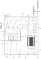
- FIG. 1 is a perspective view of the packaged gas compressor according to the first embodiment of the present invention as seen from the rear side.
- FIG. 2 is a rear view of the packaged gas compressor according to the first embodiment depicted in FIG. 1 .
- FIG. 3 is a top view of the packaged gas compressor according to the first embodiment depicted in FIG. 1 .
- FIG. 4 is a figure of a cooling fan and intake/exhaust ducts included as part of the packaged gas compressor according to the first embodiment depicted in FIG. 1 as seen from a side where a right side panel is present.
- a package and ducts are in a transparent state.
- FIG. 1 a package and ducts are in a transparent state.
- a rear side panel and the ducts are in a transparent state.
- a top panel is in a transparent state.
- an exhaust duct is in a transparent state. Note that, in this explanation, the left-right direction represents the left-right direction of the packaged gas compressor as seen from the front side.
- the packaged gas compressor houses various components including a compressor body 2 inside an enclosure 1 as the package.
- the components of the packaged gas compressor includes: the compressor body 2 that compresses a gas; a prime mover 3 that drives the compressor body 2; an air cooler 4 that cools a compressed gas (a fluid) discharged from the compressor body 2; an oil cooler 5 that cools a lubricant (a fluid) to be supplied to the compressor body 2; an oil tank 6 that temporarily stores the lubricant (the fluid) to be supplied to the compressor body 2; a cooling fan 7 that induces cooling air inside the enclosure 1; a starting panel 8 having a control circuit that controls driving of the prime mover 3 and the cooling fan 7; and the like.
- the compressor body 2 is a screw-type compressor including a screw rotor with twisted lobes, for example.
- the prime mover 3 is an electric motor that rotates around a rotation axis Am (see FIG. 2 and FIG. 3 ), for example.
- the air cooler 4 is an air-cooling-type heat exchanger that cools a compressed gas introduced from the compressor body 2 by passage of the cooling air, and has an inlet surface 4a through which the cooling air flows in.
- the oil cooler 5 is an air-cooling-type heat exchanger that cools a lubricant introduced from the compressor body 2 by passage of the cooling air, and has an inlet surface 5a through which the cooling air flows in.
- the cooling fan 7 is a centrifugal fan that rotates around a rotation axis Af (see FIG. 2 and FIG. 3 ), and contains therein a fan motor, for example.
- the enclosure 1 has: a base 11; a side panel with a tubular shape, which rises from the periphery of the base 11 and surrounds the components 2, 3, 4, 5, 6, 7, and 8; and a top panel 12 that closes the upper end opening of the side panel, for example.
- the base 11 is formed in a rectangular shape as seen from the upper side, for example.
- the side panel includes; a front side panel 13; a rear side panel 14 facing the front side panel 13; a left side panel 15 connected to a left end of the front side panel 13 and a left end of the rear side panel 14; and a right side panel 16 connected to a right end of the front side panel 13 and a right end of the rear side panel 14, for example.
- On the front side panel 13 are arranged an operation switch, a monitor, and the like which are not depicted.
- the compressor body 2 and the electric motor 3 are integrated such that their axial directions are parallel to each other to configure one body unit.
- the body unit 2 and 3 is arranged on the lower side in the enclosure 1, for example, on the base 11, as depicted in FIG. 1 and FIG. 2 .
- the body unit 2 and 3 is installed horizontally such that the axial direction of the compressor body 2 and the rotation axis Am of the electric motor 3 are approximately parallel to the installation surface of the base 11.
- the body unit 2 and 3 is arranged to extend in the left-right direction (the width direction of the enclosure 1) between the left side panel 15 and the right side panel 16, and arranged at a position closer to the rear side panel 14 than to the front side panel 13 in the enclosure 1 (on a side where the rear side panel 14 is present), as depicted in FIG. 1 and FIG. 3 .
- the body unit 2 and 3 is arranged such that the compressor body 2 is positioned on a side where the left side panel 15 is present and the electric motor 3 is positioned on a side where the right side panel 16 is present.
- the oil tank 6 and the starting panel 8 are arranged, for example.
- the oil tank 6 is arranged on a side where the left side panel 15 is present, so as to be adjacent to the compressor body 2, for example.
- the oil tank 6 is a container extending in the upper-lower direction, and is installed on the base 11, for example, as depicted in FIG. 1 and FIG. 2 .
- the starting panel 8 is installed on the base 11 and is arranged on a side where the right side panel 16 is present, so as to be adjacent to the electric motor 3 along the front side panel 13, for example, as depicted in FIG. 1 to FIG. 3 .
- the cooling fan 7, the air cooler 4, and the oil cooler 5 are arranged on the upper side in the enclosure 1, as depicted in FIG. 1 and FIG. 2 . That is, the cooling fan 7, the air cooler 4, and the oil cooler 5 are positioned above the body unit 2 and 3.
- the cooling fan 7 is arranged such that the rotation axis Af is orthogonal to the height direction of the enclosure 1 and is approximately parallel to the rotation axis Am of the electric motor 3 (the axial direction of the compressor body 2), as depicted in FIG. 1 to FIG. 3 . That is, the cooling fan 7 is arranged such that the rotation axis Af extends in the left-right direction (the width direction of the enclosure 1).
- the cooling fan 7 is arranged such that its position in the left-right direction (the width direction of the enclosure 1) overlaps part of the electric motor 3, and such that its suction side faces the compressor body 2 (the left side panel 15), for example.
- the air cooler 4 and the oil cooler 5 are arranged on the suction side of the cooling fan 7 (on the upstream side of the flow of cooling air).
- the air cooler 4 and the oil cooler 5 are connected to the cooling fan 7 via a fan intake duct 21.
- the fan intake duct 21 rectifies the flow of the cooling air from the air cooler 4 and the oil cooler 5 to the cooling fan 7.
- the air cooler 4 and the oil cooler 5 are each arranged such that the inlet surface 4a and the inlet surface 5a for the cooling air are orthogonal to the rotation axis Af of the cooling fan 7.
- the air cooler 4 and the oil cooler 5 are arranged side by side relative to the rotation axis Af of the cooling fan 7, and their inlet surfaces 4a and 5a form one inlet surface for the cooling air, for example.
- the cooling fan 7 is arranged in the exhaust duct 22 such that the rotation axis Af does not cross the centerline Cd of the exhaust duct 22, but is offset toward the front side panel 13, as depicted in FIG. 3 and FIG. 4 . That is, the cooling fan 7 is arranged in the exhaust duct such that the rotation axis Af is offset from the centerline Cd of the exhaust duct 22 toward an area where the rotation direction of the cooling fan 7 is a downward direction in the height direction of the enclosure as seen from one side of the extending direction of the rotation axis Af.
- FIG. 1 to FIG. 4 Next, operation and effects and advantages of the packaged gas compressor according to the first embodiment are explained using FIG. 1 to FIG. 4 .
- FIG. 2 broken-line arrows represent the flow of cooling air.
- FIG. 3 broken-line thick arrows represent the flow of cooling air.
Landscapes
- Engineering & Computer Science (AREA)
- Mechanical Engineering (AREA)
- General Engineering & Computer Science (AREA)
- Compressor (AREA)
- Applications Or Details Of Rotary Compressors (AREA)
- Compressors, Vaccum Pumps And Other Relevant Systems (AREA)
Applications Claiming Priority (2)
| Application Number | Priority Date | Filing Date | Title |
|---|---|---|---|
| JP2022137648A JP2024033811A (ja) | 2022-08-31 | 2022-08-31 | パッケージ型気体圧縮機 |
| PCT/JP2023/019183 WO2024047969A1 (ja) | 2022-08-31 | 2023-05-23 | パッケージ型気体圧縮機 |
Publications (1)
| Publication Number | Publication Date |
|---|---|
| EP4582693A1 true EP4582693A1 (en) | 2025-07-09 |
Family
ID=90099322
Family Applications (1)
| Application Number | Title | Priority Date | Filing Date |
|---|---|---|---|
| EP23859739.7A Pending EP4582693A1 (en) | 2022-08-31 | 2023-05-23 | Packaged gas compressor |
Country Status (4)
| Country | Link |
|---|---|
| EP (1) | EP4582693A1 (enExample) |
| JP (1) | JP2024033811A (enExample) |
| CN (1) | CN119768609A (enExample) |
| WO (1) | WO2024047969A1 (enExample) |
Family Cites Families (5)
| Publication number | Priority date | Publication date | Assignee | Title |
|---|---|---|---|---|
| JP2574819B2 (ja) * | 1987-11-18 | 1997-01-22 | 株式会社日立製作所 | パツケージ形圧縮装置 |
| JP4437434B2 (ja) * | 2004-10-14 | 2010-03-24 | 株式会社日立産機システム | スクロール空気圧縮機 |
| CN102679671B (zh) * | 2011-03-09 | 2014-10-15 | 株式会社电装 | 制冷循环单元 |
| JP2016089665A (ja) * | 2014-10-31 | 2016-05-23 | 株式会社Ihi | パッケージ形水潤滑式スクリュ圧縮機 |
| JP6518383B2 (ja) | 2016-05-09 | 2019-05-22 | 株式会社日立産機システム | パッケージ形圧縮機 |
-
2022
- 2022-08-31 JP JP2022137648A patent/JP2024033811A/ja active Pending
-
2023
- 2023-05-23 WO PCT/JP2023/019183 patent/WO2024047969A1/ja not_active Ceased
- 2023-05-23 EP EP23859739.7A patent/EP4582693A1/en active Pending
- 2023-05-23 CN CN202380061977.1A patent/CN119768609A/zh active Pending
Also Published As
| Publication number | Publication date |
|---|---|
| WO2024047969A1 (ja) | 2024-03-07 |
| CN119768609A (zh) | 2025-04-04 |
| JP2024033811A (ja) | 2024-03-13 |
Similar Documents
| Publication | Publication Date | Title |
|---|---|---|
| TWI703268B (zh) | 流體機械 | |
| US6210132B1 (en) | Partition means for directing air flow over a cooler in an oilless scroll compressor | |
| US11473582B2 (en) | Package-type compressor | |
| KR101583080B1 (ko) | 공기조화장치용 실외기 | |
| JP5899150B2 (ja) | パッケージ型流体機械 | |
| KR100310104B1 (ko) | 패키지형 스크롤 압축기 | |
| US10920779B2 (en) | Package-type air-cooled screw compressor having a cooling air exhaust opening in the package with a duct extended downward with a lower-end inlet placed not viewable from the center position of the compressor | |
| KR100837143B1 (ko) | 패키지형 압축기 | |
| CN111121359B (zh) | 冷却系统 | |
| JP2003035260A (ja) | 空気圧縮機 | |
| EP4582693A1 (en) | Packaged gas compressor | |
| JP6694094B2 (ja) | パッケージ形圧縮機 | |
| JP2005171957A (ja) | パッケージ型圧縮機 | |
| CN113518885A (zh) | 空调机用室外机以及空调机 | |
| JP4996142B2 (ja) | パッケージ形圧縮機 | |
| JP3974515B2 (ja) | エンジン作業機 | |
| JP5707280B2 (ja) | パッケージ型圧縮機。 | |
| JP7564226B2 (ja) | パッケージ形圧縮機 | |
| JP7399495B2 (ja) | パッケージ型回転ポンプユニット | |
| JP7019135B1 (ja) | パッケージ型回転ポンプユニット | |
| JP2024033811A5 (enExample) | ||
| JP7057609B1 (ja) | パッケージ型回転ポンプユニット | |
| KR101520495B1 (ko) | 공기조화장치용 실외기 | |
| WO2025004172A1 (ja) | 空調ユニット及び冷凍サイクル装置 | |
| CN112424921B (zh) | 冷冻机 |
Legal Events
| Date | Code | Title | Description |
|---|---|---|---|
| STAA | Information on the status of an ep patent application or granted ep patent |
Free format text: STATUS: THE INTERNATIONAL PUBLICATION HAS BEEN MADE |
|
| PUAI | Public reference made under article 153(3) epc to a published international application that has entered the european phase |
Free format text: ORIGINAL CODE: 0009012 |
|
| STAA | Information on the status of an ep patent application or granted ep patent |
Free format text: STATUS: REQUEST FOR EXAMINATION WAS MADE |
|
| 17P | Request for examination filed |
Effective date: 20250331 |
|
| AK | Designated contracting states |
Kind code of ref document: A1 Designated state(s): AL AT BE BG CH CY CZ DE DK EE ES FI FR GB GR HR HU IE IS IT LI LT LU LV MC ME MK MT NL NO PL PT RO RS SE SI SK SM TR |
|
| DAV | Request for validation of the european patent (deleted) | ||
| DAX | Request for extension of the european patent (deleted) |