EP4581933A2 - Paire d'éléments de déplacement - Google Patents
Paire d'éléments de déplacement Download PDFInfo
- Publication number
- EP4581933A2 EP4581933A2 EP25178827.9A EP25178827A EP4581933A2 EP 4581933 A2 EP4581933 A2 EP 4581933A2 EP 25178827 A EP25178827 A EP 25178827A EP 4581933 A2 EP4581933 A2 EP 4581933A2
- Authority
- EP
- European Patent Office
- Prior art keywords
- displacement
- wing
- elements
- displacement elements
- wing section
- Prior art date
- Legal status (The legal status is an assumption and is not a legal conclusion. Google has not performed a legal analysis and makes no representation as to the accuracy of the status listed.)
- Pending
Links
Images
Classifications
-
- A—HUMAN NECESSITIES
- A22—BUTCHERING; MEAT TREATMENT; PROCESSING POULTRY OR FISH
- A22C—PROCESSING MEAT, POULTRY, OR FISH
- A22C11/00—Sausage making ; Apparatus for handling or conveying sausage products during manufacture
- A22C11/12—Apparatus for tying sausage skins ; Clipping sausage skins
-
- A—HUMAN NECESSITIES
- A22—BUTCHERING; MEAT TREATMENT; PROCESSING POULTRY OR FISH
- A22C—PROCESSING MEAT, POULTRY, OR FISH
- A22C11/00—Sausage making ; Apparatus for handling or conveying sausage products during manufacture
- A22C11/006—Separating linked sausages
-
- A—HUMAN NECESSITIES
- A22—BUTCHERING; MEAT TREATMENT; PROCESSING POULTRY OR FISH
- A22C—PROCESSING MEAT, POULTRY, OR FISH
- A22C11/00—Sausage making ; Apparatus for handling or conveying sausage products during manufacture
- A22C11/10—Apparatus for twisting or linking sausages
- A22C11/104—Apparatus for twisting or linking sausages by means of shear or blade elements
-
- A—HUMAN NECESSITIES
- A22—BUTCHERING; MEAT TREATMENT; PROCESSING POULTRY OR FISH
- A22C—PROCESSING MEAT, POULTRY, OR FISH
- A22C11/00—Sausage making ; Apparatus for handling or conveying sausage products during manufacture
- A22C11/10—Apparatus for twisting or linking sausages
- A22C11/107—A string passing between two rotary members comprising dividing elements cooperating with each other
Definitions
- the invention relates to a pair of displacement elements and a device for dividing a sausage strand with such a pair of displacement elements according to the preamble of claims 1 and 7.
- a pasty mass is filled into a sausage casing, for example, via a filling tube, creating a filled sausage strand.
- so-called displacing elements are used to displace the pasty mass in the product strand at predetermined intervals, particularly to create a constriction.
- the sausage strand to be filled can be twisted around its longitudinal axis, for example, using a twisting unit, whereby a twisting point then occurs at the constriction point, thus dividing the sausage strand.
- folds form between the displacing elements during constriction.
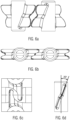
- Figure 6a shows a perspective view of two opposing displacement elements according to the prior art, which are rotated in opposite directions about their respective axes A.
- the sausage strand moves between the displacement elements.
- each displacement element has at least one vane with an upper vane section and a lower vane section, which, as shown in Figure 6b shown, interlock in a compartment position.
- the opposite upper wing sections and the opposite lower wing sections each run at an angle of, for example, 2 times 20 ° to each other.
- the present invention is based on the object of providing improved displacement elements for a device for dividing a sausage strand, which enable the dividing point to intervene quickly and gently.
- a pair of displacement elements is provided for dividing a sausage strand transported between the displacement elements into individual sausages.
- Each displacement element has at least one wing, which has a first wing section and a second wing section, between which an outwardly widening, in particular V-shaped, cutout is formed.
- Both the first, e.g., upper, and the second, e.g., lower, wing sections each have a laterally curved pocket or opening.
- the curved pocket or opening each located in an area within the outer contour of the respective wing section, allows the displacement elements to move past one another in such a way that the wing sections do not collide during rotation because, for example, a first wing section can move past the area of the curved pocket of the corresponding wing section of the opposite displacement element, i.e., can move through the free space created by the pocket or opening.
- the displacement edge i.e. the outer contour of the first and second wing sections of a respective displacement element, lies at least in the region of the widening cutout either a) in substantially parallel planes or b) in a common plane. If the displacement edges of the first and second wing sections lie in parallel planes, the wings can interlock in order to separate the sausage strand. If the displacement edges of the first and second wing sections lie in a common plane, the separation can be achieved by wings that are parallel to one another. The planes in particular each run accordingly through the center of the wing width in the region of the widening section.
- This arrangement makes it possible to keep the distance between the wings of the opposing displacement elements small in a sectioning position, at least in the area of the outwardly widening, particularly V-shaped, section.
- the distance can also be essentially constant.
- the wing sections do not diverge as in the prior art, effectively preventing the formation of wrinkles and twisting the sausage strand in a very short time during twisting, and the twisting point springs into place. The sectioning point is thus created more gently overall.
- the distance between the planes is preferably within the following range: the thickness of the wing sections + 0 mm to 4 mm, in particular the thickness + 0.1 mm to 3 mm, in particular + 0.2 mm to 1 mm. In this range, no jamming occurs, and the turning point snaps into place quickly and completely.
- the thickness, in particular the maximum thickness (if the thickness is not constant), of the wing sections in the expanding cutout is considered.
- the curved pocket in the first wing section of a respective displacement element is curved outwardly to a first side, and in the second wing section, the curved pocket is curved to the opposite side.
- the curved pockets in the first and second wing sections are curved to the same side.
- the wing of the first displacement element and the wing of the second opposite displacement element can interlock or the wings can be arranged substantially parallel to one another.
- the vanes can be arranged in a flag-like manner on a mount, via which they can be connected to a rotating mechanism, which in particular comprises a drive shaft, in order to rotate the displacement elements about an axis or to move them in rotation about multiple axes.
- a rotating mechanism which in particular comprises a drive shaft
- the displacement elements are either rotated at a distance from one another about, for example, their central axis, or are each mounted on a transport means, e.g., a chain or conveyor belt, etc., and rotate.
- the displacement elements of the invention even when rotated or circulated, offer the same advantages as linearly moving displacement elements, whose vanes can be arranged very close to each other in the compartment position.
- the rotational or circulating movement can increase the production speed.
- a device for dividing a sausage strand comprises at least one pair of displacement elements according to at least one of claims 1-6. Furthermore, the device comprises a transport device for transporting the filled sausage strand between the opposing displacement elements. Furthermore, the device comprises a rotation mechanism for rotating the displacement elements about a respective rotation axis or for rotating them about multiple rotation axes.
- the displacement elements can also displace the pasty mass without a twisting device
- a twisting device for rotating the sausage strand around its longitudinal axis L is advantageous so that a twisting point can be created between the individual sausages.
- no twisting device is necessary in coextruded sausages, in which a sausage casing is extruded together with the pasty mass.
- the present invention is advantageous because a well-formed separation point can be created without oblique squeezing.
- the displacement elements can be rotated about their central axis A1 via the rotation mechanism, with the central axis running essentially parallel to the planes E1, E2, in which the displacement edge of the wing sections lies at least in the region of the widening cutout.
- the central axis or rotation axis extends perpendicular to the transport direction T of the sausage strand.
- the opposing displacement elements are each arranged on two transport means rotating around multiple axes, in particular a transport chain or a conveyor belt.
- the axes of rotation are preferably substantially parallel to the planes in which the displacement edges of the first and second wing sections are arranged in the region of the particularly V-shaped cutout.
- the axes of rotation preferably run perpendicular to the transport direction of the sausage strand.
- a displacement element has several rotating vanes, or several displacement elements, each with a vane, are arranged on the respective rotating transport means. This allows the throughput to be increased.
- the displacement elements are manufactured using 3D printing or injection molding.
- 3D printing makes it particularly easy to manufacture a displacement element that features the pockets or recesses according to the invention.
- metal displacement elements can also be manufactured using 3D printing.
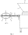
- a transport device 16 is shown only as an example, which has opposite, circulating transport means, e.g. conveyor belts or transport chains, etc., between which the filled sausage strand 11 is transported.
- the displacement elements 1a, 1b are arranged on the circulating transport means, e.g. the circulating conveyor belt, chain, etc., in particular at uniform intervals.
- the circulating transport means e.g. the circulating conveyor belt, chain, etc.
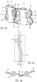
- FIG. 3 schematically shows a displacement element according to an embodiment of the invention.
- the displacement element has at least one wing 2a, with an upper, i.e., first, wing section 3a and a lower, i.e., second, wing section 4a. Between the two wing sections, an outwardly widening, in particular V-shaped, open-edge cutout 12 is provided. The displacement edges 13 are arranged in the region of the V-shaped cutout 12.
- the outward extension k of the lower and upper wing sections 3a, 4a is, for example, in a range from 30 mm to 80 mm.
- the thickness of the wings for example, ranges from 1 mm to 6 mm, preferably from 1 mm to 3 mm.
- Corresponding displacement elements are suitable for sausage calibers ranging from 8 mm to 60 mm.
- the invention also enables the use of the displacement elements in conjunction with clipping machines that process larger sausage diameters (e.g., up to 60 mm).
- Both the upper and lower wing sections 3a, 4a have laterally curved pockets 5a, 6a, which allow opposing displacement elements to move past each other without collision, i.e. the outermost points O and U of the outer contour or the displacement edges 13 can move through the free space formed by the pockets.
- the pockets 5a, 5b, 6a, 6b it is also possible to simply create an opening in the surface of the upper and lower wing sections within the outer contour of the wings. This also allows the wings to move past each other without any problems.
- the solution with the pockets provides improved stability, and the sausage string can be better supported during separation.
- the wing sections 3a, 4a border on one another in a transition region.
- the planes E1 and E2 are preferably parallel to the axis of rotation, in particular parallel to a plane which is spanned by a vector along the axis of rotation A1 and a vector perpendicular to the axis of rotation A1.
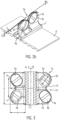
- the curved pocket 5a, 5b is directed to a first side, in Figure 4c to the left, curved outward.
- the pocket 6a, 6b curves toward the opposite side.
- Figure 4d shows a cross-section through the pockets 5a. The curvature creates a free space such that the wings can move past each other without collision.
- the upper (first) and lower (second) wing sections 3a, 3b, 4a, 4b of the opposing displacement elements 1a, 1b engage with each other in an interlocking manner.
- the topmost representation in Figure 4a shows how the displacement elements rotate in the direction of the arrow around the respective axes A1 and begin to divide the incoming sausage strand 11 and to displace the pasty mass.
- the pockets allow the wings to move past each other without blocking, and a distance between the two rotation axes of, for example, 50 mm to 150 mm can be achieved.
- the wings 2a, 2b move towards each other until they are in the dividing position, as shown in the bottom illustration in Figure 4a can be seen. If the sausage strand 11 to be filled is twisted via the twisting device, the twisting point 30 can now engage and the sausages are divided.
- the wings 2a, 2b then move apart again in the direction of the arrow.
- the pockets 5a, 5b, 6a, 6b allow the wings 2a, 2b to move apart again without collision.
- the drive is via a rotating mechanism 15 which can be connected to the holder 7, here via the driven shaft 16.
- the depth of the pocket p results from the center distance of the drive axles and the design of the displacement elements.
- the pockets bulge outwards at the sides and can, for example, be essentially oval.
- An opening (not shown) is also designed in such a way that the displacement elements can move past each other accordingly.
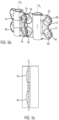
- Figure 5 c shows a further embodiment which is essentially the same as in connection with Figure 4 shown embodiment, with the exception that the displacement edges 13 of the upper and lower wing sections 3a, 3b, 4a, 4b of a respective displacement element lie in a common plane E1 at least in the region of the widening section 12, ie they are not offset from one another.
- this embodiment corresponds to the one described in connection with Figure 4a
- the wings 2a, 2b are arranged essentially parallel to one another, as can be seen from the bottom illustration in Figure 5a
- the recesses or pockets 5a, 5b, 6a, 6b allow the wings to move past one another without collision.
- the upper and lower wing sections 3a, 4a of the first displacement element lie in a plane Ea and the upper wing section 4a and the lower wing section 4b of the second displacement element 2b lie in a plane Eb parallel to plane Ea, which, as previously described, are parallel to a plane spanned by a vector along the axis of rotation A1 and a vector perpendicular to the axis of rotation A1.
- the distance between the planes is, for example, in particular in a range of the dimension of the displacement vane thickness in the region of the displacement edges in the widening region 12 plus +0 mm to 4 mm, in particular 0.1 to 3 mm, preferably 0.2 to 1 mm, at least in the region of the widening recess 12.
- Figure 5b shows in detail how the wings 2a, 2b can move towards each other.
- the sausage strand is conveyed in the transport direction T via a transport device not shown, e.g. by two opposing conveyor belts.
- the displacement elements each rotate around an axis A1, in particular the central axis - i.e., they rotate.
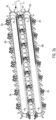
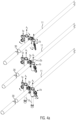
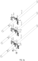
- the displacement elements can rotate around several axes of rotation A1, A2, as can be seen in particular from Figures 2a and 2b
- the displacement belts can be used both as in Figure 2a arranged one above the other.
- the axes can also be vertical, so that the two displacement belts are arranged next to each other. In this case, the first and second wing sections are not arranged one above the other, but next to each other. Otherwise, the design of the displacement elements is exactly the same as in the previous embodiments.
- a displacement element which here has a wing 2a
- the wing 2a has a first and second wing section 3a, 3b, which here, for example, as in connection with the Figures 4 shown embodiment, ie are arranged offset from one another.
- the first and second wing sections 3a, 3b and 4a, 4b can be arranged as in connection with the embodiment shown in Figure 5 shown embodiment be arranged in one plane.
- the wings 2a, 2b engage, as in connection with the Figures 4 and 5 shown, either crosswise into each other or lie parallel to each other.
- Figure 2a shown the first and second displacement elements 1a, 1b engage with one another in an interlocking manner.
- the two wings 2a, 2b are engaged, i.e. in the sectioning position. This is where the twist-off point can spring in.
- the displacement element pairs moved by the belts 8a, 8b carry the divided sausage strand in the transport direction T.
- the circulating transport means 8a, 8b thus also serve as a transport device.
- Guide elements can be arranged on the transport means between the displacement element pairs, which ensure that the sausage strand does not deviate sideways, especially in the case of longer sausages, but is conveyed along its longitudinal axis in the transport direction T.
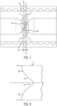
- Figure 7 shows that the parallel alignment of the displacement edges of the wings 2a, 2b and the small distance between the wings, at least in the area between the outer points O and U, which is preferably constant, can prevent a corresponding fold from forming between the wings of the displacement elements, as in Figure 6c has been shown.
- the wings 2a, 2b are arranged in two spaced parallel planes Ea, Eb.
- the displacement elements are designed such that the cutouts 12 overlap, particularly in a diamond shape, leaving a small opening so that the sausage strand is not sheared off.
- the pair of displacement elements or space them apart from one another such that the cutouts completely overlap and the sausage strand is severed to produce individual sausages.
- the displacement edge of at least one displacement element can be at least partially designed as a blade or have a blade.
- the device further comprises a twisting device 14 for rotating the sausage strand 11 to be filled about its longitudinal axis L and/or, for example, in the transport direction after the displacement elements 1a, 1b, a device for clipping or a device for tying or gluing or welding the sausage strand after displacement.
- a twisting device 14 for rotating the sausage strand 11 to be filled about its longitudinal axis L and/or, for example, in the transport direction after the displacement elements 1a, 1b, a device for clipping or a device for tying or gluing or welding the sausage strand after displacement.
- Figure 8 shows another possible embodiment of a wing that also has a V-shaped cutout 12 and is particularly suitable for larger calibers up to 60 mm.
- the wing sections are designed such that they have the largest dimension t at the top and bottom, i.e., points O and U are located at the top and bottom edges.
Landscapes
- Life Sciences & Earth Sciences (AREA)
- Engineering & Computer Science (AREA)
- Wood Science & Technology (AREA)
- Zoology (AREA)
- Food Science & Technology (AREA)
- Processing Of Meat And Fish (AREA)
- Meat, Egg Or Seafood Products (AREA)
- Food-Manufacturing Devices (AREA)
Priority Applications (1)
| Application Number | Priority Date | Filing Date | Title |
|---|---|---|---|
| EP25178827.9A EP4581933A3 (fr) | 2021-08-10 | 2021-08-10 | Paire d'éléments de déplacement |
Applications Claiming Priority (2)
| Application Number | Priority Date | Filing Date | Title |
|---|---|---|---|
| EP25178827.9A EP4581933A3 (fr) | 2021-08-10 | 2021-08-10 | Paire d'éléments de déplacement |
| EP21190588.0A EP4133942B1 (fr) | 2021-08-10 | 2021-08-10 | Paire d'éléments déplaceurs |
Related Parent Applications (2)
| Application Number | Title | Priority Date | Filing Date |
|---|---|---|---|
| EP21190588.0A Division-Into EP4133942B1 (fr) | 2021-08-10 | 2021-08-10 | Paire d'éléments déplaceurs |
| EP21190588.0A Division EP4133942B1 (fr) | 2021-08-10 | 2021-08-10 | Paire d'éléments déplaceurs |
Publications (2)
| Publication Number | Publication Date |
|---|---|
| EP4581933A2 true EP4581933A2 (fr) | 2025-07-09 |
| EP4581933A3 EP4581933A3 (fr) | 2025-10-08 |
Family
ID=77274744
Family Applications (2)
| Application Number | Title | Priority Date | Filing Date |
|---|---|---|---|
| EP25178827.9A Pending EP4581933A3 (fr) | 2021-08-10 | 2021-08-10 | Paire d'éléments de déplacement |
| EP21190588.0A Active EP4133942B1 (fr) | 2021-08-10 | 2021-08-10 | Paire d'éléments déplaceurs |
Family Applications After (1)
| Application Number | Title | Priority Date | Filing Date |
|---|---|---|---|
| EP21190588.0A Active EP4133942B1 (fr) | 2021-08-10 | 2021-08-10 | Paire d'éléments déplaceurs |
Country Status (6)
| Country | Link |
|---|---|
| US (1) | US12004523B2 (fr) |
| EP (2) | EP4581933A3 (fr) |
| JP (1) | JP7413638B2 (fr) |
| CN (2) | CN118575843A (fr) |
| BR (1) | BR102022015228A2 (fr) |
| ES (1) | ES3049113T3 (fr) |
Families Citing this family (1)
| Publication number | Priority date | Publication date | Assignee | Title |
|---|---|---|---|---|
| EP4474296A1 (fr) * | 2023-06-09 | 2024-12-11 | Albert Handtmann Maschinenfabrik GmbH & Co. KG | Dispositif et procédé de fabrication de récipients remplis d'un produit de remplissage liquide ou pâteux |
Family Cites Families (18)
| Publication number | Priority date | Publication date | Assignee | Title |
|---|---|---|---|---|
| US3264679A (en) * | 1963-12-24 | 1966-08-09 | Charles D Moekle | Apparatus for making linked products |
| US4418447A (en) * | 1981-07-02 | 1983-12-06 | Devro, Inc. | Method and apparatus for processing stuffed sausage casing |
| DE3401890A1 (de) * | 1984-01-20 | 1985-07-25 | Hoechst Ag, 6230 Frankfurt | Verwendung einer gerafften schlauchhuelle |
| US4905349A (en) * | 1989-03-06 | 1990-03-06 | Townsend Engineering Company | Encased product and method for encasing the same |
| DE3911859A1 (de) * | 1989-04-11 | 1990-10-18 | Handtmann Albert Maschf | Verfahren und vorrichtung zum abteilen eines von einer fuellmaschine kommenden durchgehenden wurststranges in einzelne wuerste |
| DE9012339U1 (de) * | 1990-08-28 | 1991-04-25 | Albert Handtmann Maschinenfabrik GmbH & Co KG, 7950 Biberach | Vorrichtung zum Abteilen eines von einer Füllmaschine kommenden durchgehenden Wurststranges in einzelne Würste |
| DE9012381U1 (de) * | 1990-08-29 | 1991-04-25 | Albert Handtmann Maschinenfabrik GmbH & Co KG, 7950 Biberach | Vorrichtung zum Abteilen eines von einer Füllmaschine kommenden durchgehenden Wurststranges in einzelne Würste |
| FR2725876B1 (fr) * | 1994-10-20 | 1997-01-17 | Nijal | Machine pour mettre un boyau garni sous forme de boyau torsade, notamment pour la mise en portions de saucisse |
| US5709600A (en) * | 1996-03-27 | 1998-01-20 | Townsend Engineering Company | Method and means for linking and then separating encased sausage |
| DE19802101C1 (de) * | 1998-01-21 | 1999-08-26 | Handtmann Albert Maschf | Vorrichtung und Verfahren zum Trennen von Würsten |
| ES2299788T3 (es) * | 2004-12-14 | 2008-06-01 | ALBERT HANDTMANN MASCHINENFABRIK GMBH & CO. KG | Dispositivo de conformado y procedimiento de conformado para formar cabezas de extremos de embutidos. |
| EP1902622B1 (fr) * | 2006-09-19 | 2009-01-07 | Albert Handtmann Maschinenfabrik GmbH & Co. KG | Procédé et dispositif pour diviser un chapelet de saucisses |
| US7704131B1 (en) * | 2008-12-30 | 2010-04-27 | Kraft Foods Global Brands Llc | Apparatus for forming spaced intervals in a stuffed casing and method thereof |
| DK2213177T4 (en) * | 2009-01-28 | 2016-01-25 | Handtmann Albert Maschf | Device and method for pølsetarmsskånende division of the filled sausage strands |
| CN104229131A (zh) | 2014-10-13 | 2014-12-24 | 新誉集团有限公司 | V型八旋翼航拍飞行器 |
| WO2017081648A1 (fr) * | 2015-11-13 | 2017-05-18 | Freddy Hirsch Group Ag | Appareil de coupe de saucisse |
| GB2560560B (en) | 2017-03-15 | 2019-05-08 | Freddy Hirsch Group Pty Limited | A sausage cutting apparatus |
| DE102021112517B3 (de) * | 2021-05-12 | 2022-04-14 | Vemag Maschinenbau Gmbh | Trennvorrichtung zum Trennen von Portionen aus mit Lebensmittel-Masse befüllten, länglichen Hüllen sowie betreffendes Verfahren |
-
2021
- 2021-08-10 ES ES21190588T patent/ES3049113T3/es active Active
- 2021-08-10 EP EP25178827.9A patent/EP4581933A3/fr active Pending
- 2021-08-10 EP EP21190588.0A patent/EP4133942B1/fr active Active
-
2022
- 2022-07-22 JP JP2022117343A patent/JP7413638B2/ja active Active
- 2022-08-01 BR BR102022015228-4A patent/BR102022015228A2/pt unknown
- 2022-08-04 CN CN202410843470.8A patent/CN118575843A/zh active Pending
- 2022-08-04 CN CN202210932506.0A patent/CN115702649B/zh active Active
- 2022-08-10 US US17/885,465 patent/US12004523B2/en active Active
Also Published As
| Publication number | Publication date |
|---|---|
| EP4133942B1 (fr) | 2025-10-08 |
| US20230047261A1 (en) | 2023-02-16 |
| EP4133942A1 (fr) | 2023-02-15 |
| CN118575843A (zh) | 2024-09-03 |
| CN115702649A (zh) | 2023-02-17 |
| ES3049113T3 (en) | 2025-12-15 |
| CN115702649B (zh) | 2024-07-16 |
| JP7413638B2 (ja) | 2024-01-16 |
| US12004523B2 (en) | 2024-06-11 |
| EP4581933A3 (fr) | 2025-10-08 |
| EP4133942C0 (fr) | 2025-10-08 |
| BR102022015228A2 (pt) | 2023-03-07 |
| JP2023025680A (ja) | 2023-02-22 |
Similar Documents
| Publication | Publication Date | Title |
|---|---|---|
| EP0392083B1 (fr) | Procédé et dispositif pour diviser un chapelet de saucisses formé par une machine de bourrage en saucisses séparées | |
| EP1902622B1 (fr) | Procédé et dispositif pour diviser un chapelet de saucisses | |
| EP0440039B1 (fr) | Procédé et dispositif pour la fabrication de saucisses en chapelet et pour leur division en saucisses séparées ou en groupes de saucisses connectées | |
| EP3458257B1 (fr) | Dispositif et procédé permettant de comprimer des corps creux par écrasement | |
| DE102021112513B3 (de) | Portioniervorrichtung - und Verfahren sowie Crimpelement | |
| EP4133942B1 (fr) | Paire d'éléments déplaceurs | |
| EP0472825A1 (fr) | Dispositif pour diviser un chapelet de saucisses formé par une machine de bourrage en saucisses | |
| EP4088581B1 (fr) | Dispositif de séparation permettant de séparer des portions des enveloppes oblongues remplies de masse alimentaire, ainsi que procédé correspondant | |
| DE3702954A1 (de) | Gruppiereinrichtung zur bildung von behaeltergruppen | |
| EP3967146B1 (fr) | Dispositif et procédé de division en portions | |
| EP3449730B1 (fr) | Dispositif de séparation des manchons tubulaires | |
| DE2146554C3 (de) | Verfahren und Vorrichtung zum LangroUen und/oder Langwirken von Teigstucken Fr. Winkler KG, Spezialfabrik für Bäckereimaschinen und Backöfen, 7730 Villingen | |
| EP2213177B1 (fr) | Dispositif et procédé de séparation préservant les enveloppes de chapelets de saucisses remplis | |
| DE102008039154A1 (de) | Schneckenschwertlagerung | |
| EP4014744A1 (fr) | Dispositif et procédé de rétrécissement et/ou de séparation d'un chapelet de saucisses | |
| DE102021125587B3 (de) | Vorrichtung und Verfahren zum Ausrichten von Würsten | |
| EP0474970A1 (fr) | Dispositif pour diviser un chapelet de saucisses formé par une machine de bourrage en saucisses séparées | |
| EP4303141B1 (fr) | Dispositif de séparation destiné à séparer des portions de boyaux allongées remplies de masse alimentaire, élément de sertissage correspondant et procédé | |
| EP1671546A1 (fr) | Appareil de moulage et procédé de moulage pour mouler des dômes aux extrémités de saucisses | |
| AT503921B1 (de) | Vorrichtung zum fördern und übergeben von gegenständen | |
| DE3408859A1 (de) | Wurstfuellmaschine mit einer vorrichtung zur zipfelbildung und einer abschneideinrichtung fuer die wuerste | |
| DE102023108714A1 (de) | Verfahren zum parallelen Erstellen von geschindelten Portionen mit unterschiedlicher Scheiben-Anzahl sowie hierfür geeignete Aufschneide-Maschine | |
| EP4603421A1 (fr) | Dispositif de transport pour transporter des portions d'enveloppes allongées remplies de masse alimentaire, dispositif de séparation correspondant, procédé et utilisation | |
| DE1075420B (de) | Vorrichtung zum Verformen einer Materialbahn von mit wellenförmigen Taschen vesehenem Verpackungsmaterial | |
| DE2262064A1 (de) | Vorrichtung zum trennen von mit einem deckblattstreifen umhuellten zigarrenwickeln |
Legal Events
| Date | Code | Title | Description |
|---|---|---|---|
| PUAI | Public reference made under article 153(3) epc to a published international application that has entered the european phase |
Free format text: ORIGINAL CODE: 0009012 |
|
| STAA | Information on the status of an ep patent application or granted ep patent |
Free format text: STATUS: THE APPLICATION HAS BEEN PUBLISHED |
|
| AC | Divisional application: reference to earlier application |
Ref document number: 4133942 Country of ref document: EP Kind code of ref document: P |
|
| AK | Designated contracting states |
Kind code of ref document: A2 Designated state(s): AL AT BE BG CH CY CZ DE DK EE ES FI FR GB GR HR HU IE IS IT LI LT LU LV MC MK MT NL NO PL PT RO RS SE SI SK SM TR |
|
| PUAL | Search report despatched |
Free format text: ORIGINAL CODE: 0009013 |
|
| AK | Designated contracting states |
Kind code of ref document: A3 Designated state(s): AL AT BE BG CH CY CZ DE DK EE ES FI FR GB GR HR HU IE IS IT LI LT LU LV MC MK MT NL NO PL PT RO RS SE SI SK SM TR |
|
| RIC1 | Information provided on ipc code assigned before grant |
Ipc: A22C 11/10 20060101AFI20250829BHEP |