EP4581933A2 - Pair of displacement elements - Google Patents
Pair of displacement elements Download PDFInfo
- Publication number
- EP4581933A2 EP4581933A2 EP25178827.9A EP25178827A EP4581933A2 EP 4581933 A2 EP4581933 A2 EP 4581933A2 EP 25178827 A EP25178827 A EP 25178827A EP 4581933 A2 EP4581933 A2 EP 4581933A2
- Authority
- EP
- European Patent Office
- Prior art keywords
- displacement
- wing
- elements
- displacement elements
- wing section
- Prior art date
- Legal status (The legal status is an assumption and is not a legal conclusion. Google has not performed a legal analysis and makes no representation as to the accuracy of the status listed.)
- Pending
Links
Images
Classifications
-
- A—HUMAN NECESSITIES
- A22—BUTCHERING; MEAT TREATMENT; PROCESSING POULTRY OR FISH
- A22C—PROCESSING MEAT, POULTRY, OR FISH
- A22C11/00—Sausage making ; Apparatus for handling or conveying sausage products during manufacture
- A22C11/12—Apparatus for tying sausage skins ; Clipping sausage skins
-
- A—HUMAN NECESSITIES
- A22—BUTCHERING; MEAT TREATMENT; PROCESSING POULTRY OR FISH
- A22C—PROCESSING MEAT, POULTRY, OR FISH
- A22C11/00—Sausage making ; Apparatus for handling or conveying sausage products during manufacture
- A22C11/006—Separating linked sausages
-
- A—HUMAN NECESSITIES
- A22—BUTCHERING; MEAT TREATMENT; PROCESSING POULTRY OR FISH
- A22C—PROCESSING MEAT, POULTRY, OR FISH
- A22C11/00—Sausage making ; Apparatus for handling or conveying sausage products during manufacture
- A22C11/10—Apparatus for twisting or linking sausages
- A22C11/104—Apparatus for twisting or linking sausages by means of shear or blade elements
-
- A—HUMAN NECESSITIES
- A22—BUTCHERING; MEAT TREATMENT; PROCESSING POULTRY OR FISH
- A22C—PROCESSING MEAT, POULTRY, OR FISH
- A22C11/00—Sausage making ; Apparatus for handling or conveying sausage products during manufacture
- A22C11/10—Apparatus for twisting or linking sausages
- A22C11/107—A string passing between two rotary members comprising dividing elements cooperating with each other
Definitions
- the invention relates to a pair of displacement elements and a device for dividing a sausage strand with such a pair of displacement elements according to the preamble of claims 1 and 7.
- a pasty mass is filled into a sausage casing, for example, via a filling tube, creating a filled sausage strand.
- so-called displacing elements are used to displace the pasty mass in the product strand at predetermined intervals, particularly to create a constriction.
- the sausage strand to be filled can be twisted around its longitudinal axis, for example, using a twisting unit, whereby a twisting point then occurs at the constriction point, thus dividing the sausage strand.
- folds form between the displacing elements during constriction.
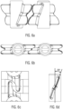
- Figure 6a shows a perspective view of two opposing displacement elements according to the prior art, which are rotated in opposite directions about their respective axes A.
- the sausage strand moves between the displacement elements.
- each displacement element has at least one vane with an upper vane section and a lower vane section, which, as shown in Figure 6b shown, interlock in a compartment position.
- the opposite upper wing sections and the opposite lower wing sections each run at an angle of, for example, 2 times 20 ° to each other.
- the present invention is based on the object of providing improved displacement elements for a device for dividing a sausage strand, which enable the dividing point to intervene quickly and gently.
- a pair of displacement elements is provided for dividing a sausage strand transported between the displacement elements into individual sausages.
- Each displacement element has at least one wing, which has a first wing section and a second wing section, between which an outwardly widening, in particular V-shaped, cutout is formed.
- Both the first, e.g., upper, and the second, e.g., lower, wing sections each have a laterally curved pocket or opening.
- the curved pocket or opening each located in an area within the outer contour of the respective wing section, allows the displacement elements to move past one another in such a way that the wing sections do not collide during rotation because, for example, a first wing section can move past the area of the curved pocket of the corresponding wing section of the opposite displacement element, i.e., can move through the free space created by the pocket or opening.
- the displacement edge i.e. the outer contour of the first and second wing sections of a respective displacement element, lies at least in the region of the widening cutout either a) in substantially parallel planes or b) in a common plane. If the displacement edges of the first and second wing sections lie in parallel planes, the wings can interlock in order to separate the sausage strand. If the displacement edges of the first and second wing sections lie in a common plane, the separation can be achieved by wings that are parallel to one another. The planes in particular each run accordingly through the center of the wing width in the region of the widening section.
- This arrangement makes it possible to keep the distance between the wings of the opposing displacement elements small in a sectioning position, at least in the area of the outwardly widening, particularly V-shaped, section.
- the distance can also be essentially constant.
- the wing sections do not diverge as in the prior art, effectively preventing the formation of wrinkles and twisting the sausage strand in a very short time during twisting, and the twisting point springs into place. The sectioning point is thus created more gently overall.
- the distance between the planes is preferably within the following range: the thickness of the wing sections + 0 mm to 4 mm, in particular the thickness + 0.1 mm to 3 mm, in particular + 0.2 mm to 1 mm. In this range, no jamming occurs, and the turning point snaps into place quickly and completely.
- the thickness, in particular the maximum thickness (if the thickness is not constant), of the wing sections in the expanding cutout is considered.
- the curved pocket in the first wing section of a respective displacement element is curved outwardly to a first side, and in the second wing section, the curved pocket is curved to the opposite side.
- the curved pockets in the first and second wing sections are curved to the same side.
- the wing of the first displacement element and the wing of the second opposite displacement element can interlock or the wings can be arranged substantially parallel to one another.
- the vanes can be arranged in a flag-like manner on a mount, via which they can be connected to a rotating mechanism, which in particular comprises a drive shaft, in order to rotate the displacement elements about an axis or to move them in rotation about multiple axes.
- a rotating mechanism which in particular comprises a drive shaft
- the displacement elements are either rotated at a distance from one another about, for example, their central axis, or are each mounted on a transport means, e.g., a chain or conveyor belt, etc., and rotate.
- the displacement elements of the invention even when rotated or circulated, offer the same advantages as linearly moving displacement elements, whose vanes can be arranged very close to each other in the compartment position.
- the rotational or circulating movement can increase the production speed.
- a device for dividing a sausage strand comprises at least one pair of displacement elements according to at least one of claims 1-6. Furthermore, the device comprises a transport device for transporting the filled sausage strand between the opposing displacement elements. Furthermore, the device comprises a rotation mechanism for rotating the displacement elements about a respective rotation axis or for rotating them about multiple rotation axes.
- the displacement elements can also displace the pasty mass without a twisting device
- a twisting device for rotating the sausage strand around its longitudinal axis L is advantageous so that a twisting point can be created between the individual sausages.
- no twisting device is necessary in coextruded sausages, in which a sausage casing is extruded together with the pasty mass.
- the present invention is advantageous because a well-formed separation point can be created without oblique squeezing.
- the displacement elements can be rotated about their central axis A1 via the rotation mechanism, with the central axis running essentially parallel to the planes E1, E2, in which the displacement edge of the wing sections lies at least in the region of the widening cutout.
- the central axis or rotation axis extends perpendicular to the transport direction T of the sausage strand.
- the opposing displacement elements are each arranged on two transport means rotating around multiple axes, in particular a transport chain or a conveyor belt.
- the axes of rotation are preferably substantially parallel to the planes in which the displacement edges of the first and second wing sections are arranged in the region of the particularly V-shaped cutout.
- the axes of rotation preferably run perpendicular to the transport direction of the sausage strand.
- a displacement element has several rotating vanes, or several displacement elements, each with a vane, are arranged on the respective rotating transport means. This allows the throughput to be increased.
- the displacement elements are manufactured using 3D printing or injection molding.
- 3D printing makes it particularly easy to manufacture a displacement element that features the pockets or recesses according to the invention.
- metal displacement elements can also be manufactured using 3D printing.
- a transport device 16 is shown only as an example, which has opposite, circulating transport means, e.g. conveyor belts or transport chains, etc., between which the filled sausage strand 11 is transported.
- the displacement elements 1a, 1b are arranged on the circulating transport means, e.g. the circulating conveyor belt, chain, etc., in particular at uniform intervals.
- the circulating transport means e.g. the circulating conveyor belt, chain, etc.
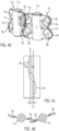
- FIG. 3 schematically shows a displacement element according to an embodiment of the invention.
- the displacement element has at least one wing 2a, with an upper, i.e., first, wing section 3a and a lower, i.e., second, wing section 4a. Between the two wing sections, an outwardly widening, in particular V-shaped, open-edge cutout 12 is provided. The displacement edges 13 are arranged in the region of the V-shaped cutout 12.
- the outward extension k of the lower and upper wing sections 3a, 4a is, for example, in a range from 30 mm to 80 mm.
- the thickness of the wings for example, ranges from 1 mm to 6 mm, preferably from 1 mm to 3 mm.
- Corresponding displacement elements are suitable for sausage calibers ranging from 8 mm to 60 mm.
- the invention also enables the use of the displacement elements in conjunction with clipping machines that process larger sausage diameters (e.g., up to 60 mm).
- Both the upper and lower wing sections 3a, 4a have laterally curved pockets 5a, 6a, which allow opposing displacement elements to move past each other without collision, i.e. the outermost points O and U of the outer contour or the displacement edges 13 can move through the free space formed by the pockets.
- the pockets 5a, 5b, 6a, 6b it is also possible to simply create an opening in the surface of the upper and lower wing sections within the outer contour of the wings. This also allows the wings to move past each other without any problems.
- the solution with the pockets provides improved stability, and the sausage string can be better supported during separation.
- the wing sections 3a, 4a border on one another in a transition region.
- the planes E1 and E2 are preferably parallel to the axis of rotation, in particular parallel to a plane which is spanned by a vector along the axis of rotation A1 and a vector perpendicular to the axis of rotation A1.
- the curved pocket 5a, 5b is directed to a first side, in Figure 4c to the left, curved outward.
- the pocket 6a, 6b curves toward the opposite side.
- Figure 4d shows a cross-section through the pockets 5a. The curvature creates a free space such that the wings can move past each other without collision.
- the upper (first) and lower (second) wing sections 3a, 3b, 4a, 4b of the opposing displacement elements 1a, 1b engage with each other in an interlocking manner.
- the topmost representation in Figure 4a shows how the displacement elements rotate in the direction of the arrow around the respective axes A1 and begin to divide the incoming sausage strand 11 and to displace the pasty mass.
- the pockets allow the wings to move past each other without blocking, and a distance between the two rotation axes of, for example, 50 mm to 150 mm can be achieved.
- the wings 2a, 2b move towards each other until they are in the dividing position, as shown in the bottom illustration in Figure 4a can be seen. If the sausage strand 11 to be filled is twisted via the twisting device, the twisting point 30 can now engage and the sausages are divided.
- the wings 2a, 2b then move apart again in the direction of the arrow.
- the pockets 5a, 5b, 6a, 6b allow the wings 2a, 2b to move apart again without collision.
- the drive is via a rotating mechanism 15 which can be connected to the holder 7, here via the driven shaft 16.
- the depth of the pocket p results from the center distance of the drive axles and the design of the displacement elements.
- the pockets bulge outwards at the sides and can, for example, be essentially oval.
- An opening (not shown) is also designed in such a way that the displacement elements can move past each other accordingly.
- Figure 5 c shows a further embodiment which is essentially the same as in connection with Figure 4 shown embodiment, with the exception that the displacement edges 13 of the upper and lower wing sections 3a, 3b, 4a, 4b of a respective displacement element lie in a common plane E1 at least in the region of the widening section 12, ie they are not offset from one another.
- this embodiment corresponds to the one described in connection with Figure 4a
- the wings 2a, 2b are arranged essentially parallel to one another, as can be seen from the bottom illustration in Figure 5a
- the recesses or pockets 5a, 5b, 6a, 6b allow the wings to move past one another without collision.
- the upper and lower wing sections 3a, 4a of the first displacement element lie in a plane Ea and the upper wing section 4a and the lower wing section 4b of the second displacement element 2b lie in a plane Eb parallel to plane Ea, which, as previously described, are parallel to a plane spanned by a vector along the axis of rotation A1 and a vector perpendicular to the axis of rotation A1.
- the distance between the planes is, for example, in particular in a range of the dimension of the displacement vane thickness in the region of the displacement edges in the widening region 12 plus +0 mm to 4 mm, in particular 0.1 to 3 mm, preferably 0.2 to 1 mm, at least in the region of the widening recess 12.
- Figure 5b shows in detail how the wings 2a, 2b can move towards each other.
- the sausage strand is conveyed in the transport direction T via a transport device not shown, e.g. by two opposing conveyor belts.
- the displacement elements each rotate around an axis A1, in particular the central axis - i.e., they rotate.
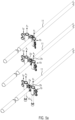
- the displacement elements can rotate around several axes of rotation A1, A2, as can be seen in particular from Figures 2a and 2b
- the displacement belts can be used both as in Figure 2a arranged one above the other.
- the axes can also be vertical, so that the two displacement belts are arranged next to each other. In this case, the first and second wing sections are not arranged one above the other, but next to each other. Otherwise, the design of the displacement elements is exactly the same as in the previous embodiments.
- a displacement element which here has a wing 2a
- the wing 2a has a first and second wing section 3a, 3b, which here, for example, as in connection with the Figures 4 shown embodiment, ie are arranged offset from one another.
- the first and second wing sections 3a, 3b and 4a, 4b can be arranged as in connection with the embodiment shown in Figure 5 shown embodiment be arranged in one plane.
- the wings 2a, 2b engage, as in connection with the Figures 4 and 5 shown, either crosswise into each other or lie parallel to each other.
- Figure 2a shown the first and second displacement elements 1a, 1b engage with one another in an interlocking manner.
- the two wings 2a, 2b are engaged, i.e. in the sectioning position. This is where the twist-off point can spring in.
- the displacement element pairs moved by the belts 8a, 8b carry the divided sausage strand in the transport direction T.
- the circulating transport means 8a, 8b thus also serve as a transport device.
- Guide elements can be arranged on the transport means between the displacement element pairs, which ensure that the sausage strand does not deviate sideways, especially in the case of longer sausages, but is conveyed along its longitudinal axis in the transport direction T.
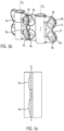
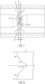
- Figure 7 shows that the parallel alignment of the displacement edges of the wings 2a, 2b and the small distance between the wings, at least in the area between the outer points O and U, which is preferably constant, can prevent a corresponding fold from forming between the wings of the displacement elements, as in Figure 6c has been shown.
- the wings 2a, 2b are arranged in two spaced parallel planes Ea, Eb.
- the displacement elements are designed such that the cutouts 12 overlap, particularly in a diamond shape, leaving a small opening so that the sausage strand is not sheared off.
- the pair of displacement elements or space them apart from one another such that the cutouts completely overlap and the sausage strand is severed to produce individual sausages.
- the displacement edge of at least one displacement element can be at least partially designed as a blade or have a blade.
- the device further comprises a twisting device 14 for rotating the sausage strand 11 to be filled about its longitudinal axis L and/or, for example, in the transport direction after the displacement elements 1a, 1b, a device for clipping or a device for tying or gluing or welding the sausage strand after displacement.
- a twisting device 14 for rotating the sausage strand 11 to be filled about its longitudinal axis L and/or, for example, in the transport direction after the displacement elements 1a, 1b, a device for clipping or a device for tying or gluing or welding the sausage strand after displacement.
- Figure 8 shows another possible embodiment of a wing that also has a V-shaped cutout 12 and is particularly suitable for larger calibers up to 60 mm.
- the wing sections are designed such that they have the largest dimension t at the top and bottom, i.e., points O and U are located at the top and bottom edges.
Landscapes
- Life Sciences & Earth Sciences (AREA)
- Engineering & Computer Science (AREA)
- Wood Science & Technology (AREA)
- Zoology (AREA)
- Food Science & Technology (AREA)
- Processing Of Meat And Fish (AREA)
- Meat, Egg Or Seafood Products (AREA)
- Food-Manufacturing Devices (AREA)
Abstract
Die Erfindung betrifft ein Verdrängerelementepaar (1a, 1b) zum Abteilen eines zwischen den Verdrängerelementen (1a, 1b) transportierten Wurststrangs (11) in Einzelwürste, wobei jedes Verdrängerelement (1a, 1b) mindestens einen Flügel (2a, 2b) mit einem ersten Flügelabschnitt (3a, 3b) und einem zweiten Flügelabschnitt (4a, 4b) aufweist, zwischen denen ein sich nach außen erweiternder, insbesondere V-förmiger Ausschnitt (12) ausgebildet ist, dadurch gekennzeichnet, dass sowohl der erste als auch der zweite Flügelabschnitt (3a, b), (4a, b) eine zur Seite gewölbte Tasche (5a, 5b, 6a, 6b) aufweist und die Verdrängerkanten (13) des ersten und zweiten Flügelabschnitts (2a, 2b), (3a, 3b) eines jeweiligen Verdrängerelements (1a, 1b) zumindest im Bereich des sich erweiternden Abschnitts (12) in im Wesentlichen parallelen Ebenen (E1, E2) liegen.

Description
Die Erfindung betrifft ein Verdrängerelementepaar, sowie eine Vorrichtung zum Abteilen eines Wurststrangs mit einem solchen Verdrängerelementepaar gemäß dem Oberbegriff der Ansprüche 1 und 7.The invention relates to a pair of displacement elements and a device for dividing a sausage strand with such a pair of displacement elements according to the preamble of
Zum Herstellen von Würsten wird pastöse Masse z.B. über ein Füllrohr in eine Wursthülle gefüllt, wodurch ein gefüllter Wurststrang erzeugt wird. Um einen solchen "endlos" gefüllten Wurststrang beim Füllen in gleich lange Portionen abzuteilen, wird mit sogenannten gegenüberliegenden Verdrängerelementen die pastöse Masse im Produktstrang in vorgegebenen Abständen verdrängt, insbesondere eine Einschnürstelle erzeugt. Der zu befüllende Wurststrang kann dazu z.B. über eine Abdreheinheit um seine Längsachse verdrillt werden, wobei dann an der Einschnürstelle eine Abdrehstelle einspringt und der Wurststrang somit unterteilt ist. Bei der Produktion mit Verdrängerelementen, wie sie derzeit am Markt verfügbar sind, bilden sich zwischen den Verdrängerelementen beim Einschnüren Falten, die das Verdrillen der Einschnürstelle und das Einspringen der Abdrehstelle zwar nicht verhindern, aber dennoch verzögern können, d.h., dass die Abdrehstelle später einspringt, d.h. in Transportrichtung betrachtet, erst weiter hinten einspringt. Das bedeutet, dass die Erzeugung der Abdrehstelle, bzw. Abteilstelle länger dauert und die Produkthülle stärker belastet wird. Empfindliche Wursthüllen können beim Verdrängen beschädigt werden, wodurch die Produktion stark beeinträchtigt wird.To produce sausages, a pasty mass is filled into a sausage casing, for example, via a filling tube, creating a filled sausage strand. To divide such an "endlessly" filled sausage strand into equal-length portions during filling, so-called displacing elements are used to displace the pasty mass in the product strand at predetermined intervals, particularly to create a constriction. For this purpose, the sausage strand to be filled can be twisted around its longitudinal axis, for example, using a twisting unit, whereby a twisting point then occurs at the constriction point, thus dividing the sausage strand. During production with displacing elements, as currently available on the market, folds form between the displacing elements during constriction. These folds cannot prevent the twisting of the constriction point and the twisting point, but can nevertheless delay it, meaning that the twisting point occurs later, i.e., further back in the transport direction. This means that creating the twist-off point or split point takes longer and places greater stress on the product casing. Delicate sausage casings can be damaged during the displacement process, severely impacting production.
Hiervon ausgehend liegt der vorliegenden Erfindung die Aufgabe zugrunde, verbesserte Verdrängerelemente für eine Vorrichtung zum Abteilen eines Wurststrangs bereitzustellen, die ermöglichen, dass die Abteilstelle schnell und schonend einspringen kann.Based on this, the present invention is based on the object of providing improved displacement elements for a device for dividing a sausage strand, which enable the dividing point to intervene quickly and gently.
Erfindungsgemäß wird diese Aufgabe durch die Merkmale des Anspruchs 1 gelöst.According to the invention, this object is achieved by the features of
Gemäß der vorliegenden Erfindung ist ein Verdrängerelementepaar zum Abteilen eines zwischen den Verdrängerelementen transportierten Wurststrangs in Einzelwürste vorgesehen. Jedes Verdrängerelement weist mindestens einen Flügel auf, der einen ersten Flügelabschnitt und einen zweiten Flügelabschnitt ausweist, zwischen denen ein sich nach außen erweiternder, insbesondere V-förmiger Ausschnitt ausgebildet ist. Sowohl der erste, also z.B. obere als auch der zweite, z.B. untere Flügelabschnitt weisen jeweils eine zur Seite gewölbte Tasche oder Öffnung auf.According to the present invention, a pair of displacement elements is provided for dividing a sausage strand transported between the displacement elements into individual sausages. Each displacement element has at least one wing, which has a first wing section and a second wing section, between which an outwardly widening, in particular V-shaped, cutout is formed. Both the first, e.g., upper, and the second, e.g., lower, wing sections each have a laterally curved pocket or opening.
Die gewölbte Tasche oder Öffnung, die jeweils in einem Bereich innerhalb der Außenkontur des jeweiligen Flügelabschnitts liegen, ermöglicht, dass sich die Verdrängerelemente aneinander vorbei bewegen können, derart, dass die Flügelabschnitte während der Umdrehung nicht aneinander stoßen, weil z.B. ein erster Flügelabschnitt sich im Bereich der gewölbten Tasche des entsprechenden Flügelabschnitts des gegenüberliegenden Verdrängerelements vorbei bewegen kann, d.h. sich durch den durch die Tasche oder Öffnung geschaffenen Freiraum bewegen kann. Somit wird ermöglicht, dass in einer Abteilposition, in der der Wurststrang maximal eingeschnürt ist und sich die beiden erweiternden, insbesondere V-förmigen Ausschnitte maximal überlagern, die ersten und zweiten Flügelabschnitte der jeweiligen Verdrängerelemente im Wesentlichen parallel mit geringem Abstand zueinander angeordnet werden können, sodass eine Faltenbildung zwischen den Flächen der Flügelabschnitte verhindert werden und die Abdrehstelle schneller und schonender einspringen kann.The curved pocket or opening, each located in an area within the outer contour of the respective wing section, allows the displacement elements to move past one another in such a way that the wing sections do not collide during rotation because, for example, a first wing section can move past the area of the curved pocket of the corresponding wing section of the opposite displacement element, i.e., can move through the free space created by the pocket or opening. This makes it possible, in a sectioning position in which the sausage strand is maximally constricted and the two widening, particularly V-shaped cutouts maximally overlap, for the first and second wing sections of the respective displacement elements to be arranged essentially parallel with a small distance from one another, thus preventing the formation of wrinkles between the surfaces of the wing sections and allowing the twist-off point to spring into place more quickly and gently.
Gemäß einem bevorzugten Ausführungsbeispiel liegt die Verdrängerkante, d.h. die Außenkontur des ersten und zweiten Flügelabschnitts eines jeweiligen Verdrängerelements zumindest im Bereich des sich erweiternden Ausschnitts entweder a) in im Wesentlichen parallelen Ebenen oder b) in einer gemeinsamen Ebene. Wenn die Verdrängerkanten des ersten und zweiten Flügelabschnitts in parallelen Ebenen liegen, können die Flügel verschränkt ineinandergreifen, um den Wurststrang abzuteilen. Wenn die Verdrängerkanten des ersten und zweiten Flügelabschnitts in einer gemeinsamen Ebene liegen, kann das Abteilen durch parallel zueinanderstehende Flügel bewerkstelligt werden. Die Ebenen verlaufen dabei insbesondere jeweils entsprechend durch die Mitte der Flügelbreite im Bereich des sich erweiternden Abschnitts.According to a preferred embodiment, the displacement edge, i.e. the outer contour of the first and second wing sections of a respective displacement element, lies at least in the region of the widening cutout either a) in substantially parallel planes or b) in a common plane. If the displacement edges of the first and second wing sections lie in parallel planes, the wings can interlock in order to separate the sausage strand. If the displacement edges of the first and second wing sections lie in a common plane, the separation can be achieved by wings that are parallel to one another. The planes in particular each run accordingly through the center of the wing width in the region of the widening section.
Durch diese Anordnung ist es möglich, dass der Abstand zwischen den Flügeln der gegenüberliegenden Verdrängerelemente in einer Abteilposition zumindest im Bereich des sich nach außen erweiternden, insbesondere V-förmigen Abschnitts, klein gehalten werden kann. Der Abstand kann dabei auch im Wesentlichen konstant sein. Die Flügelabschnitte laufen nicht wie im Stand der Technik auseinander, sodass eine Faltenbildung wirksam verhindert werden kann und der Wurststrang beim Abdrehen in kürzester Zeit verdrillt und die Abdrehstelle einspringt. Die Abteilstelle wird somit insgesamt schonender erzeugt.This arrangement makes it possible to keep the distance between the wings of the opposing displacement elements small in a sectioning position, at least in the area of the outwardly widening, particularly V-shaped, section. The distance can also be essentially constant. The wing sections do not diverge as in the prior art, effectively preventing the formation of wrinkles and twisting the sausage strand in a very short time during twisting, and the twisting point springs into place. The sectioning point is thus created more gently overall.
In Abhängigkeit der Dicke der Flügelelemente liegt der Abstand der Ebenen voneinander vorzugsweise in folgendem Bereich: Betrag der Dicke der Flügelabschnitte + 0 mm bis 4 mm, insbesondere Betrag der Dicke + 0,1 mm bis 3 mm, insbesondere + 0,2 mm bis 1 mm. In diesem Bereich kommt es zu keinem Einklemmen und die Abdrehstelle springt schnell und vollständig ein. Hier wird die Dicke, insbesondere maximale Dicke (bei nicht konstanter Dicke) der Flügelabschnitte im sich erweiternden Ausschnitt betrachtet.Depending on the thickness of the wing elements, the distance between the planes is preferably within the following range: the thickness of the wing sections + 0 mm to 4 mm, in particular the thickness + 0.1 mm to 3 mm, in particular + 0.2 mm to 1 mm. In this range, no jamming occurs, and the turning point snaps into place quickly and completely. Here, the thickness, in particular the maximum thickness (if the thickness is not constant), of the wing sections in the expanding cutout is considered.
Vorteilhafterweise ist im Fall a) im ersten Flügelabschnitt eines jeweiligen Verdrängerelements die gewölbte Tasche zu einer ersten Seite nach außen gewölbt und im zweiten Flügelabschnitt die gewölbte Tasche zur gegenüberliegenden Seite gewölbt und im Fall b) die gewölbten Taschen im ersten und zweiten Flügelabschnitt zur gleichen Seite gewölbt. Somit können sich die Flügelabschnitte ohne Kollision aneinander vorbei bewegen.Advantageously, in case a), the curved pocket in the first wing section of a respective displacement element is curved outwardly to a first side, and in the second wing section, the curved pocket is curved to the opposite side. In case b), the curved pockets in the first and second wing sections are curved to the same side. Thus, the wing sections can move past each other without collision.
Gemäß einem bevorzugten Ausführungsbeispiel können in einer Abteilposition, in der der Wurststrang maximal eingeschnürt ist und die beiden sich erweiternden Ausschnitte maximal überlagert sind, der Flügel des ersten Verdrängerelements und der Flügel des zweiten gegenüberliegenden Verdrängerelements verschränkt ineinandergreifen oder die Flügel im Wesentlichen parallel nebeneinander angeordnet sein.According to a preferred embodiment, in a compartmentalizing position in which the sausage strand is maximally constricted and the two widening cutouts are maximally superimposed, the wing of the first displacement element and the wing of the second opposite displacement element can interlock or the wings can be arranged substantially parallel to one another.
Gemäß einer bevorzugten Ausführungsform können die Flügel fahnenartig an einer Halterung angeordnet sein, über die sie mit einem Drehmechanismus, der insbesondere eine Antriebswelle umfasst, verbindbar sind, um die Verdrängerelemente um eine Achse zu drehen oder umlaufend um mehrere Achsen zu bewegen. Das heißt, dass die Verdrängerelemente entweder beabstandet zueinander um z.B. ihre Mittelachse gedreht werden oder aber jeweils auf einem Transportmittel, z.B. Kette oder Transportband etc. befestigt sind und umlaufen.According to a preferred embodiment, the vanes can be arranged in a flag-like manner on a mount, via which they can be connected to a rotating mechanism, which in particular comprises a drive shaft, in order to rotate the displacement elements about an axis or to move them in rotation about multiple axes. This means that the displacement elements are either rotated at a distance from one another about, for example, their central axis, or are each mounted on a transport means, e.g., a chain or conveyor belt, etc., and rotate.
Die Verdrängerelemente der Erfindung weisen, selbst wenn sie gedreht werden oder umlaufen, die gleichen Vorteile auf, die linear aufeinander zu bewegte Verdrängerelemente aufweisen, deren Flügel in der Abteilposition sehr nah zueinander angeordnet werden können. Durch die Drehbewegung oder umlaufende Bewegung kann jedoch gemäß der Erfindung die Produktionsgeschwindigkeit erhöht werden.The displacement elements of the invention, even when rotated or circulated, offer the same advantages as linearly moving displacement elements, whose vanes can be arranged very close to each other in the compartment position. However, according to the invention, the rotational or circulating movement can increase the production speed.
Eine Vorrichtung zum Abteilen eines Wurststrangs weist mindestens ein Verdrängerelementepaar nach mindestens einem der Ansprüche 1- 6 auf. Ferner weist die Vorrichtung eine Transporteinrichtung zum Transportieren des gefüllten Wurststrangs zwischen den gegenüberliegenden Verdrängerelementen auf. Weiter weist die Vorrichtung einen Drehmechanismus auf, um die Verdrängerelemente um eine jeweilige Drehachse zu drehen oder umlaufend um mehrere Drehachsen zu bewegen.A device for dividing a sausage strand comprises at least one pair of displacement elements according to at least one of claims 1-6. Furthermore, the device comprises a transport device for transporting the filled sausage strand between the opposing displacement elements. Furthermore, the device comprises a rotation mechanism for rotating the displacement elements about a respective rotation axis or for rotating them about multiple rotation axes.
Obwohl die Verdrängerelemente die pastöse Masse auch verdrängen können, wenn keine Abdreheinrichtung vorgesehen ist, ist eine Abdreheinrichtung zum Drehen des Wurststrangs um seine Längsachse L vorteilhaft, damit eine Abdrehstelle zwischen den einzelnen Würsten erzeugt werden kann. Bei z.B. koextrudierten Würsten, bei denen eine Wursthülle zusammen mit der pastösen Masse extrudiert wird, ist keine Abdreheinrichtung notwendig. Auch hier ist die vorliegende Erfindung vorteilhaft, da eine wohlgeformte Abteilstelle ohne schräges Abquetschen erzeugt werden kann.Although the displacement elements can also displace the pasty mass without a twisting device, a twisting device for rotating the sausage strand around its longitudinal axis L is advantageous so that a twisting point can be created between the individual sausages. For example, in coextruded sausages, in which a sausage casing is extruded together with the pasty mass, no twisting device is necessary. Here, too, the present invention is advantageous because a well-formed separation point can be created without oblique squeezing.
Gemäß einer bevorzugten Ausführungsform sind die Verdrängerelemente derart angeordnet, dass in einer Abteilposition, in der die sich erweiternden Ausschnitte der gegenüberliegenden Verdrängerelemente maximal überlagern, die jeweiligen Verdrängerkanten des ersten Flügelabschnitts eines Verdrängerelements und des zweiten Flügelabschnitts des gegenüberliegenden Verdrängerelements zumindest im Bereich des jeweiligen sich erweiternden Ausschnitts im Wesentlichen in parallelen Ebenen liegen. Im Wesentlichen parallel bedeutet z.B. eine maximale Abweichung um 0 Grad bis ±10, insbesondere 0° bis 5° Grad, noch bevorzugter 0° bis 3°.According to a preferred embodiment, the displacement elements are arranged such that, in a compartment position in which the expanding cutouts of the opposing displacement elements overlap to the maximum extent, the respective displacement edges of the first wing section of one displacement element and the second wing section of the opposing displacement element lie essentially in parallel planes, at least in the region of the respective expanding cutout. Essentially parallel means, for example, a maximum deviation of 0 degrees to ±10 degrees, in particular 0° to 5°, even more preferably 0° to 3°.
Dabei können die Verdrängerelemente über den Drehmechanismus um ihre Mittelachse A1 gedreht werden, wobei z.B. die Mittelachse im Wesentlichen parallel zu den Ebenen E1, E2 verläuft, in denen die Verdrängerkante der Flügelabschnitte zumindest im Bereich des sich erweiternden Ausschnitts liegt. Vorzugsweise erstreckt sich die Mittelachse, bzw. Drehachse senkrecht zur Transportrichtung T des Wurststrangs.The displacement elements can be rotated about their central axis A1 via the rotation mechanism, with the central axis running essentially parallel to the planes E1, E2, in which the displacement edge of the wing sections lies at least in the region of the widening cutout. Preferably, the central axis or rotation axis extends perpendicular to the transport direction T of the sausage strand.
Gemäß einem bevorzugten Ausführungsbeispiel sind die gegenüberliegenden Verdrängerelemente jeweils an zwei um mehrere Achsen umlaufenden Transportmittel, insbesondere einer Transportkette oder einem Transportband, angeordnet. Die Drehachsen sind vorzugsweise im Wesentlichen parallel zu den Ebenen, in denen die Verdrängerkanten der ersten und zweiten Flügelabschnitte im Bereich des insbesondere V-förmigen Ausschnitts angeordnet sind. Die Drehachsen verlaufen vorzugsweise senkrecht zur Transportrichtung des Wurststrangs.According to a preferred embodiment, the opposing displacement elements are each arranged on two transport means rotating around multiple axes, in particular a transport chain or a conveyor belt. The axes of rotation are preferably substantially parallel to the planes in which the displacement edges of the first and second wing sections are arranged in the region of the particularly V-shaped cutout. The axes of rotation preferably run perpendicular to the transport direction of the sausage strand.
Gemäß einem weiteren Ausführungsbeispiel weist ein Verdrängerelement mehrere umlaufende Flügel auf oder aber es sind mehrere Verdrängerelemente mit einem jeweiligen Flügel auf dem jeweiligen umlaufenden Transportmittel angeordnet. So kann der Durchsatz erhöht werden.According to a further embodiment, a displacement element has several rotating vanes, or several displacement elements, each with a vane, are arranged on the respective rotating transport means. This allows the throughput to be increased.
Vorteilhafterweise sind die Verdrängerelemente mittels 3-D-Druck oder Spritzguss hergestellt. Durch die Abkehr von der Fertigung aus Blech sind jetzt neue Formen und Konturen möglich. Zwar gab es bislang im Stand der Technik ebenfalls bereits Verdrängerelemente aus Kunststoff, jedoch wurde deren Form der Kontur der Blechelemente nachempfunden. Mithilfe des 3-D-Drucks kann auf besonders einfache Art und Weise ein Verdrängerelement gefertigt werden, das die erfindungsgemäßen Taschen oder Aussparungen aufweist. Aber auch Verdrängerelemente aus Metall können mittels 3-D-Druck hergestellt werden.Advantageously, the displacement elements are manufactured using 3D printing or injection molding. By moving away from sheet metal production, new shapes and contours are now possible. While plastic displacement elements have also existed in the prior art, their shape mimicked the contours of the sheet metal elements. 3D printing makes it particularly easy to manufacture a displacement element that features the pockets or recesses according to the invention. However, metal displacement elements can also be manufactured using 3D printing.
Das Verdrängerelementepaar kann beispielsweise aus einem Material der folgenden Gruppe gebildet werden:
- Kunststoff, Metall insbesondere Edelstahl.
- Plastic, metal, especially stainless steel.
Gemäß einer besonders bevorzugten Ausführungsform ist, zumindest im Bereich des sich insbesondere V-förmig erweiternden Ausschnitts, der Abstand der Ebene, in der die Verdrängerkante des ersten Flügelabschnitts liegt und der Ebene, in der die Außenkontur des ersten Flügelabschnitts des gegenüberliegenden Verdrängerelements liegt und der Abstand der Ebene, in der die Verdrängerkante des zweiten Flügelabschnitts und der Ebene, in der die Verdrängerkante des zweiten Flügelabschnitts des gegenüberliegenden Verdrängerelements liegt >= der Dicke der Flügelabschnitte, liegt insbesondere in einem Bereich: Betrag der Dicke der Flügelabschnitte + 0 mm bis 4 mm, insbesondere Betrag der Dicke + 0,1 mm bis 3 mm, insbesondere 0,2 mm bis 1 mm. Hier wird die Dicke, insbesondere maximale Dicke der Flügelabschnitte im sich erweiternden Ausschnitt betrachtet.According to a particularly preferred embodiment, at least in the region of the cutout which widens in particular in a V-shape, the distance between the plane in which the displacement edge of the first wing section lies and the plane in which the outer contour of the first wing section of the opposite displacement element lies and the distance between the plane in which the displacement edge of the second wing section and the plane in which the displacement edge of the second wing section of the opposite displacement element lies >= the thickness of the wing sections, in particular in a range: amount of the thickness of the wing sections + 0 mm to 4 mm, in particular amount of the thickness + 0.1 mm to 3 mm, in particular 0.2 mm to 1 mm. Here, the thickness, in particular maximum thickness of the wing sections in the widening cutout is considered.
Wenn der Abstand der Verdrängerkanten in Transportrichtung betrachtet entsprechend klein gehalten werden kann, kann die Abteilstelle sehr gut einspringen und es ergeben sich keine Falten, da die Flügelabschnitte der gegenüberliegenden Verdrängerelemente dicht beieinanderliegen.If the distance between the displacement edges can be kept small in the transport direction, the compartment can be inserted very well and no wrinkles occur, since the wing sections of the opposing displacement elements lie close together.
Gemäß einer bevorzugten Ausführungsform erstreckt sich der mindestens eine Flügel nicht radial von einer Halterung, die sich um eine Achse dreht. Somit können sich gegenüberliegende Flügel gut aneinander vorbeibewegen.According to a preferred embodiment, the at least one vane does not extend radially from a mount that rotates about an axis. Thus, opposing vanes can easily move past each other.
Die vorliegende Erfindung wird nachfolgend unter Bezugnahme folgender Figuren näher erläutert:
-
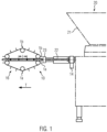
Figur 1Vorrichtung 10 zum Abteilen eines gefüllten Wurststrangs. -
Figur 2a -
Figur 2b -
Figur 3 -
Figur 4a -
Figur 4bFigur 4a -
Figur 4c zeigt eine Seitenansicht auf ein Verdrängerelement gemäß dem Ausführungsbeispiel inFigur 4a4b . -
Figur 4d zeigt eine Aufsicht auf das inFigur 4b -
Figur 5a -
Figur 5bFigur 5a -
Figur 5c zeigt eine Seitenansicht auf das Verdrängerelement wie es inFigur 5a5b gezeigt ist. -
Figur 6a -
Figur 6b -
Figur 6c zeigt eine Aufsicht auf ein Verdrängerelementepaar in der Abteilposition gemäß dem Stand der Technik. -
Figur 6d zeigt eine Seitenansicht auf das Verdrängerelement gemäß dem Stand der Technik -
Figur 7 -
Figur 8
-
Figure 1 shows a schematic representation of a filling machine with adevice 10 for dividing a filled sausage strand. -
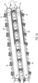
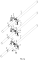
Figure 2a shows in perspective an embodiment according to the invention. -
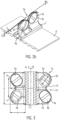
Figure 2b shows a perspective view of a displacement vane on a transport means according to a preferred embodiment. -
Figure 3 shows a side view of a displacement element according to an embodiment of the present invention. -
Figure 4a shows a pair of displacer elements according to a preferred embodiment in three different positions. -
Figure 4b shows a perspective view of theFigure 4a shown pair of displacer elements in greater detail. -
Figure 4c shows a side view of a displacement element according to the embodiment inFigure 4a and4b . -
Figure 4d shows a top view of theFigure 4b shown embodiment. -
Figure 5a shows another embodiment of a pair of displacer elements in three different positions. -
Figure 5b shows the displacer element pair of theFigure 5a shown embodiment in greater detail. -
Figure 5c shows a side view of the displacement element as it is inFigure 5a and5b is shown. -
Figure 6a shows a pair of displacer elements according to the state of the art. -
Figure 6b shows a top view of a pair of displacer elements according to the prior art. -
Figure 6c shows a top view of a pair of displacer elements in the compartment position according to the prior art. -
Figure 6d shows a side view of the displacement element according to the prior art -
Figure 7 shows a plan view of a pair of displacer elements in the compartment position according to the present invention -
Figure 8 shows a side view of a wing according to another embodiment of the present invention.
Durch das Füllrohr 22 wird die pastöse Masse in die z.B. auf dem Füllrohr 22 aufgezogene und durch die Darmbremse 23 gehaltene Hülle, z.B. den Darm, ausgestoßen, wodurch der gefüllte Wurststrang in bekannter Art und Weise erzeugt wird.The pasty mass is ejected through the filling
Unmittelbar hinter dem Füllrohr 22 befindet sich die Vorrichtung 10 zum Abteilen des gefüllten Wurststrangs. Der Wurststrang soll durch die Vorrichtung 10 in Einzelportionen von bestimmter Länge I unterteilt werden.The
Dazu ist mindestens ein Verdrängerelementepaar 1a, 1b vorgesehen. Bei dem in
Bei diesem Ausführungsbeispiel sind, wie nachfolgend noch näher erläutert, die Verdrängerelemente 1a, 1b auf dem umlaufenden Transportmittel, z.B. dem umlaufenden Transportband, Kette etc., in insbesondere gleichmäßigen Abständen angeordnet. Diese Ausführungsform wird nachfolgend noch unter Bezugnahme der
Der mindestens eine Verdrängerflügel 2a ist fahnenartig an einer Halterung 7 angeordnet, d.h., steht seitlich ab. Der jeweilige Verdrängerflügel kann sich in einer Richtung von der Halterung erstrecken die nicht der Radialrichtung entspricht. Entsprechendes ist vorteilhaft, damit sich die Verdrängerflügel in der Mittenebene überhaupt überlappen können.The at least one
Die Halterung 7 ist mit einem Drehmechanismus 15, der beispielsweise eine Antriebswelle aufweist, verbindbar um das jeweilige Verdrängerelement um eine Achse A1 zu drehen. Die Höhe des Verdrängerelements h liegt z.B. in einem Bereich von 20 mm bis 80 mm, insbesondere 30 mm bis 50 mm. Die Abmessung a vom oberen Punkt O der Aussparung 12 zum unteren Punkt U der Aussparung 12 liegt z.B. in einem Bereich von 15 mm bis 75 mm, insbesondere zwischen 25 mm und 45 mm. Die Tiefe t des Ausschnitts 12 liegt z.B. in einem Bereich von 5 mm bis 30 mm, insbesondere von 7 mm bis 25 mm. Die Erstreckung k des unteren und oberen Flügelabschnitts 3a, 4a nach außen liegt z.B. in einem Bereich von 30 mm bis 80 mm. Die Stärke der Flügel liegt z.B. in einem Bereich von 1 mm bis 6 mm, vorzugsweise von 1 mm bis 3 mm. Entsprechende Verdrängerelemente sind für Wurstkaliber in einem Bereich von 8 mm bis 60 mm geeignet. Die Erfindung ermöglicht auch die Verwendung der Verdrängerelemente im Zusammenhang mit Clipmaschinen, bei denen eben größere Wurstdurchmesser (z.B. bis 60 mm) verarbeitet werden.The
Sowohl der obere als auch der untere Flügelabschnitt 3a, 4a weisen seitlich gewölbte Taschen 5a, 6a auf, die ermöglichen, dass sich gegenüberliegende Verdrängerelemente ohne Kollision aneinander vorbei bewegen können, d.h., dass die äußersten Punkte O und U der Außenkontur bzw. der Verdrängerkanten 13 sich durch den durch die Taschen gebildeten Freiraum bewegen können.Both the upper and
Alternativ ist es auch möglich, statt der Taschen 5a,5b, 6a, 6b einfach eine Öffnung in der Fläche des oberen und unteren Flügelabschnitts innerhalb der Außenkontur der Flügel auszubilden. Dies ermöglicht ebenfalls, dass die Flügel sich problemlos aneinander vorbei bewegen können. Allerdings bringt die Lösung mit den Taschen eine verbesserte Stabilität mit sich und der Wurstrang kann beim Abteilen besser gestützt werden.Alternatively, instead of the
Im Zusammenhang mit
Bei diesem Ausführungsbeispiel ist im oberen Flügelabschnitt 3a, 3b eines jeweiligen Verdrängerelements 1a, 1b die gewölbte Tasche 5a, 5b zu einer ersten Seite, in
Die oberste Darstellung in
Auch eine nicht dargestellte Öffnung ist derart ausgebildet, dass dich die Verdrängerelemente entsprechend aneinander vorbeibewegen können.An opening (not shown) is also designed in such a way that the displacement elements can move past each other accordingly.
Der Abstand der Ebenen liegt auch hier z.B. insbesondere in einem Bereich vom Maß der Verdrängerflügeldicke im Bereich der Verdrängerkanten im sich erweiternden Bereich 12 zuzüglich +0 mm bis 4 mm, insbesondere 0,1 bis 3 mm, vorzugsweise 0,2 bis 1 mm, zumindest im Bereich der sich erweiternden Aussparung 12.Here too, the distance between the planes is, for example, in particular in a range of the dimension of the displacement vane thickness in the region of the displacement edges in the widening
Bei den in
Bei dem in den
Wie aus
Wie aus
Wie insbesondere aus
Die Flügel 2a, 2b greifen, wie in Zusammenhang mit den
Die Verdrängerelemente sind in den vorher gezeigten Ausführungsbeispielen derart ausgebildet, dass sich die Ausschnitte 12 insbesondere rautenförmig überlagern, derart, dass noch eine kleine Öffnung verbleibt, so dass der Wurststrang nicht abgeschert wird. Es ist aber auch möglich das Verdrängerelementepaar so ausbilden oder derart voneinander zu beabstanden, dass sich die Ausschnitte vollständig überlagern und der Wurststrang zur Erzeugung von Einzelwürsten durchtrennt wird. Dazu kann die Verdrängerkante von mindestens einem Verdrängerelement zumindest teilweise als Klinge ausgebildet sein oder eine Klinge aufweisen.In the previously shown embodiments, the displacement elements are designed such that the
Es können mehrere Flügel um den Umfang einer Halterung 7 eines Verdrängerelements angeordnet sein und mehrere Verdrängerelemente auf den umlaufenden Transportmitteln 8. Somit kann die Produktionsgeschwindigkeit gesteigert werden.Several wings can be arranged around the circumference of a
Die Vorrichtung weist weiter gemäß einer bevorzugten Ausführungsform eine Abdreheinrichtung 14 zum Drehen des zu befüllenden Wurststrangs 11 um seine Längsachse L auf und/oder z.B. in Transportrichtung nach den Verdrängerelementen 1a, 1b, eine Einrichtung zum Clippen oder eine Einrichtung zum Abbinden oder Verkleben oder Verschweißen des Wurststrangs nach dem Verdrängen.According to a preferred embodiment, the device further comprises a twisting
Die Erfindung stellt weiterhin die folgenden Ausführungsformen bereit:
- 1. Verdrängerelementepaar (1a, 1b) zum Abteilen eines zwischen den Verdrängerelementen (1a, 1b) transportierten Wurststrangs (11) in Einzelwürste, wobei jedes Verdrängerelement (1a, 1b) mindestens einen Flügel (2a, 2b) mit einem ersten Flügelabschnitt (3a, 3b) und einem zweiten Flügelabschnitt (4a, 4b) aufweist, zwischen denen ein sich nach außen erweiternder, insbesondere V-förmiger Ausschnitt (12) ausgebildet ist, dadurch gekennzeichnet, dass sowohl der erste als auch der zweite Flügelabschnitt (3a, b), (4a, b) eine zur Seite gewölbte Tasche (5a, 5b, 6a, 6b) oder eine Öffnung aufweist.
- 2. Verdrängerelementepaar (1a, 1b)
nach Ausführungsform 1, dadurch gekennzeichnet, dass die Verdrängerkanten (13) des ersten und zweiten Flügelabschnitts (2a, 2b), (3a, 3b) eines jeweiligen Verdrängerelements (1a, 1b) zumindest im Bereich des sich erweiternden Abschnitts (12) entweder- a) in im Wesentlichen parallelen Ebenen (E1, E2) oder
- b) in einer gemeinsamen Ebene (E1) liegen.
- 3. Verdrängerelementepaar nach Ausführungsform 2, dadurch gekennzeichnet, dass im Fall a) der Abstand der Ebenen voneinander vorzugsweise in einem Bereich liegt, der dem Maß der Dicke (s) der Flügelabschnitte +0 bis + 4 mm, insbesondere +0,1
mm bis 3 mm, liegt. - 4. Verdrängerelementepaar (1a, 1b) nach mindestens Ausführungsform 2, dadurch gekennzeichnet, dass im Fall a) im ersten Flügelanschnitt (3a, 3b) eines jeweiligen Verdrängerelements die gewölbte Tasche (5a, 5b) zu einer ersten Seite nach außen gewölbt ist und im zweiten Flügelabschnitt (4a, 4b) die gewölbte Tasche (6a, 6b) zur gegenüberliegenden Seite nach außen gewölbt ist und im Fall b) die gewölbten Taschen (5a, 5b, 6a, 6b) im ersten und zweiten Flügelabschnitt (3a, 3b, 4a, 4b) zur gleichen Seite gewölbt sind.
- 5. Verdrängerelementepaar (1a, 1b) nach mindestens einem der Ausführungsformen 1-4, dadurch gekennzeichnet, dass in einer Abteilposition, in der der Wurststrang (11) maximal eingeschnürt ist und die beiden sich erweiternden Ausschnitte (12) maximal überlagert sind, im Fall a) der Flügel (2a) des ersten Verdrängerelements (1a) und der Flügel (2b) des zweiten Verdrängerelements (1b) verschränkt ineinandergreifen können und im Fall b) die Flügel (2a, 2b) im Wesentlichen parallel nebeneinander angeordnet werden können.
- 6. Verdrängerelementepaar (1a, 1b), dadurch gekennzeichnet, dass die Flügel (2a, 2b) fahnenartig an einer Halterung (7) angeordnet sind, über die sie mit einem Drehmechanismus verbindbar sind, um die Verdrängerelemente (1a, 1b) um eine Achse (A1) zu drehen oder umlaufend um mehrere Achsen (A1, A2) zu bewegen.
- 7. Vorrichtung (10) zum Abteilen eines Wurststrangs (11) mit einem Verdrängerelementepaar (1a, 1b) nach mindestens einem der Ansprüche 1-6, mit einer Transporteinrichtung (16) zum Transportieren des gefüllten Wurststrangs (11) zwischen den gegenüberliegenden Verdrängerelementen (1a, 1b) und einen Drehmechanismus, um die Verdrängerelemente (1a, 1b) um eine jeweilige Drehachse (A1) zu drehen oder umlaufend um mehrere Drehachsen (A1, A2) zu bewegen.
- 8.
Vorrichtung nach Ausführungsform 7, dadurch gekennzeichnet, dass die Vorrichtung weiter eine Abdreheinrichtung (14) zum Drehen des zu befüllenden Wurststrangs (11) um seine Längsachse (L) aufweist und/oder die Vorrichtung eine Einrichtung zum Clippen oder eine Einrichtung zum Abbinden oder Verkleben oder Verschweißen des Wurststrangs nach dem Verdrängen aufweist. - 9.
Vorrichtung nach Ausführungsform 7oder 8, dadurch gekennzeichnet, dass die Verdrängerelemente (1a, 1b) derart angeordnet sind, dass in einer Abteilposition, in der die sich erweiternden Ausschnitte (12) der gegenüberliegenden Verdrängerelemente (1a, 1b) maximal überlagert sind, die jeweiligen Verdrängerkanten (13) des ersten Flügelabschnitts (3a, 3b), (4a, 4b) eines Verdrängerelements und des zweiten Flügelabschnitts (3a, 3b), (4a, 4b) des gegenüberliegenden Verdrängerelements zumindest im Bereich des jeweiligen sich erweiternden Ausschnitts (12) im Wesentlichen in parallelen Ebenen (Ea, Eb) liegen insbesondere die Ebenen maximal um 0 Grad bis ±5 Grad zueinander geneigt sind. - 10. Vorrichtung nach mindestens einer der
Ausführungsformen 7 bis 9, dadurch gekennzeichnet, dass die Verdrängerelemente (1a, 1b) um ihre Mittelachse (A1) gedreht werden können und die Mittelachse im Wesentlichen parallel zu den Ebenen (E1, E2) verläuft, in denen die Verdrängerkante (13) der Flügelabschnitte (3a, 3b), (4a, 4b) zumindest im Bereich des sich erweiternden Ausschnitts (12) liegt und vorzugsweise senkrecht zur Transportrichtung (T) läuft. - 11. Vorrichtung nach mindestens einer der Ausführungsformen 7-10, dadurch gekennzeichnet, dass die gegenüberliegenden Verdrängerelemente (1a, 1b) jeweils an zwei um mehrere Achsen (A1, A2) umlaufenden Transportmittel (8), insbesondere Transportkette oder Transportband, angeordnet sind und die Drehachsen (A1, A2) vorzugsweise im Wesentlichen parallel zu den Ebenen (E1, E2) verlaufen, in denen die Verdrängerkante der ersten und zweiten Flügelabschnitte im Bereich des Ausschnitts (12) angeordnet sind und vorzugsweise senkrecht zur Transportrichtung T verlaufen.
- 12. Vorrichtung nach mindestens einer der Ausführungsformen 7 -11, dadurch gekennzeichnet, dass ein Verdrängerelement (1a, 1b) mehrere umlaufende Flügel (2a, 2b) aufweist oder mehrere Verdrängerelemente (1a, 1b) mit einem jeweiligen Flügel (2a, 2b) auf dem jeweiligen umlaufenden Transportmittel (17) angeordnet sind.
- 13. Vorrichtung nach mindestens einer der Ausführungsformen 7 -12, dadurch gekennzeichnet, dass die Verdrängerelemente (1a, 1b) mittels 3-D-Druck oder Spritzguss hergestellt werden.
- 14. Vorrichtung
nach mindestens Ausführungsform 7, dadurch gekennzeichnet, dass zumindest im Bereich des sich insbesondere V-förmig erweiternden Ausschnitts (12) der Abstand zwischen der Ebene (E1), in der die Verdrängerkante (13) des ersten Flügelabschnitts (3a) liegt und der Ebene (E2), in der die Verdrängerkante des ersten Flügelabschnitts (3b) des gegenüberliegenden Verdrängerelements (1b) liegt und der Abstand zwischen der Ebene, in der die Verdrängerkante des zweiten Flügelabschnitts (4a) und der Ebene, in der die Verdrängerkante des zweiten Flügelabschnitts (4b) des gegenüberliegenden Verdrängerelements (1b) liegt, in einem Bereich liegt, der dem Maß der Verdrängerflügeldicke +0 mm bis +4 mm,insbesondere 0,1bis 3 mm liegt und vorzugsweise im Wesentlichen konstant ist. - 15. Verdrängerelementepaar nach mindestens einer der Ausführungsformen 1-6, dadurch gekennzeichnet, dass das Verdrängerelement aus einem Material aus der folgenden Gruppe gebildet ist: Kunststoff, Metall, insbesondere Edelstahl.
- 16. Verdrängerelementepaar nach mindestens einer der Ausführungsformen 1-6, dadurch gekennzeichnet, dass sich der mindestens eine Flügel (2a, 2b) nicht radial von einer Halterung (7), die sich um eine Achse dreht, erstreckt.
- 1. A pair of displacement elements (1a, 1b) for dividing a sausage strand (11) transported between the displacement elements (1a, 1b) into individual sausages, each displacement element (1a, 1b) having at least one wing (2a, 2b) with a first wing section (3a, 3b) and a second wing section (4a, 4b), between which an outwardly widening, in particular V-shaped, cutout (12) is formed, characterized in that both the first and the second wing section (3a, b), (4a, b) have a laterally curved pocket (5a, 5b, 6a, 6b) or an opening.
- 2. Displacement element pair (1a, 1b) according to
embodiment 1, characterized in that the displacement edges (13) of the first and second wing sections (2a, 2b), (3a, 3b) of a respective displacement element (1a, 1b) at least in the region of the widening section (12) either- a) in substantially parallel planes (E1, E2) or
- b) lie in a common plane (E1).
- 3. Displacement element pair according to embodiment 2, characterized in that in case a) the distance between the planes from one another is preferably in a range which corresponds to the thickness (s) of the wing sections +0 to +4 mm, in particular +0.1 mm to 3 mm.
- 4. Displacement element pair (1a, 1b) according to at least embodiment 2, characterized in that in case a) in the first wing section (3a, 3b) of a respective displacer element the curved pocket (5a, 5b) is curved outwards to a first side and in the second wing section (4a, 4b) the curved pocket (6a, 6b) is curved outwards to the opposite side and in case b) the curved pockets (5a, 5b, 6a, 6b) in the first and second wing section (3a, 3b, 4a, 4b) are curved to the same side.
- 5. Displacement element pair (1a, 1b) according to at least one of the embodiments 1-4, characterized in that in a compartmentalizing position in which the sausage strand (11) is maximally constricted and the two widening cutouts (12) are maximally superimposed, in case a) the wing (2a) of the first displacement element (1a) and the wing (2b) of the second displacement element (1b) can interlock and in case b) the wings (2a, 2b) can be arranged essentially parallel to one another.
- 6. Pair of displacement elements (1a, 1b), characterized in that the vanes (2a, 2b) are arranged in a flag-like manner on a holder (7), via which they can be connected to a rotating mechanism in order to rotate the displacement elements (1a, 1b) about an axis (A1) or to move them in rotation about several axes (A1, A2).
- 7. Device (10) for dividing a sausage strand (11) with a pair of displacement elements (1a, 1b) according to at least one of claims 1-6, with a transport device (16) for transporting the filled sausage strand (11) between the opposite displacement elements (1a, 1b) and a rotating mechanism to rotate the displacement elements (1a, 1b) about a respective axis of rotation (A1) or to move them in rotation about several axes of rotation (A1, A2).
- 8. Device according to
embodiment 7, characterized in that the device further comprises a twisting device (14) for rotating the sausage strand (11) to be filled about its longitudinal axis (L) and/or the device comprises a device for clipping or a device for tying or gluing or welding the sausage strand after displacement. - 9. Device according to
embodiment - 10. Device according to at least one of
embodiments 7 to 9, characterized in that the displacement elements (1a, 1b) can be rotated about their central axis (A1) and the central axis runs essentially parallel to the planes (E1, E2) in which the displacement edge (13) of the wing sections (3a, 3b), (4a, 4b) lies at least in the region of the widening cutout (12) and preferably runs perpendicular to the transport direction (T). - 11. Device according to at least one of embodiments 7-10, characterized in that the opposing displacement elements (1a, 1b) are each arranged on two transport means (8) rotating around a plurality of axes (A1, A2), in particular a transport chain or conveyor belt, and the axes of rotation (A1, A2) preferably run substantially parallel to the planes (E1, E2) in which the displacement edges of the first and second wing sections are arranged in the region of the cutout (12) and preferably run perpendicular to the transport direction T.
- 12. Device according to at least one of embodiments 7-11, characterized in that a displacement element (1a, 1b) has a plurality of rotating wings (2a, 2b) or a plurality of displacement elements (1a, 1b) with a respective wing (2a, 2b) are arranged on the respective rotating transport means (17).
- 13. Device according to at least one of embodiments 7-12, characterized in that the displacement elements (1a, 1b) are produced by means of 3D printing or injection molding.
- 14. Device according to at
least embodiment 7, characterized in that at least in the region of the cutout (12) which widens in particular in a V-shape, the distance between the plane (E1) in which the displacer edge (13) of the first wing section (3a) lies and the plane (E2) in which the displacer edge of the first wing section (3b) of the opposite displacer element (1b) lies and the distance between the plane in which the displacer edge of the second wing section (4a) and the plane in which the displacer edge of the second wing section (4b) of the opposite displacer element (1b) lies, lies in a range which corresponds to the dimension of the displacer wing thickness +0 mm to +4 mm, in particular 0.1 to 3 mm and is preferably substantially constant. - 15. Displacement element pair according to at least one of embodiments 1-6, characterized in that the displacer element is formed from a material from the following group: plastic, metal, in particular stainless steel.
- 16. Displacement element pair according to at least one of embodiments 1-6, characterized in that the at least one vane (2a, 2b) does not extend radially from a holder (7) which rotates about an axis.
Claims (16)
dadurch gekennzeichnet, dass
characterized in that
im ersten Flügelanschnitt (3a, 3b) eines jeweiligen Verdrängerelements die gewölbte Tasche (5a, 5b) zu einer ersten Seite nach außen gewölbt ist und im zweiten Flügelabschnitt (4a, 4b) die gewölbte Tasche (6a, 6b) zur gegenüberliegenden Seite nach außen gewölbt ist.Displacement element pair (1a, 1b) according to at least claim 1 or 2, characterized in that
in the first wing section (3a, 3b) of a respective displacement element, the curved pocket (5a, 5b) is curved outwards to a first side and in the second wing section (4a, 4b) the curved pocket (6a, 6b) is curved outwards to the opposite side.
der Flügel (2a) des ersten Verdrängerelements (1a) und der Flügel (2b) des zweiten Verdrängerelements (1b) verschränkt ineinandergreifen können.Pair of displacement elements (1a, 1b) according to at least one of claims 1-3, characterized in that in a compartmentalizing position in which the sausage strand (11) is maximally constricted and the two widening cutouts (12) are maximally superimposed,
the wing (2a) of the first displacement element (1a) and the wing (2b) of the second displacement element (1b) can interlock.
der Abstand zwischen der Ebene, in der die Verdrängerkante des zweiten Flügelabschnitts (4a) und der Ebene, in der die Verdrängerkante des zweiten Flügelabschnitts (4b) des gegenüberliegenden Verdrängerelements (1b) liegt, in einem Bereich liegt, der dem Maß der Verdrängerflügeldicke +0 mm bis +4 mm, insbesondere 0,1 bis 3 mm liegt und vorzugsweise im Wesentlichen konstant ist.Device according to at least claim 6, characterized in that at least in the region of the cutout (12) which widens in particular in a V-shape, the distance between the plane (E1) in which the displacement edge (13) of the first wing section (3a) lies and the plane (E2) in which the displacement edge of the first wing section (3b) of the opposite displacement element (1b) lies and
the distance between the plane in which the displacement edge of the second wing section (4a) and the plane in which the displacement edge of the second wing section (4b) of the opposite displacement element (1b) lies lies in a range which corresponds to the dimension of the displacement wing thickness +0 mm to +4 mm, in particular 0.1 to 3 mm and is preferably substantially constant.
Kunststoff, Metall, insbesondere Edelstahl.Displacement element pair according to at least one of claims 1-5, characterized in that the displacement element is formed from a material from the following group:
Plastic, metal, especially stainless steel.
Priority Applications (1)
| Application Number | Priority Date | Filing Date | Title |
|---|---|---|---|
| EP25178827.9A EP4581933A3 (en) | 2021-08-10 | 2021-08-10 | Pair of displacement elements |
Applications Claiming Priority (2)
| Application Number | Priority Date | Filing Date | Title |
|---|---|---|---|
| EP25178827.9A EP4581933A3 (en) | 2021-08-10 | 2021-08-10 | Pair of displacement elements |
| EP21190588.0A EP4133942B1 (en) | 2021-08-10 | 2021-08-10 | Displacement element pair |
Related Parent Applications (2)
| Application Number | Title | Priority Date | Filing Date |
|---|---|---|---|
| EP21190588.0A Division EP4133942B1 (en) | 2021-08-10 | 2021-08-10 | Displacement element pair |
| EP21190588.0A Division-Into EP4133942B1 (en) | 2021-08-10 | 2021-08-10 | Displacement element pair |
Publications (2)
| Publication Number | Publication Date |
|---|---|
| EP4581933A2 true EP4581933A2 (en) | 2025-07-09 |
| EP4581933A3 EP4581933A3 (en) | 2025-10-08 |
Family
ID=77274744
Family Applications (2)
| Application Number | Title | Priority Date | Filing Date |
|---|---|---|---|
| EP21190588.0A Active EP4133942B1 (en) | 2021-08-10 | 2021-08-10 | Displacement element pair |
| EP25178827.9A Pending EP4581933A3 (en) | 2021-08-10 | 2021-08-10 | Pair of displacement elements |
Family Applications Before (1)
| Application Number | Title | Priority Date | Filing Date |
|---|---|---|---|
| EP21190588.0A Active EP4133942B1 (en) | 2021-08-10 | 2021-08-10 | Displacement element pair |
Country Status (7)
| Country | Link |
|---|---|
| US (1) | US12004523B2 (en) |
| EP (2) | EP4133942B1 (en) |
| JP (1) | JP7413638B2 (en) |
| CN (2) | CN118575843A (en) |
| BR (1) | BR102022015228A2 (en) |
| ES (1) | ES3049113T3 (en) |
| PL (1) | PL4133942T3 (en) |
Families Citing this family (1)
| Publication number | Priority date | Publication date | Assignee | Title |
|---|---|---|---|---|
| EP4474296A1 (en) * | 2023-06-09 | 2024-12-11 | Albert Handtmann Maschinenfabrik GmbH & Co. KG | Device and method for producing bags filled with liquid or pasty filling material |
Family Cites Families (18)
| Publication number | Priority date | Publication date | Assignee | Title |
|---|---|---|---|---|
| US3264679A (en) * | 1963-12-24 | 1966-08-09 | Charles D Moekle | Apparatus for making linked products |
| US4418447A (en) * | 1981-07-02 | 1983-12-06 | Devro, Inc. | Method and apparatus for processing stuffed sausage casing |
| DE3401890A1 (en) * | 1984-01-20 | 1985-07-25 | Hoechst Ag, 6230 Frankfurt | USE OF A GATHERED HOSE |
| US4905349A (en) * | 1989-03-06 | 1990-03-06 | Townsend Engineering Company | Encased product and method for encasing the same |
| DE3911859A1 (en) * | 1989-04-11 | 1990-10-18 | Handtmann Albert Maschf | METHOD AND DEVICE FOR DIVIDING A CONTINUOUS SAUSAGE STRING COMING FROM A FILLING MACHINE INTO INDIVIDUAL SAUSAGES |
| DE9012339U1 (en) * | 1990-08-28 | 1991-04-25 | Albert Handtmann Maschinenfabrik GmbH & Co KG, 7950 Biberach | Device for dividing a continuous sausage strand coming from a filling machine into individual sausages |
| DE9012381U1 (en) * | 1990-08-29 | 1991-04-25 | Albert Handtmann Maschinenfabrik GmbH & Co KG, 7950 Biberach | Device for dividing a continuous sausage strand coming from a filling machine into individual sausages |
| FR2725876B1 (en) * | 1994-10-20 | 1997-01-17 | Nijal | MACHINE FOR PUTTING A FILLED HOSE IN THE FORM OF A TWISTED HOSE, IN PARTICULAR FOR THE SETTING OF SAUSAGE PORTIONS |
| US5709600A (en) * | 1996-03-27 | 1998-01-20 | Townsend Engineering Company | Method and means for linking and then separating encased sausage |
| DE19802101C1 (en) * | 1998-01-21 | 1999-08-26 | Handtmann Albert Maschf | Device and method for separating sausages |
| ES2299788T3 (en) * | 2004-12-14 | 2008-06-01 | ALBERT HANDTMANN MASCHINENFABRIK GMBH & CO. KG | CONFORMING DEVICE AND CONFORMING PROCEDURE FOR FORMING HEADS OF EXTREME EMBUTIDOS. |
| ATE419751T1 (en) * | 2006-09-19 | 2009-01-15 | Handtmann Albert Maschf | DEVICE AND METHOD FOR DIVISING A FILLED SAUSAGE STRAND |
| US7704131B1 (en) * | 2008-12-30 | 2010-04-27 | Kraft Foods Global Brands Llc | Apparatus for forming spaced intervals in a stuffed casing and method thereof |
| PL2213177T5 (en) * | 2009-01-28 | 2016-05-31 | Handtmann Albert Maschf | Device and method for separating filled sausage strands without damaging the casing |
| CN104229131A (en) | 2014-10-13 | 2014-12-24 | 新誉集团有限公司 | V-shaped eight-rotor aerial photography aircraft |
| WO2017081648A1 (en) * | 2015-11-13 | 2017-05-18 | Freddy Hirsch Group Ag | A sausage cutting apparatus |
| GB2560560B (en) * | 2017-03-15 | 2019-05-08 | Freddy Hirsch Group Pty Limited | A sausage cutting apparatus |
| DE102021112517B3 (en) * | 2021-05-12 | 2022-04-14 | Vemag Maschinenbau Gmbh | Separating device for separating portions from elongate casings filled with food mass, and the relevant method |
-
2021
- 2021-08-10 EP EP21190588.0A patent/EP4133942B1/en active Active
- 2021-08-10 EP EP25178827.9A patent/EP4581933A3/en active Pending
- 2021-08-10 PL PL21190588.0T patent/PL4133942T3/en unknown
- 2021-08-10 ES ES21190588T patent/ES3049113T3/en active Active
-
2022
- 2022-07-22 JP JP2022117343A patent/JP7413638B2/en active Active
- 2022-08-01 BR BR102022015228-4A patent/BR102022015228A2/en unknown
- 2022-08-04 CN CN202410843470.8A patent/CN118575843A/en active Pending
- 2022-08-04 CN CN202210932506.0A patent/CN115702649B/en active Active
- 2022-08-10 US US17/885,465 patent/US12004523B2/en active Active
Also Published As
| Publication number | Publication date |
|---|---|
| US20230047261A1 (en) | 2023-02-16 |
| JP7413638B2 (en) | 2024-01-16 |
| PL4133942T3 (en) | 2026-02-23 |
| CN115702649A (en) | 2023-02-17 |
| EP4133942B1 (en) | 2025-10-08 |
| US12004523B2 (en) | 2024-06-11 |
| EP4581933A3 (en) | 2025-10-08 |
| ES3049113T3 (en) | 2025-12-15 |
| EP4133942A1 (en) | 2023-02-15 |
| BR102022015228A2 (en) | 2023-03-07 |
| CN118575843A (en) | 2024-09-03 |
| EP4133942C0 (en) | 2025-10-08 |
| JP2023025680A (en) | 2023-02-22 |
| CN115702649B (en) | 2024-07-16 |
Similar Documents
| Publication | Publication Date | Title |
|---|---|---|
| EP0392083B1 (en) | Method of, and device for, dividing a string of sausages produced by a stuffing machine into single sausages | |
| EP1902622B1 (en) | Device and method for dividing a filled sausage strand | |
| EP0440039B1 (en) | Method and device for stuffing sausages in a string and for dividing into single sausages or into groups of connected sausages | |
| EP3458257B1 (en) | Device and method for compacting hollow articles by means of compression | |
| EP4088580A1 (en) | Portioning device and method as well as crimping element | |
| EP4133942B1 (en) | Displacement element pair | |
| EP0472825A1 (en) | Device for dividing a string of sausages produced by a stuffing machine, into single sausages | |
| EP4088581B1 (en) | Separating device for separating portions of elongated casings filled with food material and related method | |
| DE3702954A1 (en) | GROUPING DEVICE FOR THE FORMATION OF CONTAINER GROUPS | |
| EP3967146B1 (en) | Portioning device and method | |
| EP3449730B1 (en) | Device for dividing tubular casings | |
| DE2146554C3 (en) | Process and device for long rolling and / or long working of dough pieces Fr. Winkler KG, special factory for bakery machines and ovens, 7730 Villingen | |
| EP2213177B1 (en) | Device and method for separating filled sausage strands without damaging the casing | |
| DE102008039154A1 (en) | Snails sword Storage | |
| EP4014744A1 (en) | Device and method for linking and/or separating a sausage string | |
| DE102021125587B3 (en) | Device and method for aligning sausages | |
| EP1671546A1 (en) | Moulding apparatus and moulding method for moulding domes at the ends of sausages | |
| EP0474970A1 (en) | Device for dividing a string of sausages produced by a stoffing machine into single sausages | |
| EP4303141B1 (en) | Separating device for separating portions from elongated casings filled with food mass, corresponding crimping element and method | |
| AT503921B1 (en) | DEVICE FOR PROMOTING AND HANDING OBJECTS | |
| DE3408859A1 (en) | Sausage-filling machine with a device for forming the end and a cutting-off device for sausages | |
| DE102023108714A1 (en) | Process for the parallel production of shingled portions with different numbers of slices and a suitable slicing machine | |
| EP4603421A1 (en) | Transport device for transporting portions from elongated wrappers filled with food mass, corresponding separating device, method and use | |
| DE1075420B (en) | Device for deforming a material web of packaging material provided with undulating pockets |
Legal Events
| Date | Code | Title | Description |
|---|---|---|---|
| PUAI | Public reference made under article 153(3) epc to a published international application that has entered the european phase |
Free format text: ORIGINAL CODE: 0009012 |
|
| STAA | Information on the status of an ep patent application or granted ep patent |
Free format text: STATUS: THE APPLICATION HAS BEEN PUBLISHED |
|
| AC | Divisional application: reference to earlier application |
Ref document number: 4133942 Country of ref document: EP Kind code of ref document: P |
|
| AK | Designated contracting states |
Kind code of ref document: A2 Designated state(s): AL AT BE BG CH CY CZ DE DK EE ES FI FR GB GR HR HU IE IS IT LI LT LU LV MC MK MT NL NO PL PT RO RS SE SI SK SM TR |
|
| PUAL | Search report despatched |
Free format text: ORIGINAL CODE: 0009013 |
|
| AK | Designated contracting states |
Kind code of ref document: A3 Designated state(s): AL AT BE BG CH CY CZ DE DK EE ES FI FR GB GR HR HU IE IS IT LI LT LU LV MC MK MT NL NO PL PT RO RS SE SI SK SM TR |
|
| RIC1 | Information provided on ipc code assigned before grant |
Ipc: A22C 11/10 20060101AFI20250829BHEP |
|
| STAA | Information on the status of an ep patent application or granted ep patent |
Free format text: STATUS: REQUEST FOR EXAMINATION WAS MADE |