JP7413638B2 - displacement element pair - Google Patents
displacement element pair Download PDFInfo
- Publication number
- JP7413638B2 JP7413638B2 JP2022117343A JP2022117343A JP7413638B2 JP 7413638 B2 JP7413638 B2 JP 7413638B2 JP 2022117343 A JP2022117343 A JP 2022117343A JP 2022117343 A JP2022117343 A JP 2022117343A JP 7413638 B2 JP7413638 B2 JP 7413638B2
- Authority
- JP
- Japan
- Prior art keywords
- displacement
- wing
- displacement element
- plane
- wing section
- Prior art date
- Legal status (The legal status is an assumption and is not a legal conclusion. Google has not performed a legal analysis and makes no representation as to the accuracy of the status listed.)
- Active
Links
- 238000006073 displacement reaction Methods 0.000 title claims description 243
- 235000013580 sausages Nutrition 0.000 claims description 73
- 230000007246 mechanism Effects 0.000 claims description 9
- 229910052751 metal Inorganic materials 0.000 claims description 6
- 239000002184 metal Substances 0.000 claims description 5
- 229920003023 plastic Polymers 0.000 claims description 4
- 239000004033 plastic Substances 0.000 claims description 4
- 239000000463 material Substances 0.000 claims description 3
- 238000007789 sealing Methods 0.000 claims description 3
- 229910001220 stainless steel Inorganic materials 0.000 claims description 3
- 239000010935 stainless steel Substances 0.000 claims description 3
- 238000000034 method Methods 0.000 claims description 2
- 230000008569 process Effects 0.000 claims description 2
- 230000000452 restraining effect Effects 0.000 claims description 2
- 238000002347 injection Methods 0.000 claims 1
- 239000007924 injection Substances 0.000 claims 1
- 235000011837 pasties Nutrition 0.000 description 7
- 238000004519 manufacturing process Methods 0.000 description 5
- 230000011218 segmentation Effects 0.000 description 5
- 238000010146 3D printing Methods 0.000 description 4
- 230000015572 biosynthetic process Effects 0.000 description 4
- 208000031481 Pathologic Constriction Diseases 0.000 description 2
- 238000001746 injection moulding Methods 0.000 description 2
- 238000000638 solvent extraction Methods 0.000 description 2
- 208000037804 stenosis Diseases 0.000 description 2
- 230000036262 stenosis Effects 0.000 description 2
- 208000019300 CLIPPERS Diseases 0.000 description 1
- 208000021930 chronic lymphocytic inflammation with pontine perivascular enhancement responsive to steroids Diseases 0.000 description 1
- 238000010276 construction Methods 0.000 description 1
- 238000010586 diagram Methods 0.000 description 1
- 229910003460 diamond Inorganic materials 0.000 description 1
- 239000010432 diamond Substances 0.000 description 1
- 230000000694 effects Effects 0.000 description 1
- 239000012634 fragment Substances 0.000 description 1
- 235000013372 meat Nutrition 0.000 description 1
- 150000002739 metals Chemical class 0.000 description 1
- 238000005192 partition Methods 0.000 description 1
- 230000035515 penetration Effects 0.000 description 1
- 239000000243 solution Substances 0.000 description 1
- 230000007704 transition Effects 0.000 description 1
Images


Classifications
-
- A—HUMAN NECESSITIES
- A22—BUTCHERING; MEAT TREATMENT; PROCESSING POULTRY OR FISH
- A22C—PROCESSING MEAT, POULTRY, OR FISH
- A22C11/00—Sausage making ; Apparatus for handling or conveying sausage products during manufacture
- A22C11/006—Separating linked sausages
-
- A—HUMAN NECESSITIES
- A22—BUTCHERING; MEAT TREATMENT; PROCESSING POULTRY OR FISH
- A22C—PROCESSING MEAT, POULTRY, OR FISH
- A22C11/00—Sausage making ; Apparatus for handling or conveying sausage products during manufacture
- A22C11/10—Apparatus for twisting or linking sausages
- A22C11/107—A string passing between two rotary members comprising dividing elements cooperating with each other
-
- A—HUMAN NECESSITIES
- A22—BUTCHERING; MEAT TREATMENT; PROCESSING POULTRY OR FISH
- A22C—PROCESSING MEAT, POULTRY, OR FISH
- A22C11/00—Sausage making ; Apparatus for handling or conveying sausage products during manufacture
- A22C11/10—Apparatus for twisting or linking sausages
- A22C11/104—Apparatus for twisting or linking sausages by means of shear or blade elements
Description
本発明は、請求項1及び7の前文に係る変位要素対並びにそのような変位要素対によってソーセージストランドを区分する(divide)ための装置に関する。
The invention relates to a pair of displacement elements according to the preamble of
ソーセージを製造するために、ペースト状の塊が、例えば充填チューブを介してソーセージケーシング内に充填され、それにより、詰められたソーセージストランドが製造される。そのような「絶え間なく」充填されるソーセージストランドを充填中に等しい長さの部分に区分するために、製品ストランド内のペースト状の塊は、いわゆる向かい合う変位要素を利用して所定の間隔で変位され、特に狭窄点が形成される。この目的のために、充填されるべきソーセージストランドを、例えばねじりユニット(twist-offunit)によって、その長手方向軸を中心にねじることができ、それにより、ねじり点(twist-off unit)が狭窄点に入り込み(jump in)、したがって、ソーセージストランドが細分化される。現在市販されているタイプの変位要素を使用して製造が行なわれると、狭窄中に変位要素間に折り曲げ部が生じ、それらの折り曲げ部は、狭窄点のねじれ及びねじり点の入り込みを妨げることはできないが、それにもかかわらず、遅延を引き起こす場合があり、すなわち、ねじり点が後に入り込み、すなわち、搬送方向で見たときに、ねじり点が更に下流側にのみ入り込む。このことは、ねじり点又は区分点の形成により多くの時間がかかり、製品ケーシングがより多くの応力に晒されることを意味する。傷付き易いソーセージケーシングは変位中に損傷される場合があり、これは生産を著しく損なう。 To produce sausages, the pasty mass is filled into sausage casings, for example via filling tubes, thereby producing stuffed sausage strands. In order to divide such "continuously" filled sausage strands into equal length parts during filling, the pasty mass in the product strand is displaced at predetermined intervals with the help of so-called opposing displacement elements. In particular, narrowing points are formed. For this purpose, the sausage strand to be filled can be twisted about its longitudinal axis, for example by a twist-off unit, so that the twist-off unit is at the constriction point. jump in and thus fragment the sausage strands. When manufacturing is carried out using displacement elements of the type currently available on the market, folds occur between the displacement elements during stenosis, and these folds do not prevent twisting of the stenosis point and penetration of the torsion point. However, it may nevertheless cause a delay, i.e. the torsion point enters later, i.e. the torsion point only enters further downstream when viewed in the conveying direction. This means that the formation of twist points or break points takes more time and the product casing is exposed to more stress. Fragile sausage casings can be damaged during displacement, which significantly impairs production.
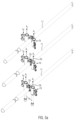
図6aは、従来技術に係る2つの向かい合う変位要素を斜視図で示し、これらの向かい合う変位要素は、それらのそれぞれの軸線Aを中心に反対方向に回転される。ソーセージストランドは変位要素間を通過する。図6a及び図6bから分かるように、各変位要素は、図6bに示すように区分位置で互いに係合する上側ウイングセクション及び下側ウイングセクションを伴う少なくとも1つのウイングを有する。図6b及び図6dから分かるように、それぞれの向かい合う上側ウイングセクション及びそれぞれの向かい合う下側ウイングセクションは、その後、互いに対して例えば20°の2倍の角度で延びている。図6cから分かるように、これは、ウイングセクションの2つの上面間に及び2つの下面間にも、ソーセージストランドが折り曲げ部で広がることによってソーセージケーシングのねじれを減速させるそれぞれの領域が形成されるという効果を有する。それぞれのウイングセクションは、変位要素を互いに可能な限り近くに位置させることができるようにするべく、互いに対して角度を成して延びているが、それにもかかわらず、ウイングセクションは、衝突することなく互いに通り過ぎることができる。 FIG. 6a shows in a perspective view two opposing displacement elements according to the prior art, which are rotated in opposite directions about their respective axis A. The sausage strands pass between the displacement elements. As can be seen in Figures 6a and 6b, each displacement element has at least one wing with an upper wing section and a lower wing section engaging each other in the segmented position as shown in Figure 6b. As can be seen in Figures 6b and 6d, each opposing upper wing section and each opposing lower wing section then extend at twice the angle, for example 20[deg.], with respect to each other. As can be seen in Figure 6c, this means that between the two upper surfaces and also between the two lower surfaces of the wing sections, respective regions are formed in which the sausage strands spread out at the bend, thereby slowing down the torsion of the sausage casing. have an effect. Although each wing section extends at an angle with respect to each other in order to allow the displacement elements to be located as close as possible to each other, the wing sections nevertheless do not collide. They can pass each other without any problems.
これを基礎として、本発明の目的は、区分点が迅速に且つ穏やかに入り込むことができるようにする、ソーセージストランドを区分するための装置のための改良された変位要素を提供することである。 On this basis, the object of the invention is to provide an improved displacement element for a device for sectioning sausage strands, which allows the sectioning point to enter quickly and gently.
本発明によれば、この目的は、請求項1の特徴によって達成される。
According to the invention, this object is achieved by the features of
本発明によれば、変位要素間で搬送されるソーセージストランドを個々のソーセージに区分するための変位要素対が提供される。各変位要素は、第1のウイングセクション及び第2のウイングセクションを有する少なくとも1つのウイングセクションを有し、第1のウイングセクションと第2のウイングセクションとの間に、外側に広がる、特にV字形の切り欠きが形成されている。第1のウイングセクション、すなわち、例えば上側ウイングセクション、及び、第2のウイングセクション、例えば下側ウイングセクションはいずれも、横方向に湾曲したポケット又は開口を有する。 According to the invention, a pair of displacement elements is provided for dividing the sausage strands conveyed between the displacement elements into individual sausages. Each displacement element has at least one wing section with a first wing section and a second wing section, and between the first wing section and the second wing section an outwardly extending, in particular V-shaped A notch is formed. The first wing section, eg, the upper wing section, and the second wing section, eg, the lower wing section, both have laterally curved pockets or openings.
それぞれのウイングセクションの外側輪郭内の領域にそれぞれが配置される湾曲ポケット又は開口は、例えば第1のウイングセクションが向かい合う変位要素のそれぞれのウイングセクションの湾曲したポケットの領域を通過することができる、すなわち、ポケット又は開口によって形成される自由空間を通って移動することができるため、ウイングセクションが回転中に衝突しないように変位要素が互いに通過できるようにする。したがって、ソーセージストランドが最大限に収縮されて2つの広がる、特にV字形の切り欠きが最大限に重なり合う区分位置において、それぞれの変位要素の第1及び第2のウイングセクションをそれらの間の距離が小さい状態で互いに略平行に配置することができ、それにより、ウイングセクションの表面間での折り曲げ部の形成を防止することができ、ねじり点がより迅速に且つより緩やかに入り込むことができる。 Curved pockets or apertures, each arranged in an area within the outer contour of the respective wing section, may for example allow the first wing section to pass through the area of the curved pocket of the respective wing section of the opposing displacement element. That is, they can be moved through the free space formed by the pockets or openings, thus allowing the displacement elements to pass through each other so that the wing sections do not collide during rotation. Therefore, in the segmentation position where the sausage strand is maximally contracted and the two widening, in particular V-shaped notches overlap maximally, the first and second wing sections of the respective displacement element are arranged such that the distance between them is They can be arranged substantially parallel to each other in a small state, thereby preventing the formation of folds between the surfaces of the wing sections and allowing the torsion points to enter more quickly and more gently.
好ましい実施形態によれば、変位エッジ、すなわち、それぞれの変位要素の第1及び第2のウイングセクションの外側輪郭は、少なくとも広がる切り欠きの領域で、a)略平行な平面又はb)共通の平面のいずれかに配置される。第1及び第2のウイングセクションの変位エッジが平行な平面に配置される場合、ウイングは、ソーセージストランドを区分するように互いに係合することができる。第1及び第2のウイングセクションの変位エッジが共通の平面に配置される場合、区分は、互いに平行に方向付けられたウイングによって達成され得る。この場合、それぞれの平面は、特に、広がりセクションの領域におけるウイング幅の中央を通って延びている。 According to a preferred embodiment, the displacement edges, i.e. the outer contours of the first and second wing sections of the respective displacement element, at least in the region of the widening notch, are in a) substantially parallel planes or b) a common plane. be placed in one of the following. If the displaced edges of the first and second wing sections are arranged in parallel planes, the wings can engage each other to partition the sausage strands. If the displacement edges of the first and second wing sections are arranged in a common plane, the division can be achieved by wings oriented parallel to each other. In this case, the respective plane extends in particular through the middle of the wing width in the region of the flared section.
この配置は、少なくとも外側に広がる、特にV字形のセクションの領域において、区分位置で向かい合う変位要素のウイング間の距離を小さく保つことができるようにする。ここで、距離は略一定であってもよい。ウイングセクションは従来技術のように分岐しないため、折り曲げ部の形成を効果的に防止することができ、その結果、ソーセージストランドは、ねじりプロセス中に可能な限り最短の時間でねじれ、ねじり点が入り込む。したがって、全体として、区分点がより緩やかに生成される。 This arrangement makes it possible, at least in the region of the outwardly extending, in particular V-shaped section, to keep the distance between the wings of the displacing elements facing each other in the sectioning position small. Here, the distance may be substantially constant. Since the wing sections do not branch like in the prior art, the formation of folds can be effectively prevented, so that the sausage strands are twisted in the shortest possible time during the twisting process, and the twist points enter . Therefore, overall, the segmentation points are generated more slowly.
ウイング要素の厚さに応じて、平面間の距離は、好ましくは以下の範囲内、すなわち、ウイングセクションの厚さの大きさ+0mm~4mm、特に厚さの大きさ+0.1mm~3mm、特に+0.2mm~1mmの範囲内にある。この範囲では、詰まりがなく、ねじり点が迅速に且つ完全に入り込む。ここで考慮されるのは、広がる切り欠き内のウイングセクションの厚さ、特に最大厚さ(一定でない厚さの場合)である。 Depending on the thickness of the wing element, the distance between the planes is preferably in the following range: the magnitude of the thickness of the wing section +0 mm to 4 mm, in particular the magnitude of the thickness +0.1 mm to 3 mm, especially +0 It is within the range of .2 mm to 1 mm. In this range there is no blockage and the torsion point enters quickly and completely. What is taken into consideration here is the thickness of the wing section within the widening cutout, in particular the maximum thickness (in case of non-constant thickness).
好適には、ケースa)では、湾曲したポケットが、それぞれの変位要素の第1のウイングセクションにおいて第1の側に向かって外側に湾曲しており、湾曲したポケットは、第2のウイングセクションにおいて反対側に向かって湾曲しており、ケースb)では、第1及び第2のウイングセクションの湾曲したポケットが、同じ側に湾曲している。したがって、ウイングセクションは、衝突することなく互いに通り過ぎることができる。 Preferably, in case a), the curved pocket is curved outwardly towards the first side in the first wing section of the respective displacement element, and the curved pocket is curved outwardly towards the first side in the first wing section of the respective displacement element. In case b) the curved pockets of the first and second wing sections are curved towards the same side. The wing sections can therefore pass each other without colliding.
好ましい実施形態によれば、ソーセージストランドが最大限に収縮され、2つの広がりセクションが最大限に重なり合う区分位置において、第1の変位要素のウイングと第2の変位要素のウイングとを互いに係合させてもよく、又は、ウイングを略平行に並んで配置してもよい。 According to a preferred embodiment, the wings of the first displacement element and the wings of the second displacement element are brought into engagement with each other in the segmentation position, where the sausage strand is maximally contracted and the two flared sections overlap maximally. Alternatively, the wings may be arranged substantially parallel to each other.
好ましい実施形態によれば、ウイングは、ホルダ上に旗状の態様で配置されてもよく、ホルダを介して、ウイングは、変位要素を軸線を中心に回転させるための又は変位要素が複数の軸線の周りで循環するように変位要素を移動させるための特に駆動シャフトを含む回転機構に接続可能である。このことは、変位要素が例えばそれらの中心軸線を中心に互いに離間した関係で回転される又は変位要素が搬送ユニット、例えばチェーン又はコンベヤベルトなどに固定されて循環することを意味する。 According to a preferred embodiment, the wings may be arranged in a flag-like manner on the holder, through which the wings can be arranged for rotating the displacement element around an axis or for rotating the displacement element around a plurality of axes. is connectable to a rotation mechanism, in particular including a drive shaft, for moving the displacement element in circulation around the drive shaft. This means, for example, that the displacement elements are rotated in spaced relation to each other about their central axes, or that the displacement elements are fixed to a transport unit, such as a chain or a conveyor belt, and circulate.
本発明に係る変位要素は、それらが回転されても又は循環しても、互いに向かって直線的に移動され、そのウイングセクションを区分位置で互いに非常に近接して配置できる変位要素と同じ利点を有する。しかしながら、回転動作又は循環動作は、本発明に係る生産速度の増大を可能にする。 The displacement elements according to the invention, whether they are rotated or circulated, have the same advantages as displacement elements which can be moved linearly towards each other and whose wing sections can be placed very close to each other in segmented positions. have However, a rotary or circular motion allows for increased production rates according to the invention.
ソーセージストランドを区分するための装置は、請求項1~6の少なくとも一項に記載の少なくとも1つの変位要素対を備える。更に、装置は、詰められたソーセージストランドを向かい合う変位要素間で搬送するための搬送装置を備える。更に、装置は、変位要素をそれぞれの回転軸線を中心に回転させるための又は変位要素が複数の回転軸線の周りで循環するように変位要素を移動させるための回転機構を備える。
The device for sectioning sausage strands comprises at least one pair of displacement elements according to at least one of
変位要素は、ねじりデバイスが設けられない場合でもペースト状の塊を変位させることができるが、ソーセージストランドをその長手方向軸線Lを中心に回転させるためのねじりデバイスが有利であり、それにより、個々のソーセージ間にねじり点を形成することができる。共押し出しされたソーセージの場合、例えば、ソーセージケーシングがペースト状の塊と共に押し出される場合には、ねじりデバイスが不要である。ここでも、本発明は、斜め圧搾を伴うことなく良好に形成された区分点を生成できるようにするため、有利である。 Although the displacement element can displace the pasty mass even if no twisting device is provided, a twisting device for rotating the sausage strands about their longitudinal axis L is advantageous, so that the individual Twisting points can be formed between the sausages. In the case of co-extruded sausages, for example when the sausage casing is extruded together with a pasty mass, no twisting device is required. Again, the invention is advantageous because it allows well-formed segmentation points to be produced without oblique squeezing.
好ましい実施形態によれば、変位要素は、向かい合う変位要素の広がる切り欠きが最大限に重なり合う区分位置において、変位要素の第1のウイングセクション及び対向する変位要素の第2のウイングセクションのそれぞれの変位エッジが少なくともそれぞれの広がる切り欠きの領域で、略平行な平面内に配置されるように配置されている。略平行とは、最大偏差が例えば0°~±10°、特に0°~5°、更により好ましくは0°~3°であることを意味する。 According to a preferred embodiment, the displacement element is configured to reduce the displacement of each of the first wing section of the displacement element and the second wing section of the opposite displacement element in a segmented position where the widening notches of the opposite displacement elements overlap to the greatest extent possible. The edges are arranged such that at least in the area of each widening notch they are arranged in substantially parallel planes. Substantially parallel means that the maximum deviation is for example from 0° to ±10°, in particular from 0° to 5°, even more preferably from 0° to 3°.
変位要素は、ここでは、回転機構を介してそれらの中心軸線A1を中心に回転することができ、中心軸線は、例えば、平面E1,E2と略平行に延びており、ウイングセクションのそれぞれの変位エッジは、少なくとも広がる切り欠きの領域に配置される。好ましくは、中心軸線又は回転軸線は、ソーセージストランドの搬送方向Tに対して垂直に延びている。 The displacement elements can here be rotated about their central axis A1 via a rotation mechanism, which central axis extends, for example, approximately parallel to the planes E1, E2, and the respective displacements of the wing sections The edge is arranged at least in the region of the widening cutout. Preferably, the central axis or axis of rotation extends perpendicularly to the conveying direction T of the sausage strands.
好ましい実施形態によれば、それぞれの向かい合う変位要素は、2つ以上の軸線の周りで循環する2つの搬送ユニット上に、特に搬送チェーン上又はコンベヤベルト上に配置される。回転軸線は、好ましくは、平面と略平行に延びており、第1及び第2のウイングセクションの変位エッジは、特にV字形である切り欠きの領域に配置される。回転軸線は、好ましくは、ソーセージストランドの搬送方向に対して垂直に延びる。 According to a preferred embodiment, each opposing displacement element is arranged on two transport units circulating around two or more axes, in particular on a transport chain or on a conveyor belt. The axis of rotation preferably extends substantially parallel to the plane, and the displacement edges of the first and second wing sections are arranged in the region of the cutout, which is in particular V-shaped. The axis of rotation preferably extends perpendicular to the conveying direction of the sausage strands.
更なる実施形態によれば、1つの変位要素が複数の循環ウイングを有し、又は、複数の変位要素が、それぞれの循環搬送ユニット上に配置されたそれぞれのウイングを有する。このようにして、スループットを高めることができる。 According to a further embodiment, a displacement element has a plurality of circulation wings, or a plurality of displacement elements has a respective wing arranged on a respective circulation transport unit. In this way, throughput can be increased.
好適には、変位要素は、3D印刷又は射出成形によって製造されている。変位要素を形成するためのシートメタルの使用から離れることにより、この時点で、新たな形状及び輪郭を想定し得る。従来技術では、プラスチックから形成される変位要素が既に存在していたが、それらの形状はシートメタル要素の輪郭に類似していた。3D印刷の使用は、特に簡単な態様で、本発明に係るポケット又は開口を有する変位要素を製造できるようにする。しかしながら、金属から形成される変位要素も3D印刷によって製造することができる。 Preferably, the displacement element is manufactured by 3D printing or injection molding. By moving away from the use of sheet metal to form displacement elements, new shapes and contours can now be envisaged. In the prior art, displacement elements made of plastic already existed, but their shape resembled the contours of sheet metal elements. The use of 3D printing makes it possible to manufacture displacement elements with pockets or openings according to the invention in a particularly simple manner. However, displacement elements formed from metal can also be manufactured by 3D printing.
変位要素対は、例えば、以下のグループ、すなわち、
プラスチック、金属、特にステンレス鋼
のうちの材料から形成されてもよい。
The displacement element pairs may be, for example, the following groups:
It may also be formed from materials such as plastic, metal and especially stainless steel.
特に好ましい実施形態によれば、少なくとも特にV字形に広がる切り欠きの領域において、第1のウイングセクションの変位エッジが配置される平面と対向する変位要素の第1のウイングセクションの外側輪郭が配置される平面との間の距離、及び、第2のウイングセクションの変位エッジが配置される平面と対向する変位要素の第2のウイングセクションの変位エッジが配置される平面との間の距離は、ウイングセクションの厚さ以上であり、特に、所定の範囲、すなわち、変位ウイング厚+0mm~4mmの大きさ、特に厚さ+0.1mm~3mmの大きさ、特に0.2mm~1mmの範囲内にある。ここで考慮されるのは、厚さ、特に広がる切り欠き内のウイングセクションの最大厚さである。 According to a particularly preferred embodiment, the outer contour of the first wing section of the displacement element is arranged, at least in the region of the V-shaped widening cutout, opposite the plane in which the displacement edge of the first wing section is arranged. and the distance between the plane in which the displacement edge of the second wing section is arranged and the plane in which the displacement edge of the second wing section of the opposing displacement element is arranged. The thickness of the section is greater than or equal to the thickness of the section, in particular within a predetermined range, namely the displacement wing thickness + 0 mm to 4 mm, in particular the thickness + 0.1 mm to 3 mm, in particular 0.2 mm to 1 mm. What is taken into consideration here is the thickness, in particular the maximum thickness of the wing section within the widening cutout.
搬送方向で見て、変位エッジ間の距離を適切に小さく保つことができる場合には、向かい合う変位要素のウイングセクションが互いに近接して配置されるため、区分点は非常にうまく入り込むことができ、折り曲げ部が生じない。 If the distance between the displacement edges, viewed in the conveying direction, can be kept suitably small, the wing sections of opposing displacement elements are arranged close to each other, so that the dividing points can penetrate very well, No bends occur.
好ましい実施形態によれば、少なくとも1つのウイングは、軸線を中心に回転するホルダから径方向に延びていない。したがって、向かい合うウイングは、互いに容易に通過することができる。 According to a preferred embodiment, the at least one wing does not extend radially from the holder rotating about the axis. Opposing wings can therefore easily pass each other.
以下では、以下の図を参照して、本発明を更に詳しく説明する。 In the following, the invention will be explained in more detail with reference to the following figures.
図1は、詰められたソーセージストランドを製造するための充填機20の一例を概略図で示し、ソーセージストランドは、本発明に係る装置10を利用して、所定の長さを有する個々のソーセージストランドセクションに区分される。充填機20には既知の態様で充填ホッパ21が設けられ、この充填ホッパ21を介して、ペースト状の塊、例えばソーセージ肉が、図示しない供給システムを介して充填チューブ22に充填されて押し込まれる。ケーシングブレーキ23が例えば充填チューブの端部に配置される。詰まったソーセージストランドをねじり切るために、ここでは、モータを介して駆動されるねじりユニット14、特にねじりギアユニットが任意選択的に設けられる。ねじりユニット14によって、充填チューブ22をその上に設置されたケーシングと共に長手方向軸線Lを中心に回転することができる。
FIG. 1 schematically shows an example of a filling
充填チューブ22を通じて、ペースト状の塊は、ケーシング、例えば、充填チューブ22上に設置されてケーシングブレーキ23によって保持されるソーセージスキン内に吐出され、それにより、詰められたソーセージストランドが既知の態様で製造される。
Through the filling
充填チューブ22の直ぐ下流側には、詰められたソーセージストランドを区分するための装置10が設けられる。ソーセージストランドは、装置10によって特定の長さlの個々の部分に区分されるようになっている。
Immediately downstream of the filling
この目的のため、少なくとも1つの変位要素対1a,1bが設けられる。図1に示される実施形態では、1つの典型的な搬送デバイス16のみが示され、この搬送デバイスは向かい合う循環搬送ユニット、例えばコンベヤベルト又はコンベヤチェーンなどを備え、これらの間に詰められたソーセージストランド11が搬送される。
For this purpose, at least one
実施形態では、以下でより詳細に説明するように、変位要素1a,1bは、循環搬送ユニット、例えば循環コンベヤベルト、チェーンなどに、互いから一定の距離、特に均一な距離を隔てて配置される。この実施形態は、図2a及び図2bを参照して以下により詳細に説明される。
In an embodiment, as will be explained in more detail below, the
図3は、本発明の一実施形態に係る変位要素を概略的に示す。変位要素は、上側すなわち第1のウイングセクション3aと、下側すなわち第2のウイングセクション4aとを備える少なくとも1つのウイング2aを有する。2つのウイングセクション間には、外側に広がる、特にエッジ側で開いたV字形の切り欠き12が設けられる。V字形の切り欠き12の領域には、変位エッジ13が配置される。
FIG. 3 schematically depicts a displacement element according to an embodiment of the invention. The displacement element has at least one
少なくとも1つの変位ウイング2aは、ホルダ7上に旗状の態様で配置され、すなわち、ホルダ7から横方向に突出する。それぞれの変位ウイングは、径方向に対応しない方向でホルダから延びてもよい。これは、変位ウイングが実際に中心平面で重なり合うことができるように有利である。
At least one
ホルダ7は、それぞれの変位要素を軸線A1を中心に回転させるための例えば駆動シャフトを有する回転機構15に接続されるようになっている。変位要素の高さhは、例えば20mm~80mm、特に30mm~50mmの範囲である。切り欠き12の上側点Oから切り欠き12の下側点Uまでの寸法aは、例えば15mm~75mmの範囲、特に25mm~45mmの範囲である。切り欠き12の深さtは、例えば、5mm~30mm、特に7mm~25mmの範囲である。下側ウイングセクション3a及び上側ウイングセクション4aの外側に延びた部分kは、例えば、30mm~80mmの範囲である。ウイングの厚さは、例えば、1mm~6mm、好ましくは1mm~3mmの範囲である。この種の変位要素は、8mm~60mmの範囲のソーセージ内径に適している。また、本発明は、処理されるソーセージ直径が実際にはより大きい(例えば、最大60mm)場合に、クリッパに関連する変位要素の使用も可能にする。
The
上側ウイングセクション3a及び下側ウイングセクション4aはいずれも、向かい合う変位要素が衝突することなく互いに通過できるようにする横方向に湾曲したポケット5a,6aを有し、すなわち、外側輪郭及び変位エッジ13の最も外側の点O,Uはそれぞれ、ポケットによって画定される自由空間を通じて移動することができる。
Both the
或いは、ポケット5a,5b,6a,6bの代わりに、ウイングの外側輪郭内の上側ウイングセクション及び下側ウイングセクションの表面に開口を単に形成することも想定し得る。また、これにより、ウイングが互いに容易に通り過ぎることが可能になる。しかしながら、ポケットを利用する解決策は、改善された安定性を更に与え、ソーセージストランドを区分中により良好に支持できる。
Alternatively, instead of
ここで、図4a~図4dに関連して、変位要素の第1の実施形態について説明し、その場合、上下に(又は横方向に並んで)配置されるウイングセクション3a,4aは、平行な平面E1,E2で互いにずらして配置される。これは、特に図4cの側面図で見ることができる。上側ウイングセクション3aの変位エッジ13は第1の平面E1に配置され、下側ウイングセクション4aの変位エッジは、平面E1と平行な第2の平面E2に配置され、平面E1,E2は、広がりセクション12における変位エッジの領域の変位ウイング厚(厚さが一定でない場合には、最大厚さが考慮される)に依存する範囲内にある距離sで延びており、距離s=変位ウイング厚+0mm~4mm、特に+0.1mm~3mm、更により好ましくは+0.2mm~1mmである。ウイングセクション3a,4aは、移行領域において互いに隣接している。平面E1,E2は、好ましくは回転軸線と平行であり、特に回転軸線A1に沿うベクトルと回転軸線A1に対して垂直なベクトルとによって画定される平面と平行である。
A first embodiment of a displacement element will now be described in connection with FIGS. 4a to 4d, in which
この実施形態において、湾曲したポケット5a,5bは、それぞれの変位要素1a,1bの上側ウイングセクション3a,3bにおいて、第1の側に向けて、図4cでは左側に向けて外側に湾曲する。下側ウイングセクション4a、4bでは、ポケット6a、6bが反対側に湾曲する。図4dは、ポケット5aの断面を示す。湾曲は、ウイングが衝突することなく互いに通り過ぎることができるように自由空間を作り出す。図4に示される実施形態では、向かい合う変位要素1a,1bの上側(第1の)及び下側(第2の)ウイングセクション3a,3b,4a,4bが互いに係合する。このことは、ソーセージストランド11が最大限に収縮されてここではV字形に広がる2つのセクション12が最大限に重なり合う区分位置において、第1の変位要素の上側ウイングセクション3a及び第2の変位要素の下側ウイングセクション4bが平面E1に配置され、第2の変位要素の上側ウイングセクション3b及び第2の変位要素の下側ウイングセクション4aが平面E2に配置されることを意味する。そのような区分位置が図4aの最も下側の図に示される。
In this embodiment, the
図4aの最も上側の図は、変位要素が矢印の方向でそれぞれの軸線A1を中心に回転し、入ってくるソーセージストランド11を区分してペースト状の塊を変位させ始める様子を示している。ポケットは、ウイングが互いに阻止することなく通過できるようにし、例えば50mm~150mmの2つの回転軸線間の距離を実現することができる。ウイング2a,2bは、図4aの最も下側の図に見られるように、区分位置に達するまで互いに向かって移動する。充填されるべきソーセージストランド11がねじりユニットによってねじられると、その時点でねじり点30が入り込むことができ、ソーセージが区分される。その後、ウイング2a,2bが再び矢印の方向に離れる。ポケット5a,5b,6a,6bは、ウイング2a,2bが衝突することなく再び離れることができるようにする。駆動は、この場合には従動シャフト16を介してホルダ7に接続可能な回転機構15によって行なわれる。ポケットpの深さは、駆動シャフトの中心距離及び変位要素の構造形態によってもたらされる。ポケットは、横方向外側に膨出し、例えば、略楕円形の形状であってもよい。
The topmost view of FIG. 4a shows how the displacement elements rotate about their respective axes A1 in the direction of the arrows and begin to segment the
また、図示されていない開口も、変位要素がそれに応じて互いに通過することができるように構成される。 Openings, not shown, are also arranged in such a way that the displacement elements can pass through each other accordingly.
図5cは、少なくとも広がりセクション12の領域においてそれぞれの変位要素の上側及び下側ウイングセクション3a,3b,4a,4bの変位エッジ13が共通の平面E1に配置される、すなわち、互いにずらして配置されないことを除き、図4に関連して示される実施形態に本質的に対応する更なる実施形態を示す。残りに関して、この実施形態は、図4aに関連して示される実施形態に対応する。ソーセージストランド11が最大限に収縮されて2つの広がる切り欠き12が最大限に重ね合わされる区分位置において、ウイング2a,2bは、ここでは、図5aの最も下側の図から分かるように、略平行に並んで配置される。この場合も、開口及びポケット5a,5b,6a,6bはそれぞれ、ウイングが衝突することなく互いに通り過ぎることができるようにする。区分位置では、例えば、第1の変位要素の上側及び下側ウイングセクション3a,4aが平面Eaに配置され、第2の変位要素2bの上側ウイングセクション4a及び下側ウイングセクション4bが平面Eaと平行な平面Ebに配置され、これらの平面は、前述したように、回転軸線A1に沿うベクトルと回転軸線A1に対して垂直なベクトルとによって画定される平面と平行である。
FIG. 5c shows that the displacement edges 13 of the upper and
また、平面間の距離は、ここでは、例えば、特に、少なくとも広がり開口12の領域において、広がり領域12における変位エッジの領域の変位ウイング厚の寸法+0mm~4mm、特に0.1mm~3mm、好ましくは0.2mm~1mmに対応する範囲にある。
The distance between the planes is here, for example, in particular at least in the region of the flared
図5bは、ウイング2a,2bが互いに向かってどのように移動することができるかを詳細に示す。
Figure 5b shows in detail how the
図4a及び図5aに示されるソーセージストランドを区分するための装置の場合、ソーセージストランドは、例えば2つの向かい合うコンベヤベルトによって、図示されていない搬送装置を介して搬送方向Tに搬送される。 In the case of the device for sorting sausage strands shown in FIGS. 4a and 5a, the sausage strands are conveyed in the conveying direction T via a conveying device (not shown), for example by two opposing conveyor belts.
図4及び図5に示される実施形態の場合、変位要素はそれぞれ、軸線A1、特に中心軸線を中心に旋回する、すなわち、変位要素が回転する。しかしながら、変位要素は、特に図2a及び図2bから分かるように、複数の回転軸線A1,A2の周りで循環するように移動されてもよい。変位ベルトは、図2aのように上下に配置されてもよいが、2つの変位ベルトが並んで配置されるように、軸線が垂直であってもよい。この場合、第1及び第2のウイングセクションは、上下に配置されず、並んで配置される。残りに関して、変位要素の構造形態は、先行する実施形態の構造形態に正確に対応する。 In the case of the embodiments shown in FIGS. 4 and 5, the displacement elements each pivot about the axis A1, in particular the central axis, ie the displacement elements rotate. However, the displacement element may also be moved circularly around multiple rotational axes A1, A2, as can be seen in particular from FIGS. 2a and 2b. The displacement belts may be arranged one above the other as in Figure 2a, but the axes may also be vertical so that the two displacement belts are arranged side by side. In this case, the first and second wing sections are not arranged one above the other, but are arranged side by side. As for the rest, the structural form of the displacement element corresponds exactly to the structural form of the preceding embodiment.
図2bから分かるように、ここではウイング2aを有する変位要素が、ホルダ7を介して搬送ユニット8に固定される。また、この場合、ウイング2aが第1及び第2のウイングセクション3a,3bを有し、これらのウイングセクションは、ここでは、例えば、図4に示される実施形態に関連するものと同様に構成される、すなわち、ウイングセクションは互いにずらして配置される。これは図示されていないが、第1及び第2のウイングセクション3a,3b及び4a,4bは、図5に示される実施形態に関連して1つの平面に配置されてもよい。
As can be seen in FIG. 2b, here a displacement element with
図2aから分かるように、変位要素は、搬送ユニット上に、この場合には2つの軸線A1,A2の周りで循環して同時に搬送方向Tで搬送装置として機能するコンベヤベルト8上に所定の間隔で配置される。しかしながら、ベルトは、複数の回転軸線の周りで循環してもよい。
As can be seen in FIG. 2a, the displacement elements are arranged at predetermined intervals on a conveyor unit, in this case a
特に図2aから分かるように、ウイング2a,2bは互いの方に向かって移動し、ソーセージストランドは変位要素間で搬送方向Tに搬送される。
As can be seen in particular from FIG. 2a, the
図4及び図5に関連して示されるように、ウイング2a,2bは、横方向で互いに係合する又は互いに平行に位置する。図2aに示される実施形態では、第1及び第2の変位要素1a,1bが互いに係合する。ATによって特定される点で、2つのウイング2a,2bが係合している、すなわち、2つのウイングが区分位置を占める。ここで、ねじり点が入り込むことができる。ベルト8a,8bによって移動される変位要素対は、区分されたソーセージストランドを搬送方向Tに沿って支持する。したがって、循環搬送ユニット8a,8bは搬送装置としても機能する。変位要素対間で、ガイド要素が搬送ユニット上に配置されてもよく、これらのガイド要素は、特に比較的長いソーセージの場合には、ソーセージストランドが逸脱せずにその長手方向軸線に沿って搬送方向Tに搬送されるようにする。
As shown in connection with FIGS. 4 and 5, the
図7は、ウイング2a,2bの変位エッジの平行な方向とウイング間の小さな距離とに起因して、好ましくは一定である少なくとも外側点O,U間の領域において、図6cに示されるように、変位要素のウイング間のそれぞれの折り曲げ部の形成を防止することができることを示している。図7では、ウイング2a,2bが2つの離間した平行な平面Ea、Ebに配置されることが明確に分かる。
FIG. 7 shows that, due to the parallel orientation of the displacement edges of the
先に示された実施形態において、変位要素は、ソーセージストランドが剪断されないように小さな開口が依然として残る態様で、切り欠き12が特に菱形状で互いに重なり合うように構成される。しかしながら、切り欠きが完全に重なり合ってソーセージストランドが切断されて個々のソーセージが製造されるように、一対の変位要素をそのように構成する又はそれらを離間させることも想定し得る。この目的のため、少なくとも1つの変位要素の変位エッジは、少なくとも部分的に、ブレードとして構成されてもよく又はブレードを備えてもよい。
In the embodiment shown above, the displacement elements are configured in such a way that the
変位要素のホルダ7の周囲に複数のウイングを配置し、循環搬送ユニット8上に複数の変位要素を配置してもよい。このようにすると、生産速度を高めることができる。
A plurality of wings may be arranged around the
更に好ましい実施形態によれば、装置は、充填されるべきソーセージストランド11をその長手方向軸線Lを中心に及び/又は例えば変位要素1a,1bの下流側で搬送方向に回転させるためのねじりユニット14、ソーセージストランドをクリッピングする(clipping)ためのユニット、又は、ソーセージストランドを拘束する(tying-up)若しくは結合する若しくはシールするためのユニットを更に備える。
According to a further preferred embodiment, the device includes a twisting
図8は、やはりV字形の切り欠き12を有し、最大60mmまでの比較的大きな口径に特に適したウイングの更なる想定し得る実施形態を示す。ここで、ウイングセクションは、上端及び下端で最大寸法tを有するように構成され、すなわち、点O,Uが上縁及び下縁に配置される。
FIG. 8 shows a further possible embodiment of the wing, which also has a V-shaped
以下の実施形態は、例示であり、本明細書に記載される本発明の範囲を限定することを意図していない。
実施形態1
変位要素(1a,1b)間で搬送されるソーセージストランド(11)を個々のソーセージに区分するための変位要素対(1a,1b)であって、各変位要素(1a,1b)が、第1のウイングセクション(3a,3b)と第2のウイングセクション(4a,4b)とを伴う少なくとも1つのウイング(2a,2b)を有し、これらのウイングセクション間に、外側に広がる、特にV字形の切り欠き(12)が形成されている、変位要素対(1a,1b)において、
前記第1のウイングセクション(3a、b)及び前記第2のウイングセクション(4a、b)がいずれも、横方向に湾曲したポケット(5a,5b,6a,6b)又は開口を有する
ことを特徴とする変位要素対(1a,1b)。
実施形態2
それぞれの変位要素(1a,1b)の前記第1及び第2のウイングセクション(2a,2b),(3a,3b)の変位エッジ(13)が、少なくとも前記広がる切り欠き(12)の領域で、
a)略平行な平面(E1,E2)、又は、
b)共通平面(E1)、
のいずれかに配置されることを特徴とする、実施形態1に記載の変位要素対(1a,1b)。
実施形態3
ケースa)では、前記平面間の距離が、好ましくは、変位ウイング厚(s)+0~4mm、特に+0.1mm~3mmの寸法に対応する範囲内にある
ことを特徴とする、実施形態2に記載の変位要素対。
実施形態4
ケースa)では、前記湾曲したポケット(5a,5b)が、それぞれの変位要素の前記第1のウイングセクション(3a,3b)において第1の側に向かって外側に湾曲しており、前記湾曲したポケット(6a,6b)が、前記第2のウイングセクション(4a,4b)において反対側に向かって外側に湾曲しており、
ケースb)では、前記第1及び第2のウイングセクション(3a,3b,4a,4b)において前記湾曲したポケット(5a,5b,6a,6b)が、同じ側に湾曲している
ことを特徴とする、少なくとも実施形態2に記載の変位要素対(1a,1b)。
実施形態5
前記ソーセージストランド(11)が最大限に収縮され、2つの前記広がりセクション(12)が最大限に重なり合う区分位置において、
ケースa)では、第1の前記変位要素(1a)の前記ウイング(2a)と第2の前記変位要素(1b)の前記ウイング(2b)とを互いに係合させることができ、
ケースb)では、前記ウイング(2a,2b)を略平行に並んで配置することができる
ことを特徴とする、実施形態1~4の少なくとも一項に記載の変位要素対(1a,1b)。
実施形態6
前記ウイング(2a,2b)が、ホルダ(7)上に旗状の態様で配置されており、前記ホルダ(7)を介して、前記ウイング(2a,2b)が、前記変位要素(1a,1b)を軸線(A1)を中心に回転させるための又は前記変位要素が複数の軸線(A1,A2)の周りで循環するように前記変位要素を移動させるための回転機構に接続可能であることを特徴とする、実施形態1~5の少なくとも一項に記載の変位要素対(1a,1b)。
実施形態7
実施形態1~6の少なくとも一項に記載の変位要素対(1a,1b)によってソーセージストランド(11)を区分するための装置(10)であって、
詰められた前記ソーセージストランド(11)を向かい合う前記変位要素(1a,1b)間で搬送するための搬送デバイス(16)と、
前記変位要素(1a,1b)をそれぞれの回転軸線(A1)を中心に回転させるための又は前記変位要素が複数の回転軸線(A1,A2)の周りで循環するように前記変位要素を移動させるための回転機構と、
を備える装置(10)。
実施形態8
前記装置が、充填されるべき前記ソーセージストランド(11)をその長手方向軸線(L)を中心として回転させるためのねじりユニット(14)を更に備え、及び/又は、前記装置が、変位プロセス後に前記ソーセージストランドをクリッピングするためのユニット若しくは前記ソーセージストランドを拘束する若しくは結合する若しくはシールするためのユニットを備えることを特徴とする、実施形態7に記載の装置。
実施形態9
前記向かい合う変位要素(1a,1b)の前記広がる切り欠き(12)が最大限に重なり合う区分位置において、変位要素の前記第1のウイングセクション(3a,3b),(4a,4b)及び対向する前記変位要素の前記第2のウイングセクション(3a,3b),(4a,4b)のそれぞれの前記変位エッジ(13)が、少なくともそれぞれの前記広がる切り欠き(12)の領域で、略平行な平面(Ea、Eb)に配置されるように、前記変位要素(1a,1b)が配置されており、前記平面が、特に、互いに対して最大0度~±5度傾斜していることを特徴とする、実施形態7又は8に記載の装置。
実施形態10
前記変位要素(1a,1b)をそれらの中心軸線(A1)を中心に回転させることができ、前記中心軸線が、前記平面(E1,E2)に対して略平行に延びており、前記ウイングセクション(3a,3b)、(4a,4b)のそれぞれの前記変位エッジ(13)が、少なくとも前記広がる切り欠き(12)の領域に配置され、好ましくは搬送方向(T)に対して垂直に延びていることを特徴とする、実施形態7~9の少なくとも一項に記載の装置。
実施形態11
それぞれの前記向かい合う変位要素(1a,1b)が、複数の軸線(A1,A2)の周りで循環する2つの搬送ユニット(8)上に、特に搬送チェーン上又はコンベヤベルト上に配置されており、前記回転軸線(A1,A2)が、好ましくは前記平面(E1,E2)に対して略平行に延びており、前記第1及び第2のウイングセクションの前記変位エッジが、前記切り欠き(12)の領域に配置され、好ましくは搬送方向(T)に対して垂直に延びていることを特徴とする、実施形態7~10の少なくとも一項に記載の装置。
実施形態12
1つの変位要素(1a,1b)が複数の循環ウイング(2a,2b)を有する、又は、
複数の変位要素(1a,1b)が、それぞれの循環搬送ユニット(17)上に配置されるそれぞれのウイング(2a,2b)を有する
ことを特徴とする、実施形態7~11の少なくとも一項に記載の装置。
実施形態13
前記変位要素(1a,1b)が3D印刷又は射出成形によって製造されていることを特徴とする、実施形態7~12の少なくとも一項に記載の装置。
実施形態14
少なくとも特にV字形に広がる前記切り欠き(12)の領域で、
前記第1のウイングセクション(3a)の前記変位エッジ(13)が配置される前記平面(E1)と、対向する前記変位要素(1b)の前記第1のウイングセクション(3b)の前記変位エッジが配置される前記平面(E2)との間の距離、及び、
前記第2のウイングセクション(4a)の前記変位エッジが配置される前記平面と、対向する前記変位要素(1b)の前記第2のウイングセクション(4b)の前記変位エッジが配置される前記平面との間の距離が、
変位ウイング厚+0mm~+4mm、特に0.1mm~3mmの寸法に対応する範囲内にあり、好ましくは略一定である
ことを特徴とする、少なくとも実施形態7に記載の装置。
実施形態15
前記変位要素が、以下のグループ、すなわち、
プラスチック、金属、特にステンレス鋼
のうちの材料から形成されていることを特徴とする、実施形態1~6の少なくとも一項に記載の変位要素対。
実施形態16
前記少なくとも1つのウイング(2a,2b)が、軸線を中心に回転するホルダ(7)から径方向に延びていないことを特徴とする、実施形態1~6の少なくとも一項に記載の変位要素対装置。
The following embodiments are illustrative and are not intended to limit the scope of the invention described herein.
A pair of displacement elements (1a, 1b) for dividing sausage strands (11) conveyed between the displacement elements (1a, 1b) into individual sausages, each displacement element (1a, 1b) having a first at least one wing (2a, 2b) with a second wing section (3a, 3b) and a second wing section (4a, 4b) between which an outwardly extending, in particular V-shaped In the displacement element pair (1a, 1b) in which the notch (12) is formed,
The first wing section (3a, b) and the second wing section (4a, b) both have laterally curved pockets (5a, 5b, 6a, 6b) or openings. displacement element pair (1a, 1b).
Embodiment 2
Displacement edges (13) of said first and second wing sections (2a, 2b), (3a, 3b) of each displacement element (1a, 1b) at least in the area of said widening notch (12),
a) substantially parallel planes (E1, E2), or
b) common plane (E1);
The pair of displacement elements (1a, 1b) according to
Embodiment 3
In case a), according to embodiment 2, characterized in that the distance between said planes is preferably in a range corresponding to a dimension of the displacement wing thickness (s) +0 to 4 mm, in particular +0.1 mm to 3 mm. Pairs of displacement elements described.
Embodiment 4
In case a), said curved pocket (5a, 5b) is curved outwardly towards a first side in said first wing section (3a, 3b) of the respective displacement element, pockets (6a, 6b) are curved outwardly towards opposite sides in said second wing section (4a, 4b);
Case b) is characterized in that the curved pockets (5a, 5b, 6a, 6b) in the first and second wing sections (3a, 3b, 4a, 4b) are curved to the same side. The displacement element pair (1a, 1b) according to at least Embodiment 2.
Embodiment 5
in a sectioning position where the sausage strand (11) is maximally contracted and the two flared sections (12) overlap maximally;
In case a), said wing (2a) of said first said displacement element (1a) and said wing (2b) of said second said displacement element (1b) may be engaged with each other;
In case b), the displacement element pair (1a, 1b) according to at least one of the
Embodiment 6
The wings (2a, 2b) are arranged in a flag-like manner on a holder (7), and via the holder (7) the wings (2a, 2b) are arranged on the displacement elements (1a, 1b). ) can be connected to a rotation mechanism for rotating the displacement element around an axis (A1) or for moving said displacement element such that said displacement element circulates around a plurality of axes (A1, A2). Displacement element pair (1a, 1b) according to at least one of
A device (10) for segmenting sausage strands (11) by a pair of displacement elements (1a, 1b) according to at least one of
a conveying device (16) for conveying the stuffed sausage strands (11) between the opposing displacement elements (1a, 1b);
moving said displacement elements (1a, 1b) to rotate them about their respective rotational axes (A1) or such that said displacement elements circulate around a plurality of rotational axes (A1, A2); a rotation mechanism for
A device (10) comprising:
The device further comprises a twisting unit (14) for rotating the sausage strand (11) to be filled about its longitudinal axis (L), and/or the
Embodiment 9
In the segmented position where the widening cutouts (12) of the opposing displacement elements (1a, 1b) overlap to the greatest extent, the first wing sections (3a, 3b), (4a, 4b) of the displacement elements and the opposing The displacement edges (13) of each of the second wing sections (3a, 3b), (4a, 4b) of the displacement elements lie in substantially parallel planes ( Ea, Eb), the displacement elements (1a, 1b) are arranged such that the planes are inclined at most 0 degrees to ±5 degrees with respect to each other; , the apparatus according to
Said displacement elements (1a, 1b) can be rotated about their central axes (A1), said central axes extending substantially parallel to said plane (E1, E2), said wing sections Said displacement edge (13) of each of (3a, 3b), (4a, 4b) is arranged at least in the area of said widening notch (12) and preferably extends perpendicularly to the conveying direction (T). The apparatus according to at least one of embodiments 7-9, characterized in that:
each said opposing displacement element (1a, 1b) is arranged on two transport units (8) circulating around a plurality of axes (A1, A2), in particular on a transport chain or on a conveyor belt; The axis of rotation (A1, A2) preferably extends substantially parallel to the plane (E1, E2), and the displacement edges of the first and second wing sections are arranged in the cutout (12). 11. The device according to at least one of
one displacement element (1a, 1b) has several circulation wings (2a, 2b), or
According to at least one of the
Device according to at least one of
at least in the region of said cutout (12) which extends in particular in a V-shape,
The plane (E1) in which the displacement edge (13) of the first wing section (3a) is arranged and the displacement edge of the first wing section (3b) of the displacement element (1b) facing The distance between the plane (E2) and the plane (E2) to be arranged;
the plane in which the displacement edge of the second wing section (4a) is arranged; and the plane in which the displacement edge of the second wing section (4b) of the opposing displacement element (1b) is arranged; The distance between
Device according to at
The displacement elements are in the following groups, namely:
Displacement element pair according to at least one of
Displacement element pair according to at least one of the
Claims (26)
前記第1のウイングセクション(3a、b)及び前記第2のウイングセクション(4a、b)がいずれも、横方向に湾曲したポケット(5a,5b,6a,6b)を有することを特徴とする変位要素対(1a,1b)。 A pair of displacement elements (1a, 1b) for dividing sausage strands (11) conveyed between the displacement elements (1a, 1b) into individual sausages, each displacement element (1a, 1b) having a first at least one wing (2a, 2b) with a second wing section (3a, 3b) and a second wing section (4a, 4b), with an outwardly extending cutout between the wing sections; (12) is formed in the displacement element pair (1a, 1b),
Displacement characterized in that said first wing section (3a, b) and said second wing section (4a, b) both have laterally curved pockets (5a, 5b, 6a, 6b ) . Element pair (1a, 1b).
a)平行な平面(E1,E2)、又は、
b)共通平面(E1)、
のいずれかに配置されることを特徴とする、請求項1に記載の変位要素対(1a,1b)。 Displacement edges (13) of said first and second wing sections ( 3a , 3b ), ( 4a , 4b ) of each displacement element (1a, 1b) are arranged at least in said widening notch (12) In the area of
a ) Parallel planes (E1, E2), or
b) common plane (E1);
The pair of displacement elements (1a, 1b) according to claim 1, characterized in that the displacement element pair (1a, 1b) is arranged in one of the following.
ケースb)では、前記第1及び第2のウイングセクション(3a,3b,4a,4b)において前記湾曲したポケット(5a,5b,6a,6b)が、同じ側に湾曲している
ことを特徴とする、請求項3又は4に記載の変位要素対(1a,1b)。 In case a), said curved pocket (5a, 5b) is curved outwardly towards a first side in said first wing section (3a, 3b) of the respective displacement element, pockets (6a, 6b) are curved outwardly towards opposite sides in said second wing section (4a, 4b);
Case b) is characterized in that the curved pockets (5a, 5b, 6a, 6b) in the first and second wing sections (3a, 3b, 4a, 4b) are curved to the same side. The displacement element pair (1a, 1b) according to claim 3 or 4 .
ケースa)では、第1の前記変位要素(1a)の前記ウイング(2a)と第2の前記変位要素(1b)の前記ウイング(2b)とを互いに係合させることができ、
ケースb)では、前記ウイング(2a,2b)を平行に並んで配置することができる
ことを特徴とする、請求項2~5のいずれか一項に記載の変位要素対(1a,1b)。 in a sectioning position where the sausage strand (11) is maximally contracted and the two cutouts (12) overlap maximally;
In case a), said wing (2a) of said first said displacement element (1a) and said wing (2b) of said second said displacement element (1b) may be engaged with each other;
In case b), the displacement element pair (1a, 1b) according to any one of claims 2 to 5 , characterized in that the wings (2a, 2b) can be arranged parallel to each other. .
詰められた前記ソーセージストランド(11)を向かい合う前記変位要素(1a,1b)間で搬送するための搬送デバイス(16)と、
前記変位要素(1a,1b)をそれぞれの回転軸線(A1)を中心に回転させるための又は前記変位要素が複数の回転軸線(A1,A2)の周りで循環するように前記変位要素を移動させるための回転機構と、
を備える装置(10)。 A device (10) for sectioning sausage strands (11) by a pair of displacement elements (1a, 1b) according to claim 1, comprising:
a conveying device (16) for conveying the stuffed sausage strands (11) between the opposing displacement elements (1a, 1b);
moving said displacement elements (1a, 1b) to rotate them about their respective rotational axes (A1) or such that said displacement elements circulate around a plurality of rotational axes (A1, A2); a rotation mechanism for
A device (10) comprising:
前記第1のウイングセクション(3a)の変位エッジ(13)が配置される平面(E1)と、対向する前記変位要素(1b)の前記第1のウイングセクション(3b)の変位エッジが配置される平面(E2)との間の距離、及び、
前記第2のウイングセクション(4a)の変位エッジが配置される平面と、対向する前記変位要素(1b)の前記第2のウイングセクション(4b)の変位エッジが配置される平面との間の距離が、
変位ウイング厚+0mm~+4mmの寸法に対応する範囲内にある
ことを特徴とする、請求項9又は10に記載の装置。 At least in the region of the widening notch (12),
The plane (E1) in which the displacement edge (13) of the first wing section (3a) is arranged and the opposite displacement edge of the first wing section (3b) of the displacement element (1b) The distance between the plane (E2) to be arranged, and
a plane in which the displacement edge of the second wing section (4a) is arranged, and a plane in which the displacement edge of the second wing section (4b) of the opposing displacement element (1b) is arranged; The distance between
The displacement wing thickness is within the range corresponding to the dimensions of +0mm to +4mm.
Device according to claim 9 or 10 , characterized in that:
前記第1のウイングセクション(3a)の変位エッジ(13)が配置される平面(E1)と、対向する前記変位要素(1b)の前記第1のウイングセクション(3b)の変位エッジが配置される平面(E2)との間の距離、及び、 a plane (E1) in which the displacement edge (13) of said first wing section (3a) is arranged and the opposite displacement edge of said first wing section (3b) of said displacement element (1b) is arranged; The distance between the plane (E2) and
前記第2のウイングセクション(4a)の変位エッジが配置される平面と、対向する前記変位要素(1b)の前記第2のウイングセクション(4b)の変位エッジが配置される平面との間の距離が、 the distance between the plane in which the displacement edge of the second wing section (4a) is arranged and the plane in which the displacement edge of the second wing section (4b) of the opposing displacement element (1b) is arranged; but,
変位ウイング厚+0.1mm~3mmの寸法に対応する範囲内にあることを特徴とする、請求項20に記載の装置。 Device according to claim 20, characterized in that it is in a range corresponding to the dimensions of the displacement wing thickness + 0.1 mm to 3 mm.
前記第1のウイングセクション(3a)の変位エッジ(13)が配置される平面(E1)と、対向する前記変位要素(1b)の前記第1のウイングセクション(3b)の変位エッジが配置される平面(E2)との間の距離と、 a plane (E1) in which the displacement edge (13) of said first wing section (3a) is arranged and the opposite displacement edge of said first wing section (3b) of said displacement element (1b) is arranged; The distance between the plane (E2) and
前記第2のウイングセクション(4a)の変位エッジが配置される平面と、対向する前記変位要素(1b)の前記第2のウイングセクション(4b)の変位エッジが配置される平面との間の距離とが、 the distance between the plane in which the displacement edge of the second wing section (4a) is arranged and the plane in which the displacement edge of the second wing section (4b) of the opposing displacement element (1b) is arranged; Toga,
略一定であることを特徴とする、請求項20に記載の装置。 21. Device according to claim 20, characterized in that it is substantially constant.
プラスチック、金属
のうちの材料から形成されていることを特徴とする、請求項1~5のいずれか一項に記載の変位要素対。 The displacement elements belong to the following groups, namely:
plastic, metal
Displacement element pair according to any one of claims 1 to 5 , characterized in that it is formed from a material of:
Applications Claiming Priority (2)
| Application Number | Priority Date | Filing Date | Title |
|---|---|---|---|
| EP21190588 | 2021-08-10 | ||
| EP21190588.0A EP4133942A1 (en) | 2021-08-10 | 2021-08-10 | Displacement element pair |
Publications (2)
| Publication Number | Publication Date |
|---|---|
| JP2023025680A JP2023025680A (en) | 2023-02-22 |
| JP7413638B2 true JP7413638B2 (en) | 2024-01-16 |
Family
ID=77274744
Family Applications (1)
| Application Number | Title | Priority Date | Filing Date |
|---|---|---|---|
| JP2022117343A Active JP7413638B2 (en) | 2021-08-10 | 2022-07-22 | displacement element pair |
Country Status (5)
| Country | Link |
|---|---|
| US (1) | US20230047261A1 (en) |
| EP (1) | EP4133942A1 (en) |
| JP (1) | JP7413638B2 (en) |
| CN (1) | CN115702649A (en) |
| BR (1) | BR102022015228A2 (en) |
Citations (1)
| Publication number | Priority date | Publication date | Assignee | Title |
|---|---|---|---|---|
| US20180263248A1 (en) | 2017-03-15 | 2018-09-20 | Freddy Hirsch Group Ag | Sausage cutting apparatus |
Family Cites Families (12)
| Publication number | Priority date | Publication date | Assignee | Title |
|---|---|---|---|---|
| US3264679A (en) * | 1963-12-24 | 1966-08-09 | Charles D Moekle | Apparatus for making linked products |
| US4418447A (en) * | 1981-07-02 | 1983-12-06 | Devro, Inc. | Method and apparatus for processing stuffed sausage casing |
| US4905349A (en) * | 1989-03-06 | 1990-03-06 | Townsend Engineering Company | Encased product and method for encasing the same |
| DE9012339U1 (en) * | 1990-08-28 | 1991-04-25 | Albert Handtmann Maschinenfabrik Gmbh & Co Kg, 7950 Biberach, De | |
| DE9012381U1 (en) * | 1990-08-29 | 1991-04-25 | Albert Handtmann Maschinenfabrik Gmbh & Co Kg, 7950 Biberach, De | |
| US5709600A (en) * | 1996-03-27 | 1998-01-20 | Townsend Engineering Company | Method and means for linking and then separating encased sausage |
| DE19802101C1 (en) * | 1998-01-21 | 1999-08-26 | Handtmann Albert Maschf | Device and method for separating sausages |
| ES2299788T3 (en) * | 2004-12-14 | 2008-06-01 | ALBERT HANDTMANN MASCHINENFABRIK GMBH & CO. KG | CONFORMING DEVICE AND CONFORMING PROCEDURE FOR FORMING HEADS OF EXTREME EMBUTIDOS. |
| ATE419751T1 (en) * | 2006-09-19 | 2009-01-15 | Handtmann Albert Maschf | DEVICE AND METHOD FOR DIVISING A FILLED SAUSAGE STRAND |
| US7704131B1 (en) * | 2008-12-30 | 2010-04-27 | Kraft Foods Global Brands Llc | Apparatus for forming spaced intervals in a stuffed casing and method thereof |
| DK2213177T4 (en) * | 2009-01-28 | 2016-01-25 | Handtmann Albert Maschf | Device and method for pølsetarmsskånende division of the filled sausage strands |
| WO2017081648A1 (en) * | 2015-11-13 | 2017-05-18 | Freddy Hirsch Group Ag | A sausage cutting apparatus |
-
2021
- 2021-08-10 EP EP21190588.0A patent/EP4133942A1/en active Pending
-
2022
- 2022-07-22 JP JP2022117343A patent/JP7413638B2/en active Active
- 2022-08-01 BR BR102022015228-4A patent/BR102022015228A2/en unknown
- 2022-08-04 CN CN202210932506.0A patent/CN115702649A/en active Pending
- 2022-08-10 US US17/885,465 patent/US20230047261A1/en active Pending
Patent Citations (1)
| Publication number | Priority date | Publication date | Assignee | Title |
|---|---|---|---|---|
| US20180263248A1 (en) | 2017-03-15 | 2018-09-20 | Freddy Hirsch Group Ag | Sausage cutting apparatus |
Also Published As
| Publication number | Publication date |
|---|---|
| CN115702649A (en) | 2023-02-17 |
| US20230047261A1 (en) | 2023-02-16 |
| JP2023025680A (en) | 2023-02-22 |
| EP4133942A1 (en) | 2023-02-15 |
| BR102022015228A2 (en) | 2023-03-07 |
Similar Documents
| Publication | Publication Date | Title |
|---|---|---|
| US7381123B2 (en) | Apparatus and method for dividing a stuffed sausage skein | |
| US7479058B2 (en) | Method and device for portioning a string of material | |
| US6523462B1 (en) | Aligned food processing system | |
| CA1184065A (en) | Method and apparatus for processing stuffed sausage casing | |
| US6045445A (en) | Device and a method of separating sausages | |
| US8231442B2 (en) | Device and method for parting sausage chains | |
| EP0712798B1 (en) | Equipment for forming ordered groups of articles from a generally flat flow of articles, particularly for automatic packaging systems | |
| JP7413638B2 (en) | displacement element pair | |
| JPH11313603A (en) | Cutter for sausage and its cutting process | |
| US10820600B2 (en) | Device and method for transferring sausage portions | |
| JPH0811034B2 (en) | Method and apparatus for forming sausages into a continuous string and separating the string into individual sausages or groups of interconnected sausages | |
| US5145451A (en) | Apparatus for separating a continuous sausage skein coming from a stuffing machine into individual sausages | |
| US10548329B2 (en) | Apparatus for dividing up tubular cases | |
| JP5495022B2 (en) | Apparatus and method for sausage casing sensing separation of stuffed sausage chains | |
| US20220079174A1 (en) | Portioning device and method | |
| US7568901B2 (en) | Devices for the production of minced meat steaks provided with a garnish | |
| US11779026B2 (en) | Device and method for constricting and/or severing a sausage strand | |
| CN1217602C (en) | Method and device for making carb-leg-meat-like product made with boiled fish paste | |
| US5133685A (en) | Apparatus for separating a continuous sausage skein coming from a stuffing machine into individual sausages | |
| US4420856A (en) | Apparatus for processing stuffed sausage casing | |
| US10046913B1 (en) | Conveyor system having a knock-down device that reorients stacked objects into a sequential orientation | |
| JPH07114659B2 (en) | Method for producing crab-foot-style kamaboko | |
| WO2020255253A1 (en) | Foodstuff processing device and production method for foodstuff | |
| SU1409192A1 (en) | Machine for dressing squids | |
| GB1578087A (en) | Apparatus for converting a rope of toffee or like plastic material into uniformly spaced cut portions |
Legal Events
| Date | Code | Title | Description |
|---|---|---|---|
| A621 | Written request for application examination |
Free format text: JAPANESE INTERMEDIATE CODE: A621 Effective date: 20220722 |
|
| A977 | Report on retrieval |
Free format text: JAPANESE INTERMEDIATE CODE: A971007 Effective date: 20230612 |
|
| A131 | Notification of reasons for refusal |
Free format text: JAPANESE INTERMEDIATE CODE: A131 Effective date: 20230627 |
|
| A521 | Request for written amendment filed |
Free format text: JAPANESE INTERMEDIATE CODE: A523 Effective date: 20230831 |
|
| TRDD | Decision of grant or rejection written | ||
| A01 | Written decision to grant a patent or to grant a registration (utility model) |
Free format text: JAPANESE INTERMEDIATE CODE: A01 Effective date: 20231128 |
|
| A61 | First payment of annual fees (during grant procedure) |
Free format text: JAPANESE INTERMEDIATE CODE: A61 Effective date: 20231205 |
|
| R150 | Certificate of patent or registration of utility model |
Ref document number: 7413638 Country of ref document: JP Free format text: JAPANESE INTERMEDIATE CODE: R150 |