EP4578629A2 - Betriebsmechanismus, blasformmechanismus, geteilte form und formeinheit - Google Patents
Betriebsmechanismus, blasformmechanismus, geteilte form und formeinheit Download PDFInfo
- Publication number
- EP4578629A2 EP4578629A2 EP24219637.6A EP24219637A EP4578629A2 EP 4578629 A2 EP4578629 A2 EP 4578629A2 EP 24219637 A EP24219637 A EP 24219637A EP 4578629 A2 EP4578629 A2 EP 4578629A2
- Authority
- EP
- European Patent Office
- Prior art keywords
- mold
- split mold
- split
- blow molding
- opened
- Prior art date
- Legal status (The legal status is an assumption and is not a legal conclusion. Google has not performed a legal analysis and makes no representation as to the accuracy of the status listed.)
- Pending
Links
Images


Classifications
-
- B—PERFORMING OPERATIONS; TRANSPORTING
- B29—WORKING OF PLASTICS; WORKING OF SUBSTANCES IN A PLASTIC STATE IN GENERAL
- B29C—SHAPING OR JOINING OF PLASTICS; SHAPING OF MATERIAL IN A PLASTIC STATE, NOT OTHERWISE PROVIDED FOR; AFTER-TREATMENT OF THE SHAPED PRODUCTS, e.g. REPAIRING
- B29C49/00—Blow-moulding, i.e. blowing a preform or parison to a desired shape within a mould; Apparatus therefor
- B29C49/42—Component parts, details or accessories; Auxiliary operations
- B29C49/48—Moulds
-
- B—PERFORMING OPERATIONS; TRANSPORTING
- B29—WORKING OF PLASTICS; WORKING OF SUBSTANCES IN A PLASTIC STATE IN GENERAL
- B29C—SHAPING OR JOINING OF PLASTICS; SHAPING OF MATERIAL IN A PLASTIC STATE, NOT OTHERWISE PROVIDED FOR; AFTER-TREATMENT OF THE SHAPED PRODUCTS, e.g. REPAIRING
- B29C49/00—Blow-moulding, i.e. blowing a preform or parison to a desired shape within a mould; Apparatus therefor
- B29C49/02—Combined blow-moulding and manufacture of the preform or the parison
- B29C49/06—Injection blow-moulding
-
- B—PERFORMING OPERATIONS; TRANSPORTING
- B29—WORKING OF PLASTICS; WORKING OF SUBSTANCES IN A PLASTIC STATE IN GENERAL
- B29C—SHAPING OR JOINING OF PLASTICS; SHAPING OF MATERIAL IN A PLASTIC STATE, NOT OTHERWISE PROVIDED FOR; AFTER-TREATMENT OF THE SHAPED PRODUCTS, e.g. REPAIRING
- B29C49/00—Blow-moulding, i.e. blowing a preform or parison to a desired shape within a mould; Apparatus therefor
- B29C49/42—Component parts, details or accessories; Auxiliary operations
- B29C49/56—Opening, closing or clamping means
-
- B—PERFORMING OPERATIONS; TRANSPORTING
- B29—WORKING OF PLASTICS; WORKING OF SUBSTANCES IN A PLASTIC STATE IN GENERAL
- B29C—SHAPING OR JOINING OF PLASTICS; SHAPING OF MATERIAL IN A PLASTIC STATE, NOT OTHERWISE PROVIDED FOR; AFTER-TREATMENT OF THE SHAPED PRODUCTS, e.g. REPAIRING
- B29C49/00—Blow-moulding, i.e. blowing a preform or parison to a desired shape within a mould; Apparatus therefor
- B29C49/02—Combined blow-moulding and manufacture of the preform or the parison
- B29C2049/024—Combined blow-moulding and manufacture of the preform or the parison not using inherent heat of the preform, i.e. 2 step blow moulding
-
- B—PERFORMING OPERATIONS; TRANSPORTING
- B29—WORKING OF PLASTICS; WORKING OF SUBSTANCES IN A PLASTIC STATE IN GENERAL
- B29C—SHAPING OR JOINING OF PLASTICS; SHAPING OF MATERIAL IN A PLASTIC STATE, NOT OTHERWISE PROVIDED FOR; AFTER-TREATMENT OF THE SHAPED PRODUCTS, e.g. REPAIRING
- B29C49/00—Blow-moulding, i.e. blowing a preform or parison to a desired shape within a mould; Apparatus therefor
- B29C49/42—Component parts, details or accessories; Auxiliary operations
- B29C49/48—Moulds
- B29C2049/4856—Mounting, exchanging or centering moulds or parts thereof
- B29C2049/4862—Aligning the mould part position e.g. left half to right half
-
- B—PERFORMING OPERATIONS; TRANSPORTING
- B29—WORKING OF PLASTICS; WORKING OF SUBSTANCES IN A PLASTIC STATE IN GENERAL
- B29C—SHAPING OR JOINING OF PLASTICS; SHAPING OF MATERIAL IN A PLASTIC STATE, NOT OTHERWISE PROVIDED FOR; AFTER-TREATMENT OF THE SHAPED PRODUCTS, e.g. REPAIRING
- B29C49/00—Blow-moulding, i.e. blowing a preform or parison to a desired shape within a mould; Apparatus therefor
- B29C49/42—Component parts, details or accessories; Auxiliary operations
- B29C49/48—Moulds
- B29C2049/4874—Moulds characterised by the material, e.g. having different thermal conductivities or hardness
-
- B—PERFORMING OPERATIONS; TRANSPORTING
- B29—WORKING OF PLASTICS; WORKING OF SUBSTANCES IN A PLASTIC STATE IN GENERAL
- B29C—SHAPING OR JOINING OF PLASTICS; SHAPING OF MATERIAL IN A PLASTIC STATE, NOT OTHERWISE PROVIDED FOR; AFTER-TREATMENT OF THE SHAPED PRODUCTS, e.g. REPAIRING
- B29C49/00—Blow-moulding, i.e. blowing a preform or parison to a desired shape within a mould; Apparatus therefor
- B29C49/42—Component parts, details or accessories; Auxiliary operations
- B29C49/48—Moulds
- B29C2049/4879—Moulds characterised by mould configurations
- B29C2049/4887—Mould halves consisting of an independent neck and main part
-
- B—PERFORMING OPERATIONS; TRANSPORTING
- B29—WORKING OF PLASTICS; WORKING OF SUBSTANCES IN A PLASTIC STATE IN GENERAL
- B29C—SHAPING OR JOINING OF PLASTICS; SHAPING OF MATERIAL IN A PLASTIC STATE, NOT OTHERWISE PROVIDED FOR; AFTER-TREATMENT OF THE SHAPED PRODUCTS, e.g. REPAIRING
- B29C49/00—Blow-moulding, i.e. blowing a preform or parison to a desired shape within a mould; Apparatus therefor
- B29C49/42—Component parts, details or accessories; Auxiliary operations
- B29C49/48—Moulds
- B29C2049/4879—Moulds characterised by mould configurations
- B29C2049/4889—Mould halves consisting of an independent neck, main and bottom part
-
- B—PERFORMING OPERATIONS; TRANSPORTING
- B29—WORKING OF PLASTICS; WORKING OF SUBSTANCES IN A PLASTIC STATE IN GENERAL
- B29C—SHAPING OR JOINING OF PLASTICS; SHAPING OF MATERIAL IN A PLASTIC STATE, NOT OTHERWISE PROVIDED FOR; AFTER-TREATMENT OF THE SHAPED PRODUCTS, e.g. REPAIRING
- B29C49/00—Blow-moulding, i.e. blowing a preform or parison to a desired shape within a mould; Apparatus therefor
- B29C49/42—Component parts, details or accessories; Auxiliary operations
- B29C49/56—Opening, closing or clamping means
- B29C2049/563—Clamping means
-
- B—PERFORMING OPERATIONS; TRANSPORTING
- B29—WORKING OF PLASTICS; WORKING OF SUBSTANCES IN A PLASTIC STATE IN GENERAL
- B29C—SHAPING OR JOINING OF PLASTICS; SHAPING OF MATERIAL IN A PLASTIC STATE, NOT OTHERWISE PROVIDED FOR; AFTER-TREATMENT OF THE SHAPED PRODUCTS, e.g. REPAIRING
- B29C2949/00—Indexing scheme relating to blow-moulding
- B29C2949/07—Preforms or parisons characterised by their configuration
- B29C2949/0715—Preforms or parisons characterised by their configuration the preform having one end closed
-
- B—PERFORMING OPERATIONS; TRANSPORTING
- B29—WORKING OF PLASTICS; WORKING OF SUBSTANCES IN A PLASTIC STATE IN GENERAL
- B29C—SHAPING OR JOINING OF PLASTICS; SHAPING OF MATERIAL IN A PLASTIC STATE, NOT OTHERWISE PROVIDED FOR; AFTER-TREATMENT OF THE SHAPED PRODUCTS, e.g. REPAIRING
- B29C2949/00—Indexing scheme relating to blow-moulding
- B29C2949/07—Preforms or parisons characterised by their configuration
- B29C2949/076—Preforms or parisons characterised by their configuration characterised by the shape
- B29C2949/0768—Preforms or parisons characterised by their configuration characterised by the shape characterised by the shape of specific parts of preform
- B29C2949/0778—Preforms or parisons characterised by their configuration characterised by the shape characterised by the shape of specific parts of preform characterised by the flange
-
- B—PERFORMING OPERATIONS; TRANSPORTING
- B29—WORKING OF PLASTICS; WORKING OF SUBSTANCES IN A PLASTIC STATE IN GENERAL
- B29C—SHAPING OR JOINING OF PLASTICS; SHAPING OF MATERIAL IN A PLASTIC STATE, NOT OTHERWISE PROVIDED FOR; AFTER-TREATMENT OF THE SHAPED PRODUCTS, e.g. REPAIRING
- B29C2949/00—Indexing scheme relating to blow-moulding
- B29C2949/20—Preforms or parisons whereby a specific part is made of only one component, e.g. only one layer
- B29C2949/22—Preforms or parisons whereby a specific part is made of only one component, e.g. only one layer at neck portion
-
- B—PERFORMING OPERATIONS; TRANSPORTING
- B29—WORKING OF PLASTICS; WORKING OF SUBSTANCES IN A PLASTIC STATE IN GENERAL
- B29C—SHAPING OR JOINING OF PLASTICS; SHAPING OF MATERIAL IN A PLASTIC STATE, NOT OTHERWISE PROVIDED FOR; AFTER-TREATMENT OF THE SHAPED PRODUCTS, e.g. REPAIRING
- B29C2949/00—Indexing scheme relating to blow-moulding
- B29C2949/20—Preforms or parisons whereby a specific part is made of only one component, e.g. only one layer
- B29C2949/24—Preforms or parisons whereby a specific part is made of only one component, e.g. only one layer at flange portion
-
- B—PERFORMING OPERATIONS; TRANSPORTING
- B29—WORKING OF PLASTICS; WORKING OF SUBSTANCES IN A PLASTIC STATE IN GENERAL
- B29C—SHAPING OR JOINING OF PLASTICS; SHAPING OF MATERIAL IN A PLASTIC STATE, NOT OTHERWISE PROVIDED FOR; AFTER-TREATMENT OF THE SHAPED PRODUCTS, e.g. REPAIRING
- B29C2949/00—Indexing scheme relating to blow-moulding
- B29C2949/20—Preforms or parisons whereby a specific part is made of only one component, e.g. only one layer
- B29C2949/26—Preforms or parisons whereby a specific part is made of only one component, e.g. only one layer at body portion
-
- B—PERFORMING OPERATIONS; TRANSPORTING
- B29—WORKING OF PLASTICS; WORKING OF SUBSTANCES IN A PLASTIC STATE IN GENERAL
- B29C—SHAPING OR JOINING OF PLASTICS; SHAPING OF MATERIAL IN A PLASTIC STATE, NOT OTHERWISE PROVIDED FOR; AFTER-TREATMENT OF THE SHAPED PRODUCTS, e.g. REPAIRING
- B29C2949/00—Indexing scheme relating to blow-moulding
- B29C2949/20—Preforms or parisons whereby a specific part is made of only one component, e.g. only one layer
- B29C2949/28—Preforms or parisons whereby a specific part is made of only one component, e.g. only one layer at bottom portion
-
- B—PERFORMING OPERATIONS; TRANSPORTING
- B29—WORKING OF PLASTICS; WORKING OF SUBSTANCES IN A PLASTIC STATE IN GENERAL
- B29C—SHAPING OR JOINING OF PLASTICS; SHAPING OF MATERIAL IN A PLASTIC STATE, NOT OTHERWISE PROVIDED FOR; AFTER-TREATMENT OF THE SHAPED PRODUCTS, e.g. REPAIRING
- B29C2949/00—Indexing scheme relating to blow-moulding
- B29C2949/30—Preforms or parisons made of several components
- B29C2949/3032—Preforms or parisons made of several components having components being injected
-
- B—PERFORMING OPERATIONS; TRANSPORTING
- B29—WORKING OF PLASTICS; WORKING OF SUBSTANCES IN A PLASTIC STATE IN GENERAL
- B29C—SHAPING OR JOINING OF PLASTICS; SHAPING OF MATERIAL IN A PLASTIC STATE, NOT OTHERWISE PROVIDED FOR; AFTER-TREATMENT OF THE SHAPED PRODUCTS, e.g. REPAIRING
- B29C49/00—Blow-moulding, i.e. blowing a preform or parison to a desired shape within a mould; Apparatus therefor
- B29C49/42—Component parts, details or accessories; Auxiliary operations
- B29C49/42392—Avoiding marks or scratches, e.g. mould marks
-
- B—PERFORMING OPERATIONS; TRANSPORTING
- B29—WORKING OF PLASTICS; WORKING OF SUBSTANCES IN A PLASTIC STATE IN GENERAL
- B29C—SHAPING OR JOINING OF PLASTICS; SHAPING OF MATERIAL IN A PLASTIC STATE, NOT OTHERWISE PROVIDED FOR; AFTER-TREATMENT OF THE SHAPED PRODUCTS, e.g. REPAIRING
- B29C49/00—Blow-moulding, i.e. blowing a preform or parison to a desired shape within a mould; Apparatus therefor
- B29C49/42—Component parts, details or accessories; Auxiliary operations
- B29C49/48—Moulds
- B29C49/54—Moulds for undercut articles
-
- B—PERFORMING OPERATIONS; TRANSPORTING
- B29—WORKING OF PLASTICS; WORKING OF SUBSTANCES IN A PLASTIC STATE IN GENERAL
- B29C—SHAPING OR JOINING OF PLASTICS; SHAPING OF MATERIAL IN A PLASTIC STATE, NOT OTHERWISE PROVIDED FOR; AFTER-TREATMENT OF THE SHAPED PRODUCTS, e.g. REPAIRING
- B29C49/00—Blow-moulding, i.e. blowing a preform or parison to a desired shape within a mould; Apparatus therefor
- B29C49/42—Component parts, details or accessories; Auxiliary operations
- B29C49/56—Opening, closing or clamping means
- B29C49/5613—Opening, closing or clamping means characterised by connected mould part movement, e.g. bottom part movement is linked to mould half movement
-
- B—PERFORMING OPERATIONS; TRANSPORTING
- B29—WORKING OF PLASTICS; WORKING OF SUBSTANCES IN A PLASTIC STATE IN GENERAL
- B29K—INDEXING SCHEME ASSOCIATED WITH SUBCLASSES B29B, B29C OR B29D, RELATING TO MOULDING MATERIALS OR TO MATERIALS FOR MOULDS, REINFORCEMENTS, FILLERS OR PREFORMED PARTS, e.g. INSERTS
- B29K2995/00—Properties of moulding materials, reinforcements, fillers, preformed parts or moulds
- B29K2995/0037—Other properties
- B29K2995/007—Hardness
-
- B—PERFORMING OPERATIONS; TRANSPORTING
- B29—WORKING OF PLASTICS; WORKING OF SUBSTANCES IN A PLASTIC STATE IN GENERAL
- B29K—INDEXING SCHEME ASSOCIATED WITH SUBCLASSES B29B, B29C OR B29D, RELATING TO MOULDING MATERIALS OR TO MATERIALS FOR MOULDS, REINFORCEMENTS, FILLERS OR PREFORMED PARTS, e.g. INSERTS
- B29K2995/00—Properties of moulding materials, reinforcements, fillers, preformed parts or moulds
- B29K2995/0037—Other properties
- B29K2995/0087—Wear resistance
-
- B—PERFORMING OPERATIONS; TRANSPORTING
- B29—WORKING OF PLASTICS; WORKING OF SUBSTANCES IN A PLASTIC STATE IN GENERAL
- B29L—INDEXING SCHEME ASSOCIATED WITH SUBCLASS B29C, RELATING TO PARTICULAR ARTICLES
- B29L2031/00—Other particular articles
- B29L2031/712—Containers; Packaging elements or accessories, Packages
- B29L2031/7158—Bottles
Definitions
- the present invention relates to an operation mechanism, a blow molding mechanism, a split mold, and a mold unit.
- a blow molding mechanism including a first split mold that molds and grips a part of an intermediate molding product, among split molds that configure a part of a mold used in blow molding on the intermediate molding product, that are closed before start of the blow molding, and that are opened after the blow molding is completed, a second split mold that is the split mold which is opened after the blow molding is completed and then the first split mold is opened and that molds and grips a part of the intermediate molding product, and a sliding member that is attachably and detachably joined to the first split mold and that is slidable with respect to the second split mold, in which a direction in which the first split mold and the second split mold are closed and opened is perpendicular to a direction in which a stationary mold and a movable mold are closed and opened.
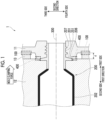
- Fig. 1 is a cross-sectional view showing an example of a configuration of a blow molding mechanism 1 according to the present embodiment.
- Fig. 1 shows a state where the blow molding mechanism 1 is viewed from a top side toward a bottom side in a top-bottom direction. For this reason, a front side of the drawing of Fig. 1 is the top side in the top-bottom direction, and a rear side of the drawing is the bottom side in the top-bottom direction.
- the blow molding mechanism 1 shown in Fig. 1 is a mechanism applied to an intermediate mold and a movable mold that are included in a mold unit which performs injection blow molding.
- the intermediate mold to which the blow molding mechanism 1 is applied is a so-called rotating mold that is disposed between a stationary mold and a movable mold (not shown).
- the stationary mold is disposed on a first side in a first direction with respect to the intermediate mold.
- the movable mold is disposed on a second side in the first direction with respect to the intermediate mold.
- the injection blow molding refers to a molding technique in which injection molding and blow molding are performed in two stages. The injection molding is performed in a state where the stationary mold and the intermediate mold are closed. In addition, the blow molding is performed in a state where the movable mold and the intermediate mold are closed.
- a preform (not shown) which is an intermediate molding product is molded in the injection molding which is first stage molding.
- blow molding which is a second stage molding, high-pressure air is blown into the preform and the preform is extended, thereby molding a final molding product.
- a technique of blowing air into the preform through the blow molding include a technique of causing an extension rod (not shown) that can output the high-pressure air to protrude into the preform.
- Fig. 1 shows a cylindrical bottle container 200 that is a final molding product subjected to blow molding in a mold in a closed state.
- a direction of an axis 300 of the bottle container 200 in a closed state is a right-left direction of the drawing and is the same direction as a direction in which the intermediate mold and the movable mold to which the blow molding mechanism 1 is applied are opened and closed.
- the direction in which the intermediate mold and the movable mold to which the blow molding mechanism 1 is applied are opened and closed (the right-left direction of the drawing of Fig. 1 ) will be called the "first direction”.
- a right side of the drawing in the first direction will be called the "first side”
- a left side of the drawing in the first direction will be called the "second side”.
- a direction perpendicular to the first direction (an up-down direction of the drawing in Fig. 1 ) will be called a "second direction”.
- an upper side of the drawing in the second direction will be called a "third side”
- a lower side of the drawing in the second direction will be called a "fourth side”.
- a filled portion of a cross section of the bottle container 200 indicates a portion where the preform is extended through the blow molding.
- a portion that is extended through the blow molding and a portion that is not extended are not clearly distinguished from each other.
- a boundary portion between the filled portion and a hatched portion in the cross section of the bottle container 200 of Fig. 1 merely indicates an approximate position.
- the bottle container 200 includes a mouth portion 201 and a main body 202.
- the mouth portion 201 and the main body 202 are names of parts of the shape of the bottle container 200 having continuity, and there is no clear boundary. For this reason, in the present embodiment, the mouth portion 201 is a portion that is gripped by the first split mold 11 to be described later and that is subjected to injection molding.
- the mouth portion 201 is a portion including near an end portion of the bottle container 200 on the first side in the first direction, that is, a surface 251 of a protrusion portion 206, which protrudes in a direction separated from the axis 300, of the bottle container 200 on the first side in the first direction and a male screw 207 which is screwed into a female screw of a cap (not shown) of the bottle container 200.
- the main body 202 is a portion molded by the second split mold 12 to be described later. Specifically, the main body 202 is a portion other than the mouth portion 201 of the bottle container 200.
- the blow molding mechanism 1 includes the first split mold 11 and the second split mold 12, which are molds.
- the first split mold 11 is a split mold that can be opened and closed in the second direction and functions as a mold that configures the intermediate mold for performing injection molding and blow molding.
- the first split mold 11 molds the mouth portion 201 in a closed state during the injection molding and grips the mouth portion 201 in the closed state during the blow molding.
- the first split mold 11 is opened to release the mouth portion 201 after the blow molding is completed.
- the first split mold 11 is also called a mouth portion split mold or a split.
- the second split mold 12 is a split mold that can be opened and closed in the second direction and functions as a mold that configures a movable mold which performs blow molding.
- the second split mold 12 molds the main body 202 in a closed state during the blow molding.
- the second split mold 12 is opened to release the main body 202 after the blow molding is completed.
- the second split mold 12 is also called a blow split mold.
- a boundary portion 400 between the first split mold 11 and the second split mold 12 is shown as if the first split mold 11 and the second split mold 12 are in contact with each other.
- a slight gap that does not affect quality of a molding product is formed. For this reason, the first split mold 11 and the second split mold 12 are not in contact with each other.
- the blow molding mechanism 1 includes the sliding member 13 between the first split mold 11 and the second split mold 12.
- the sliding member 13 is attachably and detachably fixed to the second split mold 12 and is slidable with respect to the first split mold 11.
- the sliding member 13 is configured by a member that has a thickness determined in advance in the first direction and that is made of a metal having high abrasion resistance.
- a material for the sliding member 13 is not particularly limited, and is configured by, for example, a so-called non-oil supply plate and the like, in which a solid lubricant is blended in a material and which does not require supply of the lubricant.
- the sliding member 13 is attachably and detachably fixed to the second split mold 12 by a bolt 14.
- a technique of fixing the sliding member 13 to the second split mold 12 is not limited to a technique of fixing with the bolt 14.
- a thickness d of the sliding member 13 in the first direction is designed as follows. That is, the thickness d is designed such that the first split mold 11 and the second split mold 12 are not in contact with each other in a state where the sliding member 13 is fixed to the second split mold 12 and the first split mold 11 is slidable with respect to the sliding member 13.
- a state where the second split mold 12 is closed is shown.
- the sliding member 13 is fixed to the second split mold 12 by the bolt 14.
- a preform is disposed in a circular hole 15 formed in a state where the second split mold 12 is closed.
- the preform is extended, and the bottle container 200 (see Fig. 1 ) is molded.
- the sliding member 13 forms a circular hole having a diameter larger than a diameter of the hole 15 of the second split mold 12 in a state of being closed in the second direction.
- a state where the second split mold 12 is opened in the second direction is shown.
- the first split mold 11 (see Fig. 1 ) that has gripped the mouth portion 201 of the bottle container 200 starts to open in the second direction. Accordingly, the mouth portion 201 of the bottle container 200 is released.
- the second split mold 12 that has gripped the main body 202 of the bottle container 200 starts to open in the second direction. Accordingly, the main body 202 of the bottle container 200 is released.
- the bottle container 200 starts free falling toward the bottom side in the top-bottom direction. In this manner, the mold for performing the blow molding and the bottle container 200, which is the final molding product, are separated from each other.
- the first split mold 11 starts to open and immediately thereafter, the second split mold 12 starts to open. Accordingly, the bottle container 200 is separated from the mold for performing the blow molding. Sliding occurs at the boundary portion 100 between the first split mold 11 and the sliding member 13 when the first split mold 11 starts to open. On the contrary, a distance is provided at the boundary portion 400 between the first split mold 11 and the second split mold 12 to such an extent that sliding does not occur.
- the blow molding mechanism of the related art shown in Fig. 3 includes each of a mouth portion split mold and a blow split mold corresponding to the first split mold 11 and the second split mold 12 of the blow molding mechanism 1, respectively, which are shown in Fig. 1 described above.
- the blow molding mechanism of the related art shown in Fig. 3 does not include the sliding member 13 (see Fig. 1 ) unlike the blow molding mechanism 1 of Fig. 1 .
- sliding occurs at the boundary portion 400 between the mouth portion split mold and the blow split mold, unlike in the blow molding mechanism 1 of in Fig. 1 .
- the boundary portion 400 between the mouth portion split mold and the blow split mold in the blow molding mechanism of the related art shown in Fig. 3 is affected by a mold clamping force in the first direction generated when a mold unit is clamped, and thus, a contact pressure is increased. For this reason, there is a high risk of occurrence of scratching or gnawing caused by sliding.
- scratching or gnawing is likely to occur in the blow split mold.
- a technique for suppressing the occurrence of scratching or gnawing in the blow split mold a technique of changing a material for the blow split mold to a material having high hardness is conceivable. However, when a material for the blow split mold having high hardness is used, machinability of the mold of the blow split mold is degraded.
- the blow molding mechanism 1 of Fig. 1 described above has a configuration where sliding is possible at the boundary portion 100 between the sliding member 13 fixed to the second split mold 12 and the first split mold 11 and contact does not occur at the boundary portion 400 between the first split mold 11 and the second split mold 12. For this reason, a mold clamping force is generated when the mold unit is clamped also in the blow molding mechanism 1 of Fig. 1 as in the blow molding mechanism of the related art shown in Fig. 3 , but the problem described above is unlikely to occur.
- the boundary portion 100 is positioned relatively far from the bottle container 200, which is a product, and accordingly, a risk of attachment of abrasion powder generated due to contact to the bottle container 200 is low.
- the first split mold 11 and the sliding member 13 are formed of a material having abrasion resistance and high hardness. In this manner, a risk of the occurrence of scratching or gnawing at the boundary portion 100 can be reduced.
- a relationship between the hardness of the first split mold 11, the hardness of the second split mold 12, and the hardness of the sliding member 13 in the blow molding mechanism 1 is not particularly limited.
- the following relationship can be given as an example. That is, a material having hardness higher than hardness of the second split mold 12 may be adopted for the first split mold 11 and the sliding member 13. Accordingly, since the material having hardness higher than hardness of the second split mold 12 can be adopted for the first split mold 11 and the sliding member 13, the occurrence of abrasion, scratching, and gnawing can be suppressed.
- the second split mold 12 is a member that does not slide against any one of the first split mold 11 and the sliding member 13, scratching or gnawing caused by sliding does not occur in the first place. As a result, since a material that has low hardness and that is easy to be processed can be adopted, machinability can be improved.
- a material having hardness higher than hardness of the first split mold 11 may be adopted for the sliding member 13. Accordingly, even when contact with the boundary portion 100 between the first split mold 11 and the sliding member 13 occurs, the sliding member 13 is unlikely to be abraded.
- the sliding member 13 has a constraint on a shape, such as the thickness d in the first direction, a length in the second direction, and a length in the top-bottom direction, and a constraint on a material, compared to the first split mold 11. For this reason, the sliding member 13 tends to have a higher frequency of maintenance such as replacement than the first split mold 11 has, and the frequency of maintenance such as replacement can be reduced by increasing the hardness of the sliding member 13 than hardness of the first split mold 11.
- a material having hardness higher than hardness of the sliding member 13 may be adopted for the first split mold 11.
- a material for the first split mold 11 can be a material having hardness higher than hardness of the second split mold 12, even when contact with the boundary portion 100 between the first split mold 11 and the sliding member 13 occurs, the first split mold 11 is unlikely to be abraded. That is, while it is assumed that the replacement of the sliding member 13 is relatively easy and maintenance costs do not increase, maintainability of the first split mold 11, of which replacement is not easy and maintenance costs are high, can be prioritized. Therefore, there is an advantage in terms of costs and operation.
- an operation mechanism to which the present invention is applied can be configured as follows, and various embodiments can be adopted.
- the blow molding mechanism 1 which is the operation mechanism according to the present embodiment, is a blow molding mechanism including the first split mold 11 that is a first member which is a member operating in the second direction perpendicular to the first direction in which the stationary mold and the movable mold are closed and opened, the second split mold 12 that is a member which operates in the second direction and that is a second member which does not come into contact with the first split mold 11, and the sliding member 13 that is attachably and detachably fixed to the second split mold 12 and that is slidable with respect to the first split mold 11.
- the blow molding mechanism 1 which is the operation mechanism, includes the first split mold 11 that is the first member which operates in the second direction perpendicular to the first direction in which the stationary mold and the movable mold are closed and opened and the second split mold 12 that is the second member which operates in the second direction and which does not come into contact with the first split mold 11, and the sliding member 13 that is slidable with respect to the first split mold 11 is attachably and detachably fixed to the second split mold 12.
- first split mold 11 and the sliding member 13 may have hardness higher than hardness of the second split mold 12.
- the sliding member 13 may have hardness higher than hardness of the first split mold 11.
- the blow molding mechanism 1 includes the first split mold 11 that is opened in the second direction perpendicular to the first direction in which the stationary mold and the movable mold are closed and opened and the second split mold 12 that is opened in the second direction and that does not come into contact with the first split mold 11, and the sliding member 13 that is slidable with respect to the first split mold 11 is attachably and detachably fixed to the second split mold 12.
- the split mold to which the present invention is applied is a split mold including the blow molding mechanism 1, which is the operation mechanism, in which the blow molding mechanism 1 includes the first split mold 11 that is the first member which is the member operating in the second direction perpendicular to the first direction in which the stationary mold and the movable mold are opened and closed, the second split mold 12 that is a member which operates in the second direction and that is the second member which does not come into contact with the first split mold 11, and the sliding member 13 that is attachably and detachably fixed to the second split mold 12 and that is slidable with respect to the first split mold 11, and the direction in which the first split mold 11 and the second split mold 12 are opened and closed is perpendicular to the direction in which the stationary mold and the movable mold are opened and closed.
- the blow molding mechanism 1 includes the first split mold 11 that is the first member which is the member operating in the second direction perpendicular to the first direction in which the stationary mold and the movable mold are opened and closed, the second split mold 12 that is a member which
- the mold unit to which the present invention is applied is a mold unit including the stationary mold, the intermediate mold including the blow molding mechanism 1 that is an operation mechanism, and the movable mold, in which the blow molding mechanism 1 includes the first split mold 11 that is the first member which is the member operating in the second direction perpendicular to the first direction in which the stationary mold and the movable mold are closed and opened, the second split mold 12 that is a member which operates in the second direction and that is the second member which does not come into contact with the first split mold 11, and the sliding member 13 that is attachably and detachably fixed to the second split mold 12 and that is slidable with respect to the first split mold 11, and the direction in which the first split mold 11 and the second split mold 12 are closed and opened is perpendicular to the direction in which the stationary mold and the movable mold are closed and opened.
- the blow molding mechanism 1 includes the first split mold 11 that is the first member which is the member operating in the second direction perpendicular to the first direction in which the stationary mold and the movable mold are
- the blow molding mechanism 1 of the intermediate mold and the movable mold included in the mold unit includes the first split mold 11 that is the first member which operates in the second direction perpendicular to the first direction in which the stationary mold and the movable mold are closed and opened and the second split mold 12 that is the second member which operates in the second direction and which does not come into contact with the first split mold 11, and the sliding member 13 that is slidable with respect to the first split mold 11 and that is attachably and detachably fixed to the second split mold 12.
- the present invention is not limited to the embodiment described above.
- the effects of the present invention are also not limited to those described in the embodiment described above.
- the configurations of the blow molding mechanism 1 shown in Fig. 1 are merely examples for achieving the object of the present invention and are not particularly limited.
- a state where the second split mold 12 to which the sliding member 13 is fixed operates, which is shown in Fig. 2 is also merely an example and is not particularly limited.
- the blow molding mechanism 1 can also be applied to a mold unit that does not include the intermediate mold.
- the present invention can also be applied to a mold unit including a stationary mold and a movable mold, in which a split mold is closed and opened in a state where a certain contact pressure or higher caused by mold clamping is applied to the split mold.
- first member according to the present invention is the first split mold 11
- second member according to the present invention is the second split mold 12
- the first member according to the present invention is the member that configures the mold unit and may be a member that operates in the second direction perpendicular to the first direction in which the stationary mold and the movable mold of the mold unit are closed and opened.
- the second member according to the present invention is also the member that configures the mold unit, is the member that operates in the second direction perpendicular to the first direction in which the stationary mold and the movable mold of the mold unit are closed and opened, and may be the member that does not come into contact with the first member.
Landscapes
- Engineering & Computer Science (AREA)
- Manufacturing & Machinery (AREA)
- Mechanical Engineering (AREA)
- Moulds For Moulding Plastics Or The Like (AREA)
- Blow-Moulding Or Thermoforming Of Plastics Or The Like (AREA)
Applications Claiming Priority (1)
| Application Number | Priority Date | Filing Date | Title |
|---|---|---|---|
| JP2023222952A JP2025104827A (ja) | 2023-12-28 | 2023-12-28 | 動作機構、吹込成形機構、割型、および金型装置 |
Publications (2)
| Publication Number | Publication Date |
|---|---|
| EP4578629A2 true EP4578629A2 (de) | 2025-07-02 |
| EP4578629A3 EP4578629A3 (de) | 2025-10-15 |
Family
ID=93924058
Family Applications (1)
| Application Number | Title | Priority Date | Filing Date |
|---|---|---|---|
| EP24219637.6A Pending EP4578629A3 (de) | 2023-12-28 | 2024-12-13 | Betriebsmechanismus, blasformmechanismus, geteilte form und formeinheit |
Country Status (4)
| Country | Link |
|---|---|
| US (1) | US20250214296A1 (de) |
| EP (1) | EP4578629A3 (de) |
| JP (1) | JP2025104827A (de) |
| CN (1) | CN120228881A (de) |
Citations (1)
| Publication number | Priority date | Publication date | Assignee | Title |
|---|---|---|---|---|
| JP4425750B2 (ja) | 2004-04-30 | 2010-03-03 | 住友重機械工業株式会社 | 成形機の成形品把持装置 |
Family Cites Families (3)
| Publication number | Priority date | Publication date | Assignee | Title |
|---|---|---|---|---|
| KR100362530B1 (ko) * | 2000-07-06 | 2002-11-27 | 광명제약 주식회사 | 플라스틱용기 성형장치 |
| CA2652281A1 (en) * | 2006-05-15 | 2007-12-13 | Gala Industries, Inc. | Solid face die plate |
| EP3700496A4 (de) * | 2017-10-24 | 2021-07-21 | Hugopak Pty Ltd | Flasche zum füttern und verfahren zu ihrer herstellung |
-
2023
- 2023-12-28 JP JP2023222952A patent/JP2025104827A/ja active Pending
-
2024
- 2024-12-12 CN CN202411827318.7A patent/CN120228881A/zh active Pending
- 2024-12-13 EP EP24219637.6A patent/EP4578629A3/de active Pending
- 2024-12-21 US US18/991,511 patent/US20250214296A1/en active Pending
Patent Citations (1)
| Publication number | Priority date | Publication date | Assignee | Title |
|---|---|---|---|---|
| JP4425750B2 (ja) | 2004-04-30 | 2010-03-03 | 住友重機械工業株式会社 | 成形機の成形品把持装置 |
Also Published As
| Publication number | Publication date |
|---|---|
| EP4578629A3 (de) | 2025-10-15 |
| US20250214296A1 (en) | 2025-07-03 |
| CN120228881A (zh) | 2025-07-01 |
| JP2025104827A (ja) | 2025-07-10 |
Similar Documents
| Publication | Publication Date | Title |
|---|---|---|
| EP4578628A1 (de) | Formeinheit | |
| US20090151889A1 (en) | Die for Die Casting, Method of Manufacturing Cast Product, and Cast Product | |
| EP3369551B1 (de) | Form, blasformvorrichtung und blasformverfahren | |
| EP4578629A2 (de) | Betriebsmechanismus, blasformmechanismus, geteilte form und formeinheit | |
| CN115210017A (zh) | 具有浇道系统和改进的浇道分离的三板压铸模具和压铸方法 | |
| CN107249849A (zh) | 包括具有清洁构型的模具堆叠以及关闭高度调整机构的模制系统 | |
| US8251125B2 (en) | Metal mold apparatus | |
| JP2015208872A (ja) | エジェクタ装置および成形金型 | |
| US20060198974A1 (en) | Apparatus and method for removing a molded article from a mold, and a molded article | |
| JP2011042149A (ja) | 樹脂成形金型装置 | |
| CN211679958U (zh) | 分流子和铸造装置 | |
| US11772150B2 (en) | Method for manufacturing cast product using breathable salt core | |
| JP3618700B2 (ja) | 射出成形金型 | |
| KR102273673B1 (ko) | 블로우 몰딩 3단 분리 금형 | |
| EP1232848A1 (de) | Blasformverfahren | |
| EP4574397A1 (de) | Blasformmechanismus, zwischenform und formeinheit | |
| EP4566792A1 (de) | Ausziehstangengleitmechanismus, zwischenform und formeinheit | |
| US20210031421A1 (en) | Injection mold and manufacturing method | |
| JPH11268086A (ja) | 成形金型のスプルー・ライナー取り出し機構と取り出し方法 | |
| CN217531718U (zh) | 长抽芯双导向装置 | |
| JP6314003B2 (ja) | 射出成形用金型、及び成形品 | |
| JP2000225621A (ja) | 型構造 | |
| JP5061894B2 (ja) | 金型装置 | |
| JP2006062110A (ja) | 首曲がり容器の樹脂成形方法および樹脂成形装置 | |
| JP4238789B2 (ja) | 雄ねじ成形用金型装置 |
Legal Events
| Date | Code | Title | Description |
|---|---|---|---|
| PUAI | Public reference made under article 153(3) epc to a published international application that has entered the european phase |
Free format text: ORIGINAL CODE: 0009012 |
|
| STAA | Information on the status of an ep patent application or granted ep patent |
Free format text: STATUS: REQUEST FOR EXAMINATION WAS MADE |
|
| 17P | Request for examination filed |
Effective date: 20241213 |
|
| AK | Designated contracting states |
Kind code of ref document: A2 Designated state(s): AL AT BE BG CH CY CZ DE DK EE ES FI FR GB GR HR HU IE IS IT LI LT LU LV MC ME MK MT NL NO PL PT RO RS SE SI SK SM TR |
|
| PUAL | Search report despatched |
Free format text: ORIGINAL CODE: 0009013 |
|
| STAA | Information on the status of an ep patent application or granted ep patent |
Free format text: STATUS: EXAMINATION IS IN PROGRESS |
|
| AK | Designated contracting states |
Kind code of ref document: A3 Designated state(s): AL AT BE BG CH CY CZ DE DK EE ES FI FR GB GR HR HU IE IS IT LI LT LU LV MC ME MK MT NL NO PL PT RO RS SE SI SK SM TR |
|
| RIC1 | Information provided on ipc code assigned before grant |
Ipc: B29C 49/56 20060101AFI20250911BHEP Ipc: B29C 49/42 20060101ALI20250911BHEP Ipc: B29C 49/54 20060101ALN20250911BHEP Ipc: B29C 49/02 20060101ALN20250911BHEP Ipc: B29C 49/48 20060101ALN20250911BHEP Ipc: B29L 31/00 20060101ALN20250911BHEP |
|
| 17Q | First examination report despatched |
Effective date: 20250930 |