EP4578433A2 - Halterung zur befestigung eines robotersystems an einem patiententisch - Google Patents
Halterung zur befestigung eines robotersystems an einem patiententisch Download PDFInfo
- Publication number
- EP4578433A2 EP4578433A2 EP25176615.0A EP25176615A EP4578433A2 EP 4578433 A2 EP4578433 A2 EP 4578433A2 EP 25176615 A EP25176615 A EP 25176615A EP 4578433 A2 EP4578433 A2 EP 4578433A2
- Authority
- EP
- European Patent Office
- Prior art keywords
- rail
- support
- pad
- patient
- force
- Prior art date
- Legal status (The legal status is an assumption and is not a legal conclusion. Google has not performed a legal analysis and makes no representation as to the accuracy of the status listed.)
- Pending
Links
Images


Classifications
-
- A—HUMAN NECESSITIES
- A61—MEDICAL OR VETERINARY SCIENCE; HYGIENE
- A61G—TRANSPORT, PERSONAL CONVEYANCES, OR ACCOMMODATION SPECIALLY ADAPTED FOR PATIENTS OR DISABLED PERSONS; OPERATING TABLES OR CHAIRS; CHAIRS FOR DENTISTRY; FUNERAL DEVICES
- A61G13/00—Operating tables; Auxiliary appliances therefor
- A61G13/10—Parts, details or accessories
- A61G13/101—Clamping means for connecting accessories to the operating table
-
- A—HUMAN NECESSITIES
- A61—MEDICAL OR VETERINARY SCIENCE; HYGIENE
- A61G—TRANSPORT, PERSONAL CONVEYANCES, OR ACCOMMODATION SPECIALLY ADAPTED FOR PATIENTS OR DISABLED PERSONS; OPERATING TABLES OR CHAIRS; CHAIRS FOR DENTISTRY; FUNERAL DEVICES
- A61G13/00—Operating tables; Auxiliary appliances therefor
- A61G13/02—Adjustable operating tables; Controls therefor
- A61G13/08—Adjustable operating tables; Controls therefor the table being divided into different adjustable sections
-
- A—HUMAN NECESSITIES
- A47—FURNITURE; DOMESTIC ARTICLES OR APPLIANCES; COFFEE MILLS; SPICE MILLS; SUCTION CLEANERS IN GENERAL
- A47C—CHAIRS; SOFAS; BEDS
- A47C21/00—Attachments for beds, e.g. sheet holders or bed-cover holders; Ventilating, cooling or heating means in connection with bedsteads or mattresses
-
- A—HUMAN NECESSITIES
- A61—MEDICAL OR VETERINARY SCIENCE; HYGIENE
- A61G—TRANSPORT, PERSONAL CONVEYANCES, OR ACCOMMODATION SPECIALLY ADAPTED FOR PATIENTS OR DISABLED PERSONS; OPERATING TABLES OR CHAIRS; CHAIRS FOR DENTISTRY; FUNERAL DEVICES
- A61G7/00—Beds specially adapted for nursing; Devices for lifting patients or disabled persons
- A61G7/002—Beds specially adapted for nursing; Devices for lifting patients or disabled persons having adjustable mattress frame
- A61G7/015—Beds specially adapted for nursing; Devices for lifting patients or disabled persons having adjustable mattress frame divided into different adjustable sections, e.g. for Gatch position
-
- A—HUMAN NECESSITIES
- A61—MEDICAL OR VETERINARY SCIENCE; HYGIENE
- A61G—TRANSPORT, PERSONAL CONVEYANCES, OR ACCOMMODATION SPECIALLY ADAPTED FOR PATIENTS OR DISABLED PERSONS; OPERATING TABLES OR CHAIRS; CHAIRS FOR DENTISTRY; FUNERAL DEVICES
- A61G7/00—Beds specially adapted for nursing; Devices for lifting patients or disabled persons
- A61G7/05—Parts, details or accessories of beds
-
- A—HUMAN NECESSITIES
- A61—MEDICAL OR VETERINARY SCIENCE; HYGIENE
- A61G—TRANSPORT, PERSONAL CONVEYANCES, OR ACCOMMODATION SPECIALLY ADAPTED FOR PATIENTS OR DISABLED PERSONS; OPERATING TABLES OR CHAIRS; CHAIRS FOR DENTISTRY; FUNERAL DEVICES
- A61G2210/00—Devices for specific treatment or diagnosis
- A61G2210/50—Devices for specific treatment or diagnosis for radiography
Definitions
- the present invention relates generally to the field of robotic medical procedure systems and, in particular, to a support for securing a robotic system to a patient table.
- Catheters and other elongated medical devices may be used for minimally-invasive medical procedures for the diagnosis and treatment of diseases of various vascular systems, including neurovascular intervention (NVI) also known as neurointerventional surgery, percutaneous coronary intervention (PCI) and peripheral vascular intervention (PVI).
- NVI neurovascular intervention
- PCI percutaneous coronary intervention
- PVI peripheral vascular intervention
- These procedures typically involve navigating a guidewire through the vasculature, and via the guidewire advancing a catheter to deliver therapy.
- the catheterization procedure starts by gaining access into the appropriate vessel, such as an artery or vein, with an introducer sheath using standard percutaneous techniques.
- a sheath or guide catheter is then advanced over a diagnostic guidewire to a primary location such as an internal carotid artery for NVI, a coronary ostium for PCI, or a superficial femoral artery for PVI.
- a guidewire suitable for the vasculature is then navigated through the sheath or guide catheter to a target location in the vasculature.
- a support catheter or microcatheter is inserted over the guidewire to assist in navigating the guidewire.
- the physician or operator may use an imaging system (e.g., fluoroscope) to obtain a cine with a contrast injection and select a fixed frame for use as a roadmap to navigate the guidewire or catheter to the target location, for example, a lesion. Contrast-enhanced images are also obtained while the physician delivers the guidewire or catheter so that the physician can verify that the device is moving along the correct path to the target location. While observing the anatomy using fluoroscopy, the physician manipulates the proximal end of the guidewire or catheter to direct the distal tip into the appropriate vessels toward the lesion or target anatomical location and avoid advancing into side branches.
- an imaging system e.g., fluoroscope
- Robotic catheter-based procedure systems have been developed that may be used to aid a physician in performing catheterization procedures such as, for example, NVI, PCI and PVI.
- NVI procedures include coil embolization of aneurysms, liquid embolization of arteriovenous malformations and mechanical thrombectomy of large vessel occlusions in the setting of acute ischemic stroke.
- the physician uses a robotic system to gain target lesion access by controlling the manipulation of a neurovascular guidewire and microcatheter to deliver the therapy to restore normal blood flow.
- Target access is enabled by the sheath or guide catheter but may also require an intermediate catheter for more distal territory or to provide adequate support for the microcatheter and guidewire.
- the distal tip of a guidewire is navigated into, or past, the lesion depending on the type of lesion and treatment.
- the microcatheter is advanced into the lesion and the guidewire is removed and several embolization coils are deployed into the aneurysm through the microcatheter and used to block blood flow into the aneurysm.
- a liquid embolic is injected into the malformation via a microcatheter. Mechanical thrombectomy to treat vessel occlusions can be achieved either through aspiration and/or use of a stent retriever.
- aspiration is either done through an aspiration catheter, or through a microcatheter for smaller arteries. Once the aspiration catheter is at the lesion, negative pressure is applied to remove the clot through the catheter. Alternatively, the clot can be removed by deploying a stent retriever through the microcatheter. Once the clot has integrated into the stent retriever, the clot is retrieved by retracting the stent retriever and microcatheter (or intermediate catheter) into the guide catheter.
- the physician uses a robotic system to gain lesion access by manipulating a coronary guidewire to deliver the therapy and restore normal blood flow.
- the access is enabled by seating a guide catheter in a coronary ostium.
- the distal tip of the guidewire is navigated past the lesion and, for complex anatomies, a microcatheter may be used to provide adequate support for the guidewire.
- the blood flow is restored by delivering and deploying a stent or balloon at the lesion.
- the lesion may need preparation prior to stenting, by either delivering a balloon for pre-dilation of the lesion, or by performing atherectomy using, for example, a laser or rotational atherectomy catheter and a balloon over the guidewire. Diagnostic imaging and physiological measurements may be performed to determine appropriate therapy by using imaging catheters or fractional flow reserve (FFR) measurements.
- FFR fractional flow reserve
- the physician uses a robotic system to deliver the therapy and restore blood flow with techniques similar to NVI.
- the distal tip of the guidewire is navigated past the lesion and a microcatheter may be used to provide adequate support for the guidewire for complex anatomies.
- the blood flow is restored by delivering and deploying a stent or balloon to the lesion.
- lesion preparation and diagnostic imaging may be used as well.
- an over-the-wire (OTW) catheter or coaxial system When support at the distal end of a catheter or guidewire is needed, for example, to navigate tortuous or calcified vasculature, to reach distal anatomical locations, or to cross hard lesions, an over-the-wire (OTW) catheter or coaxial system is used.
- An OTW catheter has a lumen for the guidewire that extends the full length of the catheter. This provides a relatively stable system because the guidewire is supported along the whole length. This system, however, has some disadvantages, including higher friction, and longer overall length compared to rapid-exchange catheters (see below).
- the exposed length (outside of the patient) of guidewire must be longer than the OTW catheter.
- a 300 cm long guidewire is typically sufficient for this purpose and is often referred to as an exchange length guidewire. Due to the length of the guidewire, two operators are needed to remove or exchange an OTW catheter. This becomes even more challenging if a triple coaxial, known in the art as a triaxial system, is used (quadruple coaxial catheters have also been known to be used). However, due to its stability, an OTW system is often used in NVI and PVI procedures. On the other hand, PCI procedures often use rapid exchange (or monorail) catheters. The guidewire lumen in a rapid exchange catheter runs only through a distal section of the catheter, called the monorail or rapid exchange (RX) section.
- RX rapid exchange
- RX With a RX system, the operator manipulates the interventional devices parallel to each other (as opposed to with an OTW system, in which the devices are manipulated in a serial configuration), and the exposed length of guidewire only needs to be slightly longer than the RX section of the catheter.
- a rapid exchange length guidewire is typically 180-200 cm long. Given the shorter length guidewire and monorail, RX catheters can be exchanged by a single operator. However, RX catheters are often inadequate when more distal support is needed.
- a support attaches a mechanism to a patient table having a patient supporting surface and a first rail and a second rail.
- the support comprising: a base comprising; a first engagement member; a second engagement member; and a single engagement mechanism moving the first engagement member and the second engagement member from a loading position to a secured position securing the base to the first rail and the second rail.
- first engagement member is configured to contact a bottom of the first rail and the second engagement member is configured to contact a bottom of the second rail in the secured position.
- the base includes a first pad contacting the patient supporting surface.
- the first pad is biased by a biasing member applying a pad force to the patient supporting table.
- the pad force is substantially constant.
- the single engagement mechanism secures the base in a cross-table direction, parallel to a patient table plane defining the patient supporting surface, and in a vertical direction perpendicular to the patient supporting surface.
- the single engagement mechanism includes a cam mechanism having a first cam surface moving the base in the cross-table direction.
- the cam mechanism includes a second cam surface moving the base in the vertical direction.
- a medical device system is attached to the support, the medical device system having a center of mass providing a system force onto the first rail and second rail, wherein the pad force and the system force does not exceed a predetermined limit force on the first rail, the second rail and the patient supporting surface.
- the center of mass of the medical device system moves within a predefined region during active operation of the medical device system and wherein the predetermined force is not exceeded.
- the first pad contacts the patient supporting surface closer to the first rail than the second rail.
- the first pad contacts the patient supporting surface intermediate the first rail and the second rail.
- the patient table includes a table marker
- the base includes a base marker, wherein the base marker is aligned with the table marker in the secured position.
- the single engagement mechanism is actuated by movement of a member in a single direction.
- a support attaches a mechanism to a patient table having a patient supporting surface and a first rail and a second rail.
- the support comprising: a base including a pad positioned intermediate the first rail and the second rail, the pad biased by a biasing member in a first direction, the first pad configured to contact the patient supporting surface of the patient table.
- a first engagement member is configured to contact the first rail; and a second engagement member is configured to contact the second rail. The pad applies a pad force to the patient supporting surface when the pad is contact with the patient supporting surface.
- a stop member is connected to the base, the stop member limiting a distance the pad can extend in the first direction and maintaining the biasing member in a preloaded state when the pad is not in contact with the patient supporting surface.
- a full force of the biasing member is applied to the patient supporting surface when the pad contacts the patient supporting surface and the pad moves in a second direction away from the stop member.
- a medical device system configured to be attached to the support, the medical device system having a center of mass providing a system force onto the first rail and the second rail, wherein the pad force and the system force does not exceed a predetermined limit force on the first rail, the second rail and the patient supporting surface, wherein the force of the support and the medical device system is distributed between the first rail, the second rail, and the patient supporting surface.
- a medical device system configured to be attached to the support, the medical device system having a center of mass providing a system force onto the first rail and the second rail, wherein the pad force and the system force does not exceed a predetermined limit force on the first rail, the second rail and the patient supporting surface.
- a contrast media is injected onto one or more arteries through a catheter and an image of the patient's vasculature is taken.
- Catheter-based medical procedures may also include catheter-based therapeutic procedures (e.g., angioplasty, stent placement, treatment of peripheral vascular disease, clot removal, arterial venous malformation therapy, treatment of aneurysm, etc.) during which a catheter (or other EMD) is used to treat a disease.
- Therapeutic procedures may be enhanced by the inclusion of adjunct devices 54 (shown in FIG. 2 ) such as, for example, intravascular ultrasound (IVUS), optical coherence tomography (OCT), fractional flow reserve (FFR), etc.
- IVUS intravascular ultrasound
- OCT optical coherence tomography
- FFR fractional flow reserve
- Catheter-based procedure system 10 can perform any number of catheter-based medical procedures with minor adjustments to accommodate the specific percutaneous intervention devices to be used in the procedure.
- Catheter-based procedure system 10 includes, among other elements, a bedside unit 20 and a control station (not shown).
- Bedside unit 20 includes a robotic drive 24 and a positioning system 22 that are located adjacent to a patient 12.
- Patient 12 is supported on a patient table 18.
- the positioning system 22 is used to position and support the robotic drive 24.
- the positioning system 22 may be, for example, a robotic arm, an articulated arm, a holder, etc.
- the positioning system 22 may be attached at one end to, for example, the patient table 18 (as shown in FIG. 1 ), a base, or a cart. The other end of the positioning system 22 is attached to the robotic drive 24.
- the positioning system 22 may be moved out of the way (along with the robotic drive 24) to allow for the patient 12 to be placed on the patient table 18. Once the patient 12 is positioned on the patient table 18, the positioning system 22 may be used to situate or position the robotic drive 24 relative to the patient 12 for the procedure.
- patient table 18 is operably supported by a pedestal 17, which is secured to the floor and/or earth. Patient table 18 is able to move with multiple degrees of freedom, for example, roll, pitch, and yaw, relative to the pedestal 17.
- Bedside unit 20 may also include controls and displays 46 (shown in FIG. 2 ). For example, controls and displays may be located on a housing of the robotic drive 24.
- the robotic drive 24 may be equipped with the appropriate percutaneous interventional devices and accessories 48 (shown in FIG. 2 ) (e.g., guidewires, various types of catheters including balloon catheters, stent delivery systems, stent retrievers, embolization coils, liquid embolics, aspiration pumps, device to deliver contrast media, medicine, hemostasis valve adapters, syringes, stopcocks, inflation device, etc.) to allow a user or operator to perform a catheter-based medical procedure via a robotic system by operating various controls such as the controls and inputs located at the control station.
- Bedside unit 20, and in particular robotic drive 24, may include any number and/or combination of components to provide bedside unit 20 with the functionality described herein.
- the robotic drive 24 includes a plurality of device modules 32a-d mounted to a rail or linear member. Each of the device modules 32a-d may be used to drive an EMD such as a catheter or guidewire. For example, the robotic drive 24 may be used to automatically feed a guidewire into a diagnostic catheter and into a guide catheter in an artery of the patient 12.
- One or more devices, such as an EMD enter the body (e.g., a vessel) of the patient 12 at an insertion point 16 via, for example, an introducer sheath.
- a local site is the location of the bedside unit 20 and a patient 12 or subject (e.g., animal or cadaver) and the remote site is the location of a user or operator and a control station used to control the bedside unit 20 remotely.
- a control station (and a control computing system) at a remote site and the bedside unit 20 and/or a control computing system at a local site may be in communication using communication systems and services 36 (shown in FIG. 2 ), for example, through the Internet.
- the remote site and the local (patient) site are away from one another, for example, in different rooms in the same building, different buildings in the same city, different cities, or other different locations where the remote site does not have physical access to the bedside unit 20 and/or patient 12 at the local site.
- the control station generally includes one or more input modules 28 configured to receive user inputs to operate various components or systems of catheter-based procedure system 10.
- control station allows the user or operator to control bedside unit 20 to perform a catheter-based medical procedure.
- input modules 28 may be configured to cause bedside unit 20 to perform various tasks using percutaneous intervention devices (e.g., EMDs) interfaced with the robotic drive 24 (e.g., to advance, retract, or rotate a guidewire, advance, retract or rotate a catheter, inflate or deflate a balloon located on a catheter, position and/or deploy a stent, position and/or deploy a stent retriever, position and/or deploy a coil, inject contrast media into a catheter, inject liquid embolics into a catheter, inject medicine or saline into a catheter, aspirate on a catheter, or to perform any other function that may be performed as part of a catheter-based medical procedure).
- Robotic drive 24 includes various drive mechanisms to cause movement (e.g., axial and
- Input modules 28 may also include a balloon or stent control that is configured to inflate or deflate a balloon and/or deploy a stent.
- Each of the input modules 28 may include one or more buttons, scroll wheels, joysticks, touch screen, etc. that may be used to control the particular component or components to which the control is dedicated.
- one or more touch screens may display one or more icons (not shown) related to various portions of input modules 28 or to various components of catheter-based procedure system 10.
- Imaging system 14 may be any medical imaging system that may be used in conjunction with a catheter based medical procedure (e.g., non-digital X-ray, digital X-ray, CT, MRI, ultrasound, etc.).
- imaging system 14 is a digital X-ray imaging device that is in communication with the control station.
- imaging system 14 may include a C-arm (shown in FIG. 1 ) that allows imaging system 14 to partially or completely rotate around patient 12 in order to obtain images at different angular positions relative to patient 12 (e.g., sagittal views, caudal views, anterior-posterior views, etc.).
- imaging system 14 is a fluoroscopy system including a C-arm having an X-ray source 13 and a detector 15, also known as an image intensifier.
- Imaging system 14 may be configured to take X-ray images of the appropriate area of patient 12 during a procedure.
- imaging system 14 may be configured to take one or more X-ray images of the head to diagnose a neurovascular condition.
- Imaging system 14 may also be configured to take one or more X-ray images (e.g., real time images) during a catheter-based medical procedure to assist the user or operator 11 of control station 26 to properly position a guidewire, guide catheter, microcatheter, stent retriever, coil, stent, balloon, etc. during the procedure.
- the image or images may be displayed on display 30.
- images may be displayed on a display to allow the user or operator to accurately move a guide catheter or guidewire into the proper position.
- a rectangular coordinate system is introduced with X, Y, and Z axes.
- the positive X axis is oriented in a longitudinal (axial) distal direction, that is, in the direction from the proximal end to the distal end, stated another way from the proximal to distal direction.
- the Y and Z axes are in a transverse plane to the X axis, with the positive Z axis oriented up, that is, in the direction opposite of gravity, and the Y axis is automatically determined by right-hand rule.
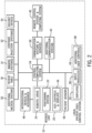
- FIG. 2 is a block diagram of catheter-based procedure system 10 in accordance with an example embodiment.
- Catheter-procedure system 10 may include a control computing system 34.
- Control computing system 34 may physically be, for example, part of a control station.
- Control computing system 34 may generally be an electronic control unit suitable to provide catheter-based procedure system 10 with the various functionalities described herein.
- control computing system 34 may be an embedded system, a dedicated circuit, a general-purpose system programmed with the functionality described herein, etc.
- Control computing system 34 is in communication with bedside unit 20, communications systems and services 36 (e.g., Internet, firewalls, cloud services, session managers, a hospital network, etc.), a local control station 38, additional communications systems 40 (e.g., a telepresence system), a remote control station and computing system 42, and patient sensors 56 (e.g., electrocardiogram (ECG) devices, electroencephalogram (EEG) devices, blood pressure monitors, temperature monitors, heart rate monitors, respiratory monitors, etc.).
- ECG electrocardiogram
- EEG electroencephalogram
- the control computing system is also in communication with imaging system 14, patient table 18, additional medical systems 50, contrast injection systems 52 and adjunct devices 54 (e.g., IVUS, OCT, FFR, etc.).
- the bedside unit 20 includes a robotic drive 24, a positioning system 22 and may include additional controls and displays 46. As mentioned above, the additional controls and displays may be located on a housing of the robotic drive 24. Interventional devices and accessories 48 (e.g., guidewires, catheters, etc.) interface to the bedside system 20. In an embodiment, interventional devices and accessories 48 may include specialized devices (e.g., IVUS catheter, OCT catheter, FFR wire, diagnostic catheter for contrast, etc.) which interface to their respective adjunct devices 54, namely, an IVUS system, an OCT system, and FFR system, etc.
- Interventional devices and accessories 48 may include specialized devices (e.g., IVUS catheter, OCT catheter, FFR wire, diagnostic catheter for contrast, etc.) which interface to their respective adjunct devices 54, namely, an IVUS system, an OCT system, and FFR system, etc.
- control computing system 34 is configured to generate control signals based on the user's interaction with input modules 28 (e.g., of a control station such as a local control station 38 or a remote control station 42) and/or based on information accessible to control computing system 34 such that a medical procedure may be performed using catheter-based procedure system 10.
- the local control station 38 includes one or more displays 30, one or more input modules 28, and additional user controls 44.
- the remote control station and computing system 42 may include similar components to the local control station 38.
- the remote 42 and local 38 control stations can be different and tailored based on their required functionalities.
- the additional user controls 44 may include, for example, one or more foot input controls.
- the foot input control may be configured to allow the user to select functions of the imaging system 14 such as turning on and off the X-ray and scrolling through different stored images.
- a foot input device may be configured to allow the user to select which devices are mapped to scroll wheels included in input modules 28.
- Additional communication systems 40 e.g., audio conference, video conference, telepresence, etc.
- medical staff e.g., angio-suite staff
- equipment in the vicinity of the bedside.
- Catheter-based procedure system 10 may be connected or configured to include any other systems and/or devices not explicitly shown.
- catheter-based procedure system 10 may include image processing engines, data storage and archive systems, automatic balloon and/or stent inflation systems, medicine injection systems, medicine tracking and/or logging systems, user logs, encryption systems, systems to restrict access or use of catheter-based procedure system 10, etc.
- control computing system 34 is in communication with bedside unit 20 which includes a robotic drive 24, a positioning system 22 and may include additional controls and displays 46, and may provide control signals to the bedside unit 20 to control the operation of the motors and drive mechanisms used to drive the percutaneous intervention devices (e.g., guidewire, catheter, etc.).
- the various drive mechanisms may be provided as part of a robotic drive 24.
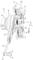
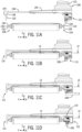
- FIG. 3 a side view of the example catheter-based procedure system 10 of FIG. 1 is illustrated with certain components (e.g., patient, C-arm) removed for clarity.
- the patient table 18 is supported on the pedestal 17, and the robotic drive 24 is mounted to the patient table with a positioning system 22.
- the positioning system 22 allows manipulation of the robotic drive 24 relative to the patient table 18.
- the positioning system 22 is securely mounted to the patient table 18 and includes various joints and links/arms to allow the manipulation, as described below with reference to FIG. 4 .
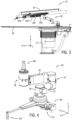
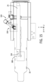
- FIG. 4 is a perspective view of an example positioning system 22 for a robotic drive in accordance with an embodiment.
- the positioning system 22 includes a mounting arrangement 60 to securely mount the positioning system 22 to the patient table 18.
- the mounting arrangement 60 includes an engagement mechanism to engage a first engagement member with a first longitudinal rail and a second engagement member with a second longitudinal rail to removably secure the positioning system to the patient bed.
- the positioning system 22 includes various segments and joints coupling to allow the robotic drive 24 to be positioned as desired, for example, relative to the patient.
- the positioning system 22 includes a first rotational joint 70 coupled to the mounting arrangement 60.
- the first rotational joint 70 allows rotation of a first arm 72, or link, about a rotational axis.
- the mounting arrangement 60 is in a substantially horizontal plane (e.g., the plane of the patient table 18), and the rotational axis is substantially vertical and runs through the center of the first rotational joint 70.
- the first rotational joint 70 can include circuitry to allow a user to control the rotation of the first rotational joint 70.
- the first arm 72 is substantially horizontal with a first end coupled to the first rotational joint 70.
- the second end of the first arm 72 is coupled to a second rotational joint 74.
- the second rotational joint 74 is also coupled to a first end of a second arm 76.
- the second rotational joint 74 allows rotation of the second arm 76 relative to the first arm 72.
- the second rotational joint 74 allows rotation about a substantially vertical axis running through the center of the second rotational joint 74.
- the second rotational joint 74 can include circuitry to allow a user to control the rotation of the second rotational joint 74.
- a second end of the second arm 76 is coupled to a third rotational joint 78.
- the third rotational joint 78 includes a post 80 to allow mounting of the robotic drive 24 to the positioning system 22.
- the third rotational joint 78 allows rotation of the robotic drive 24 relative to the second arm 76.
- the third rotational joint 78 allows rotation about a substantially vertical axis running through the center of the third rotational joint 78.
- the third rotational joint 78 can include circuitry to allow a user to control the rotation of the third rotational joint 78.
- the second arm 76 includes a 4-arm linkage which can allow limited vertical movement of third rotational joint 78 relative to the second rotational joint 74.
- the 4-arm linkage can allow vertical movement of the third rotational join 78, while maintaining the substantially vertical orientation of the third rotational joint 78 and the post 80.
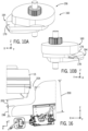
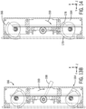
- mounting arrangement 60 in one implementation includes a support 100 for attaching a mechanism such as a robotic drive 24 to a patient table 18 having a patient supporting surface 102 a first rail 104 and an opposing second rail 106.
- Support 100 includes a base 108.
- base 108 includes an articulated arm 110 integrated therewith to support the mechanism such as robotic drive 24.
- Support 100 includes a first engagement member 112 and a second engagement member 114.
- An engagement mechanism 116 operatively moves first engagement member 112 and moves second engagement member 114 from a loading position to a secured position securing base 108 to first rail 104 and opposing second rail 106.
- patient table 18 includes a patient supporting surface 102 having a first longitudinal end 118 and an opposing second longitudinal end 120.
- a patient's head is closer to first longitudinal end 118 than second longitudinal end 120
- the patient's feet are closer to opposing second longitudinal end 120 than first longitudinal end 118.
- First rail 104 extends from an outer periphery of the first longitudinal side 122 away from the second longitudinal side 124.
- Second rail 106 extends from an outer periphery of the second longitudinal side 124 in a direction away from first longitudinal side 122.
- patient supporting surface 102 is horizontal such that the direction of gravity is perpendicular to a plane defined by the patient supporting surface.
- the patient supporting surface is parallel to the X-Y plane.
- the direction perpendicular to the plane defined by the patient supporting surface is referred to herein as the vertical direction and movement along the vertical direction in the direction of gravity is referred to as lowering.
- the vertical direction as used herein refers to direction along the Z axis.
- a surface of patient table 18 that faces away from the direction of gravity in the patient table in-use position is referred to as the upper surface and a surface that faces toward the direction of gravity in the patient table in-use position is referred to as the lower surface.
- first rail 104 includes a first rail upper surface 126 and a first rail lower surface 128, where the first rail upper surface 126 is closer to the patient table supporting surface 102 than the first rail lower surface 128.
- opposing second rail 106 includes a second rail upper surface 130 and an opposing second rail lower surface 132, where the second rail upper surface 130 is closer to the patient table supporting surface 102 than the second rail lower surface 132.
- First rail 104 includes an outer surface 134 extending between first rail upper surface 126 and first rail lower surface 128. Outer surface 134 faces away from second rail 106.
- Second rail 106 includes an outer surface 136.
- Base 108 includes a cross-arm 138 supporting the second engagement member 114.
- Cross-arm 138 slidably extends from a body 140 of base 108.
- Cross-arm 138 can be adjusted relative to body 140 to accommodate patient beds having different cross-bed dimensions.
- First engagement member 112 can be adjusted in the vertical direction (Z-axis) by adjustment 206 connecting first engagement member housing 117 to body 140.
- the cross-table direction is the direction extending perpendicular from outer surface 134 of first rail 104 toward outer surface 136 of second rail 106.
- Second engagement member 114 includes a tab 142 that can be positioned along vertically extending member 144 of cross-arm 138.
- support 100 is placed on patient table 18 at a specific location along the longitudinal axis.
- a marker such as a table marker or other table indicia is placed at a specific location along the longitudinal axis of patient table 18.
- Support 100 has indicia that is aligned with the table indicia so that the robotic mechanism can move within a predefined range of motion.
- the alignment of support 100 on patient table 18 as discussed aids in avoiding interference between robotic drive 24 and imaging system 14. Additionally, alignment of support 100 on patient table 18 assists in positioning robotic drive 24 relative to a patient without running out of reach.
- table marker may be permanently clamped to first rail 104 and table marker may include two portions that are located on either side longitudinally along first rail 104 along the X-axis such that engagement mechanism 116 is located between the two portions of the table marker.
- Both lowering support 100 along a vector parallel to a direction perpendicular to patient supporting surface 102 and lowering support 100 by first contacting ledge 119 of support 100 on first rail upper surface 126 and then lowering cross-arm onto patient supporting surface 102 results in support 100 being in a first loading position.
- a user first lowers the region of support 100 proximate second engagement member 114 onto the region of patient table 18 proximate second rail 106 and then lower the first engagement member 112 toward first rail 104.
- first engagement member 112 and second engagement member 114 are spaced from first rail 104 and second rail 106 respectively. Stated another way the distance between outer surface 134 of first rail 104 and outer surface 136 of second rail 106 is less than the distance between first engagement member 112 and second engagement member 114 in the cross-table direction.
- first engagement member 112 contacts first rail lower surface 128 and outer surface 134 of first rail 104 and second engagement member 114 contacts opposing second rail lower surface 132 and outer surface 136 of second engagement member 114.
- base 108 contacts patient supporting surface 102.
- a first pad 150 extending from a lower surface of body 140 contacts patient supporting surface 102.
- ledge 119 does not contact first rail upper surface 126 of first rail 104.
- support 100 does not contact second rail upper surface 130 and first rail upper surface 126.
- first rail upper surface 126 does contact a portion 121 of support member 119 in response to a pitch moment.
- first rail upper surface 126 and portion 121 of support member 119 there is a clearance between first rail upper surface 126 and portion 121 of support member 119 between 0.0 - 0.2 mm. In operation given however, portion 121 contacts first rail upper surface 126 on at least some longitudinal areas of first rail 104. Note that the gap between first rail upper surface 126 and portion 121 can be adjusted by movement of support member 119 relative to first engagement member housing 117.
- support member 119 is attached to first engagement member housing 117 with a fastener and at least one shim maybe added or removed between support member 119 and first engagement member housing 117 to change the distance between support member 119 and first rail upper surface 126.
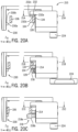
- a second pad 152 extending downwardly from support 100 contacts patient supporting surface 102.
- first pad 150 and second pad 152 and/or both cam assemblies contact patient supporting surface 102 and first rail 104 respectively.
- Patient tables include a first and second longitudinally extending rail on the right side and left side of the patient table.
- a number of different devices are supported on the right and left rails.
- the first rail and the second rail can support a certain amount of mass before the force applied to the first rail and / or second rail lose their ability to positively locate the device relative to the patient supporting surface. While rails are often rated on weight the location of force of the devices secured to the rail may apply an undesirable torque to the rails. Devices that have significant mass may bend and/or torque the first rail 104 and/or second rail 106.
- first pad 150 is biased by a biasing member applying a pad force to patient supporting surface 102.
- the pad force is substantially constant during movement of the arm and robotic drive.
- the pad force acts to counter act the forces applied to patient table 18 from the support and robotic drive 24.
- springs 180 are preloaded so that as soon as the pad is displaced from the hard stops 151 the full force of springs 180 are applied.
Landscapes
- Health & Medical Sciences (AREA)
- Life Sciences & Earth Sciences (AREA)
- Animal Behavior & Ethology (AREA)
- General Health & Medical Sciences (AREA)
- Public Health (AREA)
- Veterinary Medicine (AREA)
- Nursing (AREA)
- Engineering & Computer Science (AREA)
- Biomedical Technology (AREA)
- Accommodation For Nursing Or Treatment Tables (AREA)
- Apparatus For Radiation Diagnosis (AREA)
Applications Claiming Priority (3)
| Application Number | Priority Date | Filing Date | Title |
|---|---|---|---|
| US202163203794P | 2021-07-30 | 2021-07-30 | |
| US17/813,154 US11844732B2 (en) | 2021-07-30 | 2022-07-18 | Support for securing a robotic system to a patient table |
| EP22187243.5A EP4124328B1 (de) | 2021-07-30 | 2022-07-27 | Halterung zur befestigung eines robotersystems an einem patiententisch |
Related Parent Applications (1)
| Application Number | Title | Priority Date | Filing Date |
|---|---|---|---|
| EP22187243.5A Division EP4124328B1 (de) | 2021-07-30 | 2022-07-27 | Halterung zur befestigung eines robotersystems an einem patiententisch |
Publications (2)
| Publication Number | Publication Date |
|---|---|
| EP4578433A2 true EP4578433A2 (de) | 2025-07-02 |
| EP4578433A3 EP4578433A3 (de) | 2025-09-03 |
Family
ID=82748281
Family Applications (2)
| Application Number | Title | Priority Date | Filing Date |
|---|---|---|---|
| EP22187243.5A Active EP4124328B1 (de) | 2021-07-30 | 2022-07-27 | Halterung zur befestigung eines robotersystems an einem patiententisch |
| EP25176615.0A Pending EP4578433A3 (de) | 2021-07-30 | 2022-07-27 | Halterung zur befestigung eines robotersystems an einem patiententisch |
Family Applications Before (1)
| Application Number | Title | Priority Date | Filing Date |
|---|---|---|---|
| EP22187243.5A Active EP4124328B1 (de) | 2021-07-30 | 2022-07-27 | Halterung zur befestigung eines robotersystems an einem patiententisch |
Country Status (4)
| Country | Link |
|---|---|
| US (2) | US11844732B2 (de) |
| EP (2) | EP4124328B1 (de) |
| JP (2) | JP7342211B2 (de) |
| CN (2) | CN115670832A (de) |
Families Citing this family (12)
| Publication number | Priority date | Publication date | Assignee | Title |
|---|---|---|---|---|
| CN116211466A (zh) * | 2014-03-17 | 2023-06-06 | 直观外科手术操作公司 | 用于利用基准标记的台姿态跟踪的方法和装置 |
| US11844732B2 (en) * | 2021-07-30 | 2023-12-19 | Corindus, Inc. | Support for securing a robotic system to a patient table |
| US12419703B2 (en) | 2022-08-01 | 2025-09-23 | Imperative Care, Inc. | Robotic drive system for achieving supra-aortic access |
| US12447317B2 (en) | 2022-08-01 | 2025-10-21 | Imperative Care, Inc. | Method of priming concentrically stacked interventional devices |
| US12446979B2 (en) | 2022-08-01 | 2025-10-21 | Imperative Care, Inc. | Method of performing a multi catheter robotic neurovascular procedure |
| US12376928B2 (en) | 2021-08-12 | 2025-08-05 | Imperative Care, Inc. | Catheter drive system for supra-aortic access |
| US12440289B2 (en) | 2022-08-01 | 2025-10-14 | Imperative Care, Inc. | Method of priming an interventional device assembly |
| US20240041480A1 (en) | 2022-08-02 | 2024-02-08 | Imperative Care, Inc. | Multi catheter system with integrated fluidics management |
| US12257086B2 (en) | 2022-11-11 | 2025-03-25 | Siemens Healthineers Endovascular Robotics, Inc. | Arrangement for securing a robotic system to a patient table |
| US20240181214A1 (en) | 2022-12-01 | 2024-06-06 | Imperative Care, Inc. | Method for using a telescoping drive table |
| WO2024238831A2 (en) | 2023-05-17 | 2024-11-21 | Imperative Care, Inc. | Fluidics control system for multi catheter stack |
| US20250090258A1 (en) * | 2023-09-19 | 2025-03-20 | Corindus, Inc. | Mobile system for transport and storage of robotic drive |
Family Cites Families (91)
| Publication number | Priority date | Publication date | Assignee | Title |
|---|---|---|---|---|
| US1797847A (en) * | 1928-02-24 | 1931-03-24 | James N Ward | Table attachment for beds |
| US1862237A (en) * | 1931-06-17 | 1932-06-07 | Bennett G Rohret | Bed table |
| US3821525A (en) | 1972-03-16 | 1974-06-28 | Conrac Corp | Method and apparatus for automatically compensated tube bending |
| US3823709A (en) | 1973-04-27 | 1974-07-16 | Guire G Mc | Table supported surgical retractor and pelvic support |
| US4579324A (en) * | 1981-05-27 | 1986-04-01 | Mcconnell Bernard E | Universal extremity positioner |
| US4616813A (en) * | 1984-04-10 | 1986-10-14 | Mcconnell Bernard E | Suspension for surgical support apparatus |
| US4901964A (en) | 1985-01-22 | 1990-02-20 | Mcconnell Bernard E | Rail clamp |
| US4583725A (en) | 1985-03-05 | 1986-04-22 | Arnold Roger D | Patient support frame for posterior lumbar laminectomy |
| US5350101A (en) | 1990-11-20 | 1994-09-27 | Interventional Technologies Inc. | Device for advancing a rotatable tube |
| US5287575A (en) | 1992-11-09 | 1994-02-22 | Allen Medical Systems | Hand table |
| US5312338A (en) | 1992-11-30 | 1994-05-17 | Merit Medical Systems, Inc. | Rotation tool for medical guidewire |
| DE19902036C1 (de) | 1999-01-20 | 2000-03-16 | Storz Karl Gmbh & Co Kg | Vorrichtung zum Halten einer Trokarkülse in unterschiedlichen räumlichen Ausrichtungen |
| CA2261488A1 (en) | 1999-01-21 | 2000-07-21 | Anthony Paolitto | Transabdominal device for performing closed-chest cardiac surgery |
| US6385802B1 (en) * | 1999-12-17 | 2002-05-14 | Bamcor, Inc. | Operating room table having lumbar support bar |
| US8414505B1 (en) | 2001-02-15 | 2013-04-09 | Hansen Medical, Inc. | Catheter driver system |
| US7766894B2 (en) | 2001-02-15 | 2010-08-03 | Hansen Medical, Inc. | Coaxial catheter system |
| US7766856B2 (en) | 2001-05-06 | 2010-08-03 | Stereotaxis, Inc. | System and methods for advancing a catheter |
| AU2002305341A1 (en) | 2001-05-06 | 2002-11-18 | Stereotaxis, Inc. | System and methods for advancing a catheter |
| US7822466B2 (en) | 2002-04-25 | 2010-10-26 | The Johns Hopkins University | Robot for computed tomography interventions |
| US7494460B2 (en) | 2002-08-21 | 2009-02-24 | Medtronic, Inc. | Methods and apparatus providing suction-assisted tissue engagement through a minimally invasive incision |
| US7331967B2 (en) | 2002-09-09 | 2008-02-19 | Hansen Medical, Inc. | Surgical instrument coupling mechanism |
| WO2004043267A2 (en) | 2002-11-06 | 2004-05-27 | Medtronic, Inc. | Suction-assisted tissue engagement through a minimally invasive incision |
| EP1442720A1 (de) | 2003-01-31 | 2004-08-04 | Tre Esse Progettazione Biomedica S.r.l | Gerät zum Manövrieren flexibler Katheter im menschlichen kardiovaskulären System |
| EP2384715B1 (de) | 2004-03-05 | 2015-07-08 | Hansen Medical, Inc. | Roboter-Kathetersystem |
| US8052636B2 (en) | 2004-03-05 | 2011-11-08 | Hansen Medical, Inc. | Robotic catheter system and methods |
| US7600281B2 (en) | 2004-11-10 | 2009-10-13 | Allen Medical Systems, Inc. | Body support apparatus for spinal surgery |
| US9186291B2 (en) * | 2005-02-22 | 2015-11-17 | Roger P. Jackson | Patient positioning support structure with trunk translator |
| US7789874B2 (en) | 2005-05-03 | 2010-09-07 | Hansen Medical, Inc. | Support assembly for robotic catheter system |
| EP1906858B1 (de) | 2005-07-01 | 2016-11-16 | Hansen Medical, Inc. | Robotergesteuertes kathetersystem |
| US20070179168A1 (en) | 2005-11-28 | 2007-08-02 | Orexigen Therapeutics, Inc. | Methods of treating anxiety disorders |
| US8052621B2 (en) | 2006-02-22 | 2011-11-08 | Hansen Medical, Inc. | Method of sensing forces on a working instrument |
| US9084621B2 (en) | 2006-12-01 | 2015-07-21 | Boston Scientific Scimed, Inc. | Guide tube systems and methods |
| US20080218770A1 (en) | 2007-02-02 | 2008-09-11 | Hansen Medical, Inc. | Robotic surgical instrument and methods using bragg fiber sensors |
| US20080243064A1 (en) | 2007-02-15 | 2008-10-02 | Hansen Medical, Inc. | Support structure for robotic medical instrument |
| US20090082722A1 (en) | 2007-08-21 | 2009-03-26 | Munger Gareth T | Remote navigation advancer devices and methods of use |
| US8986246B2 (en) | 2008-01-16 | 2015-03-24 | Catheter Robotics Inc. | Remotely controlled catheter insertion system |
| JP5478511B2 (ja) | 2008-01-16 | 2014-04-23 | カセター・ロボティクス・インコーポレーテッド | 遠隔制御カテーテル挿入システム |
| US8343096B2 (en) | 2008-03-27 | 2013-01-01 | St. Jude Medical, Atrial Fibrillation Division, Inc. | Robotic catheter system |
| US8146599B2 (en) * | 2008-06-17 | 2012-04-03 | Civco Medical Instruments Co., Inc. | Patient positioning system |
| US8747309B2 (en) | 2010-11-09 | 2014-06-10 | Covidien Lp | Suspension system for minimally invasive surgery |
| US20120191107A1 (en) | 2010-09-17 | 2012-07-26 | Tanner Neal A | Systems and methods for positioning an elongate member inside a body |
| EP2616126A4 (de) | 2010-09-17 | 2017-05-24 | Corindus Inc. | Rad für einen antriebsmechanismus eines roboter-kathetersystems |
| US8736212B2 (en) | 2010-12-16 | 2014-05-27 | St. Jude Medical, Atrial Fibrillation Division, Inc. | System and method of automatic detection and prevention of motor runaway |
| US11547285B2 (en) | 2013-01-08 | 2023-01-10 | Great Belief International Limited | Support and positioner for an endoscope maneuvering system |
| US20140276389A1 (en) | 2013-03-13 | 2014-09-18 | Sean Walker | Selective grip device for drive mechanism |
| US9498601B2 (en) | 2013-03-14 | 2016-11-22 | Hansen Medical, Inc. | Catheter tension sensing |
| US9326822B2 (en) | 2013-03-14 | 2016-05-03 | Hansen Medical, Inc. | Active drives for robotic catheter manipulators |
| US10376672B2 (en) | 2013-03-15 | 2019-08-13 | Auris Health, Inc. | Catheter insertion system and method of fabrication |
| US9408669B2 (en) | 2013-03-15 | 2016-08-09 | Hansen Medical, Inc. | Active drive mechanism with finite range of motion |
| US9452018B2 (en) | 2013-03-15 | 2016-09-27 | Hansen Medical, Inc. | Rotational support for an elongate member |
| US9283046B2 (en) | 2013-03-15 | 2016-03-15 | Hansen Medical, Inc. | User interface for active drive apparatus with finite range of motion |
| US9814864B2 (en) | 2013-05-17 | 2017-11-14 | Covidien Lp | Torque apparatus for use with a guidewire |
| US9820819B2 (en) | 2014-01-09 | 2017-11-21 | St. Jude Medical, Cardiology Division, Inc. | Suspension system for remote catheter guidance |
| FR3022788B1 (fr) | 2014-06-27 | 2022-04-08 | Robocath | Systeme robotise pour arteriographie, robot et organe souple allonge pour un tel systeme |
| US10159533B2 (en) | 2014-07-01 | 2018-12-25 | Auris Health, Inc. | Surgical system with configurable rail-mounted mechanical arms |
| WO2016048738A1 (en) | 2014-09-23 | 2016-03-31 | Covidien Lp | Surgical robotic arm support systems and methods of use |
| US9974619B2 (en) | 2015-02-11 | 2018-05-22 | Engineering Services Inc. | Surgical robot |
| WO2016134135A1 (en) | 2015-02-18 | 2016-08-25 | Ahluwalia Prabhat | Systems and methods for a dynamic medical device holder |
| ES2554562B1 (es) | 2015-03-25 | 2016-09-30 | Germán Carlos REY PORTOLÉS | Guía esterotáctica de cuerpo para posicionar instrumentos de cirugía con precisión en el interior del cuerpo |
| WO2016164824A1 (en) | 2015-04-09 | 2016-10-13 | Auris Surgical Robotics, Inc. | Surgical system with configurable rail-mounted mechanical arms |
| US9636184B2 (en) | 2015-05-15 | 2017-05-02 | Auris Surgical Robotics, Inc. | Swivel bed for a surgical robotics system |
| US10307214B2 (en) | 2015-11-23 | 2019-06-04 | Vanderbilt University | Modular sterilizable robotic system for endonasal surgery |
| JP6641016B2 (ja) | 2016-01-13 | 2020-02-05 | セント・ジュード・メディカル,カーディオロジー・ディヴィジョン,インコーポレイテッド | 磁場発生器用の装着用アセンブリ |
| US11497565B2 (en) | 2016-06-07 | 2022-11-15 | Corindus, Inc. | Device drive for catheter procedure system |
| EP3512450A4 (de) | 2016-09-16 | 2020-11-04 | Mobius Imaging LLC | System und verfahren zur montage eines roboterarms bei einem chirurgischen robotersystem |
| WO2018147930A1 (en) | 2017-02-08 | 2018-08-16 | Intuitive Surgical Operations, Inc. | Repositioning system for a remotely controllable manipulator and related methods |
| US20190175887A1 (en) | 2017-12-13 | 2019-06-13 | Acclarent, Inc. | Dilation instrument with proximally located force sensor |
| CN111885980B (zh) * | 2018-01-17 | 2023-03-28 | 奥瑞斯健康公司 | 具有可调式臂支撑件的外科平台 |
| US11013574B1 (en) | 2018-05-10 | 2021-05-25 | Intuitive Surgical Operations, Inc. | Mounting teleoperated surgical arms |
| US12329482B2 (en) | 2018-05-29 | 2025-06-17 | Sunita Chauhan | Motorized surgical system for positioning and alignment of surgical instruments |
| US20210265954A1 (en) | 2018-06-27 | 2021-08-26 | Teleste Oyj | An arrangement for catv amplifier control |
| US10667875B2 (en) | 2018-06-27 | 2020-06-02 | Auris Health, Inc. | Systems and techniques for providing multiple perspectives during medical procedures |
| EP3590484B1 (de) | 2018-07-03 | 2022-08-31 | TRUMPF Medizin Systeme GmbH + Co. KG | Stabilisierungsvorrichtung |
| WO2020020432A1 (en) | 2018-07-23 | 2020-01-30 | Brainlab Ag | Articulated robotic platform |
| CN112739283A (zh) | 2018-09-17 | 2021-04-30 | 奥瑞斯健康公司 | 用于伴随医学规程的系统和方法 |
| EP3993727A1 (de) | 2019-07-01 | 2022-05-11 | Smith&Nephew, Inc. | Chirurgische assistierende vorrichtung |
| CN120678526A (zh) | 2019-07-15 | 2025-09-23 | 西门子医疗血管介入机器人公司 | 用于利用细长医疗装置的机器人手术的数据捕获和自适应引导 |
| CN120392308A (zh) | 2019-07-15 | 2025-08-01 | 西门子医疗血管介入机器人公司 | 使用多个细长医疗装置的机器人介入手术的系统、设备和方法 |
| JP7404500B2 (ja) | 2019-07-15 | 2023-12-25 | コリンダス、インコーポレイテッド | ロボットカテーテルベースの処置システムにおいて細長い医療機器を支持し駆動するシステムと装置と方法 |
| CN119867942A (zh) | 2019-07-15 | 2025-04-25 | 科林达斯公司 | 细长医疗装置的操纵 |
| CN114449971A (zh) | 2019-09-26 | 2022-05-06 | 奥瑞斯健康公司 | 使用对象模型来避免碰撞的系统和方法 |
| FR3103096B1 (fr) | 2019-11-15 | 2022-11-11 | Robocath | Bras articule de support d’instrument medical souple allonge |
| FR3103100B1 (fr) | 2019-11-15 | 2021-12-10 | Robocath | Bras articule de suppport d’instrument medical souple allonge avec poignee et actionneur de verrouillage et de deverrouillage |
| WO2022154977A1 (en) | 2021-01-14 | 2022-07-21 | Corindus, Inc. | Torquer for an elongated medical device |
| EP4259255A4 (de) | 2021-01-14 | 2024-09-25 | Corindus, Inc. | Adapter für drehmomenterzeuger |
| JP2024503073A (ja) | 2021-01-14 | 2024-01-24 | コリンダス、インコーポレイテッド | カテーテル式処置システムのロボット駆動システム |
| WO2022154980A1 (en) | 2021-01-14 | 2022-07-21 | Corindus, Inc. | System and apparatus for manipulating an elongated medical device in a robotic catheter-based procedure system |
| JP7690590B2 (ja) | 2021-01-14 | 2025-06-10 | シーメンス ヘルシニアーズ エンドバスキュラー ロボティクス インコーポレイテッド | 複数の細長い医療デバイスを用いたロボットインターベンション処置の制御ステーションのためのシステム及び方法 |
| CN115670664A (zh) | 2021-07-23 | 2023-02-03 | 上海奥朋医疗科技有限公司 | 一种血管介入机器人的能单侧固定在导管床上的底座结构 |
| CN115670663A (zh) | 2021-07-23 | 2023-02-03 | 上海奥朋医疗科技有限公司 | 一种血管介入机器人的能固定在导管床上的底座结构 |
| US11844732B2 (en) * | 2021-07-30 | 2023-12-19 | Corindus, Inc. | Support for securing a robotic system to a patient table |
-
2022
- 2022-07-18 US US17/813,154 patent/US11844732B2/en active Active
- 2022-07-25 JP JP2022117646A patent/JP7342211B2/ja active Active
- 2022-07-27 EP EP22187243.5A patent/EP4124328B1/de active Active
- 2022-07-27 EP EP25176615.0A patent/EP4578433A3/de active Pending
- 2022-07-29 CN CN202210909073.7A patent/CN115670832A/zh active Pending
- 2022-07-29 CN CN202221986032.XU patent/CN218652363U/zh active Active
-
2023
- 2023-07-13 JP JP2023114912A patent/JP7483990B2/ja active Active
- 2023-11-03 US US18/501,439 patent/US12295892B2/en active Active
Also Published As
| Publication number | Publication date |
|---|---|
| US11844732B2 (en) | 2023-12-19 |
| JP2023145526A (ja) | 2023-10-11 |
| EP4124328B1 (de) | 2025-05-28 |
| JP2023020988A (ja) | 2023-02-09 |
| US20240074931A1 (en) | 2024-03-07 |
| EP4124328A1 (de) | 2023-02-01 |
| JP7483990B2 (ja) | 2024-05-15 |
| JP7342211B2 (ja) | 2023-09-11 |
| US12295892B2 (en) | 2025-05-13 |
| CN115670832A (zh) | 2023-02-03 |
| US20230035163A1 (en) | 2023-02-02 |
| CN218652363U (zh) | 2023-03-21 |
| EP4578433A3 (de) | 2025-09-03 |
Similar Documents
| Publication | Publication Date | Title |
|---|---|---|
| EP4124328B1 (de) | Halterung zur befestigung eines robotersystems an einem patiententisch | |
| CN219323488U (zh) | 用于基于导管的手术系统的机器人驱动系统 | |
| US12178526B2 (en) | Attachment for robotic medical system | |
| US11906009B2 (en) | Rotational joint assembly for robotic medical system | |
| US12226180B2 (en) | Sterile drape for robotic drive | |
| US20240000524A1 (en) | System and apparatus for manipulating an elongated medical device in a robotic catheter-based procedure system | |
| US20240099706A1 (en) | Adaptor for torquer | |
| CN219501163U (zh) | 机器人医疗系统 | |
| EP4124316A1 (de) | Kassettenanordnung für einen roboterantrieb | |
| EP4353181A2 (de) | Antriebsstrang für längliche medizinische vorrichtung | |
| JP2023020990A5 (de) |
Legal Events
| Date | Code | Title | Description |
|---|---|---|---|
| PUAI | Public reference made under article 153(3) epc to a published international application that has entered the european phase |
Free format text: ORIGINAL CODE: 0009012 |
|
| STAA | Information on the status of an ep patent application or granted ep patent |
Free format text: STATUS: REQUEST FOR EXAMINATION WAS MADE |
|
| 17P | Request for examination filed |
Effective date: 20250515 |
|
| AC | Divisional application: reference to earlier application |
Ref document number: 4124328 Country of ref document: EP Kind code of ref document: P |
|
| AK | Designated contracting states |
Kind code of ref document: A2 Designated state(s): AL AT BE BG CH CY CZ DE DK EE ES FI FR GB GR HR HU IE IS IT LI LT LU LV MC MK MT NL NO PL PT RO RS SE SI SK SM TR |
|
| PUAL | Search report despatched |
Free format text: ORIGINAL CODE: 0009013 |
|
| AK | Designated contracting states |
Kind code of ref document: A3 Designated state(s): AL AT BE BG CH CY CZ DE DK EE ES FI FR GB GR HR HU IE IS IT LI LT LU LV MC MK MT NL NO PL PT RO RS SE SI SK SM TR |
|
| RIC1 | Information provided on ipc code assigned before grant |
Ipc: A61G 13/10 20060101AFI20250731BHEP |