EP4576335A1 - Steuerungsverfahren für batterieerwärmungssystem sowie batterieerwärmungssystem und elektrofahrzeug - Google Patents
Steuerungsverfahren für batterieerwärmungssystem sowie batterieerwärmungssystem und elektrofahrzeug Download PDFInfo
- Publication number
- EP4576335A1 EP4576335A1 EP23902001.9A EP23902001A EP4576335A1 EP 4576335 A1 EP4576335 A1 EP 4576335A1 EP 23902001 A EP23902001 A EP 23902001A EP 4576335 A1 EP4576335 A1 EP 4576335A1
- Authority
- EP
- European Patent Office
- Prior art keywords
- power battery
- heating
- control unit
- battery
- supercapacitor
- Prior art date
- Legal status (The legal status is an assumption and is not a legal conclusion. Google has not performed a legal analysis and makes no representation as to the accuracy of the status listed.)
- Pending
Links
Images

Classifications
-
- B—PERFORMING OPERATIONS; TRANSPORTING
- B60—VEHICLES IN GENERAL
- B60L—PROPULSION OF ELECTRICALLY-PROPELLED VEHICLES; SUPPLYING ELECTRIC POWER FOR AUXILIARY EQUIPMENT OF ELECTRICALLY-PROPELLED VEHICLES; ELECTRODYNAMIC BRAKE SYSTEMS FOR VEHICLES IN GENERAL; MAGNETIC SUSPENSION OR LEVITATION FOR VEHICLES; MONITORING OPERATING VARIABLES OF ELECTRICALLY-PROPELLED VEHICLES; ELECTRIC SAFETY DEVICES FOR ELECTRICALLY-PROPELLED VEHICLES
- B60L58/00—Methods or circuit arrangements for monitoring or controlling batteries or fuel cells, specially adapted for electric vehicles
- B60L58/10—Methods or circuit arrangements for monitoring or controlling batteries or fuel cells, specially adapted for electric vehicles for monitoring or controlling batteries
- B60L58/24—Methods or circuit arrangements for monitoring or controlling batteries or fuel cells, specially adapted for electric vehicles for monitoring or controlling batteries for controlling the temperature of batteries
- B60L58/27—Methods or circuit arrangements for monitoring or controlling batteries or fuel cells, specially adapted for electric vehicles for monitoring or controlling batteries for controlling the temperature of batteries by heating
-
- B—PERFORMING OPERATIONS; TRANSPORTING
- B60—VEHICLES IN GENERAL
- B60L—PROPULSION OF ELECTRICALLY-PROPELLED VEHICLES; SUPPLYING ELECTRIC POWER FOR AUXILIARY EQUIPMENT OF ELECTRICALLY-PROPELLED VEHICLES; ELECTRODYNAMIC BRAKE SYSTEMS FOR VEHICLES IN GENERAL; MAGNETIC SUSPENSION OR LEVITATION FOR VEHICLES; MONITORING OPERATING VARIABLES OF ELECTRICALLY-PROPELLED VEHICLES; ELECTRIC SAFETY DEVICES FOR ELECTRICALLY-PROPELLED VEHICLES
- B60L1/00—Supplying electric power to auxiliary equipment of vehicles
- B60L1/02—Supplying electric power to auxiliary equipment of vehicles to electric heating circuits
- B60L1/04—Supplying electric power to auxiliary equipment of vehicles to electric heating circuits fed by the power supply line
- B60L1/10—Supplying electric power to auxiliary equipment of vehicles to electric heating circuits fed by the power supply line with provision for using different supplies
- B60L1/12—Methods and devices for control or regulation
-
- B—PERFORMING OPERATIONS; TRANSPORTING
- B60—VEHICLES IN GENERAL
- B60L—PROPULSION OF ELECTRICALLY-PROPELLED VEHICLES; SUPPLYING ELECTRIC POWER FOR AUXILIARY EQUIPMENT OF ELECTRICALLY-PROPELLED VEHICLES; ELECTRODYNAMIC BRAKE SYSTEMS FOR VEHICLES IN GENERAL; MAGNETIC SUSPENSION OR LEVITATION FOR VEHICLES; MONITORING OPERATING VARIABLES OF ELECTRICALLY-PROPELLED VEHICLES; ELECTRIC SAFETY DEVICES FOR ELECTRICALLY-PROPELLED VEHICLES
- B60L3/00—Electric devices on electrically-propelled vehicles for safety purposes; Monitoring operating variables, e.g. speed, deceleration or energy consumption
- B60L3/0023—Detecting, eliminating, remedying or compensating for drive train abnormalities, e.g. failures within the drive train
- B60L3/0046—Detecting, eliminating, remedying or compensating for drive train abnormalities, e.g. failures within the drive train relating to electric energy storage systems, e.g. batteries or capacitors
-
- B—PERFORMING OPERATIONS; TRANSPORTING
- B60—VEHICLES IN GENERAL
- B60L—PROPULSION OF ELECTRICALLY-PROPELLED VEHICLES; SUPPLYING ELECTRIC POWER FOR AUXILIARY EQUIPMENT OF ELECTRICALLY-PROPELLED VEHICLES; ELECTRODYNAMIC BRAKE SYSTEMS FOR VEHICLES IN GENERAL; MAGNETIC SUSPENSION OR LEVITATION FOR VEHICLES; MONITORING OPERATING VARIABLES OF ELECTRICALLY-PROPELLED VEHICLES; ELECTRIC SAFETY DEVICES FOR ELECTRICALLY-PROPELLED VEHICLES
- B60L3/00—Electric devices on electrically-propelled vehicles for safety purposes; Monitoring operating variables, e.g. speed, deceleration or energy consumption
- B60L3/12—Recording operating variables ; Monitoring of operating variables
-
- B—PERFORMING OPERATIONS; TRANSPORTING
- B60—VEHICLES IN GENERAL
- B60L—PROPULSION OF ELECTRICALLY-PROPELLED VEHICLES; SUPPLYING ELECTRIC POWER FOR AUXILIARY EQUIPMENT OF ELECTRICALLY-PROPELLED VEHICLES; ELECTRODYNAMIC BRAKE SYSTEMS FOR VEHICLES IN GENERAL; MAGNETIC SUSPENSION OR LEVITATION FOR VEHICLES; MONITORING OPERATING VARIABLES OF ELECTRICALLY-PROPELLED VEHICLES; ELECTRIC SAFETY DEVICES FOR ELECTRICALLY-PROPELLED VEHICLES
- B60L50/00—Electric propulsion with power supplied within the vehicle
- B60L50/40—Electric propulsion with power supplied within the vehicle using propulsion power supplied by capacitors
-
- B—PERFORMING OPERATIONS; TRANSPORTING
- B60—VEHICLES IN GENERAL
- B60L—PROPULSION OF ELECTRICALLY-PROPELLED VEHICLES; SUPPLYING ELECTRIC POWER FOR AUXILIARY EQUIPMENT OF ELECTRICALLY-PROPELLED VEHICLES; ELECTRODYNAMIC BRAKE SYSTEMS FOR VEHICLES IN GENERAL; MAGNETIC SUSPENSION OR LEVITATION FOR VEHICLES; MONITORING OPERATING VARIABLES OF ELECTRICALLY-PROPELLED VEHICLES; ELECTRIC SAFETY DEVICES FOR ELECTRICALLY-PROPELLED VEHICLES
- B60L58/00—Methods or circuit arrangements for monitoring or controlling batteries or fuel cells, specially adapted for electric vehicles
- B60L58/10—Methods or circuit arrangements for monitoring or controlling batteries or fuel cells, specially adapted for electric vehicles for monitoring or controlling batteries
- B60L58/12—Methods or circuit arrangements for monitoring or controlling batteries or fuel cells, specially adapted for electric vehicles for monitoring or controlling batteries responding to state of charge [SoC]
- B60L58/13—Maintaining the SoC within a determined range
-
- B—PERFORMING OPERATIONS; TRANSPORTING
- B60—VEHICLES IN GENERAL
- B60L—PROPULSION OF ELECTRICALLY-PROPELLED VEHICLES; SUPPLYING ELECTRIC POWER FOR AUXILIARY EQUIPMENT OF ELECTRICALLY-PROPELLED VEHICLES; ELECTRODYNAMIC BRAKE SYSTEMS FOR VEHICLES IN GENERAL; MAGNETIC SUSPENSION OR LEVITATION FOR VEHICLES; MONITORING OPERATING VARIABLES OF ELECTRICALLY-PROPELLED VEHICLES; ELECTRIC SAFETY DEVICES FOR ELECTRICALLY-PROPELLED VEHICLES
- B60L58/00—Methods or circuit arrangements for monitoring or controlling batteries or fuel cells, specially adapted for electric vehicles
- B60L58/10—Methods or circuit arrangements for monitoring or controlling batteries or fuel cells, specially adapted for electric vehicles for monitoring or controlling batteries
- B60L58/12—Methods or circuit arrangements for monitoring or controlling batteries or fuel cells, specially adapted for electric vehicles for monitoring or controlling batteries responding to state of charge [SoC]
- B60L58/14—Preventing excessive discharging
-
- B—PERFORMING OPERATIONS; TRANSPORTING
- B60—VEHICLES IN GENERAL
- B60L—PROPULSION OF ELECTRICALLY-PROPELLED VEHICLES; SUPPLYING ELECTRIC POWER FOR AUXILIARY EQUIPMENT OF ELECTRICALLY-PROPELLED VEHICLES; ELECTRODYNAMIC BRAKE SYSTEMS FOR VEHICLES IN GENERAL; MAGNETIC SUSPENSION OR LEVITATION FOR VEHICLES; MONITORING OPERATING VARIABLES OF ELECTRICALLY-PROPELLED VEHICLES; ELECTRIC SAFETY DEVICES FOR ELECTRICALLY-PROPELLED VEHICLES
- B60L58/00—Methods or circuit arrangements for monitoring or controlling batteries or fuel cells, specially adapted for electric vehicles
- B60L58/10—Methods or circuit arrangements for monitoring or controlling batteries or fuel cells, specially adapted for electric vehicles for monitoring or controlling batteries
- B60L58/12—Methods or circuit arrangements for monitoring or controlling batteries or fuel cells, specially adapted for electric vehicles for monitoring or controlling batteries responding to state of charge [SoC]
- B60L58/15—Preventing overcharging
-
- B—PERFORMING OPERATIONS; TRANSPORTING
- B60—VEHICLES IN GENERAL
- B60L—PROPULSION OF ELECTRICALLY-PROPELLED VEHICLES; SUPPLYING ELECTRIC POWER FOR AUXILIARY EQUIPMENT OF ELECTRICALLY-PROPELLED VEHICLES; ELECTRODYNAMIC BRAKE SYSTEMS FOR VEHICLES IN GENERAL; MAGNETIC SUSPENSION OR LEVITATION FOR VEHICLES; MONITORING OPERATING VARIABLES OF ELECTRICALLY-PROPELLED VEHICLES; ELECTRIC SAFETY DEVICES FOR ELECTRICALLY-PROPELLED VEHICLES
- B60L58/00—Methods or circuit arrangements for monitoring or controlling batteries or fuel cells, specially adapted for electric vehicles
- B60L58/10—Methods or circuit arrangements for monitoring or controlling batteries or fuel cells, specially adapted for electric vehicles for monitoring or controlling batteries
- B60L58/18—Methods or circuit arrangements for monitoring or controlling batteries or fuel cells, specially adapted for electric vehicles for monitoring or controlling batteries of two or more battery modules
- B60L58/20—Methods or circuit arrangements for monitoring or controlling batteries or fuel cells, specially adapted for electric vehicles for monitoring or controlling batteries of two or more battery modules having different nominal voltages
-
- B—PERFORMING OPERATIONS; TRANSPORTING
- B60—VEHICLES IN GENERAL
- B60L—PROPULSION OF ELECTRICALLY-PROPELLED VEHICLES; SUPPLYING ELECTRIC POWER FOR AUXILIARY EQUIPMENT OF ELECTRICALLY-PROPELLED VEHICLES; ELECTRODYNAMIC BRAKE SYSTEMS FOR VEHICLES IN GENERAL; MAGNETIC SUSPENSION OR LEVITATION FOR VEHICLES; MONITORING OPERATING VARIABLES OF ELECTRICALLY-PROPELLED VEHICLES; ELECTRIC SAFETY DEVICES FOR ELECTRICALLY-PROPELLED VEHICLES
- B60L58/00—Methods or circuit arrangements for monitoring or controlling batteries or fuel cells, specially adapted for electric vehicles
- B60L58/10—Methods or circuit arrangements for monitoring or controlling batteries or fuel cells, specially adapted for electric vehicles for monitoring or controlling batteries
- B60L58/24—Methods or circuit arrangements for monitoring or controlling batteries or fuel cells, specially adapted for electric vehicles for monitoring or controlling batteries for controlling the temperature of batteries
- B60L58/25—Methods or circuit arrangements for monitoring or controlling batteries or fuel cells, specially adapted for electric vehicles for monitoring or controlling batteries for controlling the temperature of batteries by controlling the electric load
-
- H—ELECTRICITY
- H01—ELECTRIC ELEMENTS
- H01M—PROCESSES OR MEANS, e.g. BATTERIES, FOR THE DIRECT CONVERSION OF CHEMICAL ENERGY INTO ELECTRICAL ENERGY
- H01M10/00—Secondary cells; Manufacture thereof
- H01M10/60—Heating or cooling; Temperature control
- H01M10/61—Types of temperature control
- H01M10/615—Heating or keeping warm
-
- H—ELECTRICITY
- H01—ELECTRIC ELEMENTS
- H01M—PROCESSES OR MEANS, e.g. BATTERIES, FOR THE DIRECT CONVERSION OF CHEMICAL ENERGY INTO ELECTRICAL ENERGY
- H01M10/00—Secondary cells; Manufacture thereof
- H01M10/60—Heating or cooling; Temperature control
- H01M10/62—Heating or cooling; Temperature control specially adapted for specific applications
- H01M10/625—Vehicles
-
- H—ELECTRICITY
- H01—ELECTRIC ELEMENTS
- H01M—PROCESSES OR MEANS, e.g. BATTERIES, FOR THE DIRECT CONVERSION OF CHEMICAL ENERGY INTO ELECTRICAL ENERGY
- H01M10/00—Secondary cells; Manufacture thereof
- H01M10/60—Heating or cooling; Temperature control
- H01M10/63—Control systems
- H01M10/633—Control systems characterised by algorithms, flow charts, software details or the like
-
- H—ELECTRICITY
- H01—ELECTRIC ELEMENTS
- H01M—PROCESSES OR MEANS, e.g. BATTERIES, FOR THE DIRECT CONVERSION OF CHEMICAL ENERGY INTO ELECTRICAL ENERGY
- H01M10/00—Secondary cells; Manufacture thereof
- H01M10/60—Heating or cooling; Temperature control
- H01M10/63—Control systems
- H01M10/637—Control systems characterised by the use of reversible temperature-sensitive devices, e.g. NTC, PTC or bimetal devices; characterised by control of the internal current flowing through the cells, e.g. by switching
-
- H—ELECTRICITY
- H01—ELECTRIC ELEMENTS
- H01M—PROCESSES OR MEANS, e.g. BATTERIES, FOR THE DIRECT CONVERSION OF CHEMICAL ENERGY INTO ELECTRICAL ENERGY
- H01M10/00—Secondary cells; Manufacture thereof
- H01M10/60—Heating or cooling; Temperature control
- H01M10/65—Means for temperature control structurally associated with the cells
- H01M10/657—Means for temperature control structurally associated with the cells by electric or electromagnetic means
-
- H—ELECTRICITY
- H02—GENERATION; CONVERSION OR DISTRIBUTION OF ELECTRIC POWER
- H02J—ELECTRIC POWER NETWORKS; CIRCUIT ARRANGEMENTS OR SYSTEMS FOR SUPPLYING OR DISTRIBUTING ELECTRIC POWER; SYSTEMS FOR STORING ELECTRIC ENERGY
- H02J7/00—Circuit arrangements for charging or discharging batteries or for supplying loads from batteries
- H02J7/34—Parallel operation in networks using both storage and other DC sources, e.g. providing buffering
- H02J7/345—Parallel operation in networks using both storage and other DC sources, e.g. providing buffering using capacitors as storage or buffering devices
-
- H—ELECTRICITY
- H02—GENERATION; CONVERSION OR DISTRIBUTION OF ELECTRIC POWER
- H02J—ELECTRIC POWER NETWORKS; CIRCUIT ARRANGEMENTS OR SYSTEMS FOR SUPPLYING OR DISTRIBUTING ELECTRIC POWER; SYSTEMS FOR STORING ELECTRIC ENERGY
- H02J7/00—Circuit arrangements for charging or discharging batteries or for supplying loads from batteries
- H02J7/80—Circuit arrangements for charging or discharging batteries or for supplying loads from batteries including monitoring or indicating arrangements
- H02J7/82—Control of state of charge [SOC]
-
- H—ELECTRICITY
- H02—GENERATION; CONVERSION OR DISTRIBUTION OF ELECTRIC POWER
- H02J—ELECTRIC POWER NETWORKS; CIRCUIT ARRANGEMENTS OR SYSTEMS FOR SUPPLYING OR DISTRIBUTING ELECTRIC POWER; SYSTEMS FOR STORING ELECTRIC ENERGY
- H02J7/00—Circuit arrangements for charging or discharging batteries or for supplying loads from batteries
- H02J7/90—Regulation of charging or discharging current or voltage
- H02J7/971—Regulation of charging or discharging current or voltage the charge cycle being controlled or terminated in response to non-electric parameters
- H02J7/975—Regulation of charging or discharging current or voltage the charge cycle being controlled or terminated in response to non-electric parameters in response to temperature
- H02J7/977—Regulation of charging or discharging current or voltage the charge cycle being controlled or terminated in response to non-electric parameters in response to temperature of the battery
-
- B—PERFORMING OPERATIONS; TRANSPORTING
- B60—VEHICLES IN GENERAL
- B60L—PROPULSION OF ELECTRICALLY-PROPELLED VEHICLES; SUPPLYING ELECTRIC POWER FOR AUXILIARY EQUIPMENT OF ELECTRICALLY-PROPELLED VEHICLES; ELECTRODYNAMIC BRAKE SYSTEMS FOR VEHICLES IN GENERAL; MAGNETIC SUSPENSION OR LEVITATION FOR VEHICLES; MONITORING OPERATING VARIABLES OF ELECTRICALLY-PROPELLED VEHICLES; ELECTRIC SAFETY DEVICES FOR ELECTRICALLY-PROPELLED VEHICLES
- B60L2210/00—Converter types
- B60L2210/10—DC to DC converters
- B60L2210/12—Buck converters
-
- B—PERFORMING OPERATIONS; TRANSPORTING
- B60—VEHICLES IN GENERAL
- B60L—PROPULSION OF ELECTRICALLY-PROPELLED VEHICLES; SUPPLYING ELECTRIC POWER FOR AUXILIARY EQUIPMENT OF ELECTRICALLY-PROPELLED VEHICLES; ELECTRODYNAMIC BRAKE SYSTEMS FOR VEHICLES IN GENERAL; MAGNETIC SUSPENSION OR LEVITATION FOR VEHICLES; MONITORING OPERATING VARIABLES OF ELECTRICALLY-PROPELLED VEHICLES; ELECTRIC SAFETY DEVICES FOR ELECTRICALLY-PROPELLED VEHICLES
- B60L2240/00—Control parameters of input or output; Target parameters
- B60L2240/40—Drive Train control parameters
- B60L2240/54—Drive Train control parameters related to batteries
- B60L2240/545—Temperature
-
- B—PERFORMING OPERATIONS; TRANSPORTING
- B60—VEHICLES IN GENERAL
- B60L—PROPULSION OF ELECTRICALLY-PROPELLED VEHICLES; SUPPLYING ELECTRIC POWER FOR AUXILIARY EQUIPMENT OF ELECTRICALLY-PROPELLED VEHICLES; ELECTRODYNAMIC BRAKE SYSTEMS FOR VEHICLES IN GENERAL; MAGNETIC SUSPENSION OR LEVITATION FOR VEHICLES; MONITORING OPERATING VARIABLES OF ELECTRICALLY-PROPELLED VEHICLES; ELECTRIC SAFETY DEVICES FOR ELECTRICALLY-PROPELLED VEHICLES
- B60L2240/00—Control parameters of input or output; Target parameters
- B60L2240/40—Drive Train control parameters
- B60L2240/54—Drive Train control parameters related to batteries
- B60L2240/547—Voltage
-
- B—PERFORMING OPERATIONS; TRANSPORTING
- B60—VEHICLES IN GENERAL
- B60L—PROPULSION OF ELECTRICALLY-PROPELLED VEHICLES; SUPPLYING ELECTRIC POWER FOR AUXILIARY EQUIPMENT OF ELECTRICALLY-PROPELLED VEHICLES; ELECTRODYNAMIC BRAKE SYSTEMS FOR VEHICLES IN GENERAL; MAGNETIC SUSPENSION OR LEVITATION FOR VEHICLES; MONITORING OPERATING VARIABLES OF ELECTRICALLY-PROPELLED VEHICLES; ELECTRIC SAFETY DEVICES FOR ELECTRICALLY-PROPELLED VEHICLES
- B60L2240/00—Control parameters of input or output; Target parameters
- B60L2240/40—Drive Train control parameters
- B60L2240/54—Drive Train control parameters related to batteries
- B60L2240/549—Current
-
- B—PERFORMING OPERATIONS; TRANSPORTING
- B60—VEHICLES IN GENERAL
- B60L—PROPULSION OF ELECTRICALLY-PROPELLED VEHICLES; SUPPLYING ELECTRIC POWER FOR AUXILIARY EQUIPMENT OF ELECTRICALLY-PROPELLED VEHICLES; ELECTRODYNAMIC BRAKE SYSTEMS FOR VEHICLES IN GENERAL; MAGNETIC SUSPENSION OR LEVITATION FOR VEHICLES; MONITORING OPERATING VARIABLES OF ELECTRICALLY-PROPELLED VEHICLES; ELECTRIC SAFETY DEVICES FOR ELECTRICALLY-PROPELLED VEHICLES
- B60L2240/00—Control parameters of input or output; Target parameters
- B60L2240/80—Time limits
-
- H—ELECTRICITY
- H01—ELECTRIC ELEMENTS
- H01M—PROCESSES OR MEANS, e.g. BATTERIES, FOR THE DIRECT CONVERSION OF CHEMICAL ENERGY INTO ELECTRICAL ENERGY
- H01M2220/00—Batteries for particular applications
- H01M2220/20—Batteries in motive systems, e.g. vehicle, ship, plane
-
- Y—GENERAL TAGGING OF NEW TECHNOLOGICAL DEVELOPMENTS; GENERAL TAGGING OF CROSS-SECTIONAL TECHNOLOGIES SPANNING OVER SEVERAL SECTIONS OF THE IPC; TECHNICAL SUBJECTS COVERED BY FORMER USPC CROSS-REFERENCE ART COLLECTIONS [XRACs] AND DIGESTS
- Y02—TECHNOLOGIES OR APPLICATIONS FOR MITIGATION OR ADAPTATION AGAINST CLIMATE CHANGE
- Y02E—REDUCTION OF GREENHOUSE GAS [GHG] EMISSIONS, RELATED TO ENERGY GENERATION, TRANSMISSION OR DISTRIBUTION
- Y02E60/00—Enabling technologies; Technologies with a potential or indirect contribution to GHG emissions mitigation
- Y02E60/10—Energy storage using batteries
Definitions
- the present disclosure relates to the field of power battery technologies, and more particularly, to a control method for a battery heating system, a battery heating system, and an electric vehicle.
- the three heating methods include a method of external heating, a method of internal heating, and a combination method of the external heating and the internal heating methods.
- the internal heating method mainly uses a power battery to generate a pulse current to complete heating for the power battery.
- electrical energy will be dissipated in a manner of heat, resulting in energy waste in an overall vehicle system.
- an object of the present disclosure is to provide a control method for a battery heating system to improve a utilization rate of electrical energy when internal heating is performed on a power battery, and to improve an endurance mileage of a whole vehicle under a low temperature condition, thereby enhancing user experience.
- a second object of the present disclosure is to provide a battery heating system.
- a third object of the present disclosure is to provide an electric vehicle.
- a first embodiment of the present disclosure provides a control method for a battery heating system.
- the battery heating system includes a supercapacitor and a pulse control unit.
- the control method includes: obtaining a temperature value and an SOC value of a power battery; and issuing a heating instruction to the pulse control unit when the temperature value is lower than a predetermined temperature threshold and the SOC value is higher than a predetermined charge threshold, to allow the pulse control unit to control, based on the heating instruction, bi-directional energy flow between the power battery and the supercapacitor by means of a pulse current, to heat the power battery.
- the temperature value and the SOC value of the power battery are obtained.
- the heating instruction is issued to the pulse control unit, to allow the pulse control unit to control, based on the heating instruction, the bi-directional energy flow between the power battery and the supercapacitor by means of the pulse current, to heat the power battery. Therefore, electrical energy output by the power battery can be stored in the supercapacitor, which improves the utilization rate of the electrical energy, reduces energy waste of the whole vehicle system, and increases the endurance mileage of the whole vehicle under the low temperature condition, thereby enhancing the user experience.
- the energy flow between the power battery and the supercapacitor is performed alternately.
- the pulse control unit controls firstly the power battery to output the pulse current to the supercapacitor, whereafter, the pulse control unit further controls the supercapacitor to output the pulse current to the power battery.
- an amplitude and a frequency of the pulse current are determined based on the temperature value and the SOC value of the power battery.
- control method further includes: issuing a stop heating instruction to the pulse control unit to control, by the pulse control unit, to stop heating the power battery, when the temperature value is higher than or equal to the predetermined temperature threshold or the SOC value is lower than or equal to the predetermined charge threshold.
- control method further includes: controlling the supercapacitor to supply power to a low-voltage onboard electrical device after the heating for the power battery is stopped.
- a second embodiment of the present disclosure provides a battery heating system.
- the system includes: a supercapacitor; a heating control unit configured to obtain a temperature value and an SOC value of a power battery and issue a heating instruction when the temperature value is lower than a predetermined temperature threshold and the SOC value is higher than a predetermined charge threshold; and a pulse control unit configured to control, based on the heating instruction, bi-directional energy flow between the power battery and the supercapacitor by means of a pulse current, to heat the power battery.
- the temperature value and the SOC value of the power battery are obtained by the heating control unit.
- the heating instruction is issued.
- the pulse control unit controls, based on the heating instruction, the bi-directional energy flow between the power battery and the supercapacitor by means of the pulse current, to heat the power battery. Therefore, the electrical energy output by the power battery can be stored in the supercapacitor, which improves the utilization rate of the electrical energy, reduces energy waste of the whole vehicle system, and increases the endurance mileage of the whole vehicle under the low temperature condition, thereby enhancing the user experience.
- a third embodiment of the present disclosure provides an electric vehicle.
- the electric vehicle includes the battery heating system according to the second embodiment of the present disclosure.
- FIG. 1 is a schematic structural diagram of a battery heating system according to an embodiment of the present disclosure. For convenience of understanding, the battery heating system is introduced in detail below in conjunction with FIG. 1 .
- the battery heating system includes a power battery, a pulse control unit, a supercapacitor, a heating control unit, and a thermal management controller.
- the heating control unit is connected to the power battery, the pulse control unit, the supercapacitor, and the thermal management controller.
- the thermal management controller, the power battery, the pulse control unit, and the supercapacitor are sequentially connected, respectively.
- the supercapacitor is further connected to a low-voltage onboard electrical device by a DC/DC converter.
- FIG. 2 is a flowchart illustrating a control method for a battery heating system according to an embodiment of the present disclosure.
- An execution body of the control method for the battery heating system according to the embodiment of the present disclosure is the above-described heating control unit. As illustrated in FIG. 2 , the method includes steps as follows.
- step S210 a temperature value and an SOC value of a power battery are obtained.
- the power battery, the supercapacitor, the thermal management controller, and the pulse control unit can be detected by the heating control unit to determine whether the power battery, the supercapacitor, the thermal management controller, and the pulse control unit are in a normal state.
- the normal state here refers to a state in which no failure occurs.
- the heating control unit sends a request of heating the thermal management controller and the power battery. After receiving the heating request, the thermal management controller acquires a temperature value of the power battery and sends the temperature value to the heating control unit.
- a temperature sensor may be disposed at the power battery. The thermal management controller is connected to the temperature sensor. The temperature sensor can be controlled by the thermal management controller to acquire the temperature value of the power battery.
- the power battery may send a current SOC value (a percentage of residual charge) to the heating control unit. Therefore, the heating control unit can obtain the temperature value and the SOC value of the power battery, and can determine whether it is necessary to heat the power battery based on the temperature value and the SOC value of the power battery.
- a current SOC value a percentage of residual charge
- a heating instruction is issued to the pulse control unit when the temperature value is lower than a predetermined temperature threshold and the SOC value is higher than a predetermined charge threshold, to allow the pulse control unit to control, based on the heating instruction, bi-directional energy flow between the power battery and the supercapacitor by means of a pulse current, so as to heat the power battery.
- the heating control unit After receiving the temperature value and the SOC value of the power battery, the heating control unit determines whether to issue the heating instruction based on the temperature value and the SOC value of the power battery. In an exemplary embodiment of the present disclosure, when the heating control unit determines that the temperature value of the power battery is lower than the predetermined temperature threshold, it indicates that the temperature of the power battery is relatively low, which may affect an endurance ability of the power battery. When the heating control unit determines that the SOC value of the power battery is higher than the predetermined charge threshold, it indicates that a residual charge of the power battery can meet a required amount of charge for a heating process.
- the heating control unit issues the heating instruction to the pulse control unit.
- predetermined temperature threshold and the predetermined charge threshold can be manually set as desired, and no specific limitation is made here.
- the predetermined temperature threshold is set to 15°C
- the predetermined charge threshold is set to 10% of a total charge of the power battery.
- the heating control unit may issue the heating instruction to the pulse control unit in this case to perform the heating of the power battery.
- the pulse control unit controls charging and discharging of the power battery, as well as charging and discharging of the supercapacitor, according to the heating instruction.
- a current in a pulsed manner is output from or input to the power battery.
- a current in a pulsed manner is output from or input to the supercapacitor, such that the bi-directional energy flow is realized to further heat the power battery.
- an amplitude and a frequency of the pulse current are determined based on the temperature value and the SOC value of the power battery.
- the heating control unit sends the temperature value and the SOC value to the pulse control unit.
- the pulse control unit may determine the frequency and the amplitude of the pulse current based on the temperature value and the SOC value, and send the frequency and the amplitude of the pulse current to the power battery.
- the frequency and the amplitude of the pulse current may be determined by reference to the temperature value and the SOC value as follows. A cross-reference table of the temperature value, the SOC value, the frequency, and the amplitude can be provided. Based on this cross-reference table, the frequency and the amplitude of the pulse current corresponding to the current temperature value and the SOC value can be inquired.
- the power battery After receiving the frequency and the amplitude, the power battery can provide a corresponding pulse current based on the frequency and the amplitude.
- the supercapacitor outputs a pulse current to the power battery, and the pulse control unit may adjust the frequency and the amplitude of the pulse current output by the supercapacitor such that the frequency and the amplitude of the pulse current received by the power battery to be the same as the frequency and the amplitude output from the power battery.
- the energy flow between the power battery and the supercapacitor is performed in an alternate manner.
- the power battery may be controlled to output a pulse current to the supercapacitor, and then the supercapacitor may be controlled to output a pulse current to the power battery. It is also possible to firstly control the supercapacitor to output a pulse current to the power battery, and later control the power battery to output the pulse current to the supercapacitor. In this way, the energy flows alternately between the power battery and the supercapacitor.
- This power battery heating method allows the electrical energy output from the power battery to repeatedly flow between the power battery and the supercapacitor so as to heat the power battery, which can effectively reduce consumption of electrical energy and improve utilization of energy.
- the pulse control unit controls the supercapacitor to output a pulse current to the power battery, after it controls the power battery to output a pulse current to the supercapacitor.
- firstly outputting a pulse current from the power battery to the supercapacitor and outputting then a pulse current from the supercapacitor to the power battery can be regarded as a heating cycle.
- the pulse control unit receives the heating instruction and the power battery receives the frequency and the amplitude sent by the pulse control unit, the power battery outputs a pulse current with the corresponding frequency and amplitude, and then the pulse current flows to the supercapacitor through the pulse control unit to discharge the power battery.
- the pulse control unit adjusts a pulse current direction to allow the supercapacitor to output a pulse current.
- the pulse control unit adjusts the frequency and the amplitude of the pulse current. The adjusted pulse current flows to the power battery and the supercapacitor discharges.
- the pulse current is a rectangular pulse current.
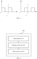
- FIG. 3 is a schematic diagram of a waveform of a pulse current according to an embodiment of the present disclosure. As illustrated in FIG. 3 , the drawing a of FIG. 3 shows a waveform of a pulse current output by the power battery, and the drawing b of FIG. 3 shows a waveform of a pulse current output by the supercapacitor.
- the pulse control unit determines the frequency and the amplitude of the pulse current based on the temperature value and the SOC value, and sends the frequency and the amplitude to the power battery.
- the power battery outputs a rectangular pulse current having the corresponding frequency and amplitude.
- the pulse control unit controls and adjusts the direction of the pulse current to enable the supercapacitor to output a rectangular pulse current to the power battery, and enable the pulse control unit to adjust the frequency and amplitude of the rectangular pulse current output from the supercapacitor.
- the pulse control unit adjusts a direction of the rectangular pulse current again to allow the power battery to output a rectangular pulse current to the supercapacitor. The above process is repeated to complete the heating for the power battery.
- control method when the temperature value is higher than or equal to the predetermined temperature threshold or the SOC value is lower than or equal to the predetermined charge threshold, the control method further includes: issuing a stop heating instruction to the pulse control unit to control, by the pulse control unit, to stop heating the power battery.
- the thermal management controller acquires the temperature value of the power battery in real time, and the thermal management controller sends the temperature value to the heating control unit.
- the power battery may also send the current SOC value to the heating control unit in real time.
- the heating control unit detects that the temperature value is higher than or equal to the predetermined temperature threshold, or the SOC value is lower than or equal to the predetermined charge threshold, the heating control unit issues the stop heating instruction to the pulse control unit. After receiving the stop heating instruction, the pulse control unit controls the power battery and the supercapacitor to stop outputting the pulse current, thereby stopping heating the power battery.
- the heating control unit detects that the temperature value is higher than or equal to the predetermined temperature threshold, it indicates that the current temperature value of the power battery has reached the required temperature value.
- the SOC value is lower than or equal to the predetermined charge threshold, it means that the residual charge of the power battery can no longer support the heating process of the power battery. Therefore, in the two cases, it is necessary to stop heating the power battery.
- control method further includes: controlling the supercapacitor to supply power to a low-voltage onboard electrical device after the heating for the power battery is stopped.
- electrical energy output by discharging of the power battery may be stored in the supercapacitor.
- the DC/DC converter can be used to convert the electrical energy stored in the supercapacitor into 12V low voltage, and then output the electrical energy to the low-voltage onboard electrical device, so as to power the low-voltage onboard electrical device by use of the supercapacitor. In this way, the utilization rate of electrical energy can be improved and energy waste of a whole vehicle system can be reduced.
- control method for the battery heating system is described below with a specific example.
- the heating control unit After the whole vehicle is powered on, the heating control unit detects whether the power battery, the supercapacitor, the thermal management controller, and the pulse control unit are in a normal state. If the above devices are in the normal state, the heating control unit may send a heating request to the thermal management controller and the power battery.
- the thermal management controller After receiving the request of heating, acquires a temperature value of the power battery and sends the temperature value to the heating control unit. After receiving the request of heating, the power battery may send a current SOC value to the heating control unit. When the temperature value is lower than the predetermined temperature threshold and the SOC value is higher than the predetermined charge threshold, the heating control unit issues a heating instruction to the pulse control unit.
- the pulse control unit After receiving the heating instruction, the pulse control unit determines a frequency and an amplitude of a pulse current based on the temperature value and the SOC value, and then sends the frequency and the amplitude to the power battery. After receiving the frequency and the amplitude, the power battery outputs a rectangular pulse current having a corresponding frequency and amplitude. The rectangular pulse current flows to the supercapacitor through the pulse control unit to discharge the power battery. After half a cycle, the pulse control unit adjusts the direction of the pulse current to allow the supercapacitor to output a rectangular pulse current to the power battery.
- the heating control unit When the heating control unit detects that the current temperature value of the power battery is higher than the predetermined temperature threshold or the current SOC value of the power battery is lower than the predetermined charge threshold, the heating control unit issues a stop heating instruction to the pulse control unit, to stop heating the power battery by controlling the pulse control unit.
- the DC/DC converter is used to convert the electrical energy stored in the supercapacitor into the 12V low voltage, and then the electrical energy is output to a low-voltage onboard electrical device to supply power to the low-voltage onboard electrical device.
- the pulse control unit controls the pulse control unit to realize the heating for the power battery.
- excessive electrical energy output during the heating process is stored by the supercapacitor.
- the stored electrical energy can further supply power to the low-voltage onboard electrical device. Therefore, consumption of electrical energy in the heating process of the power battery is reduced, and the utilization rate of electrical energy is improved, which reduces the energy waste of the whole vehicle system, improves the endurance mileage of the whole vehicle under the low temperature condition, and thereby enhancing the user experience.
- FIG. 4 is a block diagram of a battery heating system according to another embodiment of the present disclosure.
- a battery heating system 400 includes a supercapacitor 410; a heating control unit 420 configured to obtain a temperature value and an SOC value of a power battery and issue a heating instruction when the temperature value is lower than a predetermined temperature threshold and the SOC value is higher than a predetermined charge threshold; and a pulse control unit 430 configured to control, based on the heating instruction, bi-directional energy flow between the power battery and the supercapacitor 410 by means of a pulse current, so as to heat the power battery.
- the heating control unit 420 by means of the heating control unit 420, the temperature value and the SOC value of the power battery are obtained.
- the heating instruction is issued when the temperature value is lower than a predetermined temperature threshold and the SOC value is higher than a predetermined charge threshold.
- the pulse control unit 430 based on the heating instruction, the bi-directional energy flow between the power battery and the supercapacitor 410 is controlled to be performed by means of the pulse current, to heat the power battery. Therefore, the electrical energy output by the power battery can be stored in the supercapacitor 410, which improves the utilization rate of the electric energy, reduces the energy waste of the whole vehicle system, and improves the endurance mileage of the whole vehicle under the low temperature condition, thereby enhancing the user experience.
- the energy between the power battery and the supercapacitor 410 flows alternately.
- the pulse control unit 430 is configured to, in each and every heating cycle, firstly control the power battery to output the pulse current to the supercapacitor 410, and whereafter control the supercapacitor 410 to output the pulse current to the power battery.
- the pulse control unit 430 is further configured to determine an amplitude and a frequency of the pulse current based on the temperature value and the SOC value of the power battery.
- the heating control unit 420 is further configured to issue a stop heating instruction to the pulse control unit 430 to control, by the pulse control unit 430, to stop heating the power battery, when the temperature value is higher than or equal to the predetermined temperature threshold or the SOC value is lower than or equal to the predetermined charge threshold.
- the heating control unit 420 is further configured to control the supercapacitor 410 to supply power to a low-voltage onboard electrical device after the heating for the power battery is stopped.
- the present disclosure further provides an electric vehicle.
- the electric vehicle includes the battery heating system according to the above-described embodiments.
- the logical and/or steps described in the flowchart or otherwise depicted herein, for example, may be considered as a fixed sequence list of executable instructions for implementing logical functions, and may be specifically implemented in any computer-readable medium for use for, or in conjunction with, an instruction execution system, apparatus, or device, such as a computer-based system, a system including a processor, or other systems that may fetch and execute instructions from the instruction execution system, apparatus, or device.
- the "computer-readable medium” may be any apparatus that can include, store, communicate, propagate, or transport the program for use for or in conjunction with the instruction execution system, apparatus, or device.
- the computer-readable medium includes: an electrical connection portion (an electrical device) having one or more of wires, a portable computer disk cartridge (a magnetic device), a random access memory (RAM), a read-only memory (ROM), an erasable programmable read-only memory (EPROM or Flash memory), an optical apparatus, and a portable compact disc read-only memory (CD-ROM).
- the computer-readable mediums may even be paper or other suitable mediums on which the program may be printed, since the program may be obtained electronically by, for example, optical scanning of the paper or other mediums followed by editing, interpretation or other suitable processing if necessary, and then stored in a computer memory.
- each part of the present disclosure can be implemented in hardware, software, firmware or any combination thereof.
- multiple steps or methods can be implemented using software or firmware stored in a memory and executed by a suitable instruction execution system.
- a suitable instruction execution system For example, when implemented in hardware, as in another embodiment, it can be implemented by any one or combination of the following technologies known in the art: a discrete logic circuit having logic gate circuits for implementing logic functions on data signals, an application-specific integrated circuit with suitable combined logic gates, a Programmable Gate Array (PGA), a Field Programmable Gate Array (FPGA), etc.
- PGA Programmable Gate Array
- FPGA Field Programmable Gate Array
- first and second are only used for descriptive purposes, and cannot be understood as indicating or implying relative importance or implicitly indicating the number of indicated technical features. Therefore, the features associated with “first” and “second” may explicitly or implicitly include at least one of the features. In the description of the present disclosure, “plurality” means at least two, such as two, three, unless otherwise specifically defined.
- the first feature "on” or “under” the second feature may mean that the first feature is in direct contact with the second feature, or the first and second features are in indirect contact through an intermediate.
- the first feature "above” the second feature means that the first feature is directly above or obliquely above the second feature, or simply means that the level of the first feature is higher than that of the second feature.
- the first feature "below” the second feature may mean that the first feature is directly below or obliquely below the second feature, or simply mean that the level of the first feature is lower than that of the second feature.
Landscapes
- Engineering & Computer Science (AREA)
- Power Engineering (AREA)
- Transportation (AREA)
- Mechanical Engineering (AREA)
- General Chemical & Material Sciences (AREA)
- Manufacturing & Machinery (AREA)
- Chemical & Material Sciences (AREA)
- Chemical Kinetics & Catalysis (AREA)
- Electrochemistry (AREA)
- Sustainable Energy (AREA)
- Sustainable Development (AREA)
- Life Sciences & Earth Sciences (AREA)
- Automation & Control Theory (AREA)
- Physics & Mathematics (AREA)
- Electromagnetism (AREA)
- Secondary Cells (AREA)
- Electric Propulsion And Braking For Vehicles (AREA)
Applications Claiming Priority (2)
| Application Number | Priority Date | Filing Date | Title |
|---|---|---|---|
| CN202211599149.7A CN115966812A (zh) | 2022-12-12 | 2022-12-12 | 电池加热系统的控制方法及电池加热系统、电动车辆 |
| PCT/CN2023/093313 WO2024124788A1 (zh) | 2022-12-12 | 2023-05-10 | 电池加热系统的控制方法及电池加热系统、电动车辆 |
Publications (2)
| Publication Number | Publication Date |
|---|---|
| EP4576335A1 true EP4576335A1 (de) | 2025-06-25 |
| EP4576335A4 EP4576335A4 (de) | 2026-01-14 |
Family
ID=87359391
Family Applications (1)
| Application Number | Title | Priority Date | Filing Date |
|---|---|---|---|
| EP23902001.9A Pending EP4576335A4 (de) | 2022-12-12 | 2023-05-10 | Steuerungsverfahren für batterieerwärmungssystem sowie batterieerwärmungssystem und elektrofahrzeug |
Country Status (6)
| Country | Link |
|---|---|
| US (1) | US20250229672A1 (de) |
| EP (1) | EP4576335A4 (de) |
| JP (1) | JP2025530356A (de) |
| KR (1) | KR20250050084A (de) |
| CN (1) | CN115966812A (de) |
| WO (1) | WO2024124788A1 (de) |
Families Citing this family (4)
| Publication number | Priority date | Publication date | Assignee | Title |
|---|---|---|---|---|
| CN115966812A (zh) * | 2022-12-12 | 2023-04-14 | 浙江极氪智能科技有限公司 | 电池加热系统的控制方法及电池加热系统、电动车辆 |
| CN118970294B (zh) * | 2024-10-18 | 2025-02-11 | 成都鹰明智通科技股份有限公司 | 一种换电电池串联加热控制方法及系统 |
| CN120065017A (zh) * | 2024-11-13 | 2025-05-30 | 北京卡文新能源汽车有限公司 | 脉冲电流的计算方法、装置、存储介质和电子设备 |
| CN119821239B (zh) * | 2025-01-23 | 2025-11-04 | 奇瑞新能源汽车股份有限公司 | 车辆动力电池的加热方法、装置及存储介质 |
Family Cites Families (15)
| Publication number | Priority date | Publication date | Assignee | Title |
|---|---|---|---|---|
| FR2936110B1 (fr) * | 2008-09-16 | 2010-10-01 | Commissariat Energie Atomique | Systeme autonome comportant une batterie et une supercapacite et procede de charge. |
| CN103222105B (zh) * | 2010-11-05 | 2015-08-26 | 三菱电机株式会社 | 充放电装置及充放电控制方法 |
| JP2014090639A (ja) * | 2012-10-31 | 2014-05-15 | Daihatsu Motor Co Ltd | 車両用充電制御システム |
| JP6094389B2 (ja) * | 2013-06-07 | 2017-03-15 | 住友電気工業株式会社 | 電源装置及び電気推進車両並びに二次電池の昇温方法 |
| JP2017216785A (ja) * | 2016-05-30 | 2017-12-07 | 株式会社リコー | 電源システム、移動体、及び制御方法 |
| CN110828918B (zh) * | 2019-11-13 | 2023-03-24 | 奇瑞新能源汽车股份有限公司 | 一种汽车动力电池的控制系统及控制方法 |
| CN111845379B (zh) * | 2020-04-15 | 2022-08-02 | 浙江吉智新能源汽车科技有限公司 | 一种电动汽车的能量控制方法、装置及系统 |
| CN113745702B (zh) * | 2020-05-29 | 2023-05-09 | 比亚迪股份有限公司 | 电动汽车及其动力电池的加热方法、装置和存储介质 |
| CN113745701B (zh) * | 2020-05-29 | 2024-08-06 | 比亚迪股份有限公司 | 动力电池的加热方法和装置、控制器和车辆 |
| CN112510272B (zh) * | 2020-12-03 | 2022-09-06 | 国创移动能源创新中心(江苏)有限公司 | 一种基于超级电容的储能式动力电池加热设备 |
| CN113206325B (zh) * | 2021-04-30 | 2022-05-03 | 重庆长安新能源汽车科技有限公司 | 一种动力电池内外部联合加热方法 |
| CN113085659B (zh) * | 2021-04-30 | 2022-05-31 | 重庆长安新能源汽车科技有限公司 | 一种电动汽车、动力电池脉冲加热系统及加热方法 |
| CN115366743B (zh) * | 2022-04-24 | 2024-02-02 | 宁德时代新能源科技股份有限公司 | 动力电池的加热方法、装置、电子设备、系统及存储介质 |
| CN115347275B (zh) * | 2022-07-26 | 2025-10-17 | 西安迅湃快速充电技术有限公司 | 一种基于超级电容的动力电池加热系统及方法 |
| CN115966812A (zh) * | 2022-12-12 | 2023-04-14 | 浙江极氪智能科技有限公司 | 电池加热系统的控制方法及电池加热系统、电动车辆 |
-
2022
- 2022-12-12 CN CN202211599149.7A patent/CN115966812A/zh active Pending
-
2023
- 2023-05-10 JP JP2025515539A patent/JP2025530356A/ja active Pending
- 2023-05-10 EP EP23902001.9A patent/EP4576335A4/de active Pending
- 2023-05-10 WO PCT/CN2023/093313 patent/WO2024124788A1/zh not_active Ceased
- 2023-05-10 KR KR1020257008413A patent/KR20250050084A/ko active Pending
-
2025
- 2025-04-02 US US19/097,887 patent/US20250229672A1/en active Pending
Also Published As
| Publication number | Publication date |
|---|---|
| US20250229672A1 (en) | 2025-07-17 |
| JP2025530356A (ja) | 2025-09-11 |
| WO2024124788A1 (zh) | 2024-06-20 |
| EP4576335A4 (de) | 2026-01-14 |
| CN115966812A (zh) | 2023-04-14 |
| KR20250050084A (ko) | 2025-04-14 |
Similar Documents
| Publication | Publication Date | Title |
|---|---|---|
| EP4576335A1 (de) | Steuerungsverfahren für batterieerwärmungssystem sowie batterieerwärmungssystem und elektrofahrzeug | |
| US9573476B2 (en) | Method and apparatus for controller wakeup using control pilot signal from charge port | |
| CN106183860B (zh) | 车辆充电方法、装置及整车控制器远程控制策略 | |
| CN107962954B (zh) | 混合动力车辆的变流器控制装置及其方法 | |
| EP4365015A1 (de) | Fahrzeugsteuerungsverfahren und -vorrichtung und fahrzeug | |
| US9346369B2 (en) | Charging device | |
| CN103475072A (zh) | 用于车载电池充电器的控制导向唤醒电路 | |
| CN105978087A (zh) | 车辆的低压蓄电池充电控制方法、装置和车辆 | |
| KR102699015B1 (ko) | 차량용 저전압 직류 컨버터 제어 시스템 및 방법 | |
| CN113054288A (zh) | 车辆及其电池加热方法和系统 | |
| CN112124142B (zh) | 电动车辆 | |
| US20220297563A1 (en) | Auxiliary Battery System for Vehicle | |
| CN114987207B (zh) | 一种上下电模式的切换控制方法、装置、电子设备及介质 | |
| US10186882B2 (en) | Battery pack and method of driving the same | |
| CN118003926A (zh) | 车辆充电的控制方法、装置、存储介质及车辆 | |
| WO2024045685A1 (zh) | 车载多蓄电池的充电控制方法、系统及介质 | |
| CN114684001A (zh) | 车灯控制装置和方法 | |
| KR20240011537A (ko) | 배터리 프리컨디셔닝 진입 여부 판단을 위한 정보 제공 방법 및 시스템 | |
| US12214771B2 (en) | Engine control method, system, and vehicle | |
| CN105383420B (zh) | 利用瞬间操作提供升压电压 | |
| JP2010220279A (ja) | 電源制御装置及び方法 | |
| EP2437139A1 (de) | Verfahren und Vorrichtung zur Stromverwaltung | |
| US20250083567A1 (en) | Battery heating control method and control device | |
| CN106451586A (zh) | 环境友好型车辆的充电装置 | |
| CN116766970A (zh) | 充电电路、控制导引电路和充电控制方法 |
Legal Events
| Date | Code | Title | Description |
|---|---|---|---|
| STAA | Information on the status of an ep patent application or granted ep patent |
Free format text: STATUS: THE INTERNATIONAL PUBLICATION HAS BEEN MADE |
|
| PUAI | Public reference made under article 153(3) epc to a published international application that has entered the european phase |
Free format text: ORIGINAL CODE: 0009012 |
|
| STAA | Information on the status of an ep patent application or granted ep patent |
Free format text: STATUS: REQUEST FOR EXAMINATION WAS MADE |
|
| 17P | Request for examination filed |
Effective date: 20250317 |
|
| AK | Designated contracting states |
Kind code of ref document: A1 Designated state(s): AL AT BE BG CH CY CZ DE DK EE ES FI FR GB GR HR HU IE IS IT LI LT LU LV MC ME MK MT NL NO PL PT RO RS SE SI SK SM TR |
|
| A4 | Supplementary search report drawn up and despatched |
Effective date: 20251215 |
|
| DAV | Request for validation of the european patent (deleted) | ||
| DAX | Request for extension of the european patent (deleted) |