EP4575358A2 - Kühlschrank - Google Patents
Kühlschrank Download PDFInfo
- Publication number
- EP4575358A2 EP4575358A2 EP25175062.6A EP25175062A EP4575358A2 EP 4575358 A2 EP4575358 A2 EP 4575358A2 EP 25175062 A EP25175062 A EP 25175062A EP 4575358 A2 EP4575358 A2 EP 4575358A2
- Authority
- EP
- European Patent Office
- Prior art keywords
- ice
- tray
- water supply
- ice making
- water
- Prior art date
- Legal status (The legal status is an assumption and is not a legal conclusion. Google has not performed a legal analysis and makes no representation as to the accuracy of the status listed.)
- Pending
Links
Images


Classifications
-
- F—MECHANICAL ENGINEERING; LIGHTING; HEATING; WEAPONS; BLASTING
- F25—REFRIGERATION OR COOLING; COMBINED HEATING AND REFRIGERATION SYSTEMS; HEAT PUMP SYSTEMS; MANUFACTURE OR STORAGE OF ICE; LIQUEFACTION SOLIDIFICATION OF GASES
- F25C—PRODUCING, WORKING OR HANDLING ICE
- F25C1/00—Producing ice
- F25C1/18—Producing ice of a particular transparency or translucency, e.g. by injecting air
-
- F—MECHANICAL ENGINEERING; LIGHTING; HEATING; WEAPONS; BLASTING
- F25—REFRIGERATION OR COOLING; COMBINED HEATING AND REFRIGERATION SYSTEMS; HEAT PUMP SYSTEMS; MANUFACTURE OR STORAGE OF ICE; LIQUEFACTION SOLIDIFICATION OF GASES
- F25C—PRODUCING, WORKING OR HANDLING ICE
- F25C1/00—Producing ice
- F25C1/22—Construction of moulds; Filling devices for moulds
- F25C1/24—Construction of moulds; Filling devices for moulds for refrigerators, e.g. freezing trays
-
- F—MECHANICAL ENGINEERING; LIGHTING; HEATING; WEAPONS; BLASTING
- F25—REFRIGERATION OR COOLING; COMBINED HEATING AND REFRIGERATION SYSTEMS; HEAT PUMP SYSTEMS; MANUFACTURE OR STORAGE OF ICE; LIQUEFACTION SOLIDIFICATION OF GASES
- F25C—PRODUCING, WORKING OR HANDLING ICE
- F25C1/00—Producing ice
- F25C1/22—Construction of moulds; Filling devices for moulds
- F25C1/25—Filling devices for moulds
-
- F—MECHANICAL ENGINEERING; LIGHTING; HEATING; WEAPONS; BLASTING
- F25—REFRIGERATION OR COOLING; COMBINED HEATING AND REFRIGERATION SYSTEMS; HEAT PUMP SYSTEMS; MANUFACTURE OR STORAGE OF ICE; LIQUEFACTION SOLIDIFICATION OF GASES
- F25C—PRODUCING, WORKING OR HANDLING ICE
- F25C5/00—Working or handling ice
- F25C5/02—Apparatus for disintegrating, removing or harvesting ice
- F25C5/04—Apparatus for disintegrating, removing or harvesting ice without the use of saws
- F25C5/08—Apparatus for disintegrating, removing or harvesting ice without the use of saws by heating bodies in contact with the ice
-
- F—MECHANICAL ENGINEERING; LIGHTING; HEATING; WEAPONS; BLASTING
- F25—REFRIGERATION OR COOLING; COMBINED HEATING AND REFRIGERATION SYSTEMS; HEAT PUMP SYSTEMS; MANUFACTURE OR STORAGE OF ICE; LIQUEFACTION SOLIDIFICATION OF GASES
- F25C—PRODUCING, WORKING OR HANDLING ICE
- F25C2400/00—Auxiliary features or devices for producing, working or handling ice
- F25C2400/10—Refrigerator units
-
- F—MECHANICAL ENGINEERING; LIGHTING; HEATING; WEAPONS; BLASTING
- F25—REFRIGERATION OR COOLING; COMBINED HEATING AND REFRIGERATION SYSTEMS; HEAT PUMP SYSTEMS; MANUFACTURE OR STORAGE OF ICE; LIQUEFACTION SOLIDIFICATION OF GASES
- F25C—PRODUCING, WORKING OR HANDLING ICE
- F25C2400/00—Auxiliary features or devices for producing, working or handling ice
- F25C2400/14—Water supply
-
- F—MECHANICAL ENGINEERING; LIGHTING; HEATING; WEAPONS; BLASTING
- F25—REFRIGERATION OR COOLING; COMBINED HEATING AND REFRIGERATION SYSTEMS; HEAT PUMP SYSTEMS; MANUFACTURE OR STORAGE OF ICE; LIQUEFACTION SOLIDIFICATION OF GASES
- F25C—PRODUCING, WORKING OR HANDLING ICE
- F25C2600/00—Control issues
- F25C2600/04—Control means
-
- F—MECHANICAL ENGINEERING; LIGHTING; HEATING; WEAPONS; BLASTING
- F25—REFRIGERATION OR COOLING; COMBINED HEATING AND REFRIGERATION SYSTEMS; HEAT PUMP SYSTEMS; MANUFACTURE OR STORAGE OF ICE; LIQUEFACTION SOLIDIFICATION OF GASES
- F25C—PRODUCING, WORKING OR HANDLING ICE
- F25C2700/00—Sensing or detecting of parameters; Sensors therefor
- F25C2700/04—Level of water
-
- F—MECHANICAL ENGINEERING; LIGHTING; HEATING; WEAPONS; BLASTING
- F25—REFRIGERATION OR COOLING; COMBINED HEATING AND REFRIGERATION SYSTEMS; HEAT PUMP SYSTEMS; MANUFACTURE OR STORAGE OF ICE; LIQUEFACTION SOLIDIFICATION OF GASES
- F25C—PRODUCING, WORKING OR HANDLING ICE
- F25C2700/00—Sensing or detecting of parameters; Sensors therefor
- F25C2700/12—Temperature of ice trays
Definitions
- the controller may control the water supply valve so that the ice making starts when the water supply amount to the ice making cell reaches the target water supply amount, and the second tray moves again to the water supply position to supply water as much as an additional water supply amount less than the reference water supply amount when the water supply amount to the ice making cell does not reach the target water supply amount.
- the reference water supply amount may be set differently according to a water supply water pressure determined in the water supply process.
- the controller may control the ice making to start, and when the water supply amount to the ice making cell does not reach the target water supply amount, the additional water supply as much as the additional water supply amount may be repetitively performed until the water supply amount to the ice making cell reaches the target water supply amount.
- the controller may control the second tray to move to an ice separation position in a forward direction so as to take ice out of the ice making cell and then move in a reverse direction after the generation of the ice in the ice making cell is completed.
- the controller may control the second tray to move to the water supply position in the reverse direction after the ice separation is completed so as to supply the water.
- the water supply amount detection part may include a temperature sensor configured to detect a temperature of the ice making cell.
- the controller may control the water supply valve so that the water as much as the reference water supply amount is supplied to the ice making cell if a temperature detected by the temperature sensor reaches a water supply start temperature.
- the controller may control the water supply valve so that the water as much as the additional water supply amount is supplied to the ice making cell if a temperature detected by the temperature sensor reaches a water supply start temperature.
- the water supply amount detection part may include a capacitive sensor that outputs different signals according to whether the ice making cell is in contact with water.
- a first signal When the capacitive sensor is in contact with the water, a first signal may be output, and when the capacitive sensor is not in contact with the water, a second signal may be output.
- the controller may determine that the water supply amount to the ice making cell reaches the target water supply amount when the first signal is output from the capacitive sensor.
- the refrigerator may further include a heater configured to provide heat to the ice making cell.
- the controller may control the heater to be turned on in at least partial section while the cooler supplies the cold so that bubbles dissolved in the water within the ice making cell moves from a portion, at which the ice is generated, toward the water that is in a liquid state to generate transparent ice.
- the controller may control one or more of cooling power of the cooler, a heating amount of the heater to vary according to a mass per unit height of water within the ice making cell.
- a method for controlling a refrigerator relates to a method for controlling a refrigerator, which includes a storage chamber configured to store food, a cooler configured to supply cold, a first tray configured to define one portion of an ice making cell that is a space in which water is phase-changed into ice by the cold, a second tray configured to define the other portion of the ice making cell, the second tray being in contact with the first tray in an ice making process and being spaced apart from the first tray in an ice separation process, a water supply valve configured to adjust a flow of the water supplied to the ice making cell, a water supply amount detection part configured to detect a water supply amount to the ice making cell, and a controller configured to control the water supply valve.
- the controller may determine whether the water supply water pressure is less than a reference water pressure.
- the reference water supply amount may be set as a first reference water supply amount, and when the water pressure is less than the reference water pressure, the reference water supply amount may be set as a second reference water supply amount less than the first reference water supply amount.
- the additional water supply amount when the water pressure is low may be set to be greater than the additional water supply amount when the water pressure is high.
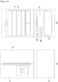
- the cabinet 14 is provided with a duct supplying cold air to the ice maker 200.
- the duct guides the cold air heat-exchanged with a refrigerant flowing through the evaporator to the ice maker 200.
- the duct may be disposed behind the cabinet 14 to discharge the cold air toward a front side of the cabinet 14.
- the ice maker 200 may be disposed at a front side of the duct.
- a discharge hole of the duct may be provided in one or more of a rear wall and an upper wall of the freezing compartment 32.
- a space in which the ice maker 200 is disposed is not limited to the freezing compartment 32.
- the ice maker 200 may be disposed in various spaces as long as the ice maker 200 receives the cold air.
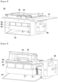
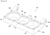
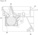
- FIG. 2 is a perspective view of the ice maker according to an embodiment
- FIG. 3 is a perspective view illustrating a state in which the bracket is removed from the ice maker of FIG. 2
- FIG. 4 is an exploded perspective view of the ice maker according to an embodiment.
- each component of the ice maker 200 may be provided inside or outside the bracket 220, and thus, the ice maker 200 may constitute one assembly.
- the bracket 220 may be installed at, for example, the upper wall of the freezing compartment 32.
- the water supply part 240 may be installed on an upper side of an inner surface of the bracket 220.
- the water supply part 240 may be provided with an opening in each of an upper side and a lower side to guide water, which is supplied to an upper side of the water supply part 240, to a lower side of the water supply part 240.
- the upper opening of the water supply part 240 may be greater than the lower opening to limit a discharge range of water guided downward through the water supply part 240.
- a water supply pipe through which water is supplied may be installed to the upper side of the water supply part 240. The water supplied to the water supply part 240 may move downward.
- the water supply part 240 may prevent the water discharged from the water supply pipe from dropping from a high position, thereby preventing the water from splashing. Since the water supply part 240 is disposed below the water supply pipe, the water may be guided downward without splashing up to the water supply part 240, and an amount of splashing water may be reduced even if the water moves downward due to the lowered height.
- the ice maker 200 may include a first tray assembly and a second tray assembly.
- the first tray assembly may include a first tray 320, a first tray case, or all of the first tray 320 and a first tray case.
- the second tray assembly may include a second tray 380, a second tray case, or all of the second tray 380 and a second tray case.
- the bracket 220 may define at least a portion of a space that accommodates the first tray assembly and the second tray assembly.
- the ice maker 200 may include an ice making cell 320a (see FIG. 11 ) in which water is phase-changed into ice by the cold air.
- the first tray 320 may form at least a portion of the ice making cell 320a.
- the second tray 380 may form the other portion of the ice making cell 320a.
- the second tray 380 may be disposed to be relatively movable with respect to the first tray 320.
- the second tray 380 may linearly rotate or rotate.
- the rotation of the second tray 380 will be described as an example.
- the first tray 320 and the second tray 380 may be arranged in a vertical direction in a state in which the ice making cell 320a is defined. Accordingly, the first tray 320 may be referred to as an upper tray, and the second tray 380 may be referred to as a lower tray.
- a plurality of ice making cells 320a may be defined by the first tray 320 and the second tray 380.
- the ice making cell 320a When water is cooled by cold air while water is supplied to the ice making cell 320a, ice having the same or similar shape as that of the ice making cell 320a may be made.
- the ice making cell 320a may be provided in a spherical shape or a shape similar to a spherical shape.
- the ice making cell 320a may have a rectangular parallelepiped shape or a polygonal shape.
- the first tray case may include the first tray supporter 340 and the first tray cover 300.
- the first tray supporter 340 and the first tray cover 300 may be integrally provided or coupled to each other with each other after being manufactured in separate configurations.
- at least a portion of the first tray cover 300 may be disposed above the first tray 320.
- At least a portion of the first tray supporter 340 may be disposed under the first tray 320.
- the first tray cover 300 may be manufactured as a separate part from the bracket 220 and then may be coupled to the bracket 220 or integrally formed with the bracket 220. That is, the first tray case may include the bracket 220.
- a spring 402 may be connected to one side of the second tray supporter 400.
- the spring 402 may provide elastic force to the second tray supporter 400 to maintain a state in which the second tray 380 contacts the first tray 320.
- the ice maker 200 may further include a second heater case 420.
- a transparent ice heater 430 may be installed in the second heater case 420.
- the second heater case 420 may be integrally formed with the second tray supporter 400 or may be separately provided to be coupled to the second tray supporter 400.
- the transparent ice heater 430 will be described in detail.
- the controller 800 may control the transparent ice heater 430 so that heat is supplied to the ice making cell 320a in at least partial section while cold air is supplied to the ice making cell 320a to make the transparent ice.
- An ice making rate may be delayed so that bubbles dissolved in water within the ice making cell 320a may move from a portion at which ice is made toward liquid water by the heat of the transparent ice heater 430, thereby making transparent ice in the ice maker 200. That is, the bubbles dissolved in water may be induced to escape to the outside of the ice making cell 320a or to be collected into a predetermined position in the ice making cell 320a.
- a cold air supply part 900 to be described later supplies cold air to the ice making cell 320a, if the ice making rate is high, the bubbles dissolved in the water inside the ice making cell 320a may be frozen without moving from the portion at which the ice is made to the liquid water, and thus, transparency of the ice may be reduced.
- the cold air supply part 900 supplies the cold air to the ice making cell 320a, if the ice making rate is low, the above limitation may be solved to increase in transparency of the ice.
- an ice making time increases.
- the transparent ice heater 430 may be disposed at one side of the ice making cell 320a so that the heater locally supplies heat to the ice making cell 320a, thereby increasing in transparency of the made ice while reducing the ice making time.
- the ice maker 200 may further include a driver 480 that provides driving force.
- the second tray 380 may relatively move with respect to the first tray 320 by receiving the driving force of the driver 480.
- the first pusher 260 may move by receiving the driving force of the driving force 480.
- a water supply position and an ice making position may be distinguished and determined based on the signals outputted from the sensor.
- the ice maker 200 may further include a second pusher 540.
- the second pusher 540 may be installed on the bracket 220.
- the second pusher 540 may include at least one pushing bar 544.
- the second pusher 540 may include a pushing bar 544 provided with the same number as the number of ice making cells 320a, but is not limited thereto.
- the pushing bar 544 may push the ice disposed in the ice making cell 320a.
- the pushing bar 544 may pass through the second tray supporter 400 to contact the second tray 380 defining the ice making cell 320a and then press the contacting second tray 380. Therefore, the second tray supporter 400 may be provided with a lower opening 406b (see FIG. 10 ) through which a portion of the second pusher 540 passes.
- the first tray supporter 300 may be rotatably coupled to the second tray supporter 400 with respect to the second tray supporter 400 and then be disposed to change in angle about the shaft 440.
- the second tray 380 may be made of a non-metal material.
- the second tray 380 when the second tray 380 is pressed by the second pusher 540, the second tray 380 may be made of a flexible or soft material which is deformable.
- the second tray 380 may be made of, for example, a silicon material.
- pressing force of the second pusher 540 may be transmitted to ice.
- the ice and the second tray 380 may be separated from each other by the pressing force of the second pusher 540.
- the coupling force or attaching force between the ice and the second tray 380 may be reduced, and thus, the ice may be easily separated from the second tray 380.
- the second tray 380 is made of the non-metallic material and the flexible or soft material, after the shape of the second tray 380 is deformed by the second pusher 540, when the pressing force of the second pusher 540 is removed, the second tray 380 may be easily restored to its original shape.
- the first tray 320 may be made of a metal material.
- the ice maker 200 since the coupling force or the attaching force between the first tray 320 and the ice is strong, the ice maker 200 according to this embodiment may include at least one of the ice separation heater 290 or the first pusher 260.
- the first tray 320 may be made of a non-metallic material.
- the ice maker 200 may include only one of the ice separation heater 290 and the first pusher 260.
- the ice maker 200 may not include the ice separation heater 290 and the first pusher 260.
- the first tray 320 may be made of, for example, a silicon material. That is, the first tray 320 and the second tray 380 may be made of the same material.
- the first tray 320 and the second tray 380 may have different hardness to maintain sealing performance at the contact portion between the first tray 320 and the second tray 380.
- the second tray 380 since the second tray 380 is pressed by the second pusher 540 to be deformed, the second tray 380 may have hardness less than that of the first tray 320 to facilitate the deformation of the second tray 380.
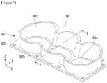
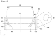
- FIG. 5 is a perspective view of the first tray when viewed from a lower side according to an embodiment of the present invention
- FIG. 6 is a cross-sectional view of the first tray according to an embodiment of the present invention.
- the first tray 320 may define a first cell 321a that is a portion of the ice making cell 320a.
- the first tray 320 may include a first tray wall 321 defining a portion of the ice making cell 320a.
- the first tray 320 may define a plurality of first cells 321a.
- the plurality of first cells 321a may be arranged in a line.
- the plurality of first cells 321a may be arranged in an X-axis direction in FIG. 5 .
- the first tray wall 321 may define the plurality of first cells 321a.
- the first tray wall 321 may include a plurality of first cell walls 3211 that respectively define the plurality of first cells 321a, and a connection wall 3212 connecting the plurality of first cell walls 3211 to each other.
- the first tray wall 321 may be a wall extending in the vertical direction.
- the first tray 320 may include an opening 324.
- the opening 324 may communicate with the first cell 321a.
- the opening 324 may allow the cold air to be supplied to the first cell 321a.
- the opening 324 may allow water for making ice to be supplied to the first cell 321a.
- the opening 234 may provide a passage through which a portion of the first pusher 260 passes. For example, in the ice separation process, a portion of the first pusher 260 may be inserted into the ice making cell 320a through the opening 234.
- the first tray 320 may include a plurality of openings 324 corresponding to the plurality of first cells 321a.
- One of the plurality of openings 324 324a may provide a passage of the cold air, a passage of the water, and a passage of the first pusher 260. In the ice making process, the bubbles may escape through the opening 324.
- the first tray 320 may further include an auxiliary storage chamber 325 communicating with the ice making cell 320a.
- the auxiliary storage chamber 325 may store water overflowed from the ice making cell 320a.
- the ice expanded in a process of phase-changing the supplied water may be disposed in the auxiliary storage chamber 325. That is, the expanded ice may pass through the opening 324 and be disposed in the auxiliary storage chamber 325.
- the auxiliary storage chamber 325 may be defined by a storage chamber wall 325a.
- the storage chamber wall 325a may extend upwardly around the opening 324.
- the storage chamber wall 325a may have a cylindrical shape or a polygonal shape.
- the first pusher 260 may pass through the opening 324 after passing through the storage chamber wall 325a.
- the storage chamber wall 325a may define the auxiliary storage chamber 325 and also reduce deformation of the periphery of the opening 324 in the process in which the first pusher 260 passes through the opening 324 during the ice separation process.
- the first tray 320 may include a first contact surface 322c contacting the second tray 380.
- the first tray 320 may further include a first extension wall 327 extending in the horizontal direction from the first tray wall 321.
- the first extension wall 327 may extend in the horizontal direction around an upper end of the first extension wall 327.
- One or more first coupling holes 327a may be provided in the first extension wall 327.
- the plurality of first coupling holes 327a may be arranged in one or more axes of the X axis and the Y axis.
- the "central line” is a line passing through a volume center of the ice making cell 320a or a center of gravity of water or ice in the ice making cell 320a regardless of the axial direction.
- the first tray 320 may include a first portion 322 that defines a portion of the ice making cell 320a.
- the first portion 322 may be a portion of the first tray wall 321.
- the first tray wall 321 may include one portion of the second extension part 323b of each of the first portion 322 and the second portion 323.
- the first extension wall 327 may include the other portion of each of the first extension part 323a and the second extension part 323b.
- the predetermined point of the first portion 382 may be one end of the first portion 382.
- the predetermined point of the first portion 382 may be one point of the second contact surface 382c.
- the second portion 383 may include the other end that does not contact one end contacting the predetermined point of the first portion 382.
- the other end of the second portion 383 may be disposed farther from the first cell 321a than one end of the second portion 383.
- At least a portion of the second portion 383 may be disposed at a position higher than or equal to that of the uppermost end of the ice making cell 320a. In this case, since the heat conduction path defined by the second portion 383 is long, the heat transfer to the ice making cell 320a may be reduced.
- a length of the second portion 383 may be greater than the radius of the ice making cell 320a.
- the second portion 383 may extend up to a point higher than the center of rotation of the shaft 440. For example, the second portion 383 may extend up to a point higher than the uppermost end of the shaft 440.
- the center of curvature of at least a portion of the second extension part 383b may be a center of curvature of the shaft 440 which is connected to the driver 480 to rotate.
- Each of the first extension part 383a and the third extension part 383b may include first to third parts 384a, 384b, and 384c.
- the third part 384c may also be described as including the first extension part 383a and the second extension part 383b extending in different directions with respect to the central line C1.
- the transparent ice heater 430 may contact the first region 382d.
- the first region 382d may include a heater contact surface 382g contacting the transparent ice heater 430.
- the heater contact surface 382g may be, for example, a horizontal plane.
- the heater contact surface 382g may be disposed at a position higher than that of the lowermost end of the first portion 382.
- the second region 382e may include the second contact surface 382c.
- the first region 382d may have a shape recessed in a direction opposite to a direction in which ice is expanded in the ice making cell 320a.
- the central line C1 may pass through the pressing part 382f.
- the heater contact surface 382g may be disposed to surround the pressing unit 382f.
- the heater contact surface 382g may be disposed at a position higher than that of the lowermost end of the pressing part 382f.
- At least a portion of the heater contact surface 382g may be disposed to surround the central line C1.
- at least a portion of the transparent ice heater 430 contacting the heater contact surface 382g may be disposed to surround the central line C1. Therefore, the transparent ice heater 430 may be prevented from interfering with the second pusher 540 while the second pusher 540 presses the pressing unit 382f.
- a distance from the center of the ice making cell 320a to the pressing part 382f may be different from that from the center of the ice making cell 320a to the second region 382e.
- FIG. 9 is a perspective view illustrating an upper portion of the second tray supporter
- FIG. 10 is a cross-sectional view taken along line 10-10 of FIG. 9 .
- the second tray supporter 400 may include a top surface 407a of the support body 407 and a stepped lower plate 401.
- the lower plate 401 may be disposed at a position higher than that of the top surface 407a of the support body 407.
- the lower plate 401 may include a plurality of coupling parts 401a, 401b, and 401c to be coupled to the second tray cover 360.
- the second tray 380 may be inserted and coupled between the second tray cover 360 and the second tray supporter 400.
- the second tray 380 may be disposed below the second tray cover 360, and the second tray 380 may be accommodated above the second tray supporter 400.
- the first extension part 413a may be disposed at a left side with respect to the center line CL1, and the second extension part 413b may be disposed at a right side with respect to the center line CL1.
- the first extension part 413a and the second extension part 413b may have different shapes with respect to the center line CL1.
- the first extension part 413a and the second extension part 413b may have shapes that are asymmetrical to each other with respect to the center line CL1.
- a length of the second extension part 413b may be greater than that of the first extension part 413a in the horizontal direction. That is, a length of the thermal conductivity of the second extension part 413b is greater than that of the first extension part 413a.
- first region 415a and the second region 415b may be divided vertically.
- first region 415a and the second region 415b are divided by a dashed-dotted line that extends in the horizontal direction.
- the first region 415a may support the second tray 380.
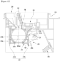
- the first portion 212 may have different heat transfer in a direction along the outer circumferential surface of the ice making cell 320a to reduce transfer of heat, which is transferred from the transparent ice heater 430 to the second tray assembly 211, to the ice making cell 320a defined by the first tray assembly 201.
- the transparent ice heater 430 may be disposed to heat both sides with respect to the lowermost end of the first portion 212.
- the first portion 212 may include a first region 214a and a second region 214b.
- the first region 214a and the second region 214b are divided by a dashed-dotted line that extends in the horizontal direction.
- the second region 214b may be a region defined above the first region 214a.
- the heat transfer rate of the second region 214b may be greater than that of the first region 214a.
- the first region 214a may include a portion at which the transparent ice heater 430 is disposed. That is, the first region 214a may include the transparent ice heater 430.
- the lowermost end 214a1 of the ice making cell 320a in the first region 214a may have a heat transfer rate less than that of the other portion of the first region 214a.
- a distance from the center of the ice making cell 320a to the outer circumferential surface is greater in the second region 214b than in the first region 214a.
- the second region 214b may include a portion in which the first tray assembly 201 and the second tray assembly 211 contact each other.
- the first region 214a may provide a portion of the ice making cell 320a.
- the second region 214b may provide the other portion of the ice making cell 320a.
- the second region 214b may be disposed farther from the transparent ice heater 430 than the first region 214a.
- a portion of the first region 214a may have the heat transfer degree less than that of the other part of the first region 214a to reduce transfer of heat, which is transferred from the transparent ice heater 430 to the first region 314a, to the ice making cell 320a defined by the second region 214b.
- a portion of the first region 214a may have a deformation resistance degree less than that of the other portion of the first region 214a and a restoration degree greater than that of the other portion of the first region 214a.
- a portion of the first region 214a may be thinner than the other portion of the first region 214a in the thickness direction from the center of the ice making cell 320a to the outer circumferential surface direction of the ice making cell 320a.
- the first region 214a may include a second tray case surrounding at least a portion of the second tray 380 and at least a portion of the second tray 380.
- the first region 214a may include the pressing part 382f of the second tray 380.
- the second portion 213 may include a first extension part 213a and a second extension part 323b, which are disposed at sides opposite to each other with respect to the central line C1.
- the first extension part 213a may be disposed at a left side of the center line C1 in FIG. 11
- the second extension part 213b may be disposed at a right side of the center line C1.
- the water supply part 240 may be disposed close to the first extension part 213a.
- the first tray assembly 301 may include a pair of guide slots 302, and the water supply part 240 may be disposed in a region between the pair of guide slots 302.
- the ice maker 200 according to this embodiment may be designed so that a position of the second tray 380 is different from the water supply position and the ice making position.
- the first contact surface 322c may be substantially maintained horizontally, and the second contact surface 382c may be disposed to be inclined with respect to the first contact surface 322c under the first tray 320.
- the second contact surface 382c may be in contact with at least a portion of the first contact surface 322c.
- the angle defined by the second contact surface 382c of the second tray 380 and the first contact surface 322c of the first tray 320 at the ice making position is less than that defined by the second contact surface of the second tray 380 and the first contact surface 322c of the first tray 320 at the water supply position.
- the entire first contact surface 322c may be in contact with the second contact surface 382c.
- the second contact surface 382c and the first contact surface 322c may be disposed to be substantially horizontal.
- the water supply position of the second tray 380 and the ice making position are different from each other. This is done for uniformly distributing the water to the plurality of ice making cells 320a without providing a water passage for the first tray 320 and/or the second tray 380 when the ice maker 200 includes the plurality of ice making cells 320a.
- the ice maker 200 includes the plurality of ice making cells 320a, when the water passage is provided in the first tray 320 and/or the second tray 380, the water supplied into the ice maker 200 may be distributed to the plurality of ice making cells 320a along the water passage.
- the ice sticks to each other even after the completion of the ice, and even if the ice is separated from each other, some of the plurality of ice includes ice made in a portion of the water passage.
- the ice may have a shape different from that of the ice making cell.
- the water supply part 240 may supply water to one opening of the plurality of openings 324.
- the water supplied through the one opening 324 falls to the second tray 380 after passing through the first tray 320.
- water may fall into any one second cell 381a of the plurality of second cells 381a of the second tray 380.
- the water supplied to any one second cell 361a may overflow from any one second cell 381a.
- the second contact surface 382c of the second tray 380 is spaced apart from the first contact surface 322c of the first tray 320, the water overflowed from any one second cells 381a may move to the other adjacent second cell 381c along the second contact surface 382c of the second tray 380. Therefore, the plurality of second cells 381a the second tray 380 may be filled with water.
- a portion of the water supplied may be filled in the second cell 381a, and the other portion of the water supplied may be filled in the space between the first tray 320 and the second tray 380.
- the water in the space between the first tray 320 and the second tray 380 may be uniformly distributed to the plurality of first cells 321a.
- ice made in the ice making cell 320a may also be made in a portion of the water passage.
- one or more of the cooling power of the cold air supply part 900 and the heating amount of the transparent ice heater may be abruptly changed several times or more in the portion at which the water passage is provided.
- the present invention may require the technique related to the aforementioned ice making position to make the transparent ice.
- the refrigerator may further include a second temperature sensor 700 (or ice making cell temperature sensor).
- the second temperature sensor 700 may be disposed adjacent to the first tray 320 to sense the temperature of the first tray 320, thereby indirectly determining the water temperature or the ice temperature of the ice making cell 320a.
- the second temperature sensor 700 may be exposed from the first tray 320 to the ice making cell 320a to directly detect a temperature of the ice making cell 320a.
- the temperature of the ice making cell 320a may be a temperature of water, ice, or cold air.
- the second temperature sensor 700 may be used to determine whether an amount of water supplied to the ice making cell 320a reaches a target water supply amount.
- the second temperature sensor 700 may be disposed adjacent to an upper end of the ice making cell 320a.
- the upper end of the ice making cell 320a may be a portion in which the opening 324 of the first tray 320 is formed.
- the lowermost end of the second temperature sensor 700 may be disposed lower than the upper end of the ice making cell 320a.
- the uppermost end of the supplied water may be lower than the upper end of the ice making cell 320a.
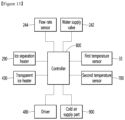
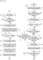
- FIG. 13 is a control block diagram of the refrigerator according to an embodiment.
- the refrigerator may include a cooler supplying a cold air to the freezing compartment 32 (or the ice making cell).
- the cooler may include at least one of a cold air supply part including at least evaporator or a thermoelectric element so as to be defined as a unit for cooling the storage chamber.
- the cooler includes a cold air supply part 900.
- the cold air supply part 900 may supply cold air, which is an example of the cold, to the freezing compartment 32 using a refrigerant cycle.
- the cold air supply part 900 may include a compressor compressing the refrigerant.
- a temperature of the cold air supplied to the freezing compartment 32 may vary according to the output (or frequency) of the compressor.
- the cold air supply part 900 may include a fan blowing air to the evaporator.
- An amount of cold air supplied to the freezing compartment 32 may vary according to the output (or rotation rate) of the fan.
- the cold air supply part 900 may include a refrigerant valve (expansion valve) controlling an amount of refrigerant flowing through the refrigerant cycle.
- An amount of refrigerant flowing through the refrigerant cycle may vary by adjusting an opening degree by the refrigerant valve, and thus, the temperature of the cold air supplied to the freezing compartment 32 may vary.
- the cold air supply part 900 may include one or more of the compressor, the fan, and the refrigerant valve.
- the cold air supply part 900 may further include the evaporator exchanging heat between the refrigerant and the air.
- the cold air heat-exchanged with the evaporator may be supplied to the ice maker 200.
- the refrigerator according to this embodiment may further include a controller 800 that controls the cold air supply part 900. Also, the refrigerator may further include a flow sensor 244 for detecting an amount of water supplied through the water supply part 240 and a water supply valve 242 controlling an amount of water.
- the flow sensor 244 may include an impeller equipped with a magnet, a hall sensor detecting magnetism during rotation of the impeller, and a housing in which the impeller is accommodated.
- a first signal may be output from the hall sensor.
- a second signal is output from the hall sensor.
- the first signal (pulse) is repetitively output, it is possible to confirm the water supply amount by counting the number of first signals. Hereinafter, a comparison of the number of pulses of the first signal to the reference number will be described.
- the controller 800 may control the water supply valve 242 using the counted number of first signals.
- the controller 800 may control a portion or all of the ice separation heater 290, the transparent ice heater 430, the driver 480, the cold air supply part 900, and the water supply valve 242.
- an output of the ice separation heater 290 and an output of the transparent ice heater 430 may be different from each other.
- an output terminal of the ice separation heater 290 and an output terminal of the transparent ice heater 430 may be provided in different shapes, incorrect connection of the two output terminals may be prevented.
- the output of the ice separation heater 290 may be set larger than that of the transparent ice heater 430. Accordingly, ice may be quickly separated from the first tray 320 by the ice separation heater 290.
- the transparent ice heater 430 may be disposed at a position adjacent to the second tray 380 described above or be disposed at a position adjacent to the first tray 320.
- the refrigerator may further include a first temperature sensor 33 that detects a temperature of the freezing compartment 32.
- the controller 800 may control the cold air supply part 900 based on the temperature sensed by the first temperature sensor 33.
- the controller 800 may determine whether ice making is completed based on the temperature sensed by the second temperature sensor 700.
- controller 800 may determine whether the water supply amount reaches the target water supply amount based on the temperature detected by the second temperature sensor 700.
- the second temperature sensor 700 may be in contact with water.
- the temperature of the water supplied to the ice making cell 320a is a temperature that is above zero and may be room temperature or slightly lower than room temperature.
- the temperature detected by the second temperature sensor 700 may be higher than the reference temperature, which is the temperature that is above zero.
- the cold air is disposed in a region corresponding to an insufficient water supply amount in the ice making cell 320a. Since the temperature of the cold air is sub-zero, the temperature detected by the second temperature sensor 700 in contact with the cold air will be lower than the reference temperature.
- the second temperature sensor 700 may be referred to as a water supply amount detection part for detecting the water supply amount.
- the water supply amount detection part may be, for example, a capacitive sensor.
- a signal (first signal) output from the water supply amount detection part when the water supply amount detection part is in contact with water, and a signal (second signal) output from the water supply amount detection part when the water supply amount detection part is not in contact with water are different from each other.
- the controller may determine that the water supply amount of the ice making cell reaches the target water supply amount.
- the water supply amount detection part In order that the water supply amount detection part is in contact with water, the water supply amount detection part may be exposed to the ice making cell. An end of the water supply amount detection part, which is in contact with water, may be disposed lower than the upper end of the ice making cell.
- FIG. 16 is a view for explaining a height reference depending on a relative position of the transparent heater with respect to the ice making cell
- FIG. 17 is a view for explaining an output of the transparent heater per unit height of water within the ice making cell.
- a direction in which the second tray 380 moves from the ice making position of FIG. 19 to the ice separation position of FIG. 22 may be referred to as forward movement (or forward rotation).
- the direction from the ice separation position of FIG. 22 to the water supply position of FIG. 18 may be referred to as reverse movement (or reverse rotation).
- the movement to the water supply position of the second tray 380 is detected by a sensor (not shown), and when it is detected that the second tray 380 moves to the water supply position, the controller 800 stops the driver 480.
- the controller 800 may determine whether the temperature detected by the second temperature sensor 700 reaches a temperature below the water supply start temperature (S2).
- the ice separation heater 290 and/or the ice making heater 430 operate to separate ice.
- Heat from the ice separation heater 290 and/or the ice making heater 430 is provided to the ice making cell 320a.
- the temperature detected by the second temperature sensor 700 may increase to a temperature higher than a temperature that is above zero due to the heat provided to the ice making cell 320a.
- the temperature detected by the second temperature sensor 700 reaches a water supply start temperature by an effect of heat of the heater even though water as much as the target water supply amount has not been supplied to the ice making cell 320a.
- the completion of the ice making may be determined in a state in which the ice is not completely frozen, and the ice does not become transparent.
- the water supply does not start immediately after the ice separation is completed, but stands by so that the temperature detected by the second temperature sensor 700 decreases due to the cold air.
- the water supply may start.
- the water supply may start when a set standby time elapses after the ice separation is completed.
- the set standby time may be set to a time so that the temperature detected by the second temperature sensor 700 is sufficiently lowered by the cold air.
- the water supply start temperature may be a temperature lower than the reference temperature.
- the water supply start temperature may be a sub-zero temperature.
- the controller 800 starts the first water supply (S3). That is, the controller 800 turns on the water supply valve 242 to supply water to the ice making cell 320a.
- a gap exists between the impeller and an inner circumferential surface of the housing.
- the impeller rotates, a portion of water flows by the impeller, and the other portion is bypassed to flow through the gap between the impeller and the inner circumferential surface of the housing.
- the actual water supply amount is greater than the target water supply amount.
- the actual water supply amount is greater than the target water supply amount, since water is filled up to a position higher than the opening 324 of the ice making cell 320a, ice is generated up to the auxiliary storage chamber 325 or protrudes outside the auxiliary storage chamber 325 during the ice making process.
- the number of pulses output in the rotation process of the impeller reaches the reference number corresponding to the target water supply amount because a flow rate itself is small in the passage through which water flows. Even when the valve 242 is turned off, the actual water supply amount is significantly smaller than the target water supply amount.
- the passage may not be completely filled with water, and air may be contained.
- the actual water supply amount may be smaller than the target water supply amount. If the ice making starts immediately in this state, it may be determined that the ice making is completed in a state in which ice is not completely frozen, and the ice may not become transparent.
- the water pressure is different for each area on which the refrigerator is installed, and in consideration of the structural characteristics of the flow sensor, the water supply is performed at least twice or more so that the water supply amount is the same as or almost similar to the target water supply amount.
- the first water supply it is possible to control the water supply as much as the standard water supply amount less than the target water supply amount.
- the water supply starts, and the controller 800 determines whether a reference time elapses (S4), and when the reference time elapses, the water supply pressure may be determined (or detected). The controller 800 may determine whether the detected water pressure is less than the reference water pressure (S5).
- the number of pulses output during the rotation of the impeller after the reference time elapses may vary.
- the number of pulses when the water pressure is low is smaller than the number of pulses when the water pressure is high.
- the controller 800 may determine whether the detected water pressure is less than the reference water pressure based on the number of pulses.
- the water supply amount (reference water supply amount) after the completion of the first water supply may be set differently.
- the water supply amount after the completion of the first water supply is less than the water supply amount when the water pressure is high.
- the reference water supply amount when the water supply water pressure is low may be set to be larger than the reference water supply amount when the water supply water pressure is high.
- the controller 800 sets the reference water supply amount as the first reference water supply amount.
- the controller 800 sets the reference water supply amount as the second reference water supply amount. The second reference water supply amount is greater than the first reference water supply amount.
- the controller 800 turns off the water supply valve 242 to stop the water supply (S8).
- the controller 800 turns off the water supply valve 242 to stop the water supply (S8).
- the controller 800 controls the driver 480 to allow the second tray 380 to move to the ice making position (S9).
- the driver 480 may be controlled so that the second tray 380 moves to the ice making position after standing by for a standby time until water is distributed to the plurality of ice making cells 320a.
- the controller 800 may control the driver 480 to allow the second tray 380 to move from the water supply position in the reverse direction.
- the second contact surface 382c of the second tray 380 comes close to the first contact surface 322c of the first tray 320.
- water between the second contact surface 382c of the second tray 380 and the first contact surface 322c of the first tray 320 is divided into each of the plurality of second cells 381a and then is distributed.
- the controller 800 may control the driver 480 to allow the second tray 380 to move from the water supply position in the reverse direction.
- the movement to the ice making position of the second tray 380 is detected by a sensor, and when it is detected that the second tray 380 moves to the ice making position, the controller 800 stops the driver 480.
- the controller 800 may determine whether the actual water supply amount of the ice making cell 320a reaches a target water supply amount (S10). For example, after moving to the ice making position, it may be determined whether the temperature detected by the second temperature sensor 700 reaches a reference temperature within a set time.
- S10 target water supply amount
- the controller 800 may perform additional water supply.
- controller 800 may control the driver 480 so that the second tray 380 moves again to the water supply position (S11).
- the controller 800 may determine whether the temperature detected by the second temperature sensor 700 reaches a water supply start temperature (S12).
- the water supply amount does not reach the target water supply amount, it is determined that the temperature detected by the second temperature sensor 700 reaches the reference temperature due to the increase in temperature of the freezing compartment 32, so that it is erroneously determined that the water supply amount reaches the target water supply amount.
- the water supply valve 242 may be controlled so that the water supply is performed by the additional water supply amount (S13).
- the additional water supply amount is less than the reference water supply amount.
- the controller 800 turns on the water supply valve 242 for water supply, and when the number of pulses output from the flow sensor 244 reaches an additional water supply reference number corresponding to the additional water supply amount, the water supply valve 242 is turned off.
- the additional water supply amount may be set to be larger than the additional water supply amount when the detected water pressure is higher than the reference water pressure.
- the additional water supply amount when the detected water pressure is less than the reference water pressure is set to be larger than the additional water supply amount, if the detected water pressure is higher than the reference water pressure, it is possible to minimize an increase in number of times of the additional water supply when the detected water pressure is low. As described above, if the increase in number of times of the additional water supply is minimized, water may be prevented from being phase-changed into ice during the water supply process.
- the controller 800 may determine whether the water supply amount of the ice making cell 320a reaches a target water supply amount (S15).
- the controller 800 performs the additional water supply again.
- the additional water supply may be repetitively performed until the water supply amount to the ice making cell reaches the target water supply amount.
- the first water supply process may be used as a basic water supply process.
- this embodiment may include a basic water supply process and one or more additional water supply processes.
- the reference water supply amount may be set to 80% or more of the target water supply amount.
- the additional water supply amount may be set to less than 20% of the target water supply amount. While the number of additional water supply decreases as the amount of additional water supply increases, there is a high possibility that the actual water supply amount exceeds the target water supply amount after the additional water supply.
- the controller 800 may control the cold air supply part 900 to supply cold air to the ice making cell 320a.
- the controller 800 may control the transparent ice heater 430 to be turned on in at least partial sections of the cold air supply part 900 supplying the cold air to the ice making cell 320a.
- the controller 800 may determine whether the turn-on condition of the transparent ice heater 430 is satisfied (S17).
- the water supplied to the ice making cell 320a may be water having normal temperature or water having a temperature lower than the normal temperature.
- the temperature of the water supplied is higher than a freezing point of water.
- the temperature of the water is lowered by the cold air, and when the temperature of the water reaches the freezing point of the water, the water is changed into ice.
- the transparent ice heater 430 may not be turned on until the water is phase-changed into ice.
- the transparency of the ice may vary depending on the presence of the air bubbles in the portion at which ice is made after the ice making is started. If heat is supplied to the ice making cell 320a before the ice is made, the transparent ice heater 430 may operate regardless of the transparency of the ice.
- the transparent ice heater 430 is turned on immediately after the start of ice making, since the transparency is not affected, it is also possible to turn on the transparent ice heater 430 after the start of the ice making.
- the controller 800 determines that the turn-on condition of the transparent ice heater 430 is satisfied when a temperature detected by the second temperature sensor 700 reaches a turn-on reference temperature.
- the turn-on reference temperature may be a temperature for determining that water starts to freeze at the uppermost side (opening-side) of the ice making cell 320a.
- the temperature of the ice in the ice making cell 320a is below zero.
- the temperature of the first tray 320 may be higher than the temperature of the ice in the ice making cell 320a.
- the temperature detected by the second temperature sensor 700 may be below zero.
- the turn-on reference temperature may be set to the below-zero temperature.
- the ice temperature of the ice making cell 320a is below zero, i.e., lower than the below reference temperature. Therefore, it may be indirectly determined that ice is made in the ice making cell 320a.
- the transparent ice heater 430 when the transparent ice heater 430 is not used, the heat of the transparent ice heater 430 is transferred into the ice making cell 320a.
- the transparent ice heater 430 when the second tray 380 is disposed below the first tray 320, the transparent ice heater 430 is disposed to supply the heat to the second tray 380, the ice may be made from an upper side of the ice making cell 320a.
- water or bubbles may be convex in the ice making cell 320a, and the bubbles may move to the transparent ice heater 430.
- the mass (or volume) per unit height of water in the ice making cell 320a may be the same or different according to the shape of the ice making cell 320a.
- the mass (or volume) per unit height of water in the ice making cell 320a is the same.
- the mass (or volume) per unit height of water is different.
- the ice making rate is high, whereas if the mass per unit height of water is high, the ice making rate is slow.
- the ice making rate per unit height of water is not constant, and thus, the transparency of the ice may vary according to the unit height.
- the bubbles may not move from the ice to the water, and the ice may contain the bubbles to lower the transparency.
- the controller 800 may control the cooling power and/or the heating amount so that the cooling power of the cold air supply part 900 and/or the heating amount of the transparent ice heater 430 is variable according to the mass per unit height of the water of the ice making cell 320a (S19).
- variable of the cooling power of the cold air supply part 900 may include one or more of a variable output of the compressor, a variable output of the fan, and a variable opening degree of the refrigerant valve.
- the variation in the heating amount of the transparent ice heater 430 may represent varying the output of the transparent ice heater 430 or varying the duty of the transparent ice heater 430.
- the duty of the transparent ice heater 430 represents a ratio of the turn-on time and the turn-off time of the transparent ice heater 430 in one cycle, or a ratio of the turn-on time and the turn-off time of the transparent ice heater 430 in one cycle.
- a reference of the unit height of water in the ice making cell 320a may vary according to a relative position of the ice making cell 320a and the transparent ice heater 430.
- the transparent ice heater 430 at the bottom surface of the ice making cell 320a may be disposed to have the same height.
- a line connecting the transparent ice heater 430 is a horizontal line, and a line extending in a direction perpendicular to the horizontal line serves as a reference for the unit height of the water of the ice making cell 320a.
- ice is made from the uppermost side of the ice making cell 320a and then is grown.
- the transparent ice heater 430 at the bottom surface of the ice making cell 320a may be disposed to have different heights.
- ice may be made at a position spaced apart from the uppermost end to the left side of the ice making cell 320a, and the ice may be grown to a right lower side at which the transparent ice heater 430 is disposed.
- a line (reference line) perpendicular to the line connecting two points of the transparent ice heater 430 serves as a reference for the unit height of water of the ice making cell 320a.
- the reference line of FIG. 16(b) is inclined at a predetermined angle from the vertical line.
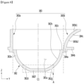
- FIG. 17 illustrates a unit height division of water and an output amount of transparent ice heater per unit height when the transparent ice heater is disposed as shown in FIG. 16(a) .
- the mass per unit height of water in the ice making cell 320a increases from the upper side to the lower side to reach the maximum and then decreases again.
- the water (or the ice making cell itself) in the spherical ice making cell 320a having a diameter of about 50 mm is divided into nine sections (section A to section I) by 6 mm height (unit height).
- section A to section I the spherical ice making cell 320a having a diameter of about 50 mm
- unit height 6 mm height
- the height of each section to be divided is equal to the section A to the section H, and the section I is lower than the remaining sections.
- the unit heights of all divided sections may be the same depending on the diameter of the ice making cell 320a and the number of divided sections,
- the section E is a section in which the mass of unit height of water is maximum.
- a diameter of the ice making cell 320a, a horizontal cross-sectional area of the ice making cell 320a, or a circumference of the ice may be maximum.
- the ice making rate in section E is the lowest, the ice making rate in the sections A and I is the fastest.
- the transparency of the ice may vary for the height.
- the ice making rate may be too fast to contain bubbles, thereby lowering the transparency.
- the output of the transparent ice heater 430 may be controlled so that the ice making rate for each unit height is the same or similar while the bubbles move from the portion at which ice is made to the water in the ice making process.
- the output W5 of the transparent ice heater 430 in the section E may be set to a minimum value. Since the volume of the section D is less than that of the section E, the volume of the ice may be reduced as the volume decreases, and thus it is necessary to delay the ice making rate. Thus, an output W6 of the transparent ice heater 430 in the section D may be set to a value greater than an output W5 of the transparent ice heater 430 in the section E.
- an output W3 of the transparent ice heater 430 in the section C may be set to a value greater than the output W4 of the transparent ice heater 430 in the section D.
- an output W2 of the transparent ice heater 430 in the section B may be set to a value greater than the output W3 of the transparent ice heater 430 in the section C.
- an output W 1 of the transparent ice heater 430 in the section A may be set to a value greater than the output W2 of the transparent ice heater 430 in the section B.
- the output of the transparent ice heater 430 may increase as the lower side in the section E (see W6, W7, W8, and W9).
- the output of the transparent ice heater 430 is gradually reduced from the first section to the intermediate section after the transparent ice heater 430 is initially turned on.
- the output of the transparent ice heater 430 in two adjacent sections may be set to be the same according to the type or mass of the made ice.
- the output of section C and section D may be the same. That is, the output of the transparent ice heater 430 may be the same in at least two sections.
- the cooling power of the cold air supply part 900 may be maximum in the intermediate section in which the mass for each unit height of water is minimum.
- the cooling power of the cold air supply part 900 may be gradually reduced again from the next section of the intermediate section.
Landscapes
- Engineering & Computer Science (AREA)
- Physics & Mathematics (AREA)
- Mechanical Engineering (AREA)
- Thermal Sciences (AREA)
- General Engineering & Computer Science (AREA)
- Production, Working, Storing, Or Distribution Of Ice (AREA)
- Cold Air Circulating Systems And Constructional Details In Refrigerators (AREA)
Applications Claiming Priority (8)
| Application Number | Priority Date | Filing Date | Title |
|---|---|---|---|
| KR1020180117785A KR102669631B1 (ko) | 2018-10-02 | 2018-10-02 | 제빙기 및 이를 포함하는 냉장고 |
| KR1020180117819A KR102709377B1 (ko) | 2018-10-02 | 2018-10-02 | 제빙기 및 이를 포함하는 냉장고 |
| KR1020180117822A KR102731115B1 (ko) | 2018-10-02 | 2018-10-02 | 제빙기 및 이를 포함하는 냉장고 |
| KR1020180117821A KR102636442B1 (ko) | 2018-10-02 | 2018-10-02 | 제빙기 및 이를 포함하는 냉장고 |
| KR1020180142117A KR102657068B1 (ko) | 2018-11-16 | 2018-11-16 | 아이스 메이커의 제어방법 |
| KR1020190111420A KR102861715B1 (ko) | 2019-09-09 | 2019-09-09 | 냉장고 |
| PCT/KR2019/012886 WO2020071773A1 (ko) | 2018-10-02 | 2019-10-01 | 냉장고 |
| EP19868712.1A EP3862692B1 (de) | 2018-10-02 | 2019-10-01 | Kühlschrank |
Related Parent Applications (2)
| Application Number | Title | Priority Date | Filing Date |
|---|---|---|---|
| EP19868712.1A Division EP3862692B1 (de) | 2018-10-02 | 2019-10-01 | Kühlschrank |
| EP19868712.1A Division-Into EP3862692B1 (de) | 2018-10-02 | 2019-10-01 | Kühlschrank |
Publications (2)
| Publication Number | Publication Date |
|---|---|
| EP4575358A2 true EP4575358A2 (de) | 2025-06-25 |
| EP4575358A3 EP4575358A3 (de) | 2025-08-27 |
Family
ID=70055959
Family Applications (2)
| Application Number | Title | Priority Date | Filing Date |
|---|---|---|---|
| EP19868712.1A Active EP3862692B1 (de) | 2018-10-02 | 2019-10-01 | Kühlschrank |
| EP25175062.6A Pending EP4575358A3 (de) | 2018-10-02 | 2019-10-01 | Kühlschrank |
Family Applications Before (1)
| Application Number | Title | Priority Date | Filing Date |
|---|---|---|---|
| EP19868712.1A Active EP3862692B1 (de) | 2018-10-02 | 2019-10-01 | Kühlschrank |
Country Status (4)
| Country | Link |
|---|---|
| US (2) | US12158296B2 (de) |
| EP (2) | EP3862692B1 (de) |
| CN (1) | CN112789466A (de) |
| WO (1) | WO2020071773A1 (de) |
Families Citing this family (1)
| Publication number | Priority date | Publication date | Assignee | Title |
|---|---|---|---|---|
| KR20240120568A (ko) * | 2023-01-31 | 2024-08-07 | 삼성전자주식회사 | 냉장고 |
Citations (2)
| Publication number | Priority date | Publication date | Assignee | Title |
|---|---|---|---|---|
| JPH09269172A (ja) | 1996-03-29 | 1997-10-14 | Toshiba Corp | 製氷装置 |
| KR101850918B1 (ko) | 2011-10-04 | 2018-05-30 | 엘지전자 주식회사 | 아이스 메이커 및 이를 이용한 얼음 제조 방법 |
Family Cites Families (43)
| Publication number | Priority date | Publication date | Assignee | Title |
|---|---|---|---|---|
| JPS6070543U (ja) | 1983-10-19 | 1985-05-18 | 日本電気株式会社 | 二枚重ねパツキン |
| JPH01230969A (ja) | 1988-03-09 | 1989-09-14 | Hoshizaki Electric Co Ltd | 自動製氷機の製氷構造 |
| JPH05203299A (ja) * | 1992-01-23 | 1993-08-10 | Matsushita Refrig Co Ltd | 自動製氷装置 |
| JPH05203302A (ja) | 1992-01-30 | 1993-08-10 | Matsushita Refrig Co Ltd | 自動製氷装置 |
| JPH0670543A (ja) | 1992-08-19 | 1994-03-11 | Shindengen Electric Mfg Co Ltd | 直列共振コンバータ |
| KR100301636B1 (ko) | 1998-12-28 | 2001-11-22 | 전주범 | 냉장고자동제빙기의급수제어방법 |
| JP2001289544A (ja) | 2001-02-13 | 2001-10-19 | Sanyo Electric Co Ltd | 製氷装置及びそれを備えた冷凍冷蔵庫 |
| JP2003114072A (ja) | 2001-10-03 | 2003-04-18 | Sanyo Electric Co Ltd | 製氷装置及びこの装置を備えた冷凍冷蔵庫 |
| JP2002350019A (ja) | 2002-04-10 | 2002-12-04 | Matsushita Refrig Co Ltd | 透明氷の製造方法 |
| US6935124B2 (en) * | 2002-05-30 | 2005-08-30 | Matsushita Electric Industrial Co., Ltd. | Clear ice making apparatus, clear ice making method and refrigerator |
| US7100379B2 (en) * | 2003-08-14 | 2006-09-05 | Samsung Electronics Co., Ltd. | Water supply control apparatus and method for ice maker |
| KR100607640B1 (ko) | 2003-10-30 | 2006-08-02 | (주) 엘플러스닷컴 | 급속 제빙장치 |
| KR20050069319A (ko) | 2003-12-31 | 2005-07-05 | 삼성전자주식회사 | 냉장고용 자동 제빙장치 |
| KR20050096336A (ko) | 2004-03-30 | 2005-10-06 | 삼성전자주식회사 | 냉장고 및 그 제어방법 |
| JP4657626B2 (ja) | 2004-05-12 | 2011-03-23 | 日本電産サーボ株式会社 | 自動製氷装置 |
| KR100642362B1 (ko) * | 2004-11-02 | 2006-11-03 | 엘지전자 주식회사 | 제빙기의 급수량 제어장치 및 제어방법 |
| WO2008004763A1 (en) | 2006-07-01 | 2008-01-10 | Lg Electronics, Inc. | Supercooling apparatus |
| KR20090012680A (ko) | 2007-07-31 | 2009-02-04 | 엘지전자 주식회사 | 냉장고용 제빙기의 정량 급수장치 및 급수방법 |
| KR101405959B1 (ko) | 2008-01-17 | 2014-06-12 | 엘지전자 주식회사 | 제빙장치 및 이를 포함하는 냉장고 |
| KR101559775B1 (ko) | 2008-11-14 | 2015-10-13 | 엘지전자 주식회사 | 제빙장치 및 그 제어방법 |
| KR101622595B1 (ko) * | 2008-11-19 | 2016-05-19 | 엘지전자 주식회사 | 제빙장치 및 이를 구비한 냉장고 및 이 냉장고의 제빙방법 |
| KR101688133B1 (ko) * | 2009-06-22 | 2016-12-20 | 엘지전자 주식회사 | 제빙장치 및 이를 구비한 냉장고 및 이 냉장고의 제빙방법 |
| JP4680311B2 (ja) | 2009-09-16 | 2011-05-11 | シャープ株式会社 | 冷凍冷蔵庫の製氷装置 |
| JP2011064371A (ja) | 2009-09-16 | 2011-03-31 | Sharp Corp | 冷凍冷蔵庫の製氷装置 |
| KR101643635B1 (ko) | 2009-10-07 | 2016-07-29 | 엘지전자 주식회사 | 제빙장치 및 이를 이용한 제빙방법 |
| JP2011237077A (ja) | 2010-05-07 | 2011-11-24 | Toshiba Corp | 自動製氷装置 |
| KR20110135124A (ko) * | 2010-06-10 | 2011-12-16 | 엘지전자 주식회사 | 아이스 메이커 및 아이스 메이커가 구비된 냉장고 |
| KR101658674B1 (ko) | 2010-07-02 | 2016-09-21 | 엘지전자 주식회사 | 얼음 저장 장치 및 그 제어 방법 |
| KR20140025398A (ko) | 2011-04-22 | 2014-03-04 | 우베 고산 가부시키가이샤 | 비수 전해액, 그것을 이용한 축전 디바이스, 및 트라이플루오로메틸벤젠 화합물 |
| KR101890939B1 (ko) | 2011-07-15 | 2018-08-23 | 엘지전자 주식회사 | 아이스 메이커 |
| KR101968563B1 (ko) | 2011-07-15 | 2019-08-20 | 엘지전자 주식회사 | 아이스 메이커 |
| KR101932076B1 (ko) | 2012-06-12 | 2018-12-24 | 엘지전자 주식회사 | 냉장고 |
| KR102023412B1 (ko) * | 2012-06-12 | 2019-09-20 | 엘지전자 주식회사 | 냉장고 |
| US9696079B2 (en) * | 2012-12-13 | 2017-07-04 | Whirlpool Corporation | Rotational ice maker |
| KR102130632B1 (ko) | 2013-01-02 | 2020-07-06 | 엘지전자 주식회사 | 아이스 메이커 |
| KR101981680B1 (ko) | 2013-10-16 | 2019-05-23 | 삼성전자주식회사 | 제빙 트레이 및 이를 갖는 냉장고 |
| EP3680586B1 (de) * | 2014-02-24 | 2022-11-30 | LG Electronics Inc. | Kühlschrank mit der eisherstellungsvorrichtung |
| KR101652585B1 (ko) | 2014-10-21 | 2016-08-30 | 엘지전자 주식회사 | 냉장고의 제어 방법 |
| KR102331090B1 (ko) * | 2015-02-27 | 2021-11-25 | 삼성전자주식회사 | 냉장고 |
| KR20180080021A (ko) | 2017-01-03 | 2018-07-11 | 삼성전자주식회사 | 제빙장치, 이를 구비한 냉장고 및 제빙방법 |
| KR102758884B1 (ko) | 2017-02-14 | 2025-01-24 | 삼성전자주식회사 | 냉장고 및 그 제어 방법 |
| KR20180100752A (ko) | 2017-03-02 | 2018-09-12 | 주식회사 대창 | 히팅모듈 및 이를 포함하는 제빙기, 비데, 정수기, 냉장고 |
| US10697684B2 (en) * | 2018-03-20 | 2020-06-30 | Bsh Home Appliances Corporation | Automatic ice-sphere-making system for refrigerator appliance |
-
2019
- 2019-10-01 US US17/282,310 patent/US12158296B2/en active Active
- 2019-10-01 EP EP19868712.1A patent/EP3862692B1/de active Active
- 2019-10-01 CN CN201980064193.8A patent/CN112789466A/zh active Pending
- 2019-10-01 EP EP25175062.6A patent/EP4575358A3/de active Pending
- 2019-10-01 WO PCT/KR2019/012886 patent/WO2020071773A1/ko not_active Ceased
-
2024
- 2024-10-21 US US18/921,828 patent/US20250044010A1/en active Pending
Patent Citations (2)
| Publication number | Priority date | Publication date | Assignee | Title |
|---|---|---|---|---|
| JPH09269172A (ja) | 1996-03-29 | 1997-10-14 | Toshiba Corp | 製氷装置 |
| KR101850918B1 (ko) | 2011-10-04 | 2018-05-30 | 엘지전자 주식회사 | 아이스 메이커 및 이를 이용한 얼음 제조 방법 |
Also Published As
| Publication number | Publication date |
|---|---|
| CN112789466A (zh) | 2021-05-11 |
| US20210341205A1 (en) | 2021-11-04 |
| WO2020071773A1 (ko) | 2020-04-09 |
| US20250044010A1 (en) | 2025-02-06 |
| US12158296B2 (en) | 2024-12-03 |
| EP4575358A3 (de) | 2025-08-27 |
| EP3862692A1 (de) | 2021-08-11 |
| EP3862692A4 (de) | 2022-07-27 |
| EP3862692B1 (de) | 2025-12-17 |
Similar Documents
| Publication | Publication Date | Title |
|---|---|---|
| US20240295354A1 (en) | Refrigerator | |
| KR102861715B1 (ko) | 냉장고 | |
| US20240337425A1 (en) | Refrigerator and control method therefor | |
| EP3862693B1 (de) | Kühlschrank | |
| US20250052470A1 (en) | Refrigerator | |
| AU2023210670A1 (en) | Refrigerator and method for controlling the same | |
| US20240210086A1 (en) | Refrigerator | |
| EP3862707B1 (de) | Kühlschrank und verfahren zur steuerung davon | |
| US20250044010A1 (en) | Refrigerator | |
| EP3862694B1 (de) | Kühlschrank | |
| EP3862672A1 (de) | Kühlschrank und verfahren zur steuerung davon | |
| EP3862667B1 (de) | Kühlschrank und steuerungsverfahren dafür |
Legal Events
| Date | Code | Title | Description |
|---|---|---|---|
| PUAI | Public reference made under article 153(3) epc to a published international application that has entered the european phase |
Free format text: ORIGINAL CODE: 0009012 |
|
| STAA | Information on the status of an ep patent application or granted ep patent |
Free format text: STATUS: THE APPLICATION HAS BEEN PUBLISHED |
|
| AC | Divisional application: reference to earlier application |
Ref document number: 3862692 Country of ref document: EP Kind code of ref document: P |
|
| AK | Designated contracting states |
Kind code of ref document: A2 Designated state(s): AL AT BE BG CH CY CZ DE DK EE ES FI FR GB GR HR HU IE IS IT LI LT LU LV MC MK MT NL NO PL PT RO RS SE SI SK SM TR |
|
| REG | Reference to a national code |
Ref country code: DE Ref legal event code: R079 Free format text: PREVIOUS MAIN CLASS: F25C0005020000 Ipc: F25D0011000000 |
|
| PUAL | Search report despatched |
Free format text: ORIGINAL CODE: 0009013 |
|
| AK | Designated contracting states |
Kind code of ref document: A3 Designated state(s): AL AT BE BG CH CY CZ DE DK EE ES FI FR GB GR HR HU IE IS IT LI LT LU LV MC MK MT NL NO PL PT RO RS SE SI SK SM TR |
|
| RIC1 | Information provided on ipc code assigned before grant |
Ipc: F25D 11/00 20060101AFI20250722BHEP Ipc: F25D 29/00 20060101ALI20250722BHEP Ipc: F25D 25/02 20060101ALI20250722BHEP Ipc: F25C 1/24 20180101ALI20250722BHEP Ipc: F25C 5/02 20060101ALI20250722BHEP Ipc: F25C 5/18 20180101ALI20250722BHEP Ipc: F25C 5/04 20060101ALI20250722BHEP Ipc: F25C 1/18 20060101ALN20250722BHEP |
|
| STAA | Information on the status of an ep patent application or granted ep patent |
Free format text: STATUS: REQUEST FOR EXAMINATION WAS MADE |
|
| 17P | Request for examination filed |
Effective date: 20260211 |