EP4574591A1 - Procédé et dispositif pour effectuer un freinage dans un véhicule autonome - Google Patents
Procédé et dispositif pour effectuer un freinage dans un véhicule autonome Download PDFInfo
- Publication number
- EP4574591A1 EP4574591A1 EP24200546.0A EP24200546A EP4574591A1 EP 4574591 A1 EP4574591 A1 EP 4574591A1 EP 24200546 A EP24200546 A EP 24200546A EP 4574591 A1 EP4574591 A1 EP 4574591A1
- Authority
- EP
- European Patent Office
- Prior art keywords
- vehicle
- data
- braking
- opponent
- ego
- Prior art date
- Legal status (The legal status is an assumption and is not a legal conclusion. Google has not performed a legal analysis and makes no representation as to the accuracy of the status listed.)
- Pending
Links
Images

Classifications
-
- B—PERFORMING OPERATIONS; TRANSPORTING
- B60—VEHICLES IN GENERAL
- B60T—VEHICLE BRAKE CONTROL SYSTEMS OR PARTS THEREOF; BRAKE CONTROL SYSTEMS OR PARTS THEREOF, IN GENERAL; ARRANGEMENT OF BRAKING ELEMENTS ON VEHICLES IN GENERAL; PORTABLE DEVICES FOR PREVENTING UNWANTED MOVEMENT OF VEHICLES; VEHICLE MODIFICATIONS TO FACILITATE COOLING OF BRAKES
- B60T7/00—Brake-action initiating means
- B60T7/12—Brake-action initiating means for automatic initiation; for initiation not subject to will of driver or passenger
-
- B—PERFORMING OPERATIONS; TRANSPORTING
- B60—VEHICLES IN GENERAL
- B60W—CONJOINT CONTROL OF VEHICLE SUB-UNITS OF DIFFERENT TYPE OR DIFFERENT FUNCTION; CONTROL SYSTEMS SPECIALLY ADAPTED FOR HYBRID VEHICLES; ROAD VEHICLE DRIVE CONTROL SYSTEMS FOR PURPOSES NOT RELATED TO THE CONTROL OF A PARTICULAR SUB-UNIT
- B60W30/00—Purposes of road vehicle drive control systems not related to the control of a particular sub-unit, e.g. of systems using conjoint control of vehicle sub-units
- B60W30/08—Active safety systems predicting or avoiding probable or impending collision or attempting to minimise its consequences
- B60W30/09—Taking automatic action to avoid collision, e.g. braking and steering
-
- B—PERFORMING OPERATIONS; TRANSPORTING
- B60—VEHICLES IN GENERAL
- B60T—VEHICLE BRAKE CONTROL SYSTEMS OR PARTS THEREOF; BRAKE CONTROL SYSTEMS OR PARTS THEREOF, IN GENERAL; ARRANGEMENT OF BRAKING ELEMENTS ON VEHICLES IN GENERAL; PORTABLE DEVICES FOR PREVENTING UNWANTED MOVEMENT OF VEHICLES; VEHICLE MODIFICATIONS TO FACILITATE COOLING OF BRAKES
- B60T7/00—Brake-action initiating means
- B60T7/12—Brake-action initiating means for automatic initiation; for initiation not subject to will of driver or passenger
- B60T7/16—Brake-action initiating means for automatic initiation; for initiation not subject to will of driver or passenger operated by remote control, i.e. initiating means not mounted on vehicle
- B60T7/18—Brake-action initiating means for automatic initiation; for initiation not subject to will of driver or passenger operated by remote control, i.e. initiating means not mounted on vehicle operated by wayside apparatus
-
- B—PERFORMING OPERATIONS; TRANSPORTING
- B60—VEHICLES IN GENERAL
- B60T—VEHICLE BRAKE CONTROL SYSTEMS OR PARTS THEREOF; BRAKE CONTROL SYSTEMS OR PARTS THEREOF, IN GENERAL; ARRANGEMENT OF BRAKING ELEMENTS ON VEHICLES IN GENERAL; PORTABLE DEVICES FOR PREVENTING UNWANTED MOVEMENT OF VEHICLES; VEHICLE MODIFICATIONS TO FACILITATE COOLING OF BRAKES
- B60T7/00—Brake-action initiating means
- B60T7/12—Brake-action initiating means for automatic initiation; for initiation not subject to will of driver or passenger
- B60T7/22—Brake-action initiating means for automatic initiation; for initiation not subject to will of driver or passenger initiated by contact of vehicle, e.g. bumper, with an external object, e.g. another vehicle, or by means of contactless obstacle detectors mounted on the vehicle
-
- B—PERFORMING OPERATIONS; TRANSPORTING
- B60—VEHICLES IN GENERAL
- B60T—VEHICLE BRAKE CONTROL SYSTEMS OR PARTS THEREOF; BRAKE CONTROL SYSTEMS OR PARTS THEREOF, IN GENERAL; ARRANGEMENT OF BRAKING ELEMENTS ON VEHICLES IN GENERAL; PORTABLE DEVICES FOR PREVENTING UNWANTED MOVEMENT OF VEHICLES; VEHICLE MODIFICATIONS TO FACILITATE COOLING OF BRAKES
- B60T8/00—Arrangements for adjusting wheel-braking force to meet varying vehicular or ground-surface conditions, e.g. limiting or varying distribution of braking force
- B60T8/17—Using electrical or electronic regulation means to control braking
- B60T8/1755—Brake regulation specially adapted to control the stability of the vehicle, e.g. taking into account yaw rate or transverse acceleration in a curve
- B60T8/17558—Brake regulation specially adapted to control the stability of the vehicle, e.g. taking into account yaw rate or transverse acceleration in a curve specially adapted for collision avoidance or collision mitigation
-
- B—PERFORMING OPERATIONS; TRANSPORTING
- B60—VEHICLES IN GENERAL
- B60W—CONJOINT CONTROL OF VEHICLE SUB-UNITS OF DIFFERENT TYPE OR DIFFERENT FUNCTION; CONTROL SYSTEMS SPECIALLY ADAPTED FOR HYBRID VEHICLES; ROAD VEHICLE DRIVE CONTROL SYSTEMS FOR PURPOSES NOT RELATED TO THE CONTROL OF A PARTICULAR SUB-UNIT
- B60W30/00—Purposes of road vehicle drive control systems not related to the control of a particular sub-unit, e.g. of systems using conjoint control of vehicle sub-units
- B60W30/08—Active safety systems predicting or avoiding probable or impending collision or attempting to minimise its consequences
- B60W30/095—Predicting travel path or likelihood of collision
- B60W30/0953—Predicting travel path or likelihood of collision the prediction being responsive to vehicle dynamic parameters
-
- B—PERFORMING OPERATIONS; TRANSPORTING
- B60—VEHICLES IN GENERAL
- B60W—CONJOINT CONTROL OF VEHICLE SUB-UNITS OF DIFFERENT TYPE OR DIFFERENT FUNCTION; CONTROL SYSTEMS SPECIALLY ADAPTED FOR HYBRID VEHICLES; ROAD VEHICLE DRIVE CONTROL SYSTEMS FOR PURPOSES NOT RELATED TO THE CONTROL OF A PARTICULAR SUB-UNIT
- B60W30/00—Purposes of road vehicle drive control systems not related to the control of a particular sub-unit, e.g. of systems using conjoint control of vehicle sub-units
- B60W30/08—Active safety systems predicting or avoiding probable or impending collision or attempting to minimise its consequences
- B60W30/095—Predicting travel path or likelihood of collision
- B60W30/0956—Predicting travel path or likelihood of collision the prediction being responsive to traffic or environmental parameters
-
- B—PERFORMING OPERATIONS; TRANSPORTING
- B60—VEHICLES IN GENERAL
- B60T—VEHICLE BRAKE CONTROL SYSTEMS OR PARTS THEREOF; BRAKE CONTROL SYSTEMS OR PARTS THEREOF, IN GENERAL; ARRANGEMENT OF BRAKING ELEMENTS ON VEHICLES IN GENERAL; PORTABLE DEVICES FOR PREVENTING UNWANTED MOVEMENT OF VEHICLES; VEHICLE MODIFICATIONS TO FACILITATE COOLING OF BRAKES
- B60T2201/00—Particular use of vehicle brake systems; Special systems using also the brakes; Special software modules within the brake system controller
- B60T2201/02—Active or adaptive cruise control system; Distance control
- B60T2201/022—Collision avoidance systems
-
- B—PERFORMING OPERATIONS; TRANSPORTING
- B60—VEHICLES IN GENERAL
- B60T—VEHICLE BRAKE CONTROL SYSTEMS OR PARTS THEREOF; BRAKE CONTROL SYSTEMS OR PARTS THEREOF, IN GENERAL; ARRANGEMENT OF BRAKING ELEMENTS ON VEHICLES IN GENERAL; PORTABLE DEVICES FOR PREVENTING UNWANTED MOVEMENT OF VEHICLES; VEHICLE MODIFICATIONS TO FACILITATE COOLING OF BRAKES
- B60T2210/00—Detection or estimation of road or environment conditions; Detection or estimation of road shapes
- B60T2210/30—Environment conditions or position therewithin
- B60T2210/32—Vehicle surroundings
-
- B—PERFORMING OPERATIONS; TRANSPORTING
- B60—VEHICLES IN GENERAL
- B60T—VEHICLE BRAKE CONTROL SYSTEMS OR PARTS THEREOF; BRAKE CONTROL SYSTEMS OR PARTS THEREOF, IN GENERAL; ARRANGEMENT OF BRAKING ELEMENTS ON VEHICLES IN GENERAL; PORTABLE DEVICES FOR PREVENTING UNWANTED MOVEMENT OF VEHICLES; VEHICLE MODIFICATIONS TO FACILITATE COOLING OF BRAKES
- B60T2210/00—Detection or estimation of road or environment conditions; Detection or estimation of road shapes
- B60T2210/30—Environment conditions or position therewithin
- B60T2210/36—Global Positioning System [GPS]
-
- B—PERFORMING OPERATIONS; TRANSPORTING
- B60—VEHICLES IN GENERAL
- B60W—CONJOINT CONTROL OF VEHICLE SUB-UNITS OF DIFFERENT TYPE OR DIFFERENT FUNCTION; CONTROL SYSTEMS SPECIALLY ADAPTED FOR HYBRID VEHICLES; ROAD VEHICLE DRIVE CONTROL SYSTEMS FOR PURPOSES NOT RELATED TO THE CONTROL OF A PARTICULAR SUB-UNIT
- B60W2710/00—Output or target parameters relating to a particular sub-units
- B60W2710/18—Braking system
Definitions
- the present invention relates to a method for performing braking in an ego vehicle and a corresponding device.
- the opponent vehicle refers to the vehicle or road user with whom the ego vehicle has calculated a collision with a certain probability. In the simplest case, there is only one possible collision opponent. However, there can also be two or more likely collision opponents, which can increase the computational effort. The collision opponent relevant for this analysis is the one with the highest collision probability. This is then considered the opponent vehicle.
- the opponent vehicle can be any vehicle or road user for which information is available and for which a correspondingly high collision probability has been calculated. Accordingly, a pedestrian or cyclist, for example, can also be considered an "opponent vehicle.”
- data from a pedestrian's or cyclist's mobile phone or smartwatch can be transmitted to the ego vehicle via V2X communication.
- two-wheeled vehicles with their own power source e.g., pedelecs or e-bikes
- V2X communication units may also be equipped with their own V2X communication units.
- sensor data about a road user without their own V2X communication unit may be transmitted to the ego vehicle via V2V or V2I.
- sensors from a third-party vehicle or road infrastructure can collect data about a pedestrian, cyclist, or vehicle without V2X equipment and transmit this data to the ego vehicle via V2V or V2I.
- initial data is acquired from one or more sensors on board the ego vehicle that detect the environment of the ego vehicle.
- a sensor can be, for example, a camera, a Radar, a lidar, an ultrasonic sensor, or the like.
- the first data concerns the environment of the ego vehicle. Based on this first data, other road users, traffic signs, road boundaries, road markings, roadside buildings, obstacles, and the like can be detected.
- the collision probability calculation can be performed, for example, by processors on board the ego vehicle or on an edge server. Artificial intelligence or algorithms using machine learning can also be applied to increase accuracy and/or reduce computation time.
- a first braking application is performed with a first braking force if a first set of conditions is met.
- a second braking application is performed with a second braking force if a second set of conditions is met.
- the second braking force is greater than the first braking force.
- the first set of conditions requires that the first data not include any information about the enemy vehicle.
- the on-board sensors cannot collect data about the enemy vehicle, for example, because a direct line of sight is blocked by an obstacle.
- the second data collected via V2X must include information about the enemy vehicle so that a collision probability can be determined.
- Another condition for performing the first braking stage is that the calculated collision probability is equal to or greater than a first threshold value.
- the threshold for the collision probability can be selected depending on several factors, such as driver preference. For example, the threshold (this applies to both the first and second thresholds) can be lowered for defensive driving, which can increase false-positive function triggering and reduce false-negative triggering. For aggressive driving, the opposite can be true. Furthermore, predicted speeds of the ego vehicle and the opponent vehicle can be (the limit values can be selected lower at higher speeds because the potential accident severity is higher, and vice versa) and the vehicle types of the ego vehicle and opponent vehicle (the limit value is selected lower for vulnerable road users because the potential accident severity is higher) are taken into account when determining the limit values.
- the second set of conditions requires that the initial data include the position, direction, and speed of the opponent vehicle. In other words, the second braking is only initiated if the ego vehicle's on-board sensors detect information about the opponent vehicle.
- a further condition is that the collision probability, now also calculated based on the initial data, is equal to or greater than a second threshold.
- a preferred embodiment of the method comprises a step for generating an environmental model of the ego vehicle, which describes a position, direction, and speed of the ego vehicle and the enemy vehicle, as well as their respective uncertainties.
- trajectories for the ego vehicle and the enemy vehicle can be generated in a vehicle or world coordinate system.
- spatial existence probabilities for the ego vehicle and the enemy vehicle can be calculated. The collision probability can then be determined depending on the environmental model. For example, it can be calculated whether the respective trajectories intersect or whether the spaces described by the existence probabilities of the vehicles overlap.
- the environment model may further include information about a lane of the ego vehicle and/or the opponent vehicle and/or map information describing the topography of the surroundings of the ego vehicle and/or the opponent vehicle and/or information about the right-of-way of the ego vehicle and/or the opponent vehicle. This data can be used to calculate the collision probability more accurately.
- the first data may further include an acceleration of the opponent vehicle and/or a yaw rate of the opponent vehicle and/or a vehicle type of the opponent vehicle and/or dimensions of the opponent vehicle and/or a past trajectory of the opponent vehicle and/or a planned trajectory of the opponent vehicle.
- the accuracy of the collision probability can be increased. This allows the risk of a collision, as well as its location and time of the collision, to be determined more precisely, thus avoiding false-positive detection of a collision risk and improving the safety of road users.
- the second data may further include an acceleration of the opponent vehicle and/or a braking force of the opponent vehicle and/or a steering angle of the opponent vehicle and/or a yaw rate of the opponent vehicle and/or a vehicle type of the opponent vehicle and/or dimensions of the opponent vehicle and/or a past trajectory of the opponent vehicle and/or, particularly in the case of a self-driving vehicle, a planned trajectory of the opponent vehicle.
- the accuracy of the collision probability can be increased. This allows the risk of a collision, as well as its location and time of the collision, to be determined more precisely, thus avoiding false-positive detection of a collision risk and improving the safety of road users.
- third data may further include an acceleration of the ego vehicle and/or a braking force of the ego vehicle and/or a steering angle of the ego vehicle and/or a yaw rate of the ego vehicle and/or a vehicle type of the ego vehicle and/or dimensions of the ego vehicle and/or a past
- the trajectory of the ego vehicle and/or, particularly in the case of a self-driving vehicle, a planned trajectory of the ego vehicle This allows the risk of a collision, as well as the location and time of the collision, to be determined more precisely, thus avoiding false-positive detection of a collision risk and improving the safety of road users.
- the first braking force causes a deceleration of the ego vehicle of at most 4 ms -2 .
- This value corresponds to a typical deceleration in inner-city traffic, which is also expected by other road users. This makes it possible, in particular, to avoid rear-end collisions with another vehicle behind the ego vehicle.
- the first braking force causes a deceleration of the ego vehicle of approximately 3 to 4 ms -2 .
- the second braking force preferably causes maximum deceleration of the ego vehicle, for example, approximately 9 ms -2 .
- the maximum deceleration is preferably triggered as late as possible to avoid unnecessary braking maneuvers and endangering other road users.
- the braking or stopping distance can be shortened, and a collision can be prevented as late as possible.
- the first braking is initiated at a time when a calculated time until collision falls below a maximum value.
- the first braking should be initiated at the latest possible time in order to achieve the highest possible accuracy in calculating the collision probability, thus avoiding false-positive first braking.
- the first set of conditions may further comprise detecting an obstacle that prevents detection of the opponent vehicle using the first data.
- it is determined, for example, using the on-board sensors and/or data about the environment of the ego vehicle (e.g., map data), that an Visual contact with an enemy vehicle is blocked, preventing the on-board sensors from collecting data about the enemy vehicle.
- the presence of the enemy vehicle is detected by receiving the second data.
- a malfunction of the on-board sensors for example, can be ruled out. This further increases safety.
- the method comprises a step for acquiring information about the right-of-way of the ego vehicle and the opponent vehicle. This can be done, for example, using map data and/or by recognizing traffic signs and the like.
- the first set of conditions can accordingly further include that the ego vehicle must respect the right-of-way of the opponent vehicle.
- the first braking can be performed, for example, when the method detects that the driver of the ego vehicle is not respecting the right-of-way of the opponent vehicle. Depending on the situation, a high collision probability can be detected and the collision can be prevented.
- a device for performing braking in an ego vehicle comprises, for example, one or more control and/or regulating devices that communicate with sensors and communication devices as well as the CAN bus of the ego vehicle in order to acquire first, second, and third data.
- the device is configured to perform a method according to the invention.
- the device can, for example, also interact with an ESP and/or ABS system in order to perform the first and/or second braking.
- steering can preferably also be performed to evade and avoid a collision.
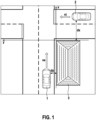
- Fig. 1 shows a schematic plan view of an intersection where a building blocks the view.
- X and y denote orthogonal axes of a (spatially fixed) coordinate system.
- FIG. 1 An ego vehicle 1 approaching from below at speed ve is approaching the intersection.
- An opponent vehicle 2 is approaching the intersection from the right at speed vt.
- a building 3 on the right side of the road next to the lane of ego vehicle 1 blocks the line of sight between ego vehicle 1 and opponent vehicle 2. Consequently, neither the driver of ego vehicle 1 nor sensors on board ego vehicle 1 can detect opponent vehicle 2. If both vehicles 1 and 2 were to continue driving straight ahead, a collision would occur. A conventional vision-based braking assistant would fail and could not prevent the collision.
- the situation shown is often found in urban traffic. However, the invention is not limited to this situation. It is also effective in other situations of this type, such as roundabouts, intersections on curves, side streets with parked vehicles, cycle path intersections, railway crossings, tram crossings, when there is heavy traffic around the ego vehicle, when there is an oncoming vehicle in the ego vehicle's lane, when there is a slow vehicle in front of the ego vehicle on a curve, etc.
- the present invention comprises a first braking application with moderate braking force, which is triggered early enough by receiving V2X data, before the opposing vehicle 2 is visible, so that the collision can be avoided. Due to the high safety requirements of an emergency braking function, the V2X data only triggers moderate braking, since emergency braking requires a higher safety level (e.g. ASIL B) due to the strong deceleration of, for example, 9 ms -2 .
- ASIL B e.g. ASIL B
- Fig. 2 shows a schematic view of an embodiment of a device or method for performing emergency braking.
- the first three boxes on the left denote the first data 11, the second data 12, and the third data 13. These data 11, 12, 13 are combined to form an environmental model 14 of the ego vehicle. Collision probabilities 15 are calculated based on the environmental model 14 and the third data 13. A decision is then made as to whether a first braking stage S1 and/or a second braking stage S2 should be performed. Based on this decision, braking signals are generated and output to a braking system 4 of the ego vehicle.
- the first data 11 is collected by sensors on board the ego vehicle 1.
- Vision-based sensors on board are required to detect the enemy vehicle 2 with a high functional safety level and serve as the data source for initiating the second braking application, the emergency braking with maximum braking force. They can consist of a single sensor, a combination of similar sensors, or a combination of different sensor technologies (such as radar, video, lidar, or ultrasound) to meet the functional safety level and sensor range requirements.
- the second data 12 are acquired by means of V2X and relate to the opponent vehicle 2.
- the second data 12 comprise at least a position, a direction and a speed of the opponent vehicle 2.
- the ego vehicle 1 comprises a suitable V2X interface.
- the second data 12 includes an acceleration, a brake pressure, a yaw rate, a vehicle type, dimensions, a past trajectory, and/or a planned trajectory, e.g., in the case of a self-driving opponent vehicle.
- the sender of the V2X communication can be the opponent vehicle 2 itself (V2V), an infrastructure (V2I) equipped with sensors to detect the opponent vehicle and a V2X communication unit, or a third road user that can detect the opponent vehicle and pass on the information about the opponent vehicle via V2X.
- V2V opponent vehicle 2 itself
- V2I infrastructure
- V2X communication unit a third road user that can detect the opponent vehicle and pass on the information about the opponent vehicle via V2X.
- the third data 13 describes the state of the ego-vehicle 1, in particular its position, speed, and direction.
- further state information of the ego-vehicle 1 that improves the movement prediction of the ego-vehicle 1, such as acceleration, braking pressure, yaw rate, vehicle type, dimensions, a past trajectory, and/or a planned trajectory in the case of an automatically driving ego-vehicle 1, can be recorded.
- the first data 11, the second data 12, and the third data 13 can be combined to generate an environmental model 14 of the ego vehicle.
- collision probabilities 15 can be calculated.
- the environmental model 14 combines all information about states and trajectories and uncertainties or location probabilities in a unified representation (e.g., in a world or vehicle coordinate system). about the ego vehicle and all potential opponent vehicles.
- the environment model 14 can include additional information about the traffic situation and traffic regulations.
- Collision probabilities 15 between the ego vehicle and each potential adversary vehicle can, for example, be calculated by a specially configured device comprising a processor and a memory device, as well as suitable interfaces for inputting and outputting data. This requires a motion prediction for the ego vehicle and each potential adversary. This prediction takes into account all object data, including the existence probabilities and uncertainties from the environmental model 14 and the data components of the ego vehicle.
- a braking application device decides whether the ego vehicle applies the first braking application S1.
- this response pattern is a moderate braking intervention requiring only a relatively low ASIL level, which can be met through V2X communication, so this first braking stage S1 can be activated using information derived exclusively from the V2X communication (second data 12).
- the first braking intervention S1 can be limited to a maximum deceleration value of approximately 4 m/s 2 .
- the first braking application S1 can be applied with a constant deceleration value or with a deceleration value adapted to the need for collision avoidance.
- a high deceleration value close to the QM limit is used, as this reduces the prediction time and thus false-positive braking triggers.
- a first set of triggering conditions for the first braking S1 comprises the following criteria, all of which must preferably be met.
- a first condition is that, without braking, a collision between the ego vehicle and the opponent vehicle is predicted with a certain probability. Furthermore, second data 12 on the position and state of the opponent vehicle received via V2X communication must be available.
- a third condition for triggering is that a last possible time at which the first braking S1 that can avoid the collision has been achieved. In other words, the first braking S1 is initiated as late as possible to achieve the highest possible prediction accuracy and avoid false-positive braking.
- the latest possible time can be achieved by calculating a stopping distance under the assumption that the first braking action S1 is initiated at the current time. This condition is met if the currently remaining distance to the calculated collision position is less than the stopping distance. With this strategy, the ego vehicle should always come to a stop before the calculated collision position of the opponent vehicle. Alternatively, the latest possible time can be determined so that the ego vehicle can use the space behind the opponent vehicle after it has passed the path of the ego vehicle.
- the triggering time is preferably limited by a maximum value for the remaining time to collision in order to limit the prediction time to an upper limit and thus reduce false-positive braking.
- An example value for this maximum permissible time to collision is 2 to 2.5 seconds for urban speeds.
- the device for implementing the braking makes the decision as to whether the vehicle should perform the second braking application S2.
- This reaction pattern is an emergency braking application, which requires a high ASIL level (e.g. ASIL B), which cannot usually be met by data received via V2X communication alone. Therefore, the second braking application S2 is only triggered when there is a line of sight to the opposing vehicle and this can be detected by the on-board sensors, i.e. when initial data 11 is available.
- the deceleration value for the second braking application S2 is preferably close to an emergency braking application. A typical value is, for example, 9 m/s 2 .
- a second set of triggering conditions for the second braking S2 comprises the following criteria, which preferably all have to be met. According to a In the first condition, a collision between the ego vehicle and the opponent vehicle must be predicted with a certain probability if no braking or only the first braking S1 is performed. Alternatively, the second braking S2 can also be triggered completely independently of the first braking S1.
- Another mandatory requirement for the second braking S2 is that the position and state of the enemy vehicle are detected by the on-board sensors, i.e., that initial data 11 about the enemy vehicle is available. This ensures that the position, speed, direction, and acceleration of the enemy vehicle are detected with high reliability and safety.
- a further condition is that the last possible time at which the second braking action S2 can avoid the collision is reached.
- the strategies described above for the first braking action can also be applied here.
- the ego vehicle should come to a stop in an area ahead of the opponent vehicle.
- the reference number 4 in Fig. 2 A braking device is shown. This can, for example, be a component that transmits the required braking force to the brakes of the ego vehicle. This is usually a control unit of an ESC or ESP system ("Electronic Stability Control") with corresponding interfaces.
- Fig. 3 shows a chronological sequence of a method for performing braking according to an embodiment.
- the vertical axis indicates a deceleration (negative acceleration) in m/s 2 .
- the horizontal axis is the time axis.
- the thick line illustrates the temporal progression of the deceleration of the ego vehicle. The following describes the Fig. 3 marked times t1 to t6 are explained.
- the enemy vehicle is within communication range for V2X communication.
- second data 12 can be periodically transmitted via the enemy vehicle using V2X. received.
- the probability of the enemy vehicle's existence can be increased with each received message, which includes, for example, the second data 12 and a timestamp.
- the present method or the corresponding system can then calculate the collision probability with the enemy vehicle and the corresponding remaining time to collision as described above.
- Time t2 denotes the latest possible trigger point for avoiding a collision by means of the first braking action S1.
- the first braking action S1 should be triggered to avoid a collision.
- not all conditions of the first set of conditions are yet met.
- the remaining time until collision is still greater than a specified maximum value for triggering the first braking action S1.
- Time t5 represents the latest possible time for triggering the second braking action S2 to avoid the collision. At this moment, all second conditions are met, and the second braking action S2 is triggered by the second trigger signal TS2.
- the second braking force B2 is applied to achieve a maximum deceleration of 9 m/ s2 .
- the automatic braking intervention is deactivated.
- the ego vehicle has come to a standstill and/or a collision is no longer predicted.
- the ego vehicle behind the enemy vehicle that has completely passed the path of the ego vehicle.
- the triggering of the first braking action S1 can be limited to cases in which an obstacle that prevents direct detection of the opposing vehicle is directly detected by the on-board sensors.
- second data 12 about the opposing vehicle is collected via V2X but no first data 11 is available, it can be concluded that an obstacle is blocking direct detection of the opposing vehicle. This check can also be made dependent, for example, on the opposing vehicle being within range of the on-board sensors.
- the triggering of the first braking action S1 can also be limited to cases in which the ego vehicle does not have the right of way.
- the first braking action S1 is generally triggered at a later time than the driver would start braking if they recognized the existing right-of-way situation. If the driver fails to brake for any reason, the method according to the invention can prevent an accident.
- the first braking S1 is not triggered if the opponent vehicle violates the right-of-way of the ego vehicle.
- a false-positive braking is likely if the opponent vehicle has not yet begun its braking maneuver. Omitting these situations has a great potential to reduce the occurrence of false-positive braking altogether.
- the process requires information about applicable right-of-way rules, which can be obtained, for example, from map information and/or the recognition of traffic signs and traffic lights.
- driver decelerate in a range of up to 3 m/s 2 to cope with situations in urban environments.
- the first braking application S1 can therefore be delayed until it is unlikely that the opponent vehicle will decelerate and/or swerve. This can be achieved if the first braking application S1 is only allowed to be initiated, for example, if the opponent vehicle would have to brake with an above-average deceleration, e.g., greater than 3 m/s 2 , to avoid a collision with the ego vehicle. This restriction can reduce false-positive braking applications. The same condition can also be applied to braking applications by the driver of the ego vehicle.
- the absence of the first data 11 about the opposing vehicle may have reasons other than obstructed vision due to an obstacle.
- the sensor range may be limited by weather conditions such as fog, snow, or heavy rain, or by glare (low) sun, or by dust, dirt, or snow on the sensor itself.
- the sensors may have poor quality or measurement accuracy.
- Other reasons include a malfunction of one or more on-board sensors.
- the first braking S1 based on the second data 12 received via V2X can prevent collisions.
Landscapes
- Engineering & Computer Science (AREA)
- Transportation (AREA)
- Mechanical Engineering (AREA)
- Automation & Control Theory (AREA)
- Traffic Control Systems (AREA)
Applications Claiming Priority (1)
| Application Number | Priority Date | Filing Date | Title |
|---|---|---|---|
| DE102023212830.6A DE102023212830A1 (de) | 2023-12-18 | 2023-12-18 | Verfahren und Vorrichtung zum Durchführen einer Bremsung in einem Ego-Fahrzeug |
Publications (1)
| Publication Number | Publication Date |
|---|---|
| EP4574591A1 true EP4574591A1 (fr) | 2025-06-25 |
Family
ID=92801364
Family Applications (1)
| Application Number | Title | Priority Date | Filing Date |
|---|---|---|---|
| EP24200546.0A Pending EP4574591A1 (fr) | 2023-12-18 | 2024-09-16 | Procédé et dispositif pour effectuer un freinage dans un véhicule autonome |
Country Status (3)
| Country | Link |
|---|---|
| EP (1) | EP4574591A1 (fr) |
| CN (1) | CN120171517A (fr) |
| DE (1) | DE102023212830A1 (fr) |
Citations (5)
| Publication number | Priority date | Publication date | Assignee | Title |
|---|---|---|---|---|
| US20070046449A1 (en) * | 2005-08-31 | 2007-03-01 | Honda Motor Co., Ltd. | Travel safety apparatus for vehicle |
| US9566959B2 (en) * | 2012-02-14 | 2017-02-14 | Wabco Gmbh | Method for determining an emergency braking situation of a vehicle |
| US20200257308A1 (en) | 2019-02-07 | 2020-08-13 | Ford Global Technologies, Llc | Autonomous vehicle systems utilizing vehicle-to-vehicle communication |
| FR3123616A1 (fr) | 2021-06-02 | 2022-12-09 | Psa Automobiles Sa | Procédé et dispositif de détermination d’un risque de collision entre véhicules configurés pour communiquer en V2X |
| US20230070314A1 (en) | 2021-09-07 | 2023-03-09 | Aptiv Technologies Limited | Estimated-Acceleration Determination for Automatic Emergency Braking |
-
2023
- 2023-12-18 DE DE102023212830.6A patent/DE102023212830A1/de active Pending
-
2024
- 2024-09-16 EP EP24200546.0A patent/EP4574591A1/fr active Pending
- 2024-12-18 CN CN202411868482.2A patent/CN120171517A/zh active Pending
Patent Citations (6)
| Publication number | Priority date | Publication date | Assignee | Title |
|---|---|---|---|---|
| US20070046449A1 (en) * | 2005-08-31 | 2007-03-01 | Honda Motor Co., Ltd. | Travel safety apparatus for vehicle |
| US9566959B2 (en) * | 2012-02-14 | 2017-02-14 | Wabco Gmbh | Method for determining an emergency braking situation of a vehicle |
| US20200257308A1 (en) | 2019-02-07 | 2020-08-13 | Ford Global Technologies, Llc | Autonomous vehicle systems utilizing vehicle-to-vehicle communication |
| DE102020102965A1 (de) * | 2019-02-07 | 2020-08-13 | Ford Global Technologies, Llc | Autonome fahrzeugsysteme, die fahrzeug-zu-fahrzeug-kommunikation verwenden |
| FR3123616A1 (fr) | 2021-06-02 | 2022-12-09 | Psa Automobiles Sa | Procédé et dispositif de détermination d’un risque de collision entre véhicules configurés pour communiquer en V2X |
| US20230070314A1 (en) | 2021-09-07 | 2023-03-09 | Aptiv Technologies Limited | Estimated-Acceleration Determination for Automatic Emergency Braking |
Also Published As
| Publication number | Publication date |
|---|---|
| CN120171517A (zh) | 2025-06-20 |
| DE102023212830A1 (de) | 2025-06-18 |
Similar Documents
| Publication | Publication Date | Title |
|---|---|---|
| EP1554604B1 (fr) | Procede et dispositif pour empecher la collision de vehicules | |
| EP2404195B1 (fr) | Procédé pour la détection automatique d'une manoeuvre de conduite d'un véhicule automobile et système d'assistance au conducteur comprenant ce procédé | |
| EP2681089B1 (fr) | Limitation de l'activation d'un système d'aide à l'évitement | |
| DE102008036131B4 (de) | Verfahren und Vorrichtung zur Erkennung der Verkehrssituation in einer Fahrzeugumgebung | |
| DE112020005298T5 (de) | Fahrzeugsteuersystem und fahrzeugsteuerverfahren | |
| DE102016122686B4 (de) | Verfahren zum Informieren eines Verkehrsteilnehmers über eine Verkehrssituation | |
| EP3027479B1 (fr) | Fourniture d'un modèle d'environnement en cas de panne d'un capteur d'un véhicule | |
| DE112020005236T5 (de) | Fahrzeugsteuergerät und fahrzeugsteuersystem | |
| DE102020207928A1 (de) | Vorrichtung zur unterstützung des fahrens eines fahrzeugs und verfahren dafür | |
| WO2006072342A1 (fr) | Procede permettant de faire fonctionner un systeme anti-collision ou reducteur des consequences de collision d'un vehicule et systeme anti-collision ou reducteur des consequences de collision | |
| DE102020123658B4 (de) | Fahrerassistenzapparat und verfahren dafür | |
| DE102006047131A1 (de) | Verfahren zum automatischen Steuern eines Fahrzeugs | |
| WO2017008800A1 (fr) | Commande prédictive d'un véhicule automobile | |
| DE102007042792A1 (de) | Verfahren zur Umfeldüberwachung für ein Kraftfahrzeug | |
| WO2014170432A1 (fr) | Procédé et système permettant d'éviter qu'un véhicule suiveur ne heurte un véhicule immédiatement précédent, ainsi qu'utilisation du système | |
| DE102018105912A1 (de) | Kollisionsvermeidungseinrichtung | |
| DE102018215509A1 (de) | Verfahren und Vorrichtung zum Betrieb eines zumindest teilweise automatisiert betriebenen ersten Fahrzeugs | |
| DE102017204878A1 (de) | Verfahren zum Betreiben eines Fahrzeugkonvois | |
| DE102004057060A1 (de) | Fahrassistenzvorrichtung sowie Verfahren zur Erkennung von auf der eigenen Fahrspur entgegenkommenden Fahrzeugen | |
| DE102017205495A1 (de) | Vorrichtung und Verfahren zum Fokussieren von Sensoren im fahrdynamischen Grenzbereich für ein Kraftfahrzeug | |
| DE102015208697A1 (de) | Längsführendes Fahrerassistenzsystem eines Kraftfahrzeugs mit situationsabhängiger Parametrierung | |
| DE102017201196A1 (de) | Verfahren zum Betreiben eines Fahrzeugkonvois | |
| EP3803830B1 (fr) | Procédé permettant de mettre en garde un conducteur d'un véhicule automobile contre une collision | |
| WO2009109244A2 (fr) | Système de sécurité coopératif pour véhicules automobiles | |
| WO2016124368A1 (fr) | Procédé pour faire fonctionner un véhicule, programme informatique, support d'enregistrement lisible par ordinateur, unité de commande électronique |
Legal Events
| Date | Code | Title | Description |
|---|---|---|---|
| PUAI | Public reference made under article 153(3) epc to a published international application that has entered the european phase |
Free format text: ORIGINAL CODE: 0009012 |
|
| STAA | Information on the status of an ep patent application or granted ep patent |
Free format text: STATUS: THE APPLICATION HAS BEEN PUBLISHED |
|
| AK | Designated contracting states |
Kind code of ref document: A1 Designated state(s): AL AT BE BG CH CY CZ DE DK EE ES FI FR GB GR HR HU IE IS IT LI LT LU LV MC ME MK MT NL NO PL PT RO RS SE SI SK SM TR |
|
| STAA | Information on the status of an ep patent application or granted ep patent |
Free format text: STATUS: REQUEST FOR EXAMINATION WAS MADE |
|
| 17P | Request for examination filed |
Effective date: 20260102 |