EP4570943A1 - Molybdän-sputtertarget, verfahren zur herstellung davon und verfahren zur herstellung eines sputterfilms unter verwendung des molybdän-sputtertargets - Google Patents
Molybdän-sputtertarget, verfahren zur herstellung davon und verfahren zur herstellung eines sputterfilms unter verwendung des molybdän-sputtertargets Download PDFInfo
- Publication number
- EP4570943A1 EP4570943A1 EP23860426.8A EP23860426A EP4570943A1 EP 4570943 A1 EP4570943 A1 EP 4570943A1 EP 23860426 A EP23860426 A EP 23860426A EP 4570943 A1 EP4570943 A1 EP 4570943A1
- Authority
- EP
- European Patent Office
- Prior art keywords
- molybdenum
- target
- less
- sputtering
- sputtering target
- Prior art date
- Legal status (The legal status is an assumption and is not a legal conclusion. Google has not performed a legal analysis and makes no representation as to the accuracy of the status listed.)
- Pending
Links
Images



Classifications
-
- C—CHEMISTRY; METALLURGY
- C23—COATING METALLIC MATERIAL; COATING MATERIAL WITH METALLIC MATERIAL; CHEMICAL SURFACE TREATMENT; DIFFUSION TREATMENT OF METALLIC MATERIAL; COATING BY VACUUM EVAPORATION, BY SPUTTERING, BY ION IMPLANTATION OR BY CHEMICAL VAPOUR DEPOSITION, IN GENERAL; INHIBITING CORROSION OF METALLIC MATERIAL OR INCRUSTATION IN GENERAL
- C23C—COATING METALLIC MATERIAL; COATING MATERIAL WITH METALLIC MATERIAL; SURFACE TREATMENT OF METALLIC MATERIAL BY DIFFUSION INTO THE SURFACE, BY CHEMICAL CONVERSION OR SUBSTITUTION; COATING BY VACUUM EVAPORATION, BY SPUTTERING, BY ION IMPLANTATION OR BY CHEMICAL VAPOUR DEPOSITION, IN GENERAL
- C23C14/00—Coating by vacuum evaporation, by sputtering or by ion implantation of the coating forming material
- C23C14/22—Coating by vacuum evaporation, by sputtering or by ion implantation of the coating forming material characterised by the process of coating
- C23C14/34—Sputtering
- C23C14/3407—Cathode assembly for sputtering apparatus, e.g. Target
- C23C14/3414—Metallurgical or chemical aspects of target preparation, e.g. casting, powder metallurgy
-
- B—PERFORMING OPERATIONS; TRANSPORTING
- B22—CASTING; POWDER METALLURGY
- B22F—WORKING METALLIC POWDER; MANUFACTURE OF ARTICLES FROM METALLIC POWDER; MAKING METALLIC POWDER; APPARATUS OR DEVICES SPECIALLY ADAPTED FOR METALLIC POWDER
- B22F3/00—Manufacture of workpieces or articles from metallic powder characterised by the manner of compacting or sintering; Apparatus specially adapted therefor ; Presses and furnaces
- B22F3/12—Both compacting and sintering
- B22F3/14—Both compacting and sintering simultaneously
-
- C—CHEMISTRY; METALLURGY
- C22—METALLURGY; FERROUS OR NON-FERROUS ALLOYS; TREATMENT OF ALLOYS OR NON-FERROUS METALS
- C22C—ALLOYS
- C22C27/00—Alloys based on rhenium or a refractory metal not mentioned in groups C22C14/00 or C22C16/00
- C22C27/04—Alloys based on tungsten or molybdenum
-
- C—CHEMISTRY; METALLURGY
- C23—COATING METALLIC MATERIAL; COATING MATERIAL WITH METALLIC MATERIAL; CHEMICAL SURFACE TREATMENT; DIFFUSION TREATMENT OF METALLIC MATERIAL; COATING BY VACUUM EVAPORATION, BY SPUTTERING, BY ION IMPLANTATION OR BY CHEMICAL VAPOUR DEPOSITION, IN GENERAL; INHIBITING CORROSION OF METALLIC MATERIAL OR INCRUSTATION IN GENERAL
- C23C—COATING METALLIC MATERIAL; COATING MATERIAL WITH METALLIC MATERIAL; SURFACE TREATMENT OF METALLIC MATERIAL BY DIFFUSION INTO THE SURFACE, BY CHEMICAL CONVERSION OR SUBSTITUTION; COATING BY VACUUM EVAPORATION, BY SPUTTERING, BY ION IMPLANTATION OR BY CHEMICAL VAPOUR DEPOSITION, IN GENERAL
- C23C14/00—Coating by vacuum evaporation, by sputtering or by ion implantation of the coating forming material
- C23C14/06—Coating by vacuum evaporation, by sputtering or by ion implantation of the coating forming material characterised by the coating material
- C23C14/14—Metallic material, boron or silicon
Definitions
- the present disclosure relates to a molybdenum sputtering target, a method for producing the same, and a method for producing a sputtering film using a molybdenum sputtering target.
- Sputtering targets (hereinafter, also referred to as "targets") containing a metal such as molybdenum are used for, for example, forming light-shielding films for lithography masks.
- targets a metal such as molybdenum
- characteristics required for the targets have also become higher, and currently, there has been a demand for a target that can further reduce the generation of impurity particles (so-called particles) of a metal oxide or the like during formation of a sputtering film.
- particles impurity particles
- an increase in the density, a reduction in the oxygen content, and a reduction in the crystal grain size of targets have hitherto been studied.
- PTL 1 reports targets having fine grain sizes; targets having an average grain size of 2 ⁇ m and targets having an average grain size of 8 ⁇ m are reported in Comparative Examples 1 and 2 and Comparative Examples 7 and 8, respectively.
- the density of each of the targets is not sufficiently improved, and arcing is likely to occur.
- Example No. 27 a target having an oxygen content of 85 ppm; however, the average grain size measured by the intercept method from the SEM image of Fig. 5 is about 15 ⁇ m.
- PTL 3 reports that a molybdenum sintered body immediately after HIP sintering has a density of 100% and an average crystal grain size of 11 ⁇ m. As described above, in the sintered body immediately after sintering, an increase in the density and a reduction in the grain size are in a trade-off relationship, and it is difficult to further reduce the grain size with HIP sintering alone.
- An object of the present disclosure is to provide at least one of a molybdenum sputtering target that has a high density and a low oxygen content, that further has fine crystal grains, and that achieves a reduction in the generation of particles during deposition, a method for producing the same, and a method for producing a sputtering film using the molybdenum sputtering target.
- the present invention is defined in the claims, and the gist of the present disclosure is as follows.
- the present disclosure provides at least one of a molybdenum sputtering target that has a high density and a low oxygen content, that further has fine crystal grains, and that achieves a reduction in the generation of particles during deposition, a method for producing the same, and a method for producing a sputtering film using the molybdenum sputtering target.
- a target of the present embodiment is a molybdenum sputtering target containing molybdenum.
- the target of the present embodiment is more preferably a metal sputtering target made of molybdenum.
- the oxygen content of the target of the present embodiment is 100 ppm by mass or less, more preferably 30 ppm by mass or less, still more preferably 20 ppm by mass or less, still further more preferably 10 ppm by mass or less, particularly preferably 7 ppm by mass or less.
- the oxygen content of the target is within the above range, entry of oxygen in a film can be reduced during deposition to suppress the generation of particles caused by entry of oxygen.
- the target of the present embodiment can provide a sputtering film having higher crystallinity.
- the oxygen content may be 0 ppm by mass or more, more than 0 ppm by mass, 0.1 ppm by mass or more, 0.5 ppm by mass or more, or 1 ppm by mass or more.
- the oxygen content is preferably 0 ppm by mass or more and 100 ppm by mass or less, more preferably more than 0 ppm by mass and 30 ppm by mass or less, still more preferably 0.1 ppm by mass or more and 20 ppm by mass or less.
- the oxygen content of the target can be measured with an oxygen/nitrogen analyzer (apparatus name: ON736, manufactured by LECO Corporation).
- the target of the present embodiment contains crystal grains, and an average crystal grain size (average grain size) of the crystal grains is less than 10 ⁇ m, more preferably 8 ⁇ m or less, still more preferably 5 ⁇ m or less, still further more preferably 4 ⁇ m or less, particularly preferably 2 ⁇ m or less.
- the average crystal grain size is more than 0 ⁇ m, preferably 0.1 ⁇ m or more, or 1 ⁇ m or more.
- the average crystal grain size is preferably more than 0 ⁇ m and 8 ⁇ m or less, more preferably 0.1 ⁇ m or more and 5 ⁇ m or less, still more preferably 1 ⁇ m or more and 4 ⁇ m or less.
- the average crystal grain size is in a range of less than 10 ⁇ m, the generation of particles during deposition is reduced, and detachment of redeposited sputtered particles can also be suppressed while an abnormal discharge is suppressed.
- the measurement of the average crystal grain size can be performed using scanning electron microscope-electron backscatter diffraction (hereinafter, also referred to as "SEM-EBSD").
- SEM-EBSD scanning electron microscope-electron backscatter diffraction
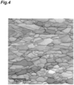
- the microstructure of the target is observed under the following measurement conditions and using the following programs, and the measurement can be performed for all observed crystal grains using an analysis program (for example, Aztec Crystal).
- a rotation angle between adjacent measurement points that is, the orientation difference (°) between measurement points is measured by EBSD in a SEM image, and a closed loop with continuous and uninterrupted pixel boundaries whose rotation angle exceeds 10° is regarded as a crystal grain boundary, and the region in the loop is defined as one crystal grain.
- the diameter of a circle having an area equivalent to the area of the region constituting a crystal grain is regarded as a grain size of the crystal grain, and the arithmetic mean of the grain sizes of all crystal grains measured can be calculated as the average crystal grain size.
- Figs. 1 and 2 are schematic views of a target.
- Fig. 1 is a schematic top view of the target for illustrating an observation region A
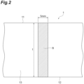
- Fig. 2 is a schematic sectional view of the target for illustrating a sampling portion B.
- the shape of the target is not particularly limited; however, in Figs. 1 and 2 , the description will be made on the assumption that the target has a disk shape.
- a sputtering surface 11 is a surface facing an object on which a film is to be formed, such as a substrate, during deposition and is a surface that comes in contact with an atmosphere gas converted into plasma.
- a bonding surface 12 is a surface to be joined to a backing plate. As illustrated in Fig.
- the sputtering surface 11 and the bonding surface 12 each correspond to a flat surface of the disk (hereinafter, the sputtering surface is also referred to as a "front surface”, and the bonding surface is also referred to as a "back surface” for the sake of convenience).
- an annular region on a circular sputtering surface 11 of a target 1 is defined as an observation region A.
- the observation region A is a region located between a circle centered on O and having a radius of 0.5R and a circle centered on O and having a radius of 0.75R.
- the observation region A is a region located between a rectangle in which the distance from P, which is the intersection of the diagonal lines, to the outer periphery is 0.5PQ and a rectangle in which the distance from P, which is the intersection of the diagonal lines, to the outer periphery is 0.75PQ.
- a region of 5 mm in width ⁇ t (mm) in overall thickness is defined as a sampling portion B (see Fig.
- the average crystal grain size can be determined by SEM-EBSD.
- the sampling portion B may be selected in any manner as long as the portion is located within the observation region A. In the present Description, dividing a target by cutting the target parallel to the sputtering surface will be described later. Also for each of the resulting divided segments, a region of 5 mm in width ⁇ t' (mm) in overall thickness of the divided segment is referred to as a "sampling portion B'" as in the sampling portion B. Measurement conditions and programs used for SEM-EBSD are described below.
- a sample may be prepared by cutting a target using a common cutting method (which may be, for example, a cutting method with at least one of a fine cutter and a water jet) to expose a cross section of the target.
- a common cutting method which may be, for example, a cutting method with at least one of a fine cutter and a water jet
- the sample may be pretreated by being mirror-polished with SiC abrasive paper and by buffing, followed by electrolytic etching with a 5 vol% aqueous solution of sulfuric acid.
- the average KAM value of the target of the present embodiment is preferably 1° or less, more preferably 0.5° or less or 0.4° or less. This reduces distortion inside the target to reduce the occurrence of cracking and warpage during machining and easily reduces the cracking of the sputtering surface of the target and the generation of particles during deposition to thereby stabilize the etching rate.
- the average KAM value is calculated from the arithmetic mean of the KAM values at all the measurement points.
- the average KAM value may be 0° or more, or 0.1 ° or more.
- the average KAM value is preferably 0° or more and 1° or less, more preferably 0° or more and 0.5° or less, still more preferably 0.1° or more and 0.4° or less.
- the maximum deviation of the average crystal grain size of the target of the present embodiment in a depth direction is preferably 3 ⁇ m or less, more preferably 1 ⁇ m or less.
- maximum deviation is 3 ⁇ m or less, the deposition rate of a sputtering film is likely to be uniform.
- the maximum deviation may be less than 1 ⁇ m, 0.8 ⁇ m or less, 0.6 ⁇ m or less, 0.4 ⁇ m or less, 0.2 ⁇ m or less, or 0.1 ⁇ m or less.
- the maximum deviation can be, for example, 0 ⁇ m or more, 0.01 ⁇ m or more, 0.03 ⁇ m or more, or 0.05 ⁇ m or more.
- the maximum deviation is preferably 0 ⁇ m or more and 3 ⁇ m or less, more preferably 0.01 ⁇ m or more and less than 1 ⁇ m, and still more preferably 0.03 ⁇ m or more and 0.2 ⁇ m or less.
- the depth direction refers to the thickness direction of the target.
- the maximum deviation of the average crystal grain size in the depth direction refers to the maximum deviation between the average crystal grain sizes on a surface on the sputtering surface side of the sampling portion B' of each of three divided segments prepared by cutting the target in a direction parallel to the sputtering surface at positions at which the target is divided into three equal segments in the depth direction.
- the maximum deviation is determined by, for example, cutting the target, subsequently subjecting each divided segment to surface polishing, calculating the average crystal grain size in each divided segment, and calculating the difference between the maximum value and the minimum value of the average crystal grain sizes.
- the relative density of the target of the present embodiment is 99.6% or more and is preferably 99.7% or more, 99.8% or more, 99.9% or more, 99.95% or more, or 99.99% or more. If the relative density is less than 99.6%, particles are likely to be generated. A relative density of more than 99.6% improves the strength of the target to facilitate the application of a high discharge power to the target. This improves the deposition rate in the case of forming a sputtering film by sputtering the target and tends to increase productivity of a sputtering film.
- the relative density is 100% or less.
- the relative density is preferably 99.6% or more and 100% or less, more preferably 99.9% or more and 100% or less, still more preferably 99.99% or more and 100% or less.
- the relative density of the target can be calculated by the following method. Specifically, a measured density of the target is measured in accordance with JIS R 1634, and the measured density is divided by the true density to calculate the relative density.
- the true density of molybdenum may be 10.22 g/cm 3 .
- the area of the sputtering surface of the target of the present embodiment is not particularly limited but is preferably 200 cm 2 or more, more preferably 350 cm 2 or more, still more preferably 800 cm 2 or more.
- An area of the sputtering surface of 200 cm 2 or more can increase the deposition area of a sputtering film. Accordingly, a film with a large area which usually needs to be formed using a plurality of targets can also be formed using a single target. Moreover, mixing of impurities from boundary portions between targets can be suppressed.
- the upper limit of the area of the sputtering surface is not particularly limited but is, for example, 3,000 cm 2 , 2,000 cm 2 , or 1,500 cm 2 .
- the area of the sputtering surface can be calculated, as the area of a circle, using the diameter of the sputtering surface.
- the diameter of the sputtering surface can be measured with a vernier caliper or a three-dimensional measuring device.
- the area of the sputtering surface is preferably 200 cm 2 or more and 3,000 cm 2 or less, more preferably 350 cm 2 or more and 3,000 cm 2 or less, still more preferably 800 cm 2 or more and 2,000 cm 2 or less.
- the purity of the target of the present embodiment is not particularly limited but is preferably 99.9% or more, more preferably 99.99% or more, still more preferably 99.995% or more.
- the expression "the purity of the target is 99.9% or more” means that the content of molybdenum metal contained in the target of the present embodiment is 99.9% by mass or more, that is, the content of metal elements (impurity metal elements) other than molybdenum metal contained in the target of the present embodiment is 0.1% by mass or less.
- the purity is 99.9% or more, the generation of particles originating from impurities is more likely to be suppressed.
- “4N” represents a purity of 99.99% or more
- “5N” represents a purity of 99.999% or more
- “4N8” represents a purity of 99.998% or more.
- the purity of a target is calculated based only on metal elements for both powders and sintered bodies, and the oxygen content is not included in the calculation.
- the purity of the target of the present embodiment can be measured by glow discharge mass spectrometry (GDMS).
- GDMS glow discharge mass spectrometry
- a specimen with a size of 10 to 25 mm ⁇ 10 to 25 mm ⁇ 0.5 to 15 mm is cut out from the target to prepare a measurement sample.
- the measurement sample is pretreated by being subjected to polishing with SiC abrasive paper (#800), followed by ultrasonic cleaning in pure water for 10 minutes, dehydration with an alcohol, hot-air drying, and subsequent vacuum packing.
- the content of impurities impurity metal elements
- ASTM F 1593 the purity may be calculated on the basis of the content of impurities and the following formula.
- Purity % 100 ⁇ contentofimpurities
- the target of the present embodiment can be produced by a method including a refining step that includes a plastic working step of subjecting a molybdenum ingot to plastic working treatment to obtain a plastically worked product, and a heat treatment step of subjecting the plastically worked product to heating treatment.
- the method for producing the target of the present embodiment includes a refining step of refining crystal grains in a molybdenum ingot, in which the refining step includes a plastic working step of subjecting the molybdenum ingot to plastic working to obtain a plastically worked product and a heat treatment step of subjecting the plastically worked product to heating treatment.
- the method for producing the target of the present embodiment may include, before the refining step, an ingot preparation step of sintering, or melting and then cooling molybdenum metal (hereinafter, also referred to as a "raw material” or “raw material metal”) to obtain an ingot.
- an ingot preparation step of sintering or melting and then cooling molybdenum metal (hereinafter, also referred to as a "raw material” or “raw material metal”) to obtain an ingot.
- an ingot is prepared from the raw material by a sintering method or a melting method.
- the form of the raw material is not limited as long as an ingot is obtained by sintering, or melting and then cooling the raw material, and such a form may be, for example, a powdered, granular, or flaky form.
- the purity of the raw material metal is preferably 99.99% or more.
- the oxygen content of the raw material is 100 ppm by mass or less, preferably 30 ppm by mass or less, more preferably 20 ppm by mass or less, still more preferably 10 ppm by mass or less, particularly preferably 7 ppm by mass or less.
- a reduction in the oxygen content of the raw material enables a reduction in the oxygen content of the target.
- the oxygen content is preferably low but may be more than 0 ppm by mass, or 1 ppm by mass or more.
- the oxygen content of the raw material is preferably more than 0 ppm by mass and 100 ppm by mass or less, more preferably more than 0 ppm by mass and 30 ppm by mass or less, still more preferably 1 ppm by mass or more and 20 ppm by mass or less.
- the sintering method an ingot is obtained by sintering the raw material.
- the type of sintering method may be, for example, at least one of a molding-sintering method and a pressure sintering method. Either sintering method may be used, but the pressure sintering method is preferably employed in order to improve the density.
- Examples of the pressure sintering method include a hot press method and a hot isostatic press method (hereinafter, also referred to as a "HIP method"), and the HIP method, which has a higher pressurizing capability, is preferably used.
- the firing temperature is not particularly limited, but is preferably 1,000°C or higher and 1,500°C or lower, more preferably 1,200°C or higher and 1,450°C or lower.
- the density and the average crystal grain size of a sintered body before rolling treatment can be predetermined values.
- the sintered body obtained can be used as the ingot.
- an ingot is obtained by melting the raw material by heating to a temperature equal to or higher than the melting point and then performing cooling.
- the method of melting is not particularly limited as long as the oxygen content of the target becomes 100 ppm by mass or less.
- the method of melting may be, for example, one or more selected from the group consisting of skull melting, arc melting, and electron beam melting. In order to reduce the oxygen content and impurities in the target, electron beam melting is preferred.
- the relative density of the ingot for the plastic working step is preferably 90% or more, more preferably 95% or more.
- the relative density of the ingot may be, for example, 100% or less.
- the relative density of the ingot is preferably 90% or more and 100% or less, more preferably 95% or more and 100% or less.
- the average crystal grain size of the ingot is preferably 10 ⁇ m or more and 400 ⁇ m or less.
- the average crystal grain size is 10 ⁇ m or more, the density of the target to be obtained is improved.
- the average crystal grain size of the ingot is 400 ⁇ m or less, the average crystal grain size of the target to be obtained tends to be reduced, and the number of times of plastic working treatment described later is decreased to thereby improve productivity of the target.
- the refining step is a step of refining crystal grains in the molybdenum ingot.
- the refining step includes a plastic working step of subjecting a molybdenum ingot to plastic working to obtain a plastically worked product, and a heat treatment step of subjecting the plastically worked product to heating treatment.
- crystal grains in the ingot are refined to provide a target of the present embodiment having an average crystal grain size of less than 10 ⁇ m.
- the ingot is subjected to plastic working to prepare a plastically worked product.
- the resulting plastically worked product is further subjected to the heat treatment step to thereby refine crystal grains of the ingot, thus obtaining the target of the present embodiment.
- the ingot may be subjected to a grinding process to have a shape and a size suitable for plastic working.
- the processing method may be, for example, grinding with a surface grinder.
- the means for the plastic working is not particularly limited as long as the crystal microstructure of the ingot can be fractured by the method, and, for example, rolling mill rolls can be used.
- rolling mill rolls the prepared ingot is compressed by passing the ingot through a gap between a pair of rolling mill rolls, the gap having a width smaller than the thickness of the ingot. This provides a rolled product.
- the resulting rolled product may be repeatedly passed through a gap between a pair of rolling mill rolls.
- a step of passing an ingot or a rolled product through a gap between a pair of rolling mill rolls is also referred to as a "rolling pass" .
- the rolling treatment is preferably performed while a temperature of the ingot to be rolled (hereinafter, also referred to as a "rolling temperature") is 200°C or higher and 1,500°C or lower.
- the rolling temperature is more preferably 500°C or higher and 1,200°C or lower, still more preferably 700°C or higher and 1,000°C or lower.
- strain can be left in the whole rolled sheet (rolled product), and therefore, crystal grains are likely to be refined by the subsequent heat treatment.
- a rolling temperature of 500°C or higher can reduce the occurrence of cracking, and a rolling temperature of 1,200°C or lower can suppress coarsening of crystal grains due to dynamic recrystallization.
- the rolling reduction ratio of the ingot in each rolling pass is preferably set so as to be 6% or more and 20% or less of the thickness of the ingot before the rolling pass, more preferably 8% or more and 10% or less.
- the rolling reduction ratio is 6% or more, the difference in the amount of deformation between the surface and the inside of the ingot during rolling can be small to suppress an orientation imbalance in the depth direction after recrystallization.
- the rolling reduction ratio is 20% or less, cracking of the material can be reduced.
- strain can be uniformly introduced to the whole without cracking of the rolled product, enabling rolling in which the orientation imbalance is controlled.
- the temperature difference between rolling mill rolls and the ingot is preferably 500°C or less, more preferably 300°C or less.
- the difference between the roll temperature and the ingot temperature is 500°C or less, it is possible to reduce the occurrence of cracking caused by thermal stress due to the temperature gradient inside the ingot.
- the plastically worked product obtained by plastic working is further subjected to the heat treatment step to provide a heat-treated product in which crystal grains are refined.
- the heat treatment in the heat treatment step is performed at a temperature higher than the plastic working temperature in the immediately previous plastic working step.
- the heat treatment performed at a temperature equal to or higher than the plastic working temperature can release the strain introduced during plastic working to recrystallize metallic microstructure of molybdenum.
- the heat treatment temperature is preferably 500°C or higher and 1,300°C or lower, preferably 700°C or higher and 1,100°C or lower. This promotes recrystallization of the metallic microstructure to refine the crystal grains of the target.
- the plastically worked product is heated in a vacuum or inert gas atmosphere furnace at 1,300°C or lower, surface oxidation can be suppressed and an increase in the average crystal grain size tends to be less likely to occur, and thus a target of the present embodiment is likely to be obtained.
- the heat treatment temperature is 500°C or higher, the deformed texture after plastic working can be recrystallized, and uniform recrystallized microstructure can be obtained. Through the heat treatment step described above, a heat-treated product is obtained.
- the refining step may be repeatedly performed. Specifically, the heat-treated product obtained by subjecting the plastically worked product after the plastic working step to the heat treatment step may be subjected to the plastic working step and the heat treatment step again.
- the plastic working temperature in the second and subsequent refining steps is preferably lower than the plastic working temperature of an ingot or a plastically worked product in the immediately previous refining step. Specifically, the plastic working temperature is preferably 300°C or higher and lower than 800°C.
- strain can be further added while strain accumulated in the ingot or the plastically worked product in the immediately previous refining step is moderately maintained, strain can be uniformly provided inside the material, and crystal grains can be refined to reduce the grain size of the crystal grains.
- An oxide may be formed on the surface of the heat-treated product after the refining step, and the heat-treated product has a large surface roughness. Therefore, the heat-treated product is preferably subjected to a surface polishing process.
- the processing method is not particularly limited, and may be, for example, grinding with a surface grinder. In order to remove oxidized scale on the surface of the heat-treated product, a portion from the surface of the heat-treated product to a depth of 0.5 mm or more is preferably ground.
- the surface polishing process may be performed for at least a heat-treated product after the last heat treatment step.
- the obtained target may be joined (bonded) to a backing plate for use.
- the joining method include diffusion bonding, solder bonding, and friction stir welding, but the joining method is not particularly limited.
- the method for producing a sputtering film of the present embodiment includes a step of performing sputtering using the target of the present embodiment to produce a sputtering film.
- a substrate with a sputtering film 100 includes a substrate 10 and a sputtering film 20 formed on the substrate 10.
- Sputtering using the target of the present embodiment can suppress the generation of particles during deposition to provide a sputtering film with high film-thickness uniformity.
- Example of the substrate 10 include, but are not particularly limited to, a glass substrate and a quartz substrate.
- the temperature of the substrate 10 is not particularly limited but may be, for example, room temperature (25°C).
- the type of process gas during deposition is not particularly limited as long as the gas causes sputtering upon discharging, and the gas may be, for example, argon.
- the gas partial pressure during deposition is not particularly limited but may be, for example, 0.2 Pa or more and 2 Pa or less.
- the discharge power during deposition is not particularly limited but may be, for example, 2.5 W/cm 2 or more and 50 W/cm 2 or less.
- the deposition time is not particularly limited but may be, for example, 10 seconds or more and 100 seconds or less.
- the sputtering can be performed using a typical sputtering apparatus.
- the conditions for sputtering are not particularly limited, and the sputtering can be performed, for example, under the following conditions.
- a 350 mm ⁇ 350 mm ⁇ 350 mm soft iron can 210 kg of a molybdenum powder (purity, 5N (i.e., purity, 99.999% or more); oxygen content, 15 ppm by mass) was enclosed and subjected to HIP treatment under the following conditions.
- a molybdenum powder purity, 5N (i.e., purity, 99.999% or more); oxygen content, 15 ppm by mass
- the resulting HIP-treated product was taken out from the can, and ground and cut to adjust the shape thereof to obtain a disk-shaped ingot having a diameter of 180 mm and a thickness of 50 mm.
- the resulting ingot was heated to 800°C, and the heated ingot was then subjected to plastic working such that the compression rate in the thickness direction of the ingot did not exceed 10 mm/s.
- the material temperature decreased to 500°C or lower during working
- the ingot was reheated in a furnace at 800°C for 10 minutes, and the plastic working was repeated until the dimensions were 330 mm in diameter and 15 mm in thickness (that is, until the total rolling reduction ratio reached 70%) to obtain a plastically worked product.
- the resulting plastically worked product (worked ingot) was heat-treated in a hydrogen atmosphere at a heat treatment temperature of 900°C for three hours (180 minutes) to obtain a disk-shaped molybdenum material (hereinafter, also referred to as a "target") having a diameter of 330 mm and a thickness of 15 mm. This was used as a target of this example.
- a molybdenum powder (purity, 5N; oxygen content, 15 ppm by mass) was enclosed and subjected to HIP treatment under the following conditions.
- the resulting HIP-treated product was taken out from the can, and ground and cut to adjust the shape thereof to obtain a disk-shaped ingot having a diameter of 180 mm and a thickness of 50 mm.
- the resulting ingot was heated to 1,200°C, and the heated ingot was then subjected to plastic working such that the compression rate (pressurizing rate) in the thickness direction of the ingot did not exceed 10 mm/s (i.e., such that the maximum pressurizing rate was 10 mm/s).
- the ingot was reheated in a furnace at 1,200°C for 10 minutes, and the plastic working was repeated until the dimensions were 330 mm in diameter and 15 mm in thickness (that is, until the total rolling reduction ratio reached 70%) to obtain a plastically worked product.
- the resulting plastically worked product (worked ingot) was heat-treated in a hydrogen atmosphere at a heat treatment temperature of 1,100°C for three hours (180 minutes) to obtain a disk-shaped target having a diameter of 330 mm and a thickness of 15 mm. This was used as a target of this example.
- a molybdenum powder (purity, 4N8; oxygen content, 10 ppm by mass) was enclosed and subjected to HIP treatment under the following conditions.
- the resulting HIP-treated product was taken out from the can, and ground and cut to adjust the shape thereof to obtain a disk-shaped ingot having a diameter of 180 mm and a thickness of 50 mm.
- the resulting ingot was heated to 1,350°C, and the heated ingot was then subjected to plastic working such that the compression rate in the thickness direction of the ingot did not exceed 25 mm/s.
- the material temperature decreased to 1,100°C or lower during working
- the ingot was reheated in a furnace at 1,350°C for 10 minutes, and the plastic working was repeated until the dimensions were 330 mm in diameter and 15 mm in thickness (that is, until the total rolling reduction ratio reached 70%) to obtain a plastically worked product.
- the resulting plastically worked product (worked ingot) was heat-treated in a hydrogen atmosphere at a heat treatment temperature of 1,400°C for one hour (60 minutes) to obtain a disk-shaped target having a diameter of 330 mm and a thickness of 15 mm. This was used as a target of this example.
- a molybdenum powder (purity, 4N8; oxygen content, 10 ppm by mass) was enclosed and subjected to HIP treatment under the following conditions.
- the resulting HIP-treated product was taken out from the can, and ground and cut to adjust the shape thereof to obtain a disk-shaped ingot having a diameter of 180 mm and a thickness of 50 mm.
- the resulting ingot was heated to 1,350°C, and the heated ingot was then subjected to plastic working such that the compression rate in the thickness direction of the ingot did not exceed 25 mm/s.
- the material temperature decreased to 1,100°C or lower during working
- the ingot was reheated in a furnace at 1,350°C for 10 minutes, and the plastic working was repeated until the dimensions were 330 mm in diameter and 15 mm in thickness (that is, until the total rolling reduction ratio reached 70%) to obtain a plastically worked product.
- the resulting plastically worked product (worked ingot) was heat-treated in a hydrogen atmosphere at a heat treatment temperature of 1,500°C for one hour (60 minutes) to obtain a disk-shaped target having a diameter of 330 mm and a thickness of 15 mm. This was used as a target of this example.
- SEM-EBSD scanning electron microscope-electron backscatter diffraction
- a pretreatment was performed by mirror-polishing with SiC abrasive paper and buffing, followed by electrolytic etching with a 5 vol% aqueous solution of sulfuric acid.
- the oxygen content of the target was measured with an oxygen/nitrogen analyzer (apparatus name: ON736, manufactured by LECO Corporation). In this measurement, a prism-shaped sample with a size of 4 mm ⁇ 4 mm ⁇ 5 mm cut out from the target by cutting was used as a measuring object. The results are shown in Table 2.
- the measurement of the average crystal grain size was performed using SEM-EBSD (SEM: manufactured by JEOL Ltd., EBSD: manufactured by Oxford Instruments).
- SEM-EBSD SEM: manufactured by JEOL Ltd., EBSD: manufactured by Oxford Instruments
- the microstructure of the target was observed under the following measurement conditions and using the following programs, and the measurement was performed for all the observed crystal grains using the analysis program (Aztec Crystal).
- a rotation angle between adjacent measurement points that is, the orientation difference (°) between measurement points was measured by EBSD in a SEM image, and a closed loop with continuous and uninterrupted pixel boundaries whose rotation angle exceeded 10° was regarded as a crystal grain boundary, and the region in the loop was defined as one crystal grain.
- the diameter of a circle having an area equivalent to the area of the region constituting a crystal grain was regarded as a grain size of the crystal grain, and the arithmetic mean of the grain sizes of all crystal grains measured was calculated as the average crystal grain size. The results are shown in Table 2.
- the target was cut using a fine cutter in a direction parallel to the sputtering surface at positions at which the target was divided into three equal segments in the depth direction to obtain three divided segments.
- the average crystal grain size on a surface on the sputtering surface side of the sampling portion B' was calculated, and the difference between the maximum value and the minimum value of these average crystal grain sizes was determined as the maximum deviation ( ⁇ m).
- the results are shown in Table 2.
- the density of the target was measured in accordance with JIS R 1634 (Test methods of test methods for density and apparent porosity of fine ceramics), and the relative density (%) was calculated on the assumption that the true density of molybdenum is 10.22 g/cm 3 .
- the results are shown in Table 2.
- KAM Kernel Average Misorientation
- the targets of Examples subjected to the refining step of the ingot under the production conditions shown in Table 1 were each confirmed to satisfy a relative density of 99.6% or more, an average crystal grain size of less than 10 ⁇ m, and an oxygen content of 100 ppm by mass or less, as shown in Table 2.
- the targets of Comparative Examples each had a high relative density but had an average crystal grain size of more than 100 ⁇ m, as shown in Table 2.
- the targets of Examples each have crystal grains finer than the targets of Comparative Examples, while having a high density and a low oxygen content; therefore, the generation of particles during deposition is considered to be more likely to be reduced.
Landscapes
- Chemical & Material Sciences (AREA)
- Engineering & Computer Science (AREA)
- Mechanical Engineering (AREA)
- Materials Engineering (AREA)
- Metallurgy (AREA)
- Organic Chemistry (AREA)
- Chemical Kinetics & Catalysis (AREA)
- Manufacturing & Machinery (AREA)
- Physical Vapour Deposition (AREA)
Applications Claiming Priority (2)
| Application Number | Priority Date | Filing Date | Title |
|---|---|---|---|
| JP2022140343 | 2022-09-02 | ||
| PCT/JP2023/031580 WO2024048664A1 (ja) | 2022-09-02 | 2023-08-30 | モリブデンスパッタリングターゲット、その製造方法、及びモリブデンスパッタリングターゲットを用いたスパッタリング膜の製造方法 |
Publications (1)
| Publication Number | Publication Date |
|---|---|
| EP4570943A1 true EP4570943A1 (de) | 2025-06-18 |
Family
ID=90099770
Family Applications (1)
| Application Number | Title | Priority Date | Filing Date |
|---|---|---|---|
| EP23860426.8A Pending EP4570943A1 (de) | 2022-09-02 | 2023-08-30 | Molybdän-sputtertarget, verfahren zur herstellung davon und verfahren zur herstellung eines sputterfilms unter verwendung des molybdän-sputtertargets |
Country Status (6)
| Country | Link |
|---|---|
| EP (1) | EP4570943A1 (de) |
| JP (1) | JPWO2024048664A1 (de) |
| KR (1) | KR20250060884A (de) |
| CN (1) | CN119816619A (de) |
| TW (1) | TW202413674A (de) |
| WO (1) | WO2024048664A1 (de) |
Family Cites Families (9)
| Publication number | Priority date | Publication date | Assignee | Title |
|---|---|---|---|---|
| JP3244167B2 (ja) * | 1998-01-19 | 2002-01-07 | 日立金属株式会社 | タングステンまたはモリブデンターゲット |
| JP3743740B2 (ja) | 1998-07-27 | 2006-02-08 | 日立金属株式会社 | Mo系焼結ターゲット材 |
| JP4470036B2 (ja) | 2003-11-21 | 2010-06-02 | 東ソー株式会社 | スパッタリングターゲット及びその製造方法並びにそれを用いて作製した薄膜 |
| JPWO2009107763A1 (ja) * | 2008-02-29 | 2011-07-07 | 新日鉄マテリアルズ株式会社 | 金属系スパッタリングターゲット材 |
| JP5550328B2 (ja) * | 2009-12-22 | 2014-07-16 | 株式会社東芝 | Moスパッタリングターゲットおよびその製造方法 |
| KR101546594B1 (ko) | 2010-09-30 | 2015-08-21 | 히타치 긴조쿠 가부시키가이샤 | 몰리브덴 타겟의 제조 방법 |
| WO2017033694A1 (ja) * | 2015-08-24 | 2017-03-02 | 三菱マテリアル株式会社 | 高純度銅スパッタリングターゲット材 |
| KR102441220B1 (ko) * | 2018-09-13 | 2022-09-08 | 제이엑스금속주식회사 | MgO 소결체 스퍼터링 타깃 |
| JP2022140343A (ja) | 2021-03-12 | 2022-09-26 | 東洋製罐グループホールディングス株式会社 | マイクロ波照射装置 |
-
2023
- 2023-08-30 KR KR1020257009280A patent/KR20250060884A/ko active Pending
- 2023-08-30 JP JP2024544339A patent/JPWO2024048664A1/ja active Pending
- 2023-08-30 CN CN202380062625.8A patent/CN119816619A/zh active Pending
- 2023-08-30 EP EP23860426.8A patent/EP4570943A1/de active Pending
- 2023-08-30 WO PCT/JP2023/031580 patent/WO2024048664A1/ja not_active Ceased
- 2023-08-31 TW TW112133080A patent/TW202413674A/zh unknown
Also Published As
| Publication number | Publication date |
|---|---|
| JPWO2024048664A1 (de) | 2024-03-07 |
| KR20250060884A (ko) | 2025-05-07 |
| TW202413674A (zh) | 2024-04-01 |
| WO2024048664A1 (ja) | 2024-03-07 |
| CN119816619A (zh) | 2025-04-11 |
Similar Documents
| Publication | Publication Date | Title |
|---|---|---|
| KR100760156B1 (ko) | 탄탈륨 스퍼터링 타겟트 | |
| EP3885330A1 (de) | Sinterkörper aus cr-si | |
| EP2168934B1 (de) | Gesinterter silicium-wafer | |
| KR102703290B1 (ko) | 스퍼터링 타깃 및 스퍼터링 타깃의 제조 방법 | |
| WO2009107763A1 (ja) | 金属系スパッタリングターゲット材 | |
| KR20060012577A (ko) | 탄탈륨 스퍼터링 타겟트 및 그 제조방법 | |
| CN103797153B (zh) | Mo-W靶材及其制造方法 | |
| EP3778984A1 (de) | Sputtertargetelement und verfahren zur herstellung davon | |
| EP3124647B1 (de) | Sputtertarget mit al-te-cu-zr-legierung und verfahren zur herstellung davon | |
| CN114457319A (zh) | 一种高纯钨靶材的制备方法 | |
| JP7108606B2 (ja) | スパッタリングターゲット | |
| EP2738285B1 (de) | Titan-sputtertarget | |
| CN121826609A (zh) | 溅镀用钛靶及其制造方法、以及含钛薄膜的制造方法 | |
| JPH08269700A (ja) | クロムタ−ゲットおよびその製造方法 | |
| EP4159888A1 (de) | Metall-si-basiertes pulver, verfahren zur herstellung davon, metall-si-basierter sinterkörper, sputtertarget und metall-si-basiertes dünnfilmherstellungsverfahren | |
| EP4570943A1 (de) | Molybdän-sputtertarget, verfahren zur herstellung davon und verfahren zur herstellung eines sputterfilms unter verwendung des molybdän-sputtertargets | |
| EP4400627A1 (de) | Sputtertarget, verfahren zur herstellung davon und verfahren zur herstellung eines sputterfilms unter verwendung des sputtertargets | |
| EP4129954A1 (de) | Cr-si-sinterkörper, sputtertarget und verfahren zur herstellung einer dünnschicht | |
| EP4241901A1 (de) | Chromsinterkörper, verfahren zur herstellung eines chromsinterkörpers, sputtertarget und verfahren zur herstellung eines substrats mit chromfilm | |
| EP4527971A1 (de) | Metallisches sputtertarget, herstellungsverfahren dafür und metallmaterial und herstellungsverfahren dafür | |
| WO2009119338A1 (ja) | 焼結シリコンウエハ | |
| CN118591653A (zh) | 金属溅射靶及其制造方法、以及金属材料及其制造方法 | |
| JP2023119253A (ja) | クロムスパッタリングターゲットおよびクロムスパッタリングターゲットの製造方法 |
Legal Events
| Date | Code | Title | Description |
|---|---|---|---|
| STAA | Information on the status of an ep patent application or granted ep patent |
Free format text: STATUS: THE INTERNATIONAL PUBLICATION HAS BEEN MADE |
|
| PUAI | Public reference made under article 153(3) epc to a published international application that has entered the european phase |
Free format text: ORIGINAL CODE: 0009012 |
|
| STAA | Information on the status of an ep patent application or granted ep patent |
Free format text: STATUS: REQUEST FOR EXAMINATION WAS MADE |
|
| 17P | Request for examination filed |
Effective date: 20250311 |
|
| AK | Designated contracting states |
Kind code of ref document: A1 Designated state(s): AL AT BE BG CH CY CZ DE DK EE ES FI FR GB GR HR HU IE IS IT LI LT LU LV MC ME MK MT NL NO PL PT RO RS SE SI SK SM TR |
|
| DAV | Request for validation of the european patent (deleted) | ||
| DAX | Request for extension of the european patent (deleted) |