EP4567352A1 - Klimaanlage - Google Patents
Klimaanlage Download PDFInfo
- Publication number
- EP4567352A1 EP4567352A1 EP24213777.6A EP24213777A EP4567352A1 EP 4567352 A1 EP4567352 A1 EP 4567352A1 EP 24213777 A EP24213777 A EP 24213777A EP 4567352 A1 EP4567352 A1 EP 4567352A1
- Authority
- EP
- European Patent Office
- Prior art keywords
- refrigerant pipe
- aluminum
- copper
- air
- connection portion
- Prior art date
- Legal status (The legal status is an assumption and is not a legal conclusion. Google has not performed a legal analysis and makes no representation as to the accuracy of the status listed.)
- Withdrawn
Links
Images

Classifications
-
- F—MECHANICAL ENGINEERING; LIGHTING; HEATING; WEAPONS; BLASTING
- F25—REFRIGERATION OR COOLING; COMBINED HEATING AND REFRIGERATION SYSTEMS; HEAT PUMP SYSTEMS; MANUFACTURE OR STORAGE OF ICE; LIQUEFACTION SOLIDIFICATION OF GASES
- F25B—REFRIGERATION MACHINES, PLANTS OR SYSTEMS; COMBINED HEATING AND REFRIGERATION SYSTEMS; HEAT PUMP SYSTEMS
- F25B41/00—Fluid-circulation arrangements
- F25B41/40—Fluid line arrangements
-
- F—MECHANICAL ENGINEERING; LIGHTING; HEATING; WEAPONS; BLASTING
- F24—HEATING; RANGES; VENTILATING
- F24F—AIR-CONDITIONING; AIR-HUMIDIFICATION; VENTILATION; USE OF AIR CURRENTS FOR SCREENING
- F24F1/00—Room units for air-conditioning, e.g. separate or self-contained units or units receiving primary air from a central station
- F24F1/06—Separate outdoor units, e.g. outdoor unit to be linked to a separate room comprising a compressor and a heat exchanger
- F24F1/26—Refrigerant piping
- F24F1/32—Refrigerant piping for connecting the separate outdoor units to indoor units
-
- F—MECHANICAL ENGINEERING; LIGHTING; HEATING; WEAPONS; BLASTING
- F24—HEATING; RANGES; VENTILATING
- F24F—AIR-CONDITIONING; AIR-HUMIDIFICATION; VENTILATION; USE OF AIR CURRENTS FOR SCREENING
- F24F1/00—Room units for air-conditioning, e.g. separate or self-contained units or units receiving primary air from a central station
- F24F1/06—Separate outdoor units, e.g. outdoor unit to be linked to a separate room comprising a compressor and a heat exchanger
- F24F1/26—Refrigerant piping
- F24F1/34—Protection means thereof, e.g. covers for refrigerant pipes
-
- F—MECHANICAL ENGINEERING; LIGHTING; HEATING; WEAPONS; BLASTING
- F28—HEAT EXCHANGE IN GENERAL
- F28F—DETAILS OF HEAT-EXCHANGE AND HEAT-TRANSFER APPARATUS, OF GENERAL APPLICATION
- F28F19/00—Preventing the formation of deposits or corrosion, e.g. by using filters or scrapers
-
- F—MECHANICAL ENGINEERING; LIGHTING; HEATING; WEAPONS; BLASTING
- F28—HEAT EXCHANGE IN GENERAL
- F28F—DETAILS OF HEAT-EXCHANGE AND HEAT-TRANSFER APPARATUS, OF GENERAL APPLICATION
- F28F21/00—Constructions of heat-exchange apparatus characterised by the selection of particular materials
- F28F21/08—Constructions of heat-exchange apparatus characterised by the selection of particular materials of metal
- F28F21/081—Heat exchange elements made from metals or metal alloys
- F28F21/084—Heat exchange elements made from metals or metal alloys from aluminium or aluminium alloys
-
- F—MECHANICAL ENGINEERING; LIGHTING; HEATING; WEAPONS; BLASTING
- F28—HEAT EXCHANGE IN GENERAL
- F28F—DETAILS OF HEAT-EXCHANGE AND HEAT-TRANSFER APPARATUS, OF GENERAL APPLICATION
- F28F21/00—Constructions of heat-exchange apparatus characterised by the selection of particular materials
- F28F21/08—Constructions of heat-exchange apparatus characterised by the selection of particular materials of metal
- F28F21/081—Heat exchange elements made from metals or metal alloys
- F28F21/085—Heat exchange elements made from metals or metal alloys from copper or copper alloys
-
- F—MECHANICAL ENGINEERING; LIGHTING; HEATING; WEAPONS; BLASTING
- F25—REFRIGERATION OR COOLING; COMBINED HEATING AND REFRIGERATION SYSTEMS; HEAT PUMP SYSTEMS; MANUFACTURE OR STORAGE OF ICE; LIQUEFACTION SOLIDIFICATION OF GASES
- F25B—REFRIGERATION MACHINES, PLANTS OR SYSTEMS; COMBINED HEATING AND REFRIGERATION SYSTEMS; HEAT PUMP SYSTEMS
- F25B13/00—Compression machines, plants or systems, with reversible cycle
-
- F—MECHANICAL ENGINEERING; LIGHTING; HEATING; WEAPONS; BLASTING
- F25—REFRIGERATION OR COOLING; COMBINED HEATING AND REFRIGERATION SYSTEMS; HEAT PUMP SYSTEMS; MANUFACTURE OR STORAGE OF ICE; LIQUEFACTION SOLIDIFICATION OF GASES
- F25B—REFRIGERATION MACHINES, PLANTS OR SYSTEMS; COMBINED HEATING AND REFRIGERATION SYSTEMS; HEAT PUMP SYSTEMS
- F25B2500/00—Problems to be solved
- F25B2500/01—Geometry problems, e.g. for reducing size
Definitions
- the present disclosure relates to an air-conditioner.
- a refrigerant pipe provided in an air-conditioner is made of copper or metal containing copper.
- part of the refrigerant pipe is made of aluminum or metal containing aluminum in terms of weight reduction and cost reduction. It has been known that aluminum is easily corroded due to contact with other metals, i.e., so-called bimetallic corrosion is easily caused. For this reason, corrosion is easily caused at a connection portion between an aluminum refrigerant pipe made of aluminum or metal containing aluminum and a copper refrigerant pipe made of copper or metal containing copper. When corrosion is caused, the aluminum refrigerant pipe may be perforated. In this case, refrigerant may leak through a hole.
- an aluminum refrigerant pipe has an inverted U-shaped portion or a U-shaped portion in the vicinity of the above-described connection portion.
- the inverted U-shaped portion has an upwardly-raised inverted U-shape.
- the U-shaped portion has a downwardly-raised U-shape.
- the above-described U-shaped or inverted U-shaped portion occupies an internal space (unit internal space) of an indoor unit or an outdoor unit is caused with reduction in the size of the air-conditioner.
- the copper refrigerant pipe is generally located lower than the aluminum refrigerant pipe.
- the aluminum refrigerant pipe folded back after drawn upward once needs to be connected to the copper refrigerant pipe.
- the unit internal space may be occupied.
- An air-conditioner includes an aluminum refrigerant pipe made of aluminum or metal containing aluminum, a copper refrigerant pipe made of copper or metal containing copper, and a connection portion connecting the aluminum refrigerant pipe and the copper refrigerant pipe.
- One end portion of the aluminum refrigerant pipe is located lower than one end portion of the copper refrigerant pipe.
- the connection portion is located such that an angle between a center axis of the connection portion and an up-down direction is within 45 degrees.
- the aluminum refrigerant pipe includes an inclined portion extending in a direction inclined upward with respect to the center axis of the connection portion, and a bottom portion of the inclined portion is located lower than the connection portion.
- the air-conditioner includes a cover that covers at least a portion from the connection portion to the bottom portion of the inclined portion.
- An object of the present disclosure is to provide an air-conditioner configured so that corrosion of an aluminum refrigerant pipe can be reduced and a sufficient unit internal space can be ensured.
- An air-conditioner includes an aluminum refrigerant pipe made of aluminum or metal containing aluminum, a copper refrigerant pipe made of copper or metal containing copper, and a connection portion connecting the aluminum refrigerant pipe and the copper refrigerant pipe.
- One end portion of the aluminum refrigerant pipe is located lower than one end portion of the copper refrigerant pipe.
- the connection portion is located such that an angle between a center axis of the connection portion and an up-down direction is within 45 degrees.
- the aluminum refrigerant pipe includes an inclined portion extending in a direction inclined upward with respect to the center axis of the connection portion, and a bottom portion of the inclined portion is located lower than the connection portion.
- the air-conditioner includes a cover that covers at least a portion from the connection portion to the bottom portion of the inclined portion.
- a water droplet on the copper refrigerant pipe flows down along the cover.
- the inclined portion can reduce such a water droplet from reaching a portion of the aluminum refrigerant pipe not covered with the cover.
- the inclined portion does not occupy an internal space (unit internal space) of an outdoor unit or an indoor unit as compared to a conventional U-shaped portion or inverted U-shaped portion.
- the unit internal space can be ensured. Consequently, corrosion of the aluminum refrigerant pipe can be reduced.
- the unit internal space can be ensured.
- FIG. 1 is a configuration diagram showing a refrigeration cycle of the air-conditioner 100. Note that in Fig. 1 (the same also applies to Figs. 2 and 3 ), a dimensional ratio in the drawing and an actual dimensional ratio are not necessarily coincident with each other. Similarly, the dimensional ratio is not necessarily coincident between the drawings. Examples of the air-conditioner 100 include a room air-conditioner, a packaged air-conditioner, and a building multi air-conditioner.
- the air-conditioner 100 includes an outdoor unit 1, an indoor unit 2, and a refrigerant pipe 9 connecting these units.
- one indoor unit 2 is connected to one outdoor unit 1.
- the present embodiment is not limited to this example.
- a plurality of outdoor units may be connected to one indoor unit.
- a plurality of indoor units may be connected to one outdoor unit.
- solid arrows indicate the flow of refrigerant in a cooling operation.
- dashed arrows indicate the flow of refrigerant in a heating operation.
- the outdoor unit 1 includes, for example, an outdoor heat exchanger 3, an expansion valve 4, a compressor 5, a four-way valve 6, an outdoor fan (not shown).
- the compressor 5, the four-way valve 6, the outdoor heat exchanger 3, and the expansion valve 4 are connected through the refrigerant pipe 9.
- the outdoor fan sucks outdoor air from the back side of the outdoor unit 1.
- the sucked outdoor air passes through the outdoor heat exchanger 3, and is discharged from the front side of the outdoor unit 1.
- the outdoor fan is disposed adjacent to the outdoor heat exchanger 3.
- the indoor unit 2 includes an indoor heat exchanger 7 and an indoor fan (not shown).
- the expansion valve 4 and the indoor heat exchanger 7 are connected through the refrigerant pipe 9.
- the indoor fan sucks indoor air.
- the sucked indoor air passes through the indoor heat exchanger 7, and is discharged to the outside of the indoor unit 2, i.e., sent into a room.
- the indoor fan is disposed adjacent to the indoor heat exchanger 7.
- the air-conditioner 100 having the above-described configuration operates as follows, thereby performing the heating operation and the cooling operation.
- refrigerant is compressed in the compressor 5.
- the compressed refrigerant in the form of gas passes through the four-way valve 6, and flows into the indoor heat exchanger 7.
- heat is exchanged between indoor air and the refrigerant in the indoor heat exchanger 7.
- heat is dissipated from the refrigerant in the form of gas to the indoor air.
- the refrigerant in the form of gas is condensed and changes into the form of liquid.
- the refrigerant in the form of liquid passes through the expansion valve 4, and flows into the outdoor heat exchanger 3.
- the refrigerant in the form of liquid exchanges heat with outdoor air by an airflow generated by the outdoor fan. At this time, heat is absorbed from the outdoor air by the refrigerant in the form of liquid. Then, the refrigerant in the form of liquid is evaporated and changes into the form of gas. The refrigerant in the form of gas passes through the four-way valve 6, and flows into the compressor 5 again.
- the four-way valve 6 is switched. In this manner, the direction of the flow of refrigerant is reversed from that in the heating operation. That is, refrigerant compressed into the form of gas in the compressor 5 passes through the four-way valve 6, and flows into the outdoor heat exchanger 3. Then, by an airflow generated by the outdoor fan, heat is exchanged between outdoor air and the refrigerant in the outdoor heat exchanger 3. At this time, heat is dissipated from the refrigerant in the form of gas to the outdoor air. Then, the refrigerant in the form of gas is condensed and changes into the form of liquid.
- the refrigerant in the form of liquid flows into the indoor heat exchanger 7 through the expansion valve 4 and the refrigerant pipe 9.
- the refrigerant in the form of liquid exchanges heat with indoor air by an airflow generated by the indoor fan. At this time, heat is absorbed from the indoor air by the refrigerant in the form of liquid. Then, the refrigerant in the form of liquid is evaporated and changes into the form of gas.
- the refrigerant in the form of gas passes through the four-way valve 6, and flows into the compressor 5 again. The air cooled in the indoor heat exchanger 7 is released into the room by the indoor fan.
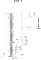
- Fig. 2 is a perspective view showing the outdoor heat exchanger 3.
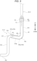
- Fig. 3 is an enlarged view of the refrigerant pipe 9 shown in Fig. 2 .
- the air-conditioner 100 includes an aluminum refrigerant pipe 91 and a copper refrigerant pipe 92.
- the aluminum refrigerant pipe 91 is made of aluminum or metal (aluminum alloy) containing aluminum.
- the copper refrigerant pipe 92 is made of copper or metal (copper alloy) containing copper.
- the configuration of the refrigerant pipe 9 includes the aluminum refrigerant pipe 91 and the copper refrigerant pipe 92.
- the aluminum refrigerant pipe 91 has a greater thickness than that of the copper refrigerant pipe 92.
- the air-conditioner 100 includes a connection portion 93 which connects the aluminum refrigerant pipe 91 (one end portion 911 thereof) and the copper refrigerant pipe 92 (one end portion 921 thereof).
- the aluminum refrigerant pipe 91 and the copper refrigerant pipe 92 are connected (joined), for example, by brazing, welding, or eutectic bonding.
- a connection portion between the aluminum refrigerant pipe 91 and the copper refrigerant pipe 92 is the connection portion 93.
- the one end portion 911 of the aluminum refrigerant pipe 91 is increased in diameter (see Fig. 3 ).
- the one end portion 921 of the copper refrigerant pipe 92 is fitted in the one end portion 911 of the aluminum refrigerant pipe 91.
- the one end portions 911, 921 are connected to each other by brazing. Since the one end portion 911 of the aluminum refrigerant pipe 91 is increased in diameter, the one end portion 911 avoids a brazing material from dripping from the connection portion 93.
- the aluminum refrigerant pipe 91 (except for the one end portion 911) has, before and after the connection portion 93, the substantially same outer diameter as that of the copper refrigerant pipe 92.
- the one end portion 911 of the aluminum refrigerant pipe 91 is located lower than the one end portion 921 of the copper refrigerant pipe 92.
- the aluminum refrigerant pipe 91 extends such that the one end portion 911 thereof faces up.
- the copper refrigerant pipe 92 extends such that the one end portion 921 thereof faces down.
- the one end portion 911 of the aluminum refrigerant pipe 91 and the one end portion 921 of the copper refrigerant pipe 92 extend in an up-down direction.
- connection portion 93 is located such that an angle between the center axis CL of the connection portion 93 and the up-down direction (vertical direction) is within 45 degrees. That is, the connection portion 93 is located so as to extend in the up-down direction. As described above, in the present embodiment, the center axis CL of the connection portion 93 is located coincident with the up-down direction. Note that the connection portion 93 may be located such that the center axis CL thereof is inclined with respect to the up-down direction.
- the center axis CL of the connection portion 93 is substantially coincident with the center axis of the one end portion 911 of the aluminum refrigerant pipe 91 and the center axis of the one end portion 921 of the copper refrigerant pipe 92.
- the aluminum refrigerant pipe 91 includes an inclined portion 913.
- the inclined portion 913 extends in a direction inclined upward with respect to the center axis CL of the connection portion 93 (see Fig. 2 ).
- a bottom portion 913b of the inclined portion 913 is located lower than the connection portion 93.
- one aluminum refrigerant pipe 91 may include a plurality of portions extending in the direction inclined upward with respect to the center axis CL of the connection portion 93. In this case, one of these portions having the shortest distance to the connection portion 93 along the aluminum refrigerant pipe 91 is the inclined portion 913.
- the air-conditioner 100 includes a cover 94 that covers the entire circumference of at least a portion of the refrigerant pipe 9 from the connection portion 93 to the bottom portion 913b of the inclined portion 913.
- a water droplet on the copper refrigerant pipe 92 flows down along the cover 94.
- the inclined portion 913 reduces the water droplet from reaching a portion of the aluminum refrigerant pipe 91 not covered with the cover 94.
- the inclined portion 913 does not occupy an internal space (unit internal space) of the outdoor unit 1 or the indoor unit 2 as compared to a conventional U-shaped or inverted U-shaped portion.
- the unit internal space can be ensured. Consequently, corrosion of the aluminum refrigerant pipe 91 is reduced.
- the unit internal space can be ensured.
- an angle ⁇ 1 between the direction of extension of the inclined portion 913 (a later-described linear portion 913a thereof) and the horizontal plane is preferably 10 degrees or more. This configuration can reduce the inclined portion 913 from facing horizontally or down even in a case where a floor on which the outdoor unit 1 (or the indoor unit 2) provided with the aluminum refrigerant pipe 91 is placed is inclined.
- the angle ⁇ 1 may be 15 degrees or more, 20 degrees or more, or 25 degrees or more.
- the angle ⁇ 1 is preferably 45 degrees or less. This configuration can reduce occupation of the unit internal space due to the inclined portion 913. More preferably, the angle ⁇ 1 is 35 degrees or less.
- the aluminum refrigerant pipe 91 includes a first curved portion 916 curved in a downwardly-raised shape and a second curved portion 917 curved in an upwardly-raised shape.
- the inclined portion 913 includes the linear portion 913a between the first curved portion 916 and the second curved portion 917.
- portions extending in the direction inclined upward with respect to the center axis CL of the connection portion 93 are included in the inclined portion 913.
- the inclined portion 913 includes the linear portion 913a, a bottom portion 916a of the first curved portion 916, and a top portion 917a of the second curved portion 917.
- the inclined portion 913 is shared by the first curved portion 916 or the second curved portion 917.
- the inclined portion 913 does not necessarily include the linear portion 913a, and may include the bottom portion 916a and the top portion 917a.
- the first curved portion 916 is located at a position lower than the second curved portion 917.
- the first curved portion 916 is located on the side closer to the one end portion 911 of the aluminum refrigerant pipe 91.
- the second curved portion 917 is located on the side closer to the other end portion 912 of the aluminum refrigerant pipe 91.
- the bottom portion 913b of the inclined portion 913 is the bottom portion 916a of the first curved portion 916.
- a top portion 913c of the inclined portion 913 is the top portion 917a of the second curved portion 917.
- the aluminum refrigerant pipe 91 includes one end linear portion 914 including the one end portion 911.
- the one end linear portion 914 extends linearly in the up-down direction, and is connected to the first curved portion 916.
- An angle ⁇ 2 between the direction of extension of the one end linear portion 914 and the direction of extension of the inclined portion 913 (the linear portion 913a thereof) is, for example, less than 90 degrees.
- the length of the linear portion 913a is less than the length of the one end linear portion 914 or the length of a later-described standing portion 915.
- the length of the linear portion 913a is set as necessary, for example, according to the outer diameter of the aluminum refrigerant pipe 91.
- the one end linear portion 914 is located substantially coincident with the up-down direction.
- the one end linear portion 914 may be located inclined with respect to the up-down direction.
- the entirety of the inclined portion 913 is located lower than the connection portion 93. Note that the present embodiment is not limited to this example. Part of the top portion 913c or linear portion 913a of the inclined portion 913 may be located higher than the connection portion 93.
- the cover 94 is made of a material having waterproof properties and capable of covering the refrigerant pipe 9 with no gap.
- the cover 94 is a heat-shrinkable tube curable after contracted by heating.
- the heat-shrinkable tube is made of, for example, polyolefin, fluorine-based polymer, or thermoplastic elastomer. Note that a coating film formed by painting the refrigerant pipe 9 may be used as a cover.
- the cover 94 covers at least the bottom portion 913b of the inclined portion 913. Preferably, the cover 94 covers the linear portion 913a. This configuration can further reduce the water droplet flowing down from the copper refrigerant pipe 92 from reaching the portion of the aluminum refrigerant pipe 91 not covered with the cover 94.
- the cover 94 may cover the top portion 913c of the inclined portion 913.
- the cover 94 preferably covers at least a portion from the one end portion 921 of the copper refrigerant pipe 92 to the bottom portion 913b of the inclined portion 913. This configuration can reduce the water droplet on the copper refrigerant pipe 92 from penetrating a gap between the cover 94 and the connection portion 93. As a result, corrosion of a portion of the aluminum refrigerant pipe 91 covered with the cover 94 can be reduced.
- the aluminum refrigerant pipe 91, the copper refrigerant pipe 92, and the connection portion 93 are located in the outdoor unit 1.
- the other end portion (not shown) of the copper refrigerant pipe 92 is connected to a refrigerant outlet/inlet (not shown) of the outdoor unit 1.
- the other end portion 912 of the aluminum refrigerant pipe 91 is connected to a refrigerant inlet 31 of the outdoor heat exchanger 3 serving as an evaporator.
- the refrigerant outlet/inlet of the outdoor unit 1 is preferably located higher than the refrigerant inlet 31 of the outdoor heat exchanger 3 serving as the evaporator.
- the refrigerant pipe 9 an increase in the total length of a liquid pipe, in which a two-phase flow is generated, of the refrigerant pipe 9 can be suppressed.
- the other end portion of the copper refrigerant pipe 92 is connected to the refrigerant outlet/inlet of the outdoor unit 1 through the expansion valve 4 (see Fig. 1 ).
- the other end portion 912 of the aluminum refrigerant pipe 91 is connected to the outdoor heat exchanger 3 through the expansion valve 4.
- the aluminum refrigerant pipe 91, the copper refrigerant pipe 92, and the connection portion 93 may be located in the indoor unit 2.
- the aluminum refrigerant pipe 91 preferably includes the standing portion 915 standing upward between the other end portion 912 and the second curved portion 917. According to such a configuration, a space can be provided in a lower portion in the outdoor unit 1 (or the indoor unit). Thus, for example, a pipe can pass through such a space.
- the standing portion 915 extends in the up-down direction.
- the standing portion 915 extends linearly in the up-down direction, and is connected to the second curved portion 917.
- the standing portion 915 is located substantially parallel with the one end linear portion 914.
- the aluminum refrigerant pipe 91 has a substantially Z-shape defined by the one end linear portion 914, the inclined portion 913, and the standing portion 915.
- the standing portion 915 is located such that the direction of extension thereof is substantially coincident with the up-down direction.
- the standing portion 915 is not limited to this example.
- the standing portion 915 may extend in a curved shape.
- the standing portion 915 may be located inclined with respect to the up-down direction.
- a stainless-steel refrigerant pipe made of stainless steel may be provided at the connection portion 93. That is, the aluminum refrigerant pipe 91 and the copper refrigerant pipe 92 may be connected to each other through the stainless-steel refrigerant pipe. According to such a configuration, the aluminum refrigerant pipe 91 and the copper refrigerant pipe 92 can be connected through the stainless-steel refrigerant pipe. Thus, corrosion of the aluminum refrigerant pipe 91 can be further reduced.
- the space can be provided in the lower portion in the outdoor unit 1 (or the indoor unit 2).
- the pipe can pass through such a space.
- the configuration of the air-conditioner 100 is not limited to the configuration of the embodiment above.
- the features and effects thereof are not limited to those described above.
- changes can be made to the air-conditioner 100 without departing from the gist of the present embodiment.
- one or more configurations or methods arbitrarily selected from the configurations or methods of the air-conditioners according to the embodiments described above as the modifications may be applied to the configuration or method of the air-conditioner according to the embodiment above, needless to say.
Landscapes
- Engineering & Computer Science (AREA)
- Mechanical Engineering (AREA)
- General Engineering & Computer Science (AREA)
- Physics & Mathematics (AREA)
- Thermal Sciences (AREA)
- Chemical & Material Sciences (AREA)
- Combustion & Propulsion (AREA)
- Heat-Exchange Devices With Radiators And Conduit Assemblies (AREA)
- Air Filters, Heat-Exchange Apparatuses, And Housings Of Air-Conditioning Units (AREA)
- Other Air-Conditioning Systems (AREA)
Applications Claiming Priority (1)
| Application Number | Priority Date | Filing Date | Title |
|---|---|---|---|
| JP2023207526A JP2025091957A (ja) | 2023-12-08 | 2023-12-08 | 空気調和機 |
Publications (1)
| Publication Number | Publication Date |
|---|---|
| EP4567352A1 true EP4567352A1 (de) | 2025-06-11 |
Family
ID=93590989
Family Applications (1)
| Application Number | Title | Priority Date | Filing Date |
|---|---|---|---|
| EP24213777.6A Withdrawn EP4567352A1 (de) | 2023-12-08 | 2024-11-19 | Klimaanlage |
Country Status (3)
| Country | Link |
|---|---|
| EP (1) | EP4567352A1 (de) |
| JP (1) | JP2025091957A (de) |
| CN (1) | CN120120651A (de) |
Citations (4)
| Publication number | Priority date | Publication date | Assignee | Title |
|---|---|---|---|---|
| US20130125578A1 (en) * | 2011-11-18 | 2013-05-23 | Juhyoung LEE | Air conditioner |
| WO2013084433A1 (ja) * | 2011-12-09 | 2013-06-13 | パナソニック株式会社 | 空気調和機の熱交換器 |
| JP2014159953A (ja) | 2014-04-28 | 2014-09-04 | Panasonic Corp | 冷凍サイクル装置 |
| JP2023051205A (ja) * | 2021-09-30 | 2023-04-11 | ダイキン工業株式会社 | 室内機および空気調和機 |
Family Cites Families (4)
| Publication number | Priority date | Publication date | Assignee | Title |
|---|---|---|---|---|
| JPH0332902Y2 (de) * | 1986-07-29 | 1991-07-12 | ||
| JP5881435B2 (ja) * | 2012-01-27 | 2016-03-09 | 三菱電機株式会社 | 熱交換器及びこれを備えた空気調和機 |
| US11415346B2 (en) * | 2020-04-30 | 2022-08-16 | Trane International Inc. | System and method for common side connections for oversized multislab microchannel heat exchanger |
| CN219932400U (zh) * | 2023-05-06 | 2023-10-31 | 海信(广东)空调有限公司 | 压缩机和空调器 |
-
2023
- 2023-12-08 JP JP2023207526A patent/JP2025091957A/ja active Pending
-
2024
- 2024-11-19 EP EP24213777.6A patent/EP4567352A1/de not_active Withdrawn
- 2024-11-21 CN CN202411675353.1A patent/CN120120651A/zh active Pending
Patent Citations (4)
| Publication number | Priority date | Publication date | Assignee | Title |
|---|---|---|---|---|
| US20130125578A1 (en) * | 2011-11-18 | 2013-05-23 | Juhyoung LEE | Air conditioner |
| WO2013084433A1 (ja) * | 2011-12-09 | 2013-06-13 | パナソニック株式会社 | 空気調和機の熱交換器 |
| JP2014159953A (ja) | 2014-04-28 | 2014-09-04 | Panasonic Corp | 冷凍サイクル装置 |
| JP2023051205A (ja) * | 2021-09-30 | 2023-04-11 | ダイキン工業株式会社 | 室内機および空気調和機 |
Also Published As
| Publication number | Publication date |
|---|---|
| CN120120651A (zh) | 2025-06-10 |
| JP2025091957A (ja) | 2025-06-19 |
Similar Documents
| Publication | Publication Date | Title |
|---|---|---|
| EP2620736B1 (de) | Wärmetauscher und Klimaanlagenvorrichtung damit | |
| CN105371539B (zh) | 空气调节器 | |
| JP7404213B2 (ja) | 冷凍装置、当該冷凍装置の冷媒配管、及び冷媒配管の製造方法 | |
| JP2023041799A (ja) | 冷凍装置及び当該冷凍装置の冷媒配管 | |
| US11698213B2 (en) | Heat exchanger, indoor unit for air-conditioner, and refrigeration device | |
| EP3748276A1 (de) | Wärmetauscher und klimaanlage | |
| CN104024747A (zh) | 制冷装置的室外单元 | |
| JP6318371B2 (ja) | 室外ユニットおよびそれを用いた冷凍サイクル装置 | |
| US20250224188A1 (en) | Component unit of air conditioning apparatus | |
| US6564575B1 (en) | Accumulator with inlet port comprising a deflector | |
| WO2023053553A1 (ja) | 室内機および空気調和機 | |
| US20180283703A1 (en) | Indoor unit for air conditioner | |
| JP2011027293A (ja) | 油分離器 | |
| WO2020070869A1 (ja) | 熱交換器及び冷凍サイクル装置 | |
| EP4283221A1 (de) | Wärmetauscher | |
| CN120120651A (zh) | 空调机 | |
| JP6020610B2 (ja) | 空気調和装置 | |
| JP7597510B2 (ja) | 熱交換器 | |
| JP7514591B2 (ja) | 冷凍システム用のコンパクト熱交換器アセンブリ | |
| CN115667819A (zh) | 压力容器及冷冻装置 | |
| WO2017130976A1 (ja) | 熱交換器、及びそれを備えた冷凍装置の室外ユニット | |
| JP6569700B2 (ja) | 冷凍装置の熱源ユニット | |
| WO2021234961A1 (ja) | 熱交換器、空気調和装置の室外機及び空気調和装置 | |
| JP7727878B1 (ja) | 空気調和機 | |
| US20240230112A1 (en) | Air conditioner indoor unit and air conditioner |
Legal Events
| Date | Code | Title | Description |
|---|---|---|---|
| PUAI | Public reference made under article 153(3) epc to a published international application that has entered the european phase |
Free format text: ORIGINAL CODE: 0009012 |
|
| STAA | Information on the status of an ep patent application or granted ep patent |
Free format text: STATUS: REQUEST FOR EXAMINATION WAS MADE |
|
| 17P | Request for examination filed |
Effective date: 20241220 |
|
| AK | Designated contracting states |
Kind code of ref document: A1 Designated state(s): AL AT BE BG CH CY CZ DE DK EE ES FI FR GB GR HR HU IE IS IT LI LT LU LV MC ME MK MT NL NO PL PT RO RS SE SI SK SM TR |
|
| STAA | Information on the status of an ep patent application or granted ep patent |
Free format text: STATUS: THE APPLICATION IS DEEMED TO BE WITHDRAWN |
|
| 18D | Application deemed to be withdrawn |
Effective date: 20251212 |