EP4567162A1 - Beschichtetes basismaterial - Google Patents
Beschichtetes basismaterial Download PDFInfo
- Publication number
- EP4567162A1 EP4567162A1 EP23849918.0A EP23849918A EP4567162A1 EP 4567162 A1 EP4567162 A1 EP 4567162A1 EP 23849918 A EP23849918 A EP 23849918A EP 4567162 A1 EP4567162 A1 EP 4567162A1
- Authority
- EP
- European Patent Office
- Prior art keywords
- film
- thickness
- region
- substrate
- atm
- Prior art date
- Legal status (The legal status is an assumption and is not a legal conclusion. Google has not performed a legal analysis and makes no representation as to the accuracy of the status listed.)
- Pending
Links
Images

Classifications
-
- C—CHEMISTRY; METALLURGY
- C23—COATING METALLIC MATERIAL; COATING MATERIAL WITH METALLIC MATERIAL; CHEMICAL SURFACE TREATMENT; DIFFUSION TREATMENT OF METALLIC MATERIAL; COATING BY VACUUM EVAPORATION, BY SPUTTERING, BY ION IMPLANTATION OR BY CHEMICAL VAPOUR DEPOSITION, IN GENERAL; INHIBITING CORROSION OF METALLIC MATERIAL OR INCRUSTATION IN GENERAL
- C23C—COATING METALLIC MATERIAL; COATING MATERIAL WITH METALLIC MATERIAL; SURFACE TREATMENT OF METALLIC MATERIAL BY DIFFUSION INTO THE SURFACE, BY CHEMICAL CONVERSION OR SUBSTITUTION; COATING BY VACUUM EVAPORATION, BY SPUTTERING, BY ION IMPLANTATION OR BY CHEMICAL VAPOUR DEPOSITION, IN GENERAL
- C23C30/00—Coating with metallic material characterised only by the composition of the metallic material, i.e. not characterised by the coating process
-
- C—CHEMISTRY; METALLURGY
- C25—ELECTROLYTIC OR ELECTROPHORETIC PROCESSES; APPARATUS THEREFOR
- C25D—PROCESSES FOR THE ELECTROLYTIC OR ELECTROPHORETIC PRODUCTION OF COATINGS; ELECTROFORMING; APPARATUS THEREFOR
- C25D9/00—Electrolytic coating other than with metals
- C25D9/04—Electrolytic coating other than with metals with inorganic materials
- C25D9/08—Electrolytic coating other than with metals with inorganic materials by cathodic processes
- C25D9/12—Electrolytic coating other than with metals with inorganic materials by cathodic processes on light metals
-
- C—CHEMISTRY; METALLURGY
- C23—COATING METALLIC MATERIAL; COATING MATERIAL WITH METALLIC MATERIAL; CHEMICAL SURFACE TREATMENT; DIFFUSION TREATMENT OF METALLIC MATERIAL; COATING BY VACUUM EVAPORATION, BY SPUTTERING, BY ION IMPLANTATION OR BY CHEMICAL VAPOUR DEPOSITION, IN GENERAL; INHIBITING CORROSION OF METALLIC MATERIAL OR INCRUSTATION IN GENERAL
- C23C—COATING METALLIC MATERIAL; COATING MATERIAL WITH METALLIC MATERIAL; SURFACE TREATMENT OF METALLIC MATERIAL BY DIFFUSION INTO THE SURFACE, BY CHEMICAL CONVERSION OR SUBSTITUTION; COATING BY VACUUM EVAPORATION, BY SPUTTERING, BY ION IMPLANTATION OR BY CHEMICAL VAPOUR DEPOSITION, IN GENERAL
- C23C26/00—Coating not provided for in groups C23C2/00 - C23C24/00
-
- C—CHEMISTRY; METALLURGY
- C25—ELECTROLYTIC OR ELECTROPHORETIC PROCESSES; APPARATUS THEREFOR
- C25D—PROCESSES FOR THE ELECTROLYTIC OR ELECTROPHORETIC PRODUCTION OF COATINGS; ELECTROFORMING; APPARATUS THEREFOR
- C25D9/00—Electrolytic coating other than with metals
- C25D9/04—Electrolytic coating other than with metals with inorganic materials
- C25D9/08—Electrolytic coating other than with metals with inorganic materials by cathodic processes
- C25D9/10—Electrolytic coating other than with metals with inorganic materials by cathodic processes on iron or steel
Definitions
- the present disclosure relates to a coated substrate.
- Patent Literatures 1 to 4 disclose coated substrates having metal oxide films.
- a wet film-formation method is employed.
- a dry film-formation method has been employed so as to perform thickness control in accordance with complex substrate shapes.
- the present disclosure was made in view of the above-described circumstances, and an object is to provide a novel coated substrate which can be applied to various fields and can be mass produced.
- the present disclosure can be realized as the following modes.
- a coated substrate 1 includes a substrate 5 coated with a film 3.
- the thickness T of the film 3 is 1 nm or greater and less than 800 nm.
- X-ray photoelectron spectroscopic measurement of the film 3 shows that the total percent element composition of a metal element and O (oxygen) is 70 atm% or greater.
- the relative density of the film 3 is 90% or greater.
- the coated substrate 1 satisfies at least one of the following conditions (1) and (2).
- the functionality of the coated substrate 1 is enhanced as a result of satisfaction of at least one of the conditions (1) and (2).
- Condition (1) the maximum thickness T1max of the film 3 formed on an edge region S1 of a surface S of the substrate 5 is greater than the thickness T2 of the film 3 formed on an inner region S2 of the surface S located inward of the edge region S1.
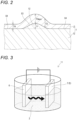
- Condition (2) the maximum thickness T3max of the film 3 formed on a convex portion present region S3 of the surface S of the substrate 5 is greater than the thickness T4 of the film 3 formed on a convex portion absent region S4 of the surface S.
- FIG. 1 shows a schematic view of a cross section of one example of the coated substrate 1.
- FIG. 1 shows an example in which the film 3 is formed on one side of the substrate 5, the film 3 may be formed on opposite sides of the substrate 5.
- FIG. 2 shows a schematic view of a cross section of another example of the coated substrate 1.
- FIG. 2 shows an example in which the film 3 is formed on one side of the substrate 5, the film 3 may be formed on opposite sides of the substrate 5.
- the substrate 5 is preferably formed of a material which is electrically conductive and can function as a negative electrode 7 (cathode).
- the film 3 can be easily formed on that portion by a manufacturing method described below.
- a surface portion of the substrate 5 may be formed of a material which is electrically conductive and can function as the negative electrode 7.
- the entire substrate 5 may be formed of a material which can function as the negative electrode 7.
- preferred materials which can serve as the negative electrode 7 include an iron-based alloy and carbon.
- An example of preferred iron-based alloys is one or more types of alloys selected from Fe-Ni-Cr alloy (stainless steel), Fe-Ni alloy (permalloy), Fe-Si alloy (silicon iron), Fe-Si-Al alloy (Sendust), Fe-Ni-Mo (supermalloy), Fe-Co alloy (permendur), and Fe-C-B alloy (amorphous).
- the thickness T of the film 3 is the shortest distance from a point on the surface of the film 3 to the surface S of the substrate 5. From the viewpoint of enabling the film 3 to exhibit a function corresponding to the material of the film 3, the thickness T of the film 3 is 1 nm or greater, preferably 10 nm or greater, more preferably 50 nm or greater. Meanwhile, from the viewpoint of enabling the film 3 to endure stresses generated therein and securing adhesion to the substrate 5, the thickness T of the film 3 is less than 800 nm, preferably 500 nm or less, more preferably 200 nm or less.
- the thickness T of the film 3 is 1 nm or greater and less than 800 nm, preferably 10 nm or greater and 500 nm or less, more preferably 50 nm or greater and 200 nm or less.
- the film 3 satisfies the requirement regarding the thickness T when the thickness T of at least a portion of the film 3 falls within the above-described range.
- the thickness of the film 3 can be obtained through observation under an FIB-SEM.
- the condition (1) is such that the maximum thickness T1max of the film 3 formed on the edge region S1 of the surface S of the substrate 5 is greater than the thickness T2 of the film 3 formed on the inner region S2 of the surface S located inward of the edge region S1.
- the maximum thickness T1max of the film 3 formed on the edge region S1 is the maximum value of the thickness T1 of the film 3 formed on the edge region S1.
- the edge region S1 is, for example, a region which is located, in a cross sectional view, within a circular region whose center is located an end portion SE of the surface S of the substrate 5 and whose radius is 5 mm.
- the edge region S1 is a region surrounded by a dash-dot line.
- the maximum thickness T1max is the thickness T1 at the end portion SE.
- the maximum thickness T1max is, for example, preferably 10 nm or greater and 1000 nm or less, more preferably 50 nm or greater and 800 nm or less, further preferably 100 nm or greater and 500 nm or less.
- the thickness T2 is, for example, preferably 1 nm or greater and 800 nm or less, more preferably 10 nm or greater and 500 nm or less, further preferably 50 nm or greater and 200 nm or less.
- the maximum thickness T1max of the film 3 formed on the edge region S1 is preferably greater than the thickness T2 of the film 3 formed on the inner region S2 by 10% or more of the thickness T2, more preferably greater than the thickness T2 by 20% or more of the thickness T2, and further preferably greater than the thickness T2 by 30% or more of the thickness T2.
- the thickness T2 is not uniform, if the the maximum thickness T1max is greater than the thickness T2 in at least a portion of the inner region S2 by a certain percentage or more of the thickness T2, the above-described relation is satisfied.
- the maximum thickness T1max is equal to or less than 400% of the thickness T2.
- condition (1) it is preferred that the thickness T of the film 3 decreases toward the inner region S2 from a position where the film 3 formed on the edge region S1 has the maximum thickness T1max.
- irregularities whose sizes are equal to or less than 10% of the maximum thickness T1max are not taken into consideration.
- determination as to whether or not the condition (1) regarding the thickness T of the film 3 is satisfied is made by observing, under an FIB-SEM, a cross section of the coated substrate 1 which extends perpendicularly to the surface S of the substrate 5.
- the condition (2) is such that the maximum thickness T3max of the film 3 formed on the convex portion present region S3 of the surface S of the substrate 5 is greater than the thickness T4 of the film 3 formed on the convex portion absent region S4 of the surface S.
- the maximum thickness T3max of the film 3 formed on the convex portion present region S3 is the maximum value of the thickness T3 of the film 3 formed on the convex portion present region S3. No particular limitation is imposed on the shape, size, number of a convex portion(s) 12.
- the condition (2) regarding the thickness T of the film 3 is satisfied if the condition (2) is satisfied in a combination of the film 3 formed on the convex portion present region S3 associated with one convex portion 12 and the film 3 formed on the convex portion absent region S4 located adjacent thereto.
- the convex portion 12 may have, for example, a mount-like shape, a protruding shape, a needle-like shape, or a columnar shape.
- the maximum height h of the convex portion 12 is, for example, preferably 100 nm or greater and 10 mm or less, more preferably 500 nm or greater and 5 mm or less, further preferably 1000 nm or greater and 2 mm or less.
- the maximum height h of the convex portion 12 means the height from the surface S of the substrate 5 in the convex portion absent region S4, which surface severs as a reference.
- the occupation area of the convex portion 12 is, for example, preferably 10 ⁇ m 2 or greater and 100 mm 2 or less, more preferably 100 ⁇ m 2 or greater and 10 mm 2 or less, further preferably 500 ⁇ m 2 or greater and 1 mm 2 or less.
- the maximum thickness T3max is, for example, preferably 10 nm or greater and 1000 nm or less, more preferably 50 nm or greater and 800 nm or less, further preferably 100 nm or greater and 500 nm or less.
- the thickness T4 is, for example, preferably 1 nm or greater and 800 nm or less, more preferably 10 nm or greater and 500 nm or less, further preferably 50 nm or greater and 200 nm or less.
- the maximum thickness T3max of the film 3 formed on the convex portion present region S3 is preferably greater than the thickness T4 of the film 3 formed on the convex portion absent region S4 by 10% or more of the thickness T4, more preferably greater than the thickness T4 by 20% or more of the thickness T4, and further preferably greater than the thickness T4 by 30% or more of the thickness T4.
- the thickness T4 is not uniform, if the the maximum thickness T3max is greater than the thickness T4 in at least a portion of the convex portion absent region S4 by a certain percentage or more of the thickness T4, the above-described relation is satisfied.
- the maximum thickness T3max is equal to or less than 400% of the thickness T4.
- condition (2) it is preferred that the thickness T of the film 3 decreases toward the convex portion absent region S4 from a position where the film 3 formed on the convex portion present region S3 has the maximum thickness T3max.
- irregularities whose sizes are equal to or less than 10% of the maximum thickness T3max are not taken into consideration.
- determination as to whether or not the condition (2) regarding the thickness T of the film 3 is satisfied is made by observing, under an FIB-SEM, a cross section of the coated substrate 1 which extends perpendicularly to the surface S of the substrate 5.
- the percent element composition of C (carbon) determined through measurement by x-ray photoelectron spectroscopy (XPS method) is 0.1 atm% or greater, preferably 0.5 atm% or greater, more preferably 1 atm% or greater. Meanwhile, from the viewpoint of enabling the film 3 to sufficiently function as an inorganic film, the percent element composition of C (carbon) is less than 20 atm%, preferably 15 atm% or less, more preferably 10 atm% or less.
- the percent element composition of C (carbon) is 0.1 atm% or greater and less than 20 atm%, preferably 0.5 atm% or greater and 15 atm% or less, more preferably 1 atm% or greater and 10 atm% or less.
- the film 3 satisfies the requirement regarding the percent element composition of C (carbon) when the composition of at least a portion of the film 3 falls within the above-described range.
- the composition analysis by the x-ray photoelectron spectroscopy can be performed by using an x-ray photoelectron spectrometer.
- the measurement can be performed by scanning a cross section under the following measurement conditions: K-alpha rays of aluminum being used as an x-ray source, the beam diameter being set to 100 ⁇ m, and the x-ray incident angle in relation to a surface to be analyzed being set to 45°.
- the total percent element composition of the metal element and O (oxygen) of the film 3 determined through measurement by the x-ray photoelectron spectroscopy (XPS method) is 70 atm% or greater, preferably 80 atm% or greater, more preferably 90 atm% or greater.
- the upper limit of the total percent element composition of the metal element and O (oxygen) is a value obtained by subtracting the percent element composition (atm%) of C (carbon) from 100 atm%. In the case where the composition of the film 3 is not uniform, the film 3 satisfies the requirement regarding the total percent element composition of the metal element and O (oxygen) when the composition of at least a portion of the film 3 falls within the above-described range.
- the relative density of the film 3 is 90% or greater, preferably 95% or greater, more preferably 98% or greater.
- the relative density of the film 3 may be 100%.
- the relative density of the film 3 is obtained by the following method.
- a TEM image of a cross section of the film 3 obtained by cutting the film 3 in the film-thickness direction is obtained.
- the area of pores in a field of view of 300 nm (vertical dimension) ⁇ 1000 nm (horizontal dimension) is measured.
- the relative density (%) is obtained in accordance with the following expression (1).
- the average of the relative densities of 10 fields of view is the relative density of the film 3.
- measurement is performed in fields of view determined in accordance with the thickness of the film 3.
- Relative density % S 1 ⁇ S 2 / S 1 ⁇ 100 (In the expression, S1 is the area (nm 2 ) of the field of view of 300 nm (vertical dimension) ⁇ 1000 nm (horizontal dimension), and S2 is the total area (nm 2 ) of pores in the field of view of 300 nm (vertical dimension) ⁇ 1000 nm (horizontal dimension))
- the film 3 is amorphous.
- the fact that the film 3 is amorphous can be confirmed by using a TEM image.
- crystal grains do not come off and peculiar functions (such as smoothing the outermost surface by uniform film growth) are exhibited.
- the percent element composition of the halogen element as determined through measurement of the film 3 by x-ray photoelectron spectroscopy is preferably 0.1 atm% or greater, more preferably 0.3 atm% or greater, further preferably 0.5 atm% or greater.
- the upper limit value of the percent element composition of the halogen element is 3 atm% or less.
- the oxide film present on the surface of the substrate 5 is removed by the action of the halogen element, and the film 3 comes into direct contact with the substrate 5. As a result, the adhesion between the substrate 5 and the film 3 is secured.
- the metal element is preferably at least one or more metal elements selected from the group consisting of Al (aluminum), Ti (titanium), Mo (molybdenum), Cr (chromium), Mn (manganese), Fe (iron), Co (cobalt), Ni (nickel), Zr (zirconium), V (vanadium), W (tungsten), Ta (tantalum), Nb (niobium), and Sn (tin).
- the preferred manufacturing method is a method for manufacturing the coated substrate 1 by using a bath liquid 2 containing an organic solvent.
- the water content of the bath liquid 2 is less than 1 mass% and the bath liquid 2 contains at least one or more types of metal elements and at least one or more types of halogen elements.
- the film 3 is formed on the substrate 5, which serves as a negative electrode 7 (cathode).
- electrodeposition is taken place on the negative electrode 7 side, oxidation of the substrate 5 can be suppressed as compared with the case where electrodeposition is taken place on the positive electrode 6 side (anode side).
- the bath liquid 2 contains an organic solvent.
- the water content of the bath liquid 2 is rendered less than 1 mass%.
- the water content is preferably less than 0.5 mass%, more preferably less than 0.1 mass%.
- the water content may be 0 mass%.
- the water content of the bath liquid 2 can be obtained by GC-MS analysis.
- the bath liquid 2 contains at least one or more types of metal elements. No particular limitation is imposed on the metal elements. From the viewpoint of causing the film 3 to function as a high quality protection film for the substrate 5, the metal element is preferably at least one or more metal elements selected from the group consisting of Al (aluminum), Ti (titanium), Mo (molybdenum), Cr (chromium), Mn (manganese), Fe (iron), Co (cobalt), Ni (nickel), Zr (zirconium), V (vanadium), W (tungsten), Ta (tantalum), Nb (niobium), and Sn (tin). In the manufacturing method of the present disclosure, an oxide film depending on the metal element(s) in the bath liquid 2 is formed as the film 3.
- the metal element(s) contained in the bath liquid 2 may be supplied as a result of elution of the positive electrode 6 (anode).
- the metal element(s) elutes from the positive electrode 6 into the bath liquid 2
- control of film formation speed becomes easy, and continuous and stable formation of films on a plurality of substrates 5 becomes possible.
- the metal element(s) is supplied to the bath liquid 2 as a result of elution of the positive electrode 6, at least one or more types of electrodes selected from an electrode of Al, an electrode of Ti, and an electrode of Mo are preferably used as the positive electrode 6.
- the metal element(s) in the bath liquid 2 may be supplied from a metal alkoxide and/or an inorganic metal compound.
- the metal element(s) is supplied as a result of dissolution of a metal alkoxide and/or an inorganic metal compound, it is possible to cope with an element which is difficult to supply by eluting the positive electrode 6 (anode). Also, in this case, it becomes possible to perform film formation in which composition ratios are controlled by combining a plurality of metal elements.
- metal alkoxide examples include an aluminum alkoxide, a titanium alkoxide, and a molybdenum alkoxide.
- Examples of the aluminum alkoxide include an aluminum trialkoxide.
- Examples of the aluminum trialkoxide include aluminum tripropoxides (e.g., aluminum triisopropoxide and aluminum tri-n-propoxide), aluminum triethoxide, aluminum tributoxides (e.g., aluminum tri-sec-butoxide and aluminum tri-n-butoxide).
- titanium alkoxide examples include a titanium trialkoxide, a titanium tetraalkoxide, and a titanium tetraalkoxide is preferred.
- titanium tetraalkoxide examples include titanium tetrapropoxides (e.g., titanium tetraisopropoxide and titanium tetra-n-propoxide), titanium tetramethoxide, titanium tetraethoxide, titanium tetrabutoxides (e.g., titanium tetraisobutoxide and titanium tetra-n-butoxide), titanium tetrapentoxides, titanium tetrahexoxides, and titanium tetra (2-ethylhexoxide).
- titanium tetrapropoxides e.g., titanium tetraisopropoxide and titanium tetra-n-propoxide
- titanium tetramethoxide titanium tetraethoxide
- Examples of the inorganic metal compound include aluminum chloride, aluminum bromide, aluminum iodide, and titanium iodide.
- the metal element concentration of the bath liquid 2 is preferably 1 ppm or greater and 100 ppm or less, more preferably 3 ppm or greater and 10 ppm or less, further preferably 4 ppm or greater and 6 ppm or less.
- ppm means "parts per million” and "mg/L.”
- the above-described metal element concentration means the total concentration with respect to the plurality of metal elements.
- the metal element concentration of the bath liquid 2 can be measured by ICP-MS analysis.
- the bath liquid 2 contains at least one or more types of halogen elements. Since the bath liquid 2 contains a halogen element(s), film formation is performed at a practical speed, and the film 3 is likely to become homogeneous. No particular limitation is imposed on the halogen element. From the viewpoint of enabling prompt progress of organic electrochemical reactions and causing the film 3 to function as a high quality protection film for the substrate 5, the halogen element(s) is preferably at least one or more halogen elements selected from the group consisting of Cl (chlorine), Br (bromine), and I (iodine).
- the halogen element concentration of the bath liquid 2 is preferably 1 ppm or greater and 20000 ppm or less, more preferably 5 ppm or greater and 2000 ppm or less, further preferably 10 ppm or greater and 100 ppm or less.
- ppm means "parts per million” and "mg/L.”
- the halogen element concentration of the bath liquid 2 can be obtained from the amount of a halogen element(s) added at the time of making-up of the electrolytic bath or by ICP-MS analysis.
- the solvent preferably contains at least one or more types of solvents selected from the group consisting of ketones and nitriles.
- the solvent contains a ketone and/or a nitrile, it is supposed that a condensation reaction occurs on the electrode surface (cathode surface) and electrodeposition becomes possible.
- the solvent contains a ketone, conceivably, ketoenol tautomerism occurs in the presence of halogen, and the reactivity of the bath liquid 2 is enhanced.
- ketone examples include acetone, methyl ethyl ketone (MEK), 1-hexanone, 2-hexanone, 4-heptanone, 2-heptanone (methyl amyl ketone), 1-octanone, 2-octanone, 1-nonanone, 2-nonanone, diisobutyl ketone, methyl isobutyl ketone, acetylacetone, acetonylacetone, phenylacetone, acetophenone, methyl naphthyl ketone, cyclohexanone (CHN), and methylcyclohexanone.
- acetone and methyl ethyl ketone are preferred, because the film 3 is formed particularly satisfactorily.
- Nitrile is an organic solvent which contains a nitrile group (-CN) in its structure.
- nitrile include acetonitrile, propionitrile, valeronitrile, and butyronitrile. Among these, acetonitrile is preferred, because the film 3 is formed particularly satisfactorily.
- a film 3 is formed on the substrate 5, which serves as the negative electrode 7.
- the positive electrode 6 and the negative electrode 7 are immersed into the bath liquid 2, and a potential gradient is generated between the two electrodes.
- any of known electrically conductive substrates may be used as the positive electrode 6.
- the metal element(s) in the bath liquid 2 is supplied as a result of elution of the positive electrode 6, at least one or more types of electrodes selected from an electrode of Al, an electrode of Ti, and an electrode of Mo are preferably used as the positive electrode 6.
- the positive electrode 6 may be foil like, plate like, foam like, nonwoven fabric like, mesh like, felt like, or expanded metal like.
- the positive electrode 6 and the negative electrode 7 are preferably disposed to face each other.
- the positive electrode 6 and the negative electrode 7 are connected to a DC power supply, which can generate a potential gradient between the positive electrode 6 and the negative electrode 7.
- a voltage for example, constant voltage
- the power supply connected to the positive electrode 6 and the negative electrode 7.
- the potential gradient generated between the two electrodes is preferably 10 V or higher and 300 V or lower, more preferably 20 V or higher and 100 V or lower, further preferably 60 V or higher and 80 V or lower.
- the application time is, for example, preferably 10 seconds or longer and 300 seconds or shorter, more preferably 30 seconds or longer and 240 seconds or shorter, further preferably 60 seconds or longer and 180 seconds or shorter.
- the voltage is not required to be a constant voltage and the magnitude of the voltage may be changed.
- the amount of carbon in the film 3 may be reduced by means of heat treatment and/or light irradiation.
- the amount of carbon in the film 3 by means of heat treatment and/or light irradiation, it is possible to control the purity of the film 3 as an inorganic oxide film.
- the treatment temperature of the heat treatment is preferably 100°C or higher and 1000°C or lower, more preferably 300°C or higher and 800°C or lower, further preferably 500°C or higher and 600°C or lower.
- the treatment time of the heat treatment is preferably 1 minute or longer and 60 minutes or shorter, more preferably 5 minutes or longer and 45 minutes or shorter, further preferably 10 minutes or longer and 30 minutes or shorter.
- the wavelength of light used for light irradiation is preferably 250 nm or longer and 1100 nm or shorter, more preferably 300 nm or longer and 800 nm or shorter, further preferably 400 nm or longer and 500 nm or shorter.
- the light irradiation time is preferably 3 seconds or longer and 120 seconds or shorter, more preferably 5 seconds or longer and 60 seconds or shorter, further preferably 10 seconds or longer and 30 seconds or shorter.
- the coated substrate 1 of the present embodiment is excellent in functionality and/or durability, because the films 3 on the edge region S1 and the convex portion present region S3, which are likely to come into contact, in particular, with a surrounding environment when the coated substrate 1 is used, are selectively formed to be thicker.
- the novel coated substrate 1 which can be applied to various fields and can be mass produced.
- the coated substrate 1 of the present embodiment can be formed without use of an expensive material or by using only a small amount of an expensive material. Therefore, the coated substrate 1 is advantageous in terms of cost.
- the coated substrate 1 of the present embodiment since post treatments, such as heat treatment and light irradiation, are not necessarily needed for formation of the film 3, it is possible to expand the choices of the material and shape of the substrate 5.
- measurement conditions of XPS x-ray photoelectron spectroscopy
- Example 1 (solvent: MEK, positive electrode 6: aluminum)
- the film formation apparatus 11 shown in FIG. 3 was used.
- An aluminum wire was used as the positive electrode 6.
- a stainless plate was used as the negative electrode 7.
- the negative electrode 7 is a substrate 5 on which a film 3 is to be formed.
- Methyl ethyl ketone (MEK) was used as the solvent of the bath liquid 2.
- Iodine (halogen) was dissolved in the bath liquid 2 at a concentration of 600 ppm.
- the percent element composition of carbon in the film 3 was 5.8 atm%, and the total percent element composition of aluminum and oxygen was 93.9 atm%.
- the percent element composition of iodine in this film 3 was less than 0.1 atm% (lower measurement limit).
- the relative density of the film 3 determined by the following method was 100%.
- the relative density of the film 3 was determined as follows. A TEM image was obtained from a cross section of the film 3 obtained by cutting the film 3 in the film-thickness direction. The area of pores was measured in a field of view of 300 nm (vertical dimension) ⁇ 1000 nm (horizontal dimension). The relative density (%) was obtained in accordance with the following expression (1). The average of the relative densities of 10 fields of view is the relative density of the film 3. Notably, in the case where the thickness of the film 3 is smaller than the vertical size of 300 nm, measurement is performed in fields of view determined in accordance with the thickness of the film 3.
- Relative density % S 1 ⁇ S 2 / S 1 ⁇ 100 (In the expression, S1 is the area (nm 2 ) of the field of view of 300 nm (vertical dimension) ⁇ 1000 nm (horizontal dimension), and S2 is the total area (nm 2 ) of pores in the field of view of 300 nm (vertical dimension) ⁇ 1000 nm (horizontal dimension))
- the percent element composition of carbon in the film 3 was 6.5 atm%, and the total percent element composition of aluminum and oxygen was 93.3 atm%.
- the percent element composition of iodine in this film 3 was 0.1 atm%.
- the relative density of the film 3 determined by the above-described method was 100%.
- a titanium wire was used as the positive electrode 6.
- An experiment was carried out under the same conditions as Example 1, except for the above described point.
- Observation of a cross section of the negative electrode 7 under the FIB-SEM revealed that a film 3 of 90 nm was formed on the surface of the substrate 5.
- Analysis by means of XPS revealed that the film 3 is titanium oxide.
- the percent element composition of carbon in the film 3 was 24.6 atm%, and the total percent element composition of titanium and oxygen was 78.7 atm%.
- the percent element composition of iodine in this film 3 was 0.3 atm%.
- the relative density of the film 3 determined by the above-described method was 100%.
- the percent element composition of carbon in the film 3 was 9.2 atm%, and the total percent element composition of titanium and oxygen was 83.7 atm%.
- the percent element composition of iodine in this film 3 was 0.4 atm%.
- the relative density of the film 3 determined by the above-described method was 100%.
- a molybdenum wire was used as the positive electrode 6.
- An experiment was carried out under the same conditions as Example 1, except for the above described point.
- Observation of a cross section of the negative electrode 7 under the FIB-SEM revealed that a film 3 of 160 nm was formed on the surface of the substrate 5.
- Analysis by means of XPS revealed that the film 3 is molybdenum oxide.
- the percent element composition of carbon in the film 3 was 14.8 atm%, and the total percent element composition of molybdenum and oxygen was 78.7 atm%.
- the percent element composition of iodine in this film 3 was less than 0.1 atm% (detection limit or lower).
- the relative density of the film 3 determined by the above-described method was 100%.
- the percent element composition of carbon in the film 3 was 12.7 atm%, and the total percent element composition of molybdenum and oxygen was 78.0 atm%.
- the percent element composition of iodine in this film 3 was less than 0.1 atm% (detection limit or lower).
- the relative density of the film 3 determined by the above-described method was 100%.
- Acetonitrile was used as the solvent of the bath liquid 2.
- Iodine (halogen) was dissolved in the bath liquid 2 at a concentration of 2400 ppm.
- An experiment was carried out under the same conditions as Example 1, except for the above described points.
- Observation of a cross section of the negative electrode 7 under the FIB-SEM revealed that a film 3 of 140 nm was formed on the surface of the substrate 5.
- Analysis by means of XPS revealed that the film 3 is aluminum oxide. Oxygen which was not present in the bath liquid 2 was present in the film 3. It is supposed that oxygen was originated from water contained in the bath liquid 2 or moisture absorbed from the atmosphere.
- the percent element composition of carbon in the film 3 was 9.8 atm%, and the total percent element composition of aluminum and oxygen was 90.1 atm%.
- the percent element composition of iodine in this film 3 was 0.1 atm%.
- the relative density of the film 3 determined by the above-described method was 100%.
- the maximum thickness T1max of the film 3 formed on the edge region 1 was greater than the thickness T2 of the film 3 formed on the inner region S2 by 10% or more of the thickness T2.
- the thickness T of the film 3 decreased toward the inner region S2 from a position where the film 3 formed on the edge region S1 had the maximum thickness T1max.
- Example 8 (solvent: acetone, metal alkoxide: aluminum triisopropoxide)
- the film formation apparatus 11 shown in FIG. 3 was used.
- a carbon electrode was used as the positive electrode 6.
- a stainless plate was used as the negative electrode 7.
- the negative electrode 7 is a substrate 5 forming a film 3 on the surface S.
- Acetone was used as the solvent of the bath liquid 2.
- Aluminum triisopropoxide was dissolved in the bath liquid 2 at a concentration of 16 mg/L (16 ppm), and iodine (halogen) was dissolved in the bath liquid 2 at a concentration of 2400 mg/L (2400 ppm).
- the percent element composition of carbon in the film 3 was 8.4 atm%, and the total percent element composition of aluminum and oxygen was 84.3 atm%.
- the percent element composition of iodine in this film 3 was less than 0.1 atm% (detection limit or lower).
- the relative density of the film 3 determined by the above-described method was 100%.
- Methyl ethyl ketone was used as the solvent of the bath liquid 2.
- An experiment was carried out under the same conditions as Example 8, except for the above described point.
- Observation of a cross section of the negative electrode 7 under the FIB-SEM revealed that a film 3 was formed on the surface S of the substrate 5.
- Analysis by means of XPS revealed that the film 3 is aluminum oxide.
- the percent element composition of carbon in the film 3 was 8.6 atm%, and the total percent element composition of aluminum and oxygen was 83.6 atm%.
- the percent element composition of iodine in this film 3 was less than 0.1 atm% (detection limit or lower).
- the relative density of the film 3 determined by the above-described method was 100%.
- the percent element composition of carbon in the film 3 was 8.8 atm%, and the total percent element composition of titanium and oxygen was 86.1 atm%.
- the percent element composition of iodine in this film 3 was 1.3 atm%.
- the relative density of the film 3 determined by the above-described method was 100%.
- the percent element composition of carbon in the film 3 was 9.5 atm%, and the total percent element composition of titanium and oxygen was 85.9 atm%.
- the percent element composition of iodine in this film 3 was 0.9 atm%.
- the relative density of the film 3 determined by the above-described method was 100%.
- the maximum thickness T1max of the film 3 formed on the edge region S1 was greater than the thickness T2 of the film 3 formed on the inner region S2 by 10% or more of the thickness T2.
- the thickness T of the film 3 decreased toward the inner region S2 from a position where the film 3 formed on the edge region S1 had the maximum thickness T1max.
- the films 3 formed in Examples 1, 2, 3, and 7 were analyzed by FT-IR.
- the measurement conditions are as follows.
- the film formation apparatus 11 shown in FIG. 1 was used.
- An aluminum wire was used as the positive electrode 6.
- a stainless plate was used as the negative electrode 7.
- the negative electrode 7 serves as a substrate 5 forming a film 3 on the surface S.
- Various types of solvents such as acetone, methyl ethyl ketone (MEK), methyl isobutyl ketone, and diisobutyl ketone were used as solvents of bath liquids 2.
- Iodine (halogen) was dissolved in each bath liquid 2 at a concentration of 2100 mg/L (2100 ppm).
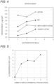
- the graph of FIG. 4 shows the relation between application time (electrodeposition time) and deposition weight (deposition mass) for cases where the respective solvents were used.
- the deposition weight is the weight of the formed film.
- a first sample (coated substrate 1) was produced in the same manner as in Example 1. After having pulled out the first sample from the bath liquid 2, a new stainless plate was immersed into the bath liquid 2, and a voltage was applied in the same manner as in Example 1, thereby producing a second sample. In the same manner, third and fourth samples were produced. When each sample was pulled out from the bath liquid 2, a portion of the bath liquid 2 was sampled, and the aluminum element concentration was measured by ICP-MS.
- the graph of FIG. 5 shows the relation between the number of samples experimentally produced and the aluminum element concentration of the bath liquid 2. It was found from the graph of FIG. 5 that the aluminum element concentration tends to increase with the number of samples experimentally produced. In the fourth sample, the film 3 tended to separate from the substrate 5. Therefore, it was found that, for continuous production of samples, the aluminum element concentration is preferably 1 ppm or greater and 6 ppm or less.
- the film formation apparatus 11 shown in FIG. 3 was used.
- An aluminum wire was used as the positive electrode 6.
- a stainless plate was used as the negative electrode 7.
- the negative electrode 7 serves as a substrate 5 forming a film 3 on the surface S.
- Various types of solvents i.e., acetone and methyl ethyl ketone (MEK)
- MEK methyl ethyl ketone
- Iodine (halogen) was dissolved in the bath liquids 2 in amounts shown Table 1.
- Table 1 Solvent Amount of iodine (g/L) Film formation state First sample Second sample Third sample Fourth sample Fiftieth sample Acetone 0.014 A A A A A 0.14 A A B B - 0.6 A B B B - 1.2 A A B B - 2.4 A A A B - MEK 0.014 A A A A A 0.6 A A A B - 1.2 A A A B - 2.4 A B B B -
- Formation of the film 3 was attempted for cases where various types of substrates 5 were use.
- a permalloy plate, a titanium plate, a copper plate, and a carbon plate were used, respectively. Experiments were carried out under the same conditions as in Example 1 except for the above-described point.
- the film 3 was stably formed on each of the substrates 5. Therefore, it was confirmed that stable formation of the film 3 is possible irrespective of the type of the substrate 5.
- novel coated substrates 1 which can be applied to various fields and can be mass-produced are provided.
Landscapes
- Chemical & Material Sciences (AREA)
- Metallurgy (AREA)
- Engineering & Computer Science (AREA)
- Chemical Kinetics & Catalysis (AREA)
- Materials Engineering (AREA)
- Organic Chemistry (AREA)
- Electrochemistry (AREA)
- Inorganic Chemistry (AREA)
- Mechanical Engineering (AREA)
- Cell Electrode Carriers And Collectors (AREA)
- Laminated Bodies (AREA)
- Chemical Vapour Deposition (AREA)
- Carbon And Carbon Compounds (AREA)
Applications Claiming Priority (2)
| Application Number | Priority Date | Filing Date | Title |
|---|---|---|---|
| JP2022125323 | 2022-08-05 | ||
| PCT/JP2023/026615 WO2024029363A1 (ja) | 2022-08-05 | 2023-07-20 | 被覆基材 |
Publications (1)
| Publication Number | Publication Date |
|---|---|
| EP4567162A1 true EP4567162A1 (de) | 2025-06-11 |
Family
ID=89848926
Family Applications (1)
| Application Number | Title | Priority Date | Filing Date |
|---|---|---|---|
| EP23849918.0A Pending EP4567162A1 (de) | 2022-08-05 | 2023-07-20 | Beschichtetes basismaterial |
Country Status (7)
| Country | Link |
|---|---|
| US (1) | US20250327204A1 (de) |
| EP (1) | EP4567162A1 (de) |
| JP (1) | JPWO2024029363A1 (de) |
| KR (1) | KR20250004329A (de) |
| CN (1) | CN119301313A (de) |
| TW (1) | TW202417242A (de) |
| WO (1) | WO2024029363A1 (de) |
Family Cites Families (13)
| Publication number | Priority date | Publication date | Assignee | Title |
|---|---|---|---|---|
| JPH0248103A (ja) * | 1989-06-20 | 1990-02-16 | Sumitomo Electric Ind Ltd | 被覆超硬合金工具及びその製造法 |
| JP3027502B2 (ja) * | 1993-03-15 | 2000-04-04 | 健 増本 | 耐摩耗性非晶質硬質膜及びその製造方法 |
| JP3865442B2 (ja) | 1995-11-22 | 2007-01-10 | のぞみフォトニクス株式会社 | 多層酸化物薄膜素子及びその製造方法 |
| JP3001849B2 (ja) * | 1998-03-16 | 2000-01-24 | 日立ツール株式会社 | 被覆硬質工具 |
| JP2000117509A (ja) * | 1998-10-14 | 2000-04-25 | Mitsubishi Materials Corp | 耐摩耗性の優れた表面被覆超硬合金製スローアウエイ切削チップ |
| JP2008231516A (ja) * | 2007-03-20 | 2008-10-02 | Toyota Motor Corp | 金属酸化物薄膜、コンデンサ、水素分離膜−電解質膜接合体および燃料電池の製造方法 |
| JP2009147192A (ja) | 2007-12-17 | 2009-07-02 | Fujifilm Corp | 結晶性無機膜とその製造方法、半導体装置 |
| JP5535466B2 (ja) * | 2008-10-31 | 2014-07-02 | ゼネラル・エレクトリック・カンパニイ | 金属酸化物コーティング |
| JP2011032521A (ja) | 2009-07-31 | 2011-02-17 | Mitsubishi Materials Corp | Csd溶液及び該溶液を用いたcis系膜形成方法 |
| JP5896508B2 (ja) * | 2011-04-28 | 2016-03-30 | 学校法人早稲田大学 | 組成物およびニッケル炭化物Ni3Cを主相とするめっき膜の製造用電気めっき液 |
| CN104302804B (zh) * | 2012-12-26 | 2016-10-26 | 伍尚华 | 一种采用物理气相沉积工艺在氮化硅切削刀具表面制备Al2O3涂层及其复合涂层的方法 |
| JP6213173B2 (ja) | 2013-11-14 | 2017-10-18 | 東ソー株式会社 | チタン酸化物膜の製造方法及びチタン酸化物膜 |
| JP7121234B2 (ja) * | 2018-07-10 | 2022-08-18 | 三菱マテリアル株式会社 | 硬質被覆層が優れた耐チッピング性を発揮する表面切削工具 |
-
2023
- 2023-07-20 EP EP23849918.0A patent/EP4567162A1/de active Pending
- 2023-07-20 JP JP2024538929A patent/JPWO2024029363A1/ja active Pending
- 2023-07-20 US US18/880,695 patent/US20250327204A1/en active Pending
- 2023-07-20 CN CN202380044413.7A patent/CN119301313A/zh active Pending
- 2023-07-20 KR KR1020247039073A patent/KR20250004329A/ko active Pending
- 2023-07-20 WO PCT/JP2023/026615 patent/WO2024029363A1/ja not_active Ceased
- 2023-08-04 TW TW112129275A patent/TW202417242A/zh unknown
Also Published As
| Publication number | Publication date |
|---|---|
| CN119301313A (zh) | 2025-01-10 |
| KR20250004329A (ko) | 2025-01-07 |
| JPWO2024029363A1 (de) | 2024-02-08 |
| WO2024029363A1 (ja) | 2024-02-08 |
| US20250327204A1 (en) | 2025-10-23 |
| TW202417242A (zh) | 2024-05-01 |
Similar Documents
| Publication | Publication Date | Title |
|---|---|---|
| Chrzanowski et al. | Enhancement in methanol oxidation by spontaneously deposited ruthenium on low-index platinum electrodes | |
| Paulus et al. | Oxygen reduction on high surface area Pt-based alloy catalysts in comparison to well defined smooth bulk alloy electrodes | |
| Pickrahn et al. | Active MnOx electrocatalysts prepared by atomic layer deposition for oxygen evolution and oxygen reduction reactions | |
| Li et al. | Near-surface dilution of trace Pd atoms to facilitate Pd-H bond cleavage for giant enhancement of electrocatalytic hydrogen evolution | |
| Lu et al. | Oxidation of CO adsorbed from CO saturated solutions on the Pt (111)/Ru electrode | |
| Brown et al. | Unraveling the surface chemistry and structure in highly active sputtered Pt3Y catalyst films for the oxygen reduction reaction | |
| Sugawara et al. | Formation of Pt skin layer on ordered and disordered Pt-Co Alloys and corrosion resistance in sulfuric acid | |
| Qu et al. | Highly active hydrogen evolution facilitated by topological surface states on a Pd/SnTe heterostructure | |
| Wyatt et al. | Pulsed electrodeposition of ultrathin polyaniline films and mechanistic understanding of their anion-mediated electrochemical behavior | |
| Podlovchenko et al. | The use of galvanic displacement in synthesizing Pt (Cu) catalysts with the core-shell structure | |
| EP4567162A1 (de) | Beschichtetes basismaterial | |
| Skibińska et al. | Electrocatalytic properties of Ni–Cu structures fabricated by electrodeposition of Cu on Ni cones | |
| Sepulveda et al. | TiO2 nanotubes grown on Ti and Ti6Al4V alloy spheres by bipolar anodization | |
| EP4567161A1 (de) | Beschichtetes substrat | |
| Fairhurst et al. | Surface Science: The Foundation of Electrocatalysis | |
| Stalnionis et al. | Modification of a Pt surface by spontaneous Sn deposition for electrocatalytic applications: 1. Catalyst preparation and characterization | |
| Kumar et al. | Electroreduction of O2 on uniform arrays of Pt and PtCo nanoparticles | |
| Latyshev et al. | IrRe-IrOx electrocatalysts derived from electrochemically oxidized IrRe thin films for efficient acidic oxygen evolution reaction | |
| Huot et al. | Electrochemical and Electrocatalytic Behavior of an Iron‐Base Amorphous Alloy in Alkaline Solutions at 70° C | |
| Freitas et al. | Giant multilayer electrocatalytic effect investigation on Pt/Bi/Pt nanostructured electrodes towards CO and methanol electrooxidation | |
| Kudo et al. | A new (W, Mo) C electrocatalyst synthesized by a carbonyl process: activity enhancement resulting from water vapor treatment in the synthesizing process | |
| Valeev et al. | Nanostructured Ni coatings on porous alumina: morphology, chemical constitution, and cathodic properties | |
| KR20260002998A (ko) | 피복 기재, 및 피복 기재의 제조 방법 | |
| Maier et al. | Influence of polarization time and temperature on the adsorption of carbon dioxide on platinum | |
| JP2024022027A (ja) | 被覆基材の製造方法 |
Legal Events
| Date | Code | Title | Description |
|---|---|---|---|
| STAA | Information on the status of an ep patent application or granted ep patent |
Free format text: STATUS: THE INTERNATIONAL PUBLICATION HAS BEEN MADE |
|
| PUAI | Public reference made under article 153(3) epc to a published international application that has entered the european phase |
Free format text: ORIGINAL CODE: 0009012 |
|
| STAA | Information on the status of an ep patent application or granted ep patent |
Free format text: STATUS: REQUEST FOR EXAMINATION WAS MADE |
|
| 17P | Request for examination filed |
Effective date: 20250203 |
|
| AK | Designated contracting states |
Kind code of ref document: A1 Designated state(s): AL AT BE BG CH CY CZ DE DK EE ES FI FR GB GR HR HU IE IS IT LI LT LU LV MC ME MK MT NL NO PL PT RO RS SE SI SK SM TR |
|
| DAV | Request for validation of the european patent (deleted) | ||
| DAX | Request for extension of the european patent (deleted) |