EP4566735A2 - Abkantpresse und verfahren zum betrieb einer abkantpresse - Google Patents
Abkantpresse und verfahren zum betrieb einer abkantpresse Download PDFInfo
- Publication number
- EP4566735A2 EP4566735A2 EP25171666.8A EP25171666A EP4566735A2 EP 4566735 A2 EP4566735 A2 EP 4566735A2 EP 25171666 A EP25171666 A EP 25171666A EP 4566735 A2 EP4566735 A2 EP 4566735A2
- Authority
- EP
- European Patent Office
- Prior art keywords
- workpiece
- backup plate
- punch
- die
- repulsive force
- Prior art date
- Legal status (The legal status is an assumption and is not a legal conclusion. Google has not performed a legal analysis and makes no representation as to the accuracy of the status listed.)
- Granted
Links
Images

Classifications
-
- B—PERFORMING OPERATIONS; TRANSPORTING
- B21—MECHANICAL METAL-WORKING WITHOUT ESSENTIALLY REMOVING MATERIAL; PUNCHING METAL
- B21D—WORKING OR PROCESSING OF SHEET METAL OR METAL TUBES, RODS OR PROFILES WITHOUT ESSENTIALLY REMOVING MATERIAL; PUNCHING METAL
- B21D5/00—Bending sheet metal along straight lines, e.g. to form simple curves
- B21D5/02—Bending sheet metal along straight lines, e.g. to form simple curves on press brakes without making use of clamping means
- B21D5/0209—Tools therefor
-
- B—PERFORMING OPERATIONS; TRANSPORTING
- B21—MECHANICAL METAL-WORKING WITHOUT ESSENTIALLY REMOVING MATERIAL; PUNCHING METAL
- B21D—WORKING OR PROCESSING OF SHEET METAL OR METAL TUBES, RODS OR PROFILES WITHOUT ESSENTIALLY REMOVING MATERIAL; PUNCHING METAL
- B21D5/00—Bending sheet metal along straight lines, e.g. to form simple curves
- B21D5/02—Bending sheet metal along straight lines, e.g. to form simple curves on press brakes without making use of clamping means
- B21D5/0272—Deflection compensating means
-
- B—PERFORMING OPERATIONS; TRANSPORTING
- B21—MECHANICAL METAL-WORKING WITHOUT ESSENTIALLY REMOVING MATERIAL; PUNCHING METAL
- B21D—WORKING OR PROCESSING OF SHEET METAL OR METAL TUBES, RODS OR PROFILES WITHOUT ESSENTIALLY REMOVING MATERIAL; PUNCHING METAL
- B21D5/00—Bending sheet metal along straight lines, e.g. to form simple curves
- B21D5/02—Bending sheet metal along straight lines, e.g. to form simple curves on press brakes without making use of clamping means
- B21D5/0281—Workpiece supporting devices
Definitions
- the present invention relates to a press brake that subjects a workpiece to bending, and a method of operating the press brake.
- a so-called partial bending method (typical air bending method) is used (see PTL 1, for example).
- the partial bending method is a method of bending the workpiece by a punch in a state where the workpiece is not brought into contact with the bottom of a groove of a die, and a rear surface of the workpiece floats in the groove.
- a bottoming method there are a coining method, WING BEND (trademark), and the like. According to these methods, the workpiece is brought into contact with the bottom of the die.
- a method of performing forming by using a urethane die is also known.
- the partial bending method is advantageous in that any bending angle within a wide angular range can be realized by changing a pressing amount of the punch with respect to a groove shape of the die.
- the pressing since the pressing is stopped in a state where the workpiece floats in the groove, the workpiece cannot be made to follow the groove shape of the die, and it is difficult to improve forming accuracy to realize a target bending angle.
- the forming cannot be performed if the workpiece is not placed on both edge portions of the die which portions sandwich the groove. Therefore, an edge portion of the workpiece that is supported by only one of the edge portions of the die cannot be bent by conventional methods.
- a die ideal for a thickness of the workpiece and the target bending angle is only one, and an angle ideal for a thickness of the workpiece and the target bending angle during the application of the load is only one. Therefore, a die suitable for a case where the thickness of the workpiece changes in a longitudinal direction of the punch (i.e., in a width direction orthogonal to a conveying direction of the workpiece) does not exist.
- An object of the present invention is to provide a press brake that can improve forming accuracy of a workpiece having a thickness that changes in a longitudinal direction, and a method of operating the press brake.
- a press brake according to the present application is a press brake that performs bending with respect to a workpiece by a die and a punch.
- the press brake includes: a die including a pair of shoulder portions and a groove portion located between the pair of shoulder portions, the pair of shoulder portions being arranged away from each other in a conveying direction of a workpiece and supporting a rear surface of the workpiece; a backup plate that extends on the pair of shoulder portions, covers the groove portion, and is interposed between the die and the workpiece; and a punch that moves relative to the die and presses the workpiece within an elastic deformation region of the backup plate to bend the workpiece.
- reaction force is applied to the workpiece from the backup plate which elastically deforms in accordance with the bending of the workpiece. Therefore, the same forming accuracy as in case the forming is performed by bringing the workpiece into contact with the bottom of the die can be obtained, and in addition, even the edge portion of a material can be bent.
- the bending shape given to the workpiece can be controlled in accordance with the pressing amount. Thus, the forming can be freely performed regardless of the thickness, and the forming accuracy improves.
- forming accuracy can be improved.
- FIG. 1 is a side view of a press brake 1 according to Embodiment 1.
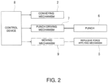
- FIG. 2 is a block diagram showing the press brake 1 according to Embodiment 1.
- the press brake 1 shown in FIGS. 1 and 2 can perform multistage bending with respect to a plate-shaped workpiece 90 that is long (and wide).
- a circular tube body, such as a skin of an aircraft body portion, which is relatively large in diameter can be manufactured from the workpieces 90.
- the press brake 1 includes a conveying mechanism (conveying device) 2, a die 3, a backup plate 4, a repulsive force applying mechanism (repulsive force applying device) 5, a punch 6, a punch driving mechanism (punch driving device) 7, and a control device 8.
- the conveying mechanism 2 intermittently conveys the workpiece 90.
- a specific configuration of the conveying mechanism 2 is not especially limited.
- the conveying mechanism 2 may be comprised by a conveyor, a robot including a hand at a tip of a robot arm, or the like.
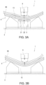
- the die 3 includes a pair of shoulder portions 11 and 12 and a groove portion 13 located between the pair of shoulder portions 11 and 12.
- the pair of shoulder portions 11 and 12 are arranged away from each other in a conveying direction of the workpiece 90 and support a rear surface of the workpiece 90.
- the die 3 includes a base plate 14 and a pair of lower die elements 15 and 16 standing on the base plate 14.
- the lower die elements 15 and 16 are arranged away from each other in the conveying direction, and top portions of the lower die elements 15 and 16 constitute the shoulder portions 11 and 12, respectively.
- the lower die elements 15 and 16 include opposing surfaces opposed to each other, and these opposing surfaces include tapered portions 15a and 16a that are inclined so as to approach each other in the conveying direction as the tapered portions 15a and 16a extend downward from the respective top portions.
- the tapered portions 15a and 16a define the groove portion 13, and the groove portion 13 has a substantially V-shaped section.
- the opposing surfaces include vertical portions 15b and 16b that are continuous from lower ends of the tapered portions 15a and 16a, extend vertically downward, and are opposed to each other in parallel.
- the die 3 shown in FIG. 1 is one example and is not limited to this configuration.
- the base plate 14 and the lower die elements 15 and 16 may be integrated as a single member.
- the lower die elements 15 and 16 may not include the tapered portions 15a and 16a.
- the lower die elements 15 and 16 may not include the vertical portions 15b and 16b.
- the shape of the die 3 can be suitably set.
- the backup plate 4 extends between the pair of shoulder portions 11 and 12 and covers the groove portion 13.
- the backup plate 4 includes a laminated structure in which thin plates are stacked on each other. With this, even if the workpiece 90 is pressed by the punch 6 to plastically deform, the backup plate 4 does not plastically deform but merely deforms within an elastic deformation region.
- the material of each thin plate is not especially limited, and each thin plate may be made of a metal material having a relatively large elastic deformation region.
- One example of the material of each thin plate is spring steel.
- the number of thin plates stacked is not especially limited and may be at least two or more or may be ten or more.
- the thin plates be merely stacked on each other without being adhered to each other with an adhesive.
- the adjacent thin plates may be partially connected to each other.
- the repulsive force applying mechanism 5 supports a portion of the backup plate 4 from below, the portion being located between the pair of shoulder portions 11 and 12.
- the repulsive force applying mechanism 5 applies upward repulsive force to the rear surface of the backup plate 4.
- the repulsive force applying mechanism 5 includes a spring 21 arranged between the lower die elements 15 and 16.
- the spring 21 is a coil spring, and an expansion/contraction direction of the spring 21 is an upper-lower direction.
- a lower end of the spring 21 is supported by the base plate 14 so as to be located between the vertical portions 15b and 16b of the lower die elements 15 and 16 and is supported by a floor surface of a work space together with the lower die elements 15 and 16.
- a plate 22 is attached to an upper end of the spring 21.
- the plate 22 is not essential.
- the upper end of the spring 21 may be in direct contact with the rear surface of the backup plate 4, or the upper end of the spring 21 and the rear surface of the backup plate 4 may be separated from each other without contacting each other.
- the repulsive force applying mechanism 5 may be a gas cylinder arranged such that a direction in which the repulsive force is generated is the upper-lower direction.
- the plate 22 is attached to a tip of a portion of the gas cylinder which portion generates the repulsive force with respect to the backup plate 4.
- the plate 22 is not essential.
- the repulsive force applying mechanism 5 is used when, for example, the punch 6 presses an edge portion of the workpiece 90 which has a large thickness and requires large forming force (pressing force of the punch 6). Therefore, the repulsive force applying mechanism 5 may not be used when pressing a non-edge portion (intermediate portion) of the workpiece 90.
- a method of switching between when the repulsive force applying mechanism 5 is used and when the repulsive force applying mechanism 5 is not used is not especially limited.
- the base plate 14 may be divided into portions supporting the lower die elements 15 and 16 and a portion supporting the spring 21, and the repulsive force applying mechanism 5 may be movable in the upper-lower direction or a horizontal direction.
- the repulsive force applying mechanism 5 can be automatically switched between a use state in which the repulsive force applying mechanism 5 is located between the lower die elements 15 and 16 and can be in surface contact with the rear surface of the backup plate 4 and a non-use state in which the repulsive force applying mechanism 5 retracts to a lower position or a lateral position so as not to be in surface contact with the rear surface of the backup plate 4. Or, a worker may manually perform work of timely attaching or detaching the repulsive force applying mechanism 5.
- the punch 6 is movable relative to the die 3 in the upper-lower direction.
- the die 3 is fixed to the floor surface, and the punch 6 is movable relative to the floor surface in the upper-lower direction.
- the die 3 may be movable in the upper-lower direction in addition to or instead of the punch 6.
- the punch 6 is arranged above the die 3, the backup plate 4, and the workpiece 90.
- the punch 6 moves downward to press a front surface of the workpiece 90.
- the backup plate 4 deforms together with the workpiece 90.
- This deformation of the backup plate 4 is within the elastic deformation region. With this, stress is applied as intended to a portion of the workpiece 90 which portion is located right under the punch 6, and a bending shape is properly given to the workpiece 90.
- the press brake 1 can perform the multistage bending.
- the punch driving mechanism 7 is an actuator that moves the punch 6 in the upper-lower direction.
- the punch driving mechanism 7 is comprised by a hydraulic cylinder arranged such that a rod thereof is directed in the upper-lower direction.
- the control device 8 controls at least operation of the conveying mechanism 2 and operation of the punch driving mechanism 7. In case automatically performing the switching between when the repulsive force applying mechanism 5 is used and when the repulsive force applying mechanism 5 is not used, the control device 8 also controls operation of a moving mechanism (moving device) 9 that moves the repulsive force applying mechanism 5.
- the action of the press brake 1 configured as above will be described with reference to FIG. 3 .
- the following operation (operating methods) of the conveying mechanism 2 and the punch driving mechanism 7 (or the punch 6) is executed (realized) by the driving control performed by the control device 8.
- the backup plate 4 In an initial state, the backup plate 4 is placed on the die 3, and the backup plate 4 is ready to receive the repulsive force from the repulsive force applying mechanism 5.
- the conveyance of the workpiece 90 starts, and the edge portion of the workpiece 90 reaches a position that is on the backup plate 4 and right under the punch 6, the conveyance of the workpiece 90 stops.
- the punch 6 is lowered.
- reaction force of the backup plate 4 is transmitted to the workpiece 90 by the backup plate 4 bending in a state where the workpiece 90 is sandwiched between the punch 6 and the backup plate 4.
- the repulsive force generated by the repulsive force applying mechanism 5 increases in accordance with the pressing of the punch 6 and is transmitted to the workpiece 90 in addition to the reaction force.
- the large reaction force (including the repulsive force) is obtained.
- the repulsive force is applied to the edge portion by the repulsive force applying mechanism 5. Therefore, the target bending shape can be accurately given to the edge portion of the workpiece 90. At this time, a large load is also applied to the punch 6.
- the punch 6 moves upward to retract from the die 3 and the workpiece 90. Then, after such operation is performed once or is intermittently performed multiple times, the workpiece 90 is conveyed by a predetermined conveyance amount. The conveyance of the workpiece 90 stops when the non-edge portion of the workpiece 90 is supported on the backup plate 4, i.e., when the edge portion of the workpiece 90 is located outside the pair of shoulder portions 11 and 12 in the conveying direction. When the conveyance of the workpiece 90 stops, the punch 6 moves downward again to press the workpiece 90. At this time, the repulsive force applying mechanism 5 is in a state of retracting from the die 3.
- the reaction force can be increased by the backup plate 4, the large reaction force which is generated when bending the edge portion is not generated.
- the repulsive force is not applied to the non-edge portion by the repulsive force applying mechanism 5.
- the press brake 1 is an apparatus which can realize the same bending by the same stroke every time and has high reproducibility.
- the workpiece 90 is intermittently conveyed. Each time the conveyance of the workpiece 90 stops, the punch 6 presses the workpiece 90. When a terminal end of the workpiece 90 is supported on the backup plate 4, i.e., when the edge portion of the workpiece 90 exists in a region sandwiched by the pair of shoulder portions 11 and 12, the punch 6 presses the terminal end of the workpiece 90 while applying the repulsive force to the backup plate 4 by the repulsive force applying mechanism 5 again.
- the desired bending shape can be accurately given to the workpiece 90, and the load applied to the punch 6 can be reduced as much as possible.
- the rear surface of the workpiece 90 is supported by a surface of the backup plate 4.
- the rear surface of the workpiece 90 is supported by the surface of the backup plate 4 (see FIG. 3B ).
- a large gap is not generated between the rear surface of the workpiece 90 and the upper surface of the backup plate 4. Therefore, for example, in case the punch 6 presses the vicinity of a portion (thickness step portion) of the workpiece 90 which portion has a relatively large thickness difference between upstream and downstream sides in the conveying direction, the generation of kink at this portion that changes in thickness can be suppressed, and a desired curvature can be given to the workpiece 90.
- the workpiece includes such thickness step portion
- the press brake 1 of the present embodiment as described above, the rear surface of the workpiece 90 is supported by the large surface of the backup plate 4. Therefore, the stress can be dispersed on the rear surface of the workpiece 90. Thus, the generation of the kink can be prevented even if the vicinity of the thickness step portion is pressed.
- the repulsive force applying mechanism 5 may be used when the punch 6 presses the non-edge portion of the workpiece 90.
- the plate 22 at the upper end of the spring 21 is arranged downwardly away from the rear surface of the backup plate 4 by a predetermined distance. Then, in case giving a large curvature radius to the workpiece 90, small pressing force is applied to a target portion by the punch 6. In this case, the plate 22 does not contact this portion of the rear surface of the workpiece 90, and only the reaction force of the backup plate 4 is applied to the workpiece 90 from below. Thus, the bending can be performed by relatively small pressing force. On the other hand, in case giving a small curvature radius to the workpiece, large pressing force is applied to the target portion by the punch 6.
- the plate 22 contacts this portion of the rear surface of the workpiece 90, and the repulsive force of the spring 21 is applied to the workpiece 90 in addition to the reaction force of the backup plate 4. Therefore, even if the bending process is performed with a relatively large pressing force, pressure can be appropriately applied to the rear surface of the workpiece 90.
- the spring 21 of the repulsive force applying mechanism 5 may be configured such that two or more spring elements having different elastic coefficients are connected to each other in series. In this case, if the pressing force of the punch 6 with respect to the workpiece 90 is small, the spring element having a smaller elastic coefficient contracts. With this, the surface pressure applied to the rear surface of the workpiece 90 can be prevented from becoming excessive. Then, if the pressing force of the punch 6 with respect to the workpiece 90 is large, the spring element having a larger elastic coefficient supports the workpiece 90. With this, appropriate surface pressure can be applied to the rear surface of the workpiece 90. Therefore, in this case, the plate 22 may be in surface contact with the rear surface of the backup plate 4 at all times.
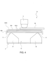
- FIG. 4 is a side view of a press brake 1A according to Embodiment 2.
- the press brake 1A according to Embodiment 2 is the same as the press brake 1 according to Embodiment 1 except that the backup plate 4 in Embodiment 2 is different in configuration from the backup plate 4 in Embodiment 1.
- the press brake 1A described in Embodiment 2 can be operated by the control device 8 described with reference to FIG. 2 .
- the backup plate 4 of the press brake 1A according to Embodiment 2 includes a laminated structure in which thin plates are stacked on each other.
- a thin plate (hereinafter referred to as a “front-surface plate 40") located closest to the punch 6 is different in configuration from the other thin plates (hereinafter referred to as “inner plates 41").
- each of the inner plates 41 is comprised by an entirely flat plate shape.
- the front-surface plate 40 includes a flat plate portion 40a and a curved portion 40b.
- the flat plate portion 40a has a flat plate shape that is substantially the same in area as the inner plate 41.
- the curved portion 40b is such a curved portion that both edge portions of the front-surface plate 40 in the conveying direction curve in a direction away from the punch 6. Then, edge portions of the inner plates 41 in the conveying direction are covered with the curved portion 40b.
- the positional deviation of the inner plates 41, located under the curved portion 40b, in the conveying direction can be prevented by the curved portion 40b of the front-surface plate 40. Moreover, since the edge portions of the inner plates 41 in the conveying direction are not exposed, the generation of scratches on the rear surface of the workpiece 90 by the contact with the edge portions can be prevented.
- circuitry or processing circuitry which includes general purpose processors, special purpose processors, integrated circuits, ASICs ("Application Specific Integrated Circuits"), conventional circuitry and/or combinations thereof which are configured or programmed to perform the disclosed functionality.
- Processors are considered processing circuitry or circuitry as they include transistors and other circuitry therein.
- the processor may be a programmed processor which executes a program stored in a memory.
- the circuitry, units, or means are hardware that carry out or are programmed to perform the recited functionality.
- the hardware may be any hardware disclosed herein or otherwise known which is programmed or configured to carry out the recited functionality.
- the hardware is a processor which may be considered a type of circuitry
- the circuitry, means, or units are a combination of hardware and software, the software being used to configure the hardware and/or processor.
- the present invention has the following aspects:
Landscapes
- Engineering & Computer Science (AREA)
- Mechanical Engineering (AREA)
- Bending Of Plates, Rods, And Pipes (AREA)
Applications Claiming Priority (3)
| Application Number | Priority Date | Filing Date | Title |
|---|---|---|---|
| JP2019122092 | 2019-06-28 | ||
| PCT/JP2020/025402 WO2020262684A1 (ja) | 2019-06-28 | 2020-06-26 | プレスブレーキおよびプレスブレーキの運転方法 |
| EP20832991.2A EP3991869B1 (de) | 2019-06-28 | 2020-06-26 | Pressbremse und verfahren zum betrieb einer pressbremse |
Related Parent Applications (2)
| Application Number | Title | Priority Date | Filing Date |
|---|---|---|---|
| EP20832991.2A Division-Into EP3991869B1 (de) | 2019-06-28 | 2020-06-26 | Pressbremse und verfahren zum betrieb einer pressbremse |
| EP20832991.2A Division EP3991869B1 (de) | 2019-06-28 | 2020-06-26 | Pressbremse und verfahren zum betrieb einer pressbremse |
Publications (3)
| Publication Number | Publication Date |
|---|---|
| EP4566735A2 true EP4566735A2 (de) | 2025-06-11 |
| EP4566735A3 EP4566735A3 (de) | 2025-06-18 |
| EP4566735B1 EP4566735B1 (de) | 2025-12-31 |
Family
ID=74061746
Family Applications (2)
| Application Number | Title | Priority Date | Filing Date |
|---|---|---|---|
| EP25171666.8A Active EP4566735B1 (de) | 2019-06-28 | 2020-06-26 | Verfahren zum betrieb einer abkantpresse |
| EP20832991.2A Active EP3991869B1 (de) | 2019-06-28 | 2020-06-26 | Pressbremse und verfahren zum betrieb einer pressbremse |
Family Applications After (1)
| Application Number | Title | Priority Date | Filing Date |
|---|---|---|---|
| EP20832991.2A Active EP3991869B1 (de) | 2019-06-28 | 2020-06-26 | Pressbremse und verfahren zum betrieb einer pressbremse |
Country Status (4)
| Country | Link |
|---|---|
| US (1) | US12076776B2 (de) |
| EP (2) | EP4566735B1 (de) |
| JP (1) | JP7169447B2 (de) |
| WO (1) | WO2020262684A1 (de) |
Citations (1)
| Publication number | Priority date | Publication date | Assignee | Title |
|---|---|---|---|---|
| JP2016059935A (ja) | 2014-09-17 | 2016-04-25 | 株式会社アマダホールディングス | プレスブレーキ及び多段曲げ加工方法 |
Family Cites Families (20)
| Publication number | Priority date | Publication date | Assignee | Title |
|---|---|---|---|---|
| US2781849A (en) * | 1952-03-25 | 1957-02-19 | Hartford Nat Bank & Trust Co | Method of forming small apertures in thin metal plate-shaped articles |
| US3263319A (en) * | 1964-02-28 | 1966-08-02 | Varian Associates | Method of cold deep drawing metal foil |
| US3566661A (en) * | 1968-07-29 | 1971-03-02 | Budd Co | Metal forming |
| JPS4965978A (de) * | 1972-10-30 | 1974-06-26 | ||
| JPS5311273B2 (de) | 1973-12-27 | 1978-04-20 | ||
| JPS5339183B2 (de) * | 1974-07-22 | 1978-10-19 | ||
| AT390575B (de) * | 1988-04-25 | 1990-05-25 | Haemmerle Ag | Verfahren zum biegen eines werkstueckes |
| JPH0281717U (de) * | 1988-12-02 | 1990-06-25 | ||
| JP3236310B2 (ja) * | 1991-06-27 | 2001-12-10 | 株式会社アマダ | 折曲げ加工装置 |
| US5542282A (en) * | 1994-03-09 | 1996-08-06 | Inner Act, Inc. | Markless press brake material protector |
| JPH1058043A (ja) * | 1996-08-26 | 1998-03-03 | Komatsu Ltd | 曲げ加工方法および曲げ加工装置 |
| US5956991A (en) * | 1998-08-19 | 1999-09-28 | Tseng; Shao-Chien | Forming device for shaped decoration panels |
| US7007530B2 (en) * | 2000-01-17 | 2006-03-07 | Amada Company, Limited | Bending method and bending device |
| US6865917B2 (en) * | 2003-03-27 | 2005-03-15 | Ford Motor Company | Flanging and hemming process with radial compression of the blank stretched surface |
| US8733145B1 (en) * | 2011-01-25 | 2014-05-27 | Valmont Newmark, Inc. | Method of forming a pole and saddle |
| AT512282B1 (de) * | 2012-06-18 | 2013-07-15 | Trumpf Maschinen Austria Gmbh | Biegepresse mit Winkelerfassungsvorrichtung |
| JP2014004606A (ja) * | 2012-06-25 | 2014-01-16 | Futaba:Kk | アール曲げ用金型 |
| JP6460695B2 (ja) * | 2014-03-31 | 2019-01-30 | 東京精密発條株式会社 | 金属板の曲げ加工装置 |
| JP6963387B2 (ja) * | 2017-01-18 | 2021-11-10 | 川崎重工業株式会社 | 曲げ加工方法 |
| JP6761054B2 (ja) * | 2017-01-31 | 2020-09-23 | 日軽金アクト株式会社 | 金型および該金型を用いた加工方法 |
-
2020
- 2020-06-26 WO PCT/JP2020/025402 patent/WO2020262684A1/ja not_active Ceased
- 2020-06-26 EP EP25171666.8A patent/EP4566735B1/de active Active
- 2020-06-26 EP EP20832991.2A patent/EP3991869B1/de active Active
- 2020-06-26 JP JP2021528291A patent/JP7169447B2/ja active Active
-
2021
- 2021-12-28 US US17/563,087 patent/US12076776B2/en active Active
Patent Citations (1)
| Publication number | Priority date | Publication date | Assignee | Title |
|---|---|---|---|---|
| JP2016059935A (ja) | 2014-09-17 | 2016-04-25 | 株式会社アマダホールディングス | プレスブレーキ及び多段曲げ加工方法 |
Also Published As
| Publication number | Publication date |
|---|---|
| EP3991869B1 (de) | 2025-11-12 |
| JP7169447B2 (ja) | 2022-11-10 |
| US12076776B2 (en) | 2024-09-03 |
| US20220118495A1 (en) | 2022-04-21 |
| EP3991869A4 (de) | 2023-07-12 |
| EP4566735B1 (de) | 2025-12-31 |
| EP4566735A3 (de) | 2025-06-18 |
| EP3991869A1 (de) | 2022-05-04 |
| JPWO2020262684A1 (de) | 2020-12-30 |
| WO2020262684A1 (ja) | 2020-12-30 |
Similar Documents
| Publication | Publication Date | Title |
|---|---|---|
| US10471493B2 (en) | Pressed component manufacturing method, press, and press line | |
| US10220427B2 (en) | Press-molding apparatus, press-molding method, and press-molded product | |
| CN104220184B (zh) | 由金属板制至少局部闭合的型材或管状构件的装置和方法 | |
| JP7133694B2 (ja) | 曲げ加工方法 | |
| US10668583B2 (en) | Assembly body manufacturing device and assembly body manufacturing method | |
| US20120011914A1 (en) | Lead processing apparatus, method for manufacturing semiconductor device, and lead processing die set | |
| CN110234445A (zh) | 模具和使用该模具的加工方法 | |
| EP3744437A1 (de) | Biegevorrichtung | |
| WO2009118918A1 (ja) | プレス加工装置及びプレス加工方法 | |
| US20180281043A1 (en) | Method for manufacturing metal component with three-dimensional edge and die sets for manufacturing the same | |
| JP2020028886A (ja) | 三次元プレス装置 | |
| EP3991870B1 (de) | Abkantpresse | |
| US11813659B2 (en) | Press forming method and press forming apparatus for automotive outer panel | |
| KR102512445B1 (ko) | 다공정 일원화 프레스 금형장치 | |
| EP3991869B1 (de) | Pressbremse und verfahren zum betrieb einer pressbremse | |
| US12070787B2 (en) | Press forming method and press apparatus | |
| JP6654901B2 (ja) | プレス成形装置、及びプレス成形方法 | |
| EP3511087B1 (de) | Werkzeug für eine biegepresse | |
| CN104203445B (zh) | 包括可调节的梁元件的挤压台或挤压梁 | |
| EP2908966B1 (de) | C-rahmenstruktur für biegungsausgleich und zugehöriges verfahren | |
| JP7050984B2 (ja) | ワーク端縁の残留応力低減方法 | |
| JP2002292428A (ja) | プレス型の増圧装置およびこれを用いた金型構造 | |
| JP4751052B2 (ja) | ダイ | |
| JP2003103335A (ja) | リベットを用いて2つ以上の構成部材を結合する方法および該方法を行うための装置 | |
| US9056352B2 (en) | Clipping die for clipping a component |
Legal Events
| Date | Code | Title | Description |
|---|---|---|---|
| PUAI | Public reference made under article 153(3) epc to a published international application that has entered the european phase |
Free format text: ORIGINAL CODE: 0009012 |
|
| STAA | Information on the status of an ep patent application or granted ep patent |
Free format text: STATUS: REQUEST FOR EXAMINATION WAS MADE |
|
| PUAL | Search report despatched |
Free format text: ORIGINAL CODE: 0009013 |
|
| 17P | Request for examination filed |
Effective date: 20250422 |
|
| AC | Divisional application: reference to earlier application |
Ref document number: 3991869 Country of ref document: EP Kind code of ref document: P |
|
| AK | Designated contracting states |
Kind code of ref document: A2 Designated state(s): AL AT BE BG CH CY CZ DE DK EE ES FI FR GB GR HR HU IE IS IT LI LT LU LV MC MK MT NL NO PL PT RO RS SE SI SK SM TR |
|
| AK | Designated contracting states |
Kind code of ref document: A3 Designated state(s): AL AT BE BG CH CY CZ DE DK EE ES FI FR GB GR HR HU IE IS IT LI LT LU LV MC MK MT NL NO PL PT RO RS SE SI SK SM TR |
|
| RIC1 | Information provided on ipc code assigned before grant |
Ipc: B21D 5/02 20060101AFI20250515BHEP |
|
| GRAP | Despatch of communication of intention to grant a patent |
Free format text: ORIGINAL CODE: EPIDOSNIGR1 |
|
| STAA | Information on the status of an ep patent application or granted ep patent |
Free format text: STATUS: GRANT OF PATENT IS INTENDED |
|
| INTG | Intention to grant announced |
Effective date: 20251016 |
|
| GRAS | Grant fee paid |
Free format text: ORIGINAL CODE: EPIDOSNIGR3 |
|
| GRAA | (expected) grant |
Free format text: ORIGINAL CODE: 0009210 |
|
| STAA | Information on the status of an ep patent application or granted ep patent |
Free format text: STATUS: THE PATENT HAS BEEN GRANTED |
|
| AC | Divisional application: reference to earlier application |
Ref document number: 3991869 Country of ref document: EP Kind code of ref document: P |
|
| AK | Designated contracting states |
Kind code of ref document: B1 Designated state(s): AL AT BE BG CH CY CZ DE DK EE ES FI FR GB GR HR HU IE IS IT LI LT LU LV MC MK MT NL NO PL PT RO RS SE SI SK SM TR |
|
| REG | Reference to a national code |
Ref country code: CH Ref legal event code: F10 Free format text: ST27 STATUS EVENT CODE: U-0-0-F10-F00 (AS PROVIDED BY THE NATIONAL OFFICE) Effective date: 20251231 Ref country code: GB Ref legal event code: FG4D |
|
| REG | Reference to a national code |
Ref country code: DE Ref legal event code: R096 Ref document number: 602020065041 Country of ref document: DE |
|
| REG | Reference to a national code |
Ref country code: IE Ref legal event code: FG4D |
|
| REG | Reference to a national code |
Ref country code: LT Ref legal event code: MG9D |
|
| PG25 | Lapsed in a contracting state [announced via postgrant information from national office to epo] |
Ref country code: NO Free format text: LAPSE BECAUSE OF FAILURE TO SUBMIT A TRANSLATION OF THE DESCRIPTION OR TO PAY THE FEE WITHIN THE PRESCRIBED TIME-LIMIT Effective date: 20260331 |
|
| PG25 | Lapsed in a contracting state [announced via postgrant information from national office to epo] |
Ref country code: FI Free format text: LAPSE BECAUSE OF FAILURE TO SUBMIT A TRANSLATION OF THE DESCRIPTION OR TO PAY THE FEE WITHIN THE PRESCRIBED TIME-LIMIT Effective date: 20251231 Ref country code: HR Free format text: LAPSE BECAUSE OF FAILURE TO SUBMIT A TRANSLATION OF THE DESCRIPTION OR TO PAY THE FEE WITHIN THE PRESCRIBED TIME-LIMIT Effective date: 20251231 |
|
| PG25 | Lapsed in a contracting state [announced via postgrant information from national office to epo] |
Ref country code: RS Free format text: LAPSE BECAUSE OF FAILURE TO SUBMIT A TRANSLATION OF THE DESCRIPTION OR TO PAY THE FEE WITHIN THE PRESCRIBED TIME-LIMIT Effective date: 20260331 |
|
| PG25 | Lapsed in a contracting state [announced via postgrant information from national office to epo] |
Ref country code: LV Free format text: LAPSE BECAUSE OF FAILURE TO SUBMIT A TRANSLATION OF THE DESCRIPTION OR TO PAY THE FEE WITHIN THE PRESCRIBED TIME-LIMIT Effective date: 20251231 |