EP4563973A1 - Interface failure rate measurement device and interface failure rate measurement method - Google Patents
Interface failure rate measurement device and interface failure rate measurement method Download PDFInfo
- Publication number
- EP4563973A1 EP4563973A1 EP23846600.7A EP23846600A EP4563973A1 EP 4563973 A1 EP4563973 A1 EP 4563973A1 EP 23846600 A EP23846600 A EP 23846600A EP 4563973 A1 EP4563973 A1 EP 4563973A1
- Authority
- EP
- European Patent Office
- Prior art keywords
- fracture
- adhesive
- rate measurement
- image
- interfacial
- Prior art date
- Legal status (The legal status is an assumption and is not a legal conclusion. Google has not performed a legal analysis and makes no representation as to the accuracy of the status listed.)
- Pending
Links
Images




Classifications
-
- G—PHYSICS
- G01—MEASURING; TESTING
- G01N—INVESTIGATING OR ANALYSING MATERIALS BY DETERMINING THEIR CHEMICAL OR PHYSICAL PROPERTIES
- G01N19/00—Investigating materials by mechanical methods
- G01N19/04—Measuring adhesive force between materials, e.g. of sealing tape, of coating
-
- G—PHYSICS
- G01—MEASURING; TESTING
- G01N—INVESTIGATING OR ANALYSING MATERIALS BY DETERMINING THEIR CHEMICAL OR PHYSICAL PROPERTIES
- G01N21/00—Investigating or analysing materials by the use of optical means, i.e. using sub-millimetre waves, infrared, visible or ultraviolet light
- G01N21/84—Systems specially adapted for particular applications
- G01N21/88—Investigating the presence of flaws or contamination
-
- G—PHYSICS
- G01—MEASURING; TESTING
- G01N—INVESTIGATING OR ANALYSING MATERIALS BY DETERMINING THEIR CHEMICAL OR PHYSICAL PROPERTIES
- G01N3/00—Investigating strength properties of solid materials by application of mechanical stress
- G01N3/02—Details
- G01N3/06—Special adaptations of indicating or recording means
- G01N3/068—Special adaptations of indicating or recording means with optical indicating or recording means
-
- G—PHYSICS
- G01—MEASURING; TESTING
- G01N—INVESTIGATING OR ANALYSING MATERIALS BY DETERMINING THEIR CHEMICAL OR PHYSICAL PROPERTIES
- G01N2203/00—Investigating strength properties of solid materials by application of mechanical stress
- G01N2203/0058—Kind of property studied
- G01N2203/0091—Peeling or tearing
-
- G—PHYSICS
- G01—MEASURING; TESTING
- G01N—INVESTIGATING OR ANALYSING MATERIALS BY DETERMINING THEIR CHEMICAL OR PHYSICAL PROPERTIES
- G01N2203/00—Investigating strength properties of solid materials by application of mechanical stress
- G01N2203/02—Details not specific for a particular testing method
- G01N2203/06—Indicating or recording means; Sensing means
- G01N2203/0641—Indicating or recording means; Sensing means using optical, X-ray, ultraviolet, infrared or similar detectors
- G01N2203/0647—Image analysis
Definitions
- the present invention relates to an interfacial fracture rate measurement apparatus and an interfacial fracture rate measurement method.
- FIG. 1 shows an example of an adhered part that uses an adhesive.
- an interface 11 of a first adherend 10 and an interface 21 of a second adherend 20 are bonded to each other by chemical and physical forces via an adhesion layer 30.
- a method involving applying an external force to an adhered part to fracture the adhered part and observing a fracture surface is known as a method of evaluating adhesion.
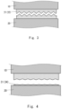
- Morphology of the fracture surface includes an interfacial fracture 32 (refer to Fig. 2 ) in which an adhesive layer is peeled off from an interface of one adherend, a cohesive fracture 33 (refer to Fig. 3 ) in which the adhesive layer is fractured, and a thin-layer cohesive fracture 34 in which a cohesive fracture occurs near the interface of one adherend (refer to Fig. 4 ).
- a fracture surface is a mixture of an interfacial fracture, a cohesive fracture, and a thin-layer cohesive fracture.
- adhesion is evaluated to be of high quality with little variation in adhesive strength if the interfacial fracture rate is 40% or lower.
- Patent Literature 1 discloses an inspection method of a bonded substrate including: cutting out a first chip including a test pattern from a bonded substrate constituted of a first substrate and a second substrate; separating the first chip and checking a fracture state; and evaluating a bonding state of a second chip in a region other than the test pattern of the bonded substrate.
- a bonded surface of the first chip is observed with an optical microscope (for example, paragraph 0049).
- Patent Literature 1 Japanese Unexamined Patent Application Publication No. 2018-059736
- Patent Literature 1 As described in Patent Literature 1 and the like, currently, a fracture surface is observed visually or under a microscope. With visual and microscopic observations, it may be particularly difficult to distinguish between an interfacial fracture and a thin-layer cohesive fracture. In addition, variability in determinations between observers cannot be ruled out. Therefore, there is a need to improve accuracy of determining a fracture state.
- the present invention was made in consideration of the circumstances described above and an object of the invention is to provide an interfacial fracture rate measurement apparatus and an interfacial fracture rate measurement method that measure an interfacial fracture rate with high accuracy.
- An interfacial fracture rate measurement apparatus includes: a light source unit configured to irradiate an adhesive fracture surface with light; an image capturing unit configured to capture an image of adhesive residue on the adhesive fracture surface; and image processing means for determining a site of an interfacial fracture from a captured image and calculating an area ratio of the site.
- the light source unit may be a UV light source unit and the image capturing unit may be configured to capture fluorescence emitted by the adhesive residue.
- the light source unit may be a polarized light source unit and the image capturing unit may include a polarizing plate and may be configured to capture transmitted light that is transmitted through the adhesive residue.
- An interfacial fracture rate measurement method includes the steps of: irradiating an adhesive fracture surface with UV light or polarized light; capturing fluorescence emitted by adhesive residue on the adhesive fracture surface or transmitted light that is transmitted through the adhesive residue; and determining a site of an interfacial fracture from an obtained image and calculating an area ratio of the site.
- an interfacial fracture rate measurement apparatus and an interfacial fracture rate measurement method that measure an interfacial fracture rate with high accuracy can be provided.
- visible light when simply referring to “visible light” or “UV light”, such light may be either polarized light or non-polarized light.
- polarized light when simply referring to “polarized light”, a wavelength of the light is not particularly limited.
- FIG. 5 is a schematic view showing an example of an interfacial fracture rate measurement apparatus 300.
- the interfacial fracture rate measurement apparatus 300 includes: a light source unit 50 configured to irradiate an adhesive fracture surface 40 with light 51; an image capturing unit 60 configured to capture light 41 emitted from adhesive residue 31 on the adhesive fracture surface 40; and image processing means 70 for determining a site of an interfacial fracture from a captured image 61 and calculating an area ratio of the site.
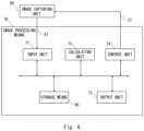
- Fig. 6 is a block diagram showing an example of the image processing means 70.
- the image processing means 70 in the example shown in Fig. 6 includes an input unit 71, an output unit 72, a calculating unit 73, a control unit 74, and storage means 80.
- a known personal computer, PDA, tablet terminal, or the like may be used as the image processing means 70.
- the input unit 71 is input means for accepting input of various kinds of information and need only include at least means for capturing the image 61 (for example, a terminal that can be connected to the image capturing unit 60) and may include a keyboard, a touch panel, various kinds of switches, or the like as needed.
- the output unit 72 is output means for outputting various kinds of necessary information and is configured as, for example, a monitor or the like.
- the calculating unit 73 determines at least a site of an interfacial fracture from a captured image and calculates an area ratio of the site. A specific example of a calculation method will be described later. In addition, when a specific camera or the like to be described later is used to capture an image, image processing is to be performed by the calculating unit 73.
- the calculating unit 73 is constituted of a CPU, various kinds of programs that are interpreted and executed on the CPU (including basic control programs such as an OS and application programs that run on the OS to realize specific functions), and an internal memory such as a RAM for storing programs and various kinds of data.
- the storage means 80 is storage means for storing various kinds of information necessary for processing by the image processing means 70 and is constituted of, for example, a hard disk or another recording medium.
- a light intensity DB database
- the storage means 80 may store the image 61 captured by the image capturing unit or a visible light image and may store a result of a calculation by the calculating unit 73. Note that the image 61 need not be stored when the image 61 is to be measured in real time.
- the storage means 80 may store the various kinds of programs described above or a program for executing an interfacial fracture rate measurement method.
- the control unit 74 controls at least each of the units that constitute the image processing means 70 and may further control capturing of images by the image capturing unit 60, control the light source unit 50, and the like.
- the control unit 74 is constituted of a CPU, various kinds of programs that are interpreted and executed on the CPU, and an internal memory such as a RAM for storing programs and various kinds of data.
- An interfacial fracture rate measurement apparatus is an apparatus that specifies an interfacial fracture rate on an adhesive fracture surface and the interfacial fracture rate measurement apparatus includes: a light source unit configured to irradiate an adhesive fracture surface with light; an image capturing unit configured to capture an image of adhesive residue on the adhesive fracture surface; and image processing means for determining a site of an interfacial fracture from a captured image and calculating an area ratio of the site.
- the interfacial fracture rate measurement apparatus eliminates variability in determinations between observers and improves calculation accuracy of interfacial fracture rates.
- An interfacial fracture rate measurement apparatus 100 includes: a UV light source unit 52 configured to irradiate the adhesive fracture surface 40 with UV light 53; the image capturing unit 60 configured to capture fluorescence 42 emitted from the adhesive residue 31 on the adhesive fracture surface 40; and the image processing means 70 for determining a site of an interfacial fracture from the captured image 61 and calculating an area ratio of the site.
- the interfacial fracture rate measurement apparatus focuses on the fact that many adhesives contain components that emit fluorescence and specifies an interfacial fracture site based on a correlation between a thickness of adhesive residue and fluorescence intensity. Specifically, fluorescence of the adhesive fracture surface is captured, a light intensity (fluorescence intensity) at each pixel of an obtained image is analyzed, the morphology of fracture at a location of the fracture surface corresponding to the pixel is specified according to the light intensity, an area ratio of at least a site of an interface fracture is calculated and, preferably, area ratios of a site of a thin-layer cohesive fracture and a site of a cohesive fracture are further calculated.
- the UV (ultraviolet) light source unit 52 need only include at least a light source that emits UV light. Examples of the light source include a UV lamp and a UV-LED. While the UV light source unit 52 may be solely constituted of a UV light source, the UV light source unit 52 preferably includes a high-pass filter that cuts visible light on an optical path between the UV light source and the adhesive fracture surface in order to improve measurement accuracy. There may be one UV light source unit 52 or a plurality of UV light source units 52 may be provided depending on a shape of the adhesive fracture surface and the like.
- a visible light source unit (not illustrated) may be further provided.
- the visible light source is not particularly limited and a known light source such as an LED or a fluorescent lamp can be used.
- the image capturing unit 60 need only include at least a camera that captures fluorescence of an adhesive fracture surface.
- a digital camera is preferable due to ease of import to the image processing means.
- a monochrome camera is preferable.
- a visible light image of the adhesive fracture surface is to be captured, a color digital camera is preferable.
- the image capturing unit 60 may be solely constituted of a camera, the image capturing unit 60 preferably includes a low-pass filter that cuts UV light on an optical path between the adhesive fracture surface and the camera in order to improve measurement accuracy.
- the image processing means 70 is as described earlier.
- FIG. 7 is a flowchart showing an example of an interfacial fracture rate measurement method according to the first embodiment.
- the interfacial fracture rate measurement method according to the present embodiment includes at least the steps of: preparing an article having an adhesive fracture surface to be measured (S10); capturing fluorescence of the adhesive fracture surface (S20); and calculating an area ratio of an interfacial fracture from an obtained image (S30).
- an article having an adhesive fracture surface to be measured is prepared.
- the article is a sample to be used for a quality control test of a product or a test for improvement of an adhered part of the product
- an adhesive fracture surface is prepared by peeling by a predetermined method.
- the predetermined method may be in accordance with various peel test methods specified in JIS or may be any method determined by a tester.
- an adhered part of a product in use may deteriorate over time or under specific environmental conditions and cause the product to peel.
- the peeled product is prepared as a sample.
- Masking may be applied to a peripheral edge of the adhesive fracture surface to be measured.
- Masking enables a range of an image to be readily specified.
- masking is appropriately selected and used from materials that do not emit fluorescence.
- a sample temperature when capturing an image is preferably constant.
- the temperature include methods such as keeping a sample holder at a constant temperature or controlling an environmental temperature so as to be constant.
- images may be captured continuously or intermittently by moving the image capturing unit 60 or the sample holder. In this case, the images are to be composited by the image processing means 70. Usually, measurements are preferably taken in the dark.
- an example shown in Fig. 8 is a method of determining a site of an interfacial fracture, a site of a thin-layer cohesive fracture, and a site of a cohesive fracture, respectively.
- a light intensity In at a pixel n in an image is referred to (S31).
- the pixel in this case is a smallest image unit in an image obtained as digital data.
- the light intensity In is compared with a predetermined value A (S32).
- a fracture state of a site corresponding to the pixel n on the adhesive fracture surface is determined to be an interfacial fracture.
- the light intensity In is further compared with another predetermined value B (S33).
- the fracture state of the site corresponding to the pixel n on the adhesive fracture surface is determined to be a thin-layer cohesive fracture.
- the fracture state of the site corresponding to the pixel n on the adhesive fracture surface is determined to be a cohesive fracture.
- the predetermined value A and the predetermined value B are preferably set in advance.
- the predetermined value A is a threshold between an interfacial fracture and a thin-layer cohesive fracture.
- the predetermined value A may be determined from a fluorescence intensity obtained by preparing the first adherend 10 or the second adherend 20 of a sample and performing a similar measurement to the present interfacial fracture rate measurement method with respect to a surface of the adherend.
- the predetermined value B is a threshold between a thin-layer cohesive fracture and a cohesive fracture.
- a thin-layer cohesive fracture may be appropriately set according to the purpose of an application or the like of the sample, a thickness of the adhesion layer 30, or the like.
- a thin-layer cohesive fracture may be determined when a thickness of the adhesive residue is equal to or less than 1 ⁇ m or a thin-layer cohesive fracture may be determined when the thickness of the adhesive residue is equal to or less than one-tenth of the thickness of the original adhesion layer 30.
- a sample for determining the predetermined value B may be prepared by applying an adhesive to the first adherend 10 to be 1 ⁇ m and curing the adhesive as necessary and a determination may be made from a fluorescence intensity obtained by performing a similar measurement to the present interfacial fracture rate measurement method with respect to the sample.
- Fig. 9 shows an example of performing image processing on an image of an adhesive fracture surface using the interfacial fracture rate measurement apparatus and the interfacial fracture rate measurement method according to the first embodiment.
- Fig. 10 shows a visible light image of a same adhesive fracture surface as in Fig. 9 .
- the example shown in Fig. 9 represents an image of the adhesive fracture surface having been divided into the interfacial fracture 32, the thin-layer cohesive fracture 34, and the cohesive fracture 33 according to S30 described above.
- the distinction between the interfacial fracture 32 and the thin-layer cohesive fracture 34 has been made clear by the interfacial fracture rate measurement method according to the first embodiment.
- an interfacial fracture, a thin-layer cohesive fracture, and a cohesive fracture can be measured with high accuracy.
- an adhesive fracture surface formed by peeling of an adhered part is formed by a set of two surfaces: a first adhesive fracture surface on a side of the first adherend 10 and a second adhesive fracture surface on a side of the second adherend 20 opposite to the first adhesive fracture surface. From a perspective of improving accuracy of specifying morphology of a fracture surface, it is preferable to respectively capture fluorescence of the first adhesive fracture surface and fluorescence of the opposing second adhesive fracture surface instead of only capturing an image of one adhesive fracture surface and to subject each captured fluorescence to image processing.
- measuring both surfaces enables a site of the second adhesive fracture surface that corresponds to a site where the first adhesive fracture surface was determined to be a cohesive fracture in the interfacial fracture rate measurement method according to the first embodiment to be specified as either a cohesive fracture or a thin-layer cohesive fracture. Accordingly, accuracies of a cohesive fracture rate and a thin-layer cohesive fracture rate are improved.
- fluorescence derived from the adherend is preferably separated based on a difference between a fluorescence spectrum of an adhesive and a fluorescence spectrum of the adherend. While the separation may be made by an optical system such as a filter or a prism when possible, a hyperspectral camera or a multispectral camera is preferably used as the camera of the image capturing unit 60. Using a hyperspectral camera or a multispectral camera to capture an image that includes wavelength information and adopting fluorescence intensity in a wavelength range that is less affected by adherend-derived fluorescence in the image processing means 70 enables highly accurate measurements to be made.
- a thin-layer cohesive fracture part may have low fluorescence intensity.
- lock-in processing, high-dynamic range processing, and the like may be performed.
- examples of lock-in processing include a method of creating a modulation signal by a computer, performing illuminance modulation of UV light at a predetermined modulation frequency corresponding to the signal, capturing the fluorescence continuously or intermittently for a predetermined time using the image capturing unit 60, performing lock-in processing using the predetermined modulation frequency of the modulation signal as a reference frequency in the image processing means 70, and determining a site of an interfacial fracture or the like based on a fluorescence intensity of an image subjected to the lock-in processing.
- noise can be significantly reduced and fluorescence sensitivity improves.
- fluorescence can be captured even when the present interfacial fracture rate measurement apparatus is used in a brightly lit area.
- examples of high-dynamic range processing include a method of using a UV light source that enables illuminance of UV light to be adjusted as the UV light source unit 52, capturing a plurality of images with the image capturing unit 60 under different conditions of UV illuminance, compositing the plurality of images in the image processing means 70 by high-dynamic range processing, and determining a site of an interfacial fracture based on a fluorescence intensity of an image obtained by the high-dynamic range processing.
- a measurement range of fluorescence intensity can be expanded and, for example, a thin-layer cohesive fracture part can be detected with high accuracy even when an adhesive contains components with high fluorescence intensity or when an adhesive layer is thick.
- a scanning-type apparatus may be used. Specifically, examples include a method of configuring the UV light source unit 52 so as to include a first optical fiber that emits UV light and configuring the image capturing unit 60 so as to include a second optical fiber to which fluorescence is incident, and operating the first optical fiber and the second optical fiber to capture fluorescence emitted from the adhesive residue on the adhesive fracture surface.
- Using a scanning-type apparatus also improves determination accuracy of a fine fractured state of an adhesive fracture surface.
- an interfacial fracture rate measurement apparatus including a confocal optical system may also be used to acquire fine irregular shapes of the first adherend or the second adherend.
- Specific configurations of the confocal optical system include a configuration in which a light source with high directionality such as a laser diode is preferably used as the UV light source unit 52 and an objective lens is provided on an optical path from the UV light source unit 52 to the adhesive fracture surface and, more specifically, examples include a method of using an optical system similar to known confocal microscopes.
- an image capturing unit including a three-dimensional camera is preferably used as the image capturing unit 60.
- the three-dimensional camera include a stereo system, a ToF system, and a structured illumination system.
- the present interfacial fracture rate measurement apparatus and the interfacial fracture rate measurement method require that an adhesive contain a material that emits fluorescence. While many adhesive components emit fluorescence, for example, some urethane-based adhesives do not. In this case, a small amount of a fluorescent substance can be added to the urethane-based adhesive being an adhesive component to create an adhesive that is applicable to the present apparatus. If a small amount of the fluorescent substance is used, the adhesive composition can be made to emit fluorescence without interfering with the performance of the adhesive.
- FIG. 12 is a schematic view showing an example of an interfacial fracture rate measurement apparatus 200 according to the second embodiment.
- the interfacial fracture rate measurement apparatus 200 according to the second embodiment includes: a polarized light source unit 54 configured to irradiate an adhesive fracture surface 40 with polarized light 55; an image capturing unit 63 configured to capture transmitted light 43 that is transmitted through adhesive residue 31 on the adhesive fracture surface 40; and image processing means 70.
- the image capturing unit 63 includes a polarizing plate 82 on an optical path of the transmitted light 43.
- the interfacial fracture rate measurement apparatus has been completed with a focus on the fact that polymeric materials that make up adhesives often have birefringent characteristics and in consideration of a correlation observed between a thickness of adhesive residue and polarization characteristics of transmitted light. Specifically, transmitted light that is transmitted through an adhesive fracture surface is captured, a light intensity at each pixel of an obtained image is analyzed, the morphology of fracture at a location of the fracture surface corresponding to the pixel is specified according to the light intensity, an area ratio of at least a site of an interface fracture is calculated and, preferably, area ratios of a site of a thin-layer cohesive fracture and a site of a cohesive fracture are further calculated.
- the polarized light source unit 54 need only be configured to be capable of irradiating the adhesive fracture surface 40 with polarized light.
- a configuration solely made of a polarized light source such as a polarized laser may be adopted or a combination of a non-polarized light source and a polarizing plate or a non-polarized light source and a polarization modulator may be adopted.
- the non-polarized light source is not particularly limited and a known light source such as an LED or a fluorescent lamp can be used.
- the polarizing plate and the polarization modulator are provided on an optical path between the light source and the adhesive fracture surface.
- a visible light source unit (not illustrated) may be further provided.
- a digital camera is preferable due to ease of import to the image processing means.
- the polarizing plate 82 include a quarter-wave plate.
- An arrangement of the image capturing unit 63 is appropriately adjusted according to a substance of the adherend 10 or the like.
- the adherend 10 is a highly light-reflective material such as metal
- the image capturing unit 63 is arranged so as to capture the transmitted light 43 having been reflected by the interface 11 as shown in the example in Fig. 11 .
- the adherend 10 has low transmittivity as in the case of a transparent film
- the image capturing unit 63 is arranged so as to capture the transmitted light 43 having been transmitted through the adhesive residue 31 and the adherend 10 (not illustrated).
- the preparation step (S10) and the image capturing step (S20) are as described in the first embodiment.
- UV light shall be read as polarized light and fluorescence shall be read as transmitted light.
- the area ratio calculation step (S30) will now be described. First, a relationship between light intensity of an image and a thickness of the adhesive residue 31 will be described with reference to Fig. 13 .
- a direction in which light travels is an X axis and a plane perpendicular to the X axis is a YZ plane.
- the polarized light 55 is linearly polarized light in the Z-axis direction.
- the transmitted light 43 becomes elliptic polarized light.
- a major-axis direction of the elliptic polarized light depends on a thickness of the adhesive residue 31.
- a Z-axis direction component of the transmitted light 43 is cut and light 83 corresponding to a Y-axis direction component is incident to the camera 62.
- light intensity of light incident to the camera 62 changes according to the thickness of the adhesive residue 31.
- a correlation between the thickness of the adhesive residue 31 and light intensity is not limited to a linear correlation.
- FIG. 14 is a method of determining a site of an interfacial fracture, a site of a thin-layer cohesive fracture, and a site of a cohesive fracture, respectively, using a crossed Nicol method and the polarized light 55 and the polarizing plate 82 are not rotated.
- a light intensity In at a pixel n in an image is referred to (S41).
- the light intensity In is compared with a predetermined numerical range C (S42).
- a fracture state of a site corresponding to the pixel n on the adhesive fracture surface is determined to be an interfacial fracture.
- the light intensity In is outside of the predetermined numerical range C
- the light intensity In is further compared with another predetermined numerical range D (S43).
- the fracture state of the site corresponding to the pixel n on the adhesive fracture surface is determined to be a thin-layer cohesive fracture.
- the fracture state of the site corresponding to the pixel n on the adhesive fracture surface is determined to be a cohesive fracture.
- the predetermined numerical ranges C and D described above are preferably set in advance.
- the predetermined numerical range C is a range of light intensity indicating an interfacial fracture and the predetermined numerical range D is a range of light intensity indicating a thin-layer cohesive fracture.
- Examples of a setting method include a method of preparing a same type of adhesive as an adhesive to be measured, forming coatings with a plurality of thicknesses, measuring the light intensity for each thickness by a method similar to that described above, and compiling a database.
- the relationship between thickness and light intensity may be calculated and stored in a database.
- FIG. 15 Another specific example of the area ratio calculation step (S30) will be described with reference to Fig. 15 .
- images are captured while rotating either the linearly polarized light 55 of the light source or the polarizing plate 82 described above at a predetermined speed. Accordingly, light intensity varies periodically.
- a difference in thicknesses of the adhesive residue 31 can be obtained based on phase information at any points in a captured image and, accordingly, sites of an interfacial fracture, a thin-layer cohesive fracture, and a cohesive fracture are determined.
- Fig. 15 focuses on two points for the sake of clarity of explanation, a plurality of pieces of phase information can be obtained by using three or more points, making it easier to determine the sites of an interfacial fracture, a thin-layer cohesive fracture, and a cohesive fracture.
- an interfacial fracture, a thin-layer cohesive fracture, and a cohesive fracture can be measured with high accuracy.
- Examples of a method of rotating the linearly polarized light 55 include using a combination of a non-polarized light source and a polarizing plate as the polarized light source unit 54 and rotating the polarizing plate.
- lock-in processing may be performed using a frequency based on a rotation speed of the linearly polarized light 55 or the polarizing plate 82 as a reference frequency and a site of an interfacial fracture may be determined based on a phase difference in an image subjected to the lock-in processing.
- Performing the lock-in processing enables noise to be significantly reduced and improves accuracy of determination of sites of an interfacial fracture, a thin-layer cohesive fracture, and a cohesive fracture.
- Modified examples of the second embodiment include the first modified example and the third to sixth modified examples described above in the first embodiment. Note that a combination of two or more of the modified examples may be applied to the second embodiment.
Landscapes
- Physics & Mathematics (AREA)
- Health & Medical Sciences (AREA)
- Life Sciences & Earth Sciences (AREA)
- Chemical & Material Sciences (AREA)
- Analytical Chemistry (AREA)
- Biochemistry (AREA)
- General Health & Medical Sciences (AREA)
- General Physics & Mathematics (AREA)
- Immunology (AREA)
- Pathology (AREA)
- Investigating, Analyzing Materials By Fluorescence Or Luminescence (AREA)
Applications Claiming Priority (2)
| Application Number | Priority Date | Filing Date | Title |
|---|---|---|---|
| JP2022120200 | 2022-07-28 | ||
| PCT/JP2023/027482 WO2024024870A1 (ja) | 2022-07-28 | 2023-07-27 | 界面破壊率測定装置、及び界面破壊率測定方法 |
Publications (1)
| Publication Number | Publication Date |
|---|---|
| EP4563973A1 true EP4563973A1 (en) | 2025-06-04 |
Family
ID=89706553
Family Applications (1)
| Application Number | Title | Priority Date | Filing Date |
|---|---|---|---|
| EP23846600.7A Pending EP4563973A1 (en) | 2022-07-28 | 2023-07-27 | Interface failure rate measurement device and interface failure rate measurement method |
Country Status (3)
| Country | Link |
|---|---|
| EP (1) | EP4563973A1 (https=) |
| JP (1) | JPWO2024024870A1 (https=) |
| WO (1) | WO2024024870A1 (https=) |
Families Citing this family (1)
| Publication number | Priority date | Publication date | Assignee | Title |
|---|---|---|---|---|
| EP4675261A1 (de) * | 2024-07-04 | 2026-01-07 | Schäfter + Kirchhoff GmbH | Verfahren und vorrichtung für eine bruchflächenanalyse |
Family Cites Families (9)
| Publication number | Priority date | Publication date | Assignee | Title |
|---|---|---|---|---|
| JPH05331438A (ja) * | 1992-05-30 | 1993-12-14 | Sony Corp | 蛍光性接着剤及び接着剤の塗布状態検査方法、検査装置 |
| JP2995714B2 (ja) * | 1995-03-27 | 1999-12-27 | 有限会社ユニオプト | 複屈折測定装置 |
| JP4680337B2 (ja) * | 1999-09-20 | 2011-05-11 | オリンパス株式会社 | 走査型レーザ顕微鏡 |
| JP4015383B2 (ja) * | 2001-07-02 | 2007-11-28 | オリンパス株式会社 | 内視鏡装置 |
| JP2018059736A (ja) | 2016-10-03 | 2018-04-12 | アズビル株式会社 | 接合基板、接合基板の検査方法、および半導体デバイスの製造方法。 |
| JP7007629B2 (ja) * | 2017-04-20 | 2022-01-24 | 国立大学法人秋田大学 | 対象物推定装置 |
| IL284589B2 (en) | 2019-01-31 | 2025-10-01 | Pfizer | 3–Carbonylamino–5–cyclopentyl–h1–pyrazole compounds with cdk2 inhibitory activity |
| EP4130106A4 (en) * | 2020-03-24 | 2023-12-13 | Mitsubishi Chemical Corporation | Fiber-reinforced composite material and bonded body |
| JP7535734B2 (ja) * | 2021-01-12 | 2024-08-19 | パナソニックIpマネジメント株式会社 | 部品撮像装置および部品実装装置 |
-
2023
- 2023-07-27 JP JP2024537213A patent/JPWO2024024870A1/ja active Pending
- 2023-07-27 WO PCT/JP2023/027482 patent/WO2024024870A1/ja not_active Ceased
- 2023-07-27 EP EP23846600.7A patent/EP4563973A1/en active Pending
Also Published As
| Publication number | Publication date |
|---|---|
| JPWO2024024870A1 (https=) | 2024-02-01 |
| WO2024024870A1 (ja) | 2024-02-01 |
Similar Documents
| Publication | Publication Date | Title |
|---|---|---|
| US10876975B2 (en) | System and method for inspecting a wafer | |
| EP2387796B1 (en) | System and method for inspecting a wafer | |
| US9863889B2 (en) | System and method for inspecting a wafer | |
| US20100079758A1 (en) | Inspection device, inspection method, and program | |
| EP0350869A1 (en) | Method of and apparatus for measuring film thickness | |
| CN102349017B (zh) | 焦点信息生成设备和焦点信息生成方法 | |
| SE1150498A1 (sv) | Flerkanalig ytplasmonresonanssensor utnyttjande strålprofilsellipsometri | |
| EP4563973A1 (en) | Interface failure rate measurement device and interface failure rate measurement method | |
| EP2410367A1 (en) | Image creating device and image creating method | |
| CN102778202A (zh) | 一种膜厚测量装置及方法 | |
| WO2004005902A1 (ja) | 光学的測定方法およびその装置 | |
| US20250052979A1 (en) | Surface sensing in automated sample analysis | |
| US11454795B2 (en) | Surface sensing in optical microscopy and automated sample scanning systems | |
| JP3657345B2 (ja) | 膜厚検査装置 | |
| US20240151937A1 (en) | Systems and methods for autofocus | |
| US6881587B2 (en) | Liquid-containing substance analyzing device and liquid-containing substance analyzing method | |
| JP2004177369A (ja) | 偏光イメージングを用いた選果システム | |
| KR100416497B1 (ko) | 박막패턴 검사장치 | |
| JP2002062218A (ja) | 光学的異方性物質評価装置 | |
| CN111220087B (zh) | 表面形貌检测方法 | |
| US20050036674A1 (en) | Method and system for determining shape of an object from a planar top view thereof | |
| JP2002039721A (ja) | 膜厚測定装置、膜厚測定方法および膜厚測定のためのプログラムを記憶した記録媒体 | |
| CN111189395A (zh) | 底切结构测量系统和底切结构测量方法 | |
| WO2025099834A1 (ja) | 検査装置及び検査方法 | |
| HK40006797A (en) | System and method for inspecting a wafer |
Legal Events
| Date | Code | Title | Description |
|---|---|---|---|
| STAA | Information on the status of an ep patent application or granted ep patent |
Free format text: STATUS: THE INTERNATIONAL PUBLICATION HAS BEEN MADE |
|
| PUAI | Public reference made under article 153(3) epc to a published international application that has entered the european phase |
Free format text: ORIGINAL CODE: 0009012 |
|
| STAA | Information on the status of an ep patent application or granted ep patent |
Free format text: STATUS: REQUEST FOR EXAMINATION WAS MADE |
|
| 17P | Request for examination filed |
Effective date: 20250130 |
|
| AK | Designated contracting states |
Kind code of ref document: A1 Designated state(s): AL AT BE BG CH CY CZ DE DK EE ES FI FR GB GR HR HU IE IS IT LI LT LU LV MC ME MK MT NL NO PL PT RO RS SE SI SK SM TR |
|
| DAV | Request for validation of the european patent (deleted) | ||
| DAX | Request for extension of the european patent (deleted) |