EP4557902A1 - Dispositif de refroidissement d'élément chauffant - Google Patents
Dispositif de refroidissement d'élément chauffant Download PDFInfo
- Publication number
- EP4557902A1 EP4557902A1 EP23839845.7A EP23839845A EP4557902A1 EP 4557902 A1 EP4557902 A1 EP 4557902A1 EP 23839845 A EP23839845 A EP 23839845A EP 4557902 A1 EP4557902 A1 EP 4557902A1
- Authority
- EP
- European Patent Office
- Prior art keywords
- cooling device
- heating element
- element cooling
- body part
- working fluid
- Prior art date
- Legal status (The legal status is an assumption and is not a legal conclusion. Google has not performed a legal analysis and makes no representation as to the accuracy of the status listed.)
- Pending
Links
Images



Classifications
-
- H—ELECTRICITY
- H05—ELECTRIC TECHNIQUES NOT OTHERWISE PROVIDED FOR
- H05K—PRINTED CIRCUITS; CASINGS OR CONSTRUCTIONAL DETAILS OF ELECTRIC APPARATUS; MANUFACTURE OF ASSEMBLAGES OF ELECTRICAL COMPONENTS
- H05K7/00—Constructional details common to different types of electric apparatus
- H05K7/20—Modifications to facilitate cooling, ventilating, or heating
- H05K7/2029—Modifications to facilitate cooling, ventilating, or heating using a liquid coolant with phase change in electronic enclosures
- H05K7/20336—Heat pipes, e.g. wicks or capillary pumps
-
- F—MECHANICAL ENGINEERING; LIGHTING; HEATING; WEAPONS; BLASTING
- F28—HEAT EXCHANGE IN GENERAL
- F28D—HEAT-EXCHANGE APPARATUS, NOT PROVIDED FOR IN ANOTHER SUBCLASS, IN WHICH THE HEAT-EXCHANGE MEDIA DO NOT COME INTO DIRECT CONTACT
- F28D15/00—Heat-exchange apparatus with the intermediate heat-transfer medium in closed tubes passing into or through the conduit walls ; Heat-exchange apparatus employing intermediate heat-transfer medium or bodies
- F28D15/02—Heat-exchange apparatus with the intermediate heat-transfer medium in closed tubes passing into or through the conduit walls ; Heat-exchange apparatus employing intermediate heat-transfer medium or bodies in which the medium condenses and evaporates, e.g. heat pipes
- F28D15/0233—Heat-exchange apparatus with the intermediate heat-transfer medium in closed tubes passing into or through the conduit walls ; Heat-exchange apparatus employing intermediate heat-transfer medium or bodies in which the medium condenses and evaporates, e.g. heat pipes the conduits having a particular shape, e.g. non-circular cross-section, annular
-
- F—MECHANICAL ENGINEERING; LIGHTING; HEATING; WEAPONS; BLASTING
- F28—HEAT EXCHANGE IN GENERAL
- F28D—HEAT-EXCHANGE APPARATUS, NOT PROVIDED FOR IN ANOTHER SUBCLASS, IN WHICH THE HEAT-EXCHANGE MEDIA DO NOT COME INTO DIRECT CONTACT
- F28D15/00—Heat-exchange apparatus with the intermediate heat-transfer medium in closed tubes passing into or through the conduit walls ; Heat-exchange apparatus employing intermediate heat-transfer medium or bodies
- F28D15/02—Heat-exchange apparatus with the intermediate heat-transfer medium in closed tubes passing into or through the conduit walls ; Heat-exchange apparatus employing intermediate heat-transfer medium or bodies in which the medium condenses and evaporates, e.g. heat pipes
- F28D15/0283—Means for filling or sealing heat pipes
-
- H—ELECTRICITY
- H05—ELECTRIC TECHNIQUES NOT OTHERWISE PROVIDED FOR
- H05K—PRINTED CIRCUITS; CASINGS OR CONSTRUCTIONAL DETAILS OF ELECTRIC APPARATUS; MANUFACTURE OF ASSEMBLAGES OF ELECTRICAL COMPONENTS
- H05K7/00—Constructional details common to different types of electric apparatus
- H05K7/20—Modifications to facilitate cooling, ventilating, or heating
- H05K7/2039—Modifications to facilitate cooling, ventilating, or heating characterised by the heat transfer by conduction from the heat generating element to a dissipating body
- H05K7/20409—Outer radiating structures on heat dissipating housings, e.g. fins integrated with the housing
-
- H—ELECTRICITY
- H10—SEMICONDUCTOR DEVICES; ELECTRIC SOLID-STATE DEVICES NOT OTHERWISE PROVIDED FOR
- H10W—GENERIC PACKAGES, INTERCONNECTIONS, CONNECTORS OR OTHER CONSTRUCTIONAL DETAILS OF DEVICES COVERED BY CLASS H10
- H10W40/00—Arrangements for thermal protection or thermal control
- H10W40/70—Fillings or auxiliary members in containers or in encapsulations for thermal protection or control
- H10W40/73—Fillings or auxiliary members in containers or in encapsulations for thermal protection or control for cooling by change of state
-
- F—MECHANICAL ENGINEERING; LIGHTING; HEATING; WEAPONS; BLASTING
- F28—HEAT EXCHANGE IN GENERAL
- F28D—HEAT-EXCHANGE APPARATUS, NOT PROVIDED FOR IN ANOTHER SUBCLASS, IN WHICH THE HEAT-EXCHANGE MEDIA DO NOT COME INTO DIRECT CONTACT
- F28D15/00—Heat-exchange apparatus with the intermediate heat-transfer medium in closed tubes passing into or through the conduit walls ; Heat-exchange apparatus employing intermediate heat-transfer medium or bodies
- F28D15/02—Heat-exchange apparatus with the intermediate heat-transfer medium in closed tubes passing into or through the conduit walls ; Heat-exchange apparatus employing intermediate heat-transfer medium or bodies in which the medium condenses and evaporates, e.g. heat pipes
- F28D15/04—Heat-exchange apparatus with the intermediate heat-transfer medium in closed tubes passing into or through the conduit walls ; Heat-exchange apparatus employing intermediate heat-transfer medium or bodies in which the medium condenses and evaporates, e.g. heat pipes with tubes having a capillary structure
-
- F—MECHANICAL ENGINEERING; LIGHTING; HEATING; WEAPONS; BLASTING
- F28—HEAT EXCHANGE IN GENERAL
- F28F—DETAILS OF HEAT-EXCHANGE AND HEAT-TRANSFER APPARATUS, OF GENERAL APPLICATION
- F28F2220/00—Closure means, e.g. end caps on header boxes or plugs on conduits
-
- F—MECHANICAL ENGINEERING; LIGHTING; HEATING; WEAPONS; BLASTING
- F28—HEAT EXCHANGE IN GENERAL
- F28F—DETAILS OF HEAT-EXCHANGE AND HEAT-TRANSFER APPARATUS, OF GENERAL APPLICATION
- F28F2275/00—Fastening; Joining
- F28F2275/06—Fastening; Joining by welding
Definitions
- the present disclosure relates to a heating element cooling device.
- Electronic components that constitute electronic devices generate heat when operating.
- Electronic devices such as computers, servers, and high-performance antenna devices include electronic components such as IC chips, CPUs, and transceiver elements. These electronic components (hereinafter referred to as "heating elements") generate a large amount of heat when operating. When the heating elements generating heat are not cooled, their performance may be significantly reduced or, in some cases, damaged, making operation difficult. Therefore, the heating elements should be cooled.
- Recent electronic devices are becoming slimmer, more integrated, and more high-performance, which is causing the gap between components to narrow and the heat load to increase. Accordingly, cooling of heating elements is almost essential, and most electronic devices are equipped with cooling devices to cool the heating elements.
- a heat pipe type or vapor chamber type cooling device that are equipped so that a certain refrigerant is circulated while the refrigerant changes phases depending on the surrounding temperature difference are widely used.
- the heat pipe type or vapor chamber type cooling device is manufactured by forming a hollow portion (or internal space) and by sintering a capillary wick, which is a porous body, inside a pipe-shaped (or panel-shaped) body tube (or body panel) made of a heat-conductive material.
- both ends of the cooling device may protrude beyond the heat sink.
- both ends of the cooling device do not include a wick portion or a separate support part, there is a problem that both ends of the cooling device are easily damaged by impact, or the like.
- a heating element cooling device comprising: a body part including a hollow portion in which working fluid is circulated and a wick portion which is disposed in at least a part of an inner wall of the body part and through which the working fluid flows to a heat source; a space part formed to extend from each of both ends of the body part and including a hollow portion; and a block part inserted into and welded to the space part.
- a heating element cooling device may have separate block parts coupled to both ends of a body part.
- the heating element cooling device it is possible to prevent both ends of the heating element cooling device from being easily damaged by impact or the like by combining separate block parts at both ends of the body part.
- alphanumeric codes such as first, second, i), ii), (a), (b), etc., in numbering components are used solely for the purpose of differentiating one component from the other but not to imply or suggest the substances, the order, or sequence of the components.
- parts "include” or “comprise” a component they are meant to further include other components, not excluding thereof unless there is a particular description contrary thereto.
- the terms such as 'unit,' 'module,' and the like refer to one or more units for processing at least one function or operation, which may be implemented by hardware, software, or a combination thereof.
- a heating element cooling device 1 is a heat dissipation component that can apply a heat dissipation method of the concept excluding the induction of phase change of refrigerant by a compressor.
- the heating element cooling device is designed to cool a heat generating element that is electrically driven and generates heat by transferring heat while causing a phase change solely by heat supplied from the outside under atmospheric pressure without using a compressor, and can be applied to a vapor chamber, a heat pipe, a heat sink, or the like.
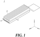
- FIG. 1 is a combined perspective view of a heating element cooling device according to one embodiment of the present disclosure.
- a heating element cooling device 1 of the present disclosure may include all or some of a body part 11, a block part 12, and a heat sink 13.
- the body part 11 may be a flat type part in which a length in a width direction (y-axis direction in FIG. 1 ) is relatively long compared to the length in a thickness direction (z-axis direction in FIG. 1 ).
- the body part 11 may include a hollow portion which is filled with refrigerant and through which the refrigerant can move.
- a wick portion 113 may be formed on an inner wall of the body part 11.
- the wick portion 113 may be formed by applying heat to an inner wall of the body part 11 using the high-density energy of a laser and scratching or wounding the inner wall to a certain depth or more.
- the wick portion 113 may be formed to generate a capillary phenomenon in a working fluid, such as a refrigerant, filling the body part 11 to cause the working fluid to flow.
- the wick portion 113 may cause a liquid working fluid to flow from a condense unit to an evaporate unit. For example, when heat is transferred to the inside of the heating element cooling device 1, the working fluid filling the inside may undergo a phase change due to the transferred heat.
- the working fluid that has undergone a phase change may radiate heat to the outside by using the wick portion 113 by means of surface tension and capillary force.
- the wick portion 113 may be formed parallel to a longitudinal direction (x-axis direction of FIG. 1 ) of the body part 11.
- the wick portions 113 may be formed in parallel at a predetermined interval in the width direction of the body part 11.
- the wick portion 113 may be formed to protrude from the upper and lower inner wall in the thickness direction of the body part 11.
- the heat sink 13 may be formed on at least a portion of the outer wall of the body part 11.
- the heat sink 13 may be formed on the outer wall in the thickness direction of the body part 11.
- the heat sinks 13 may be formed in parallel at a predetermined interval in the width direction of the body part 11.
- the heating element cooling device 1 of the present disclosure has the effect of additionally dissipating heat together with the body part 11 by forming the heat sink 13 on the outer wall of the body part 11.
- the heating element cooling device 1 of the present disclosure has the effect of being easy to manufacture even when the heat sink 13 is formed on the body part 11 by manufacturing the heating element cooling device 1 using an extrusion method.
- the heating element cooling device 1 of the present disclosure may further include a space part 111 and a bent part 112.
- the space part 111 may be formed at both ends of the body part 11 in the longitudinal direction.
- the space part 111 may be formed to protrude in the longitudinal direction of the body part 11 from the heat sink 13 formed on the outer wall of the body part 11.
- the working fluid can freely circulate within the body part 11. As a result, the fluidity of the working fluid increases, and the heat dissipation efficiency of the heating element cooling device 1 can be increased.
- the space part 111 may be formed to extend from both ends of the body part 11 in the longitudinal direction, and formed integrally with the body part 11.
- the space part 111 may include a hollow portion 111a which is filled with the working fluid and through which the working fluid moves.
- the space part 111 does not have the wick portion 113 or a separate support part formed on the inner wall. Therefore, when the space part 111 is sealed as is with a vacuum, there is a problem that both ends of the heating element cooling device 1 are easily damaged by external impact, or the like.
- the block part 12 of the heating element cooling device 1 of the present disclosure may be inserted into the hollow portion 111a of the space part 111.
- the block part 12 is inserted into the space part 111, and the block part 12 and the space part 111 may be joined to each other by welding.
- the block part 12 may have a shape corresponding to the width and length of the space part 111.
- the block part 12 may be inserted into the space part 111 and the entire circumference of the block part may be welded.
- the entire finished surface may be welded using the wobble welding method.
- the wobble welding refers to a method of performing welding while drawing a certain pattern during the welding. The welding conditions are explained as follows.
- the wavelength of the laser used may be 1030 nm.
- the welding may be performed with a dual beam having two beam characteristics, and an output ratio of a CORE beam and a RING beam may be 4:6.
- the output of the CORE beam may be 800 W and the output of the RING beam may be 1.2 KW.
- the size and frequency of the wobble may be 0.15 mm and 200 Hz, respectively.
- the output of the laser may be adjusted from 90% (1100 W) to 10% (750 W). That is, 90% of a certain length may be welded with 1100 W and the last 10% may be welded with 750 W.
- the welding conditions of the block part 12 and the space part 111 of the present disclosure are not limited thereto and may be designed in various ways as needed.
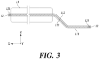
- the bent part 112 may be formed by bending at least a portion in the longitudinal direction of the body part 11.
- the bent part 112 may be bent at a predetermined angle within a range that does not impede the movement of the working fluid within the body part 11.
- the body part 11 excluding the bent part 112 may be formed in parallel.
- the present disclosure is not limited thereto, and the number of bent parts 112, the angle of the bent part, and the shape of the body part 11 may be designed in various ways as needed.
- FIG. 4 is an enlarged cross-sectional view of the body part and block part of the heating element cooling device according to one embodiment of the present disclosure.
- FIG. 5 is a view illustrating the block part of the heating element cooling device according to one embodiment of the present disclosure.
- the block part 12 of the heating element cooling device 1 of the present disclosure may include a support part 121 and a body 122.
- the support parts 121 may be arranged at a predetermined interval in the width direction of the block part 12.
- the support parts 121 may be arranged at a predetermined interval, but may be arranged in a manner aligned parallel to the wick portion 113 formed on the inner wall of the body part 11.
- the body 122 closes the hollow portion 111a of the space part 111, and the block part 12 and the space part 111 are welded, thereby sealing the space part 111 in a vacuum.
- the shape of the body 122 may correspond to the shape of the hollow portion 111a of the space part 111.
- the support part 121 may further include one or more grooves 121a through which the working fluid can circulate. Since the support part 121 includes one or more circular grooves 121a, the working fluid can smoothly circulate through the body part 11 and the space part 111.
- the grooves 121a formed in each support part 121 may be formed to correspond to the grooves 121a formed in the neighboring support part 121.
- the shapes and number of the support part 121 and the grooves 121a are not limited thereto and may be designed in various ways as needed.
- the block part 12 may have a shape corresponding to the width and length of the space part 111.
- the body 122 may have a shape corresponding to the hollow portion 111a of the space part 111.
- the thicknesses of the body 122 and the support part 121 may correspond to the thickness of the hollow portion 111a of the space part 111.
- the length of the block part 12 may correspond to the length of the space part 111. Therefore, the block part 12 may support the space part 111 in which the wick portion 113 or a separate support part is not formed on the inner wall.
- the block part 12 may be inserted into the space part 111, and the block part 12 and the space part 111 may be joined to each other by welding. Therefore, when the space part 111 is sealed as is with a vacuum, the block part 12 can support the space part 111, and thus, it is possible to prevent both ends of the heating element cooling device 1 from being damaged easily by external impact, or the like.
Landscapes
- Engineering & Computer Science (AREA)
- Physics & Mathematics (AREA)
- Thermal Sciences (AREA)
- Microelectronics & Electronic Packaging (AREA)
- Life Sciences & Earth Sciences (AREA)
- Sustainable Development (AREA)
- Mechanical Engineering (AREA)
- General Engineering & Computer Science (AREA)
- Cooling Or The Like Of Semiconductors Or Solid State Devices (AREA)
- Cooling Or The Like Of Electrical Apparatus (AREA)
Applications Claiming Priority (2)
| Application Number | Priority Date | Filing Date | Title |
|---|---|---|---|
| KR1020220087358A KR20240010648A (ko) | 2022-07-15 | 2022-07-15 | 발열소자 냉각장치 |
| PCT/KR2023/009082 WO2024014751A1 (fr) | 2022-07-15 | 2023-06-29 | Dispositif de refroidissement d'élément chauffant |
Publications (1)
| Publication Number | Publication Date |
|---|---|
| EP4557902A1 true EP4557902A1 (fr) | 2025-05-21 |
Family
ID=89537006
Family Applications (1)
| Application Number | Title | Priority Date | Filing Date |
|---|---|---|---|
| EP23839845.7A Pending EP4557902A1 (fr) | 2022-07-15 | 2023-06-29 | Dispositif de refroidissement d'élément chauffant |
Country Status (6)
| Country | Link |
|---|---|
| US (1) | US20250151234A1 (fr) |
| EP (1) | EP4557902A1 (fr) |
| JP (1) | JP2025523015A (fr) |
| KR (1) | KR20240010648A (fr) |
| CN (1) | CN119487985A (fr) |
| WO (1) | WO2024014751A1 (fr) |
Family Cites Families (10)
| Publication number | Priority date | Publication date | Assignee | Title |
|---|---|---|---|---|
| JPS6054282A (ja) * | 1983-08-31 | 1985-03-28 | Fujikura Ltd | ヒ−トパイプ用管体の製法 |
| JP2004060911A (ja) * | 2002-07-25 | 2004-02-26 | Namiki Precision Jewel Co Ltd | ヒートパイプ |
| KR200411135Y1 (ko) * | 2005-12-08 | 2006-03-10 | 주식회사 세기하이텍 | 평판형 히트파이프 |
| US8042606B2 (en) * | 2006-08-09 | 2011-10-25 | Utah State University Research Foundation | Minimal-temperature-differential, omni-directional-reflux, heat exchanger |
| KR20080028693A (ko) * | 2006-09-27 | 2008-04-01 | 잘만테크 주식회사 | 냉각장치 및 이에 채용된 히트파이프를 제조하는 방법 |
| JP2013007545A (ja) * | 2011-06-27 | 2013-01-10 | Stanley Electric Co Ltd | ヒートパイプ及びその製造方法並びそれを製造するプラズマエッチング装置 |
| US11454454B2 (en) * | 2012-03-12 | 2022-09-27 | Cooler Master Co., Ltd. | Flat heat pipe structure |
| JP5778302B2 (ja) * | 2014-02-27 | 2015-09-16 | 古河電気工業株式会社 | 熱輸送装置 |
| CN106885484A (zh) * | 2017-01-16 | 2017-06-23 | 深圳市迈安热控科技有限公司 | 一种多孔热管 |
| US11255610B2 (en) * | 2020-01-22 | 2022-02-22 | Cooler Master Co., Ltd. | Pulse loop heat exchanger and manufacturing method of the same |
-
2022
- 2022-07-15 KR KR1020220087358A patent/KR20240010648A/ko active Pending
-
2023
- 2023-06-29 JP JP2025501352A patent/JP2025523015A/ja active Pending
- 2023-06-29 CN CN202380053453.8A patent/CN119487985A/zh active Pending
- 2023-06-29 EP EP23839845.7A patent/EP4557902A1/fr active Pending
- 2023-06-29 WO PCT/KR2023/009082 patent/WO2024014751A1/fr not_active Ceased
-
2025
- 2025-01-11 US US19/017,425 patent/US20250151234A1/en active Pending
Also Published As
| Publication number | Publication date |
|---|---|
| WO2024014751A1 (fr) | 2024-01-18 |
| US20250151234A1 (en) | 2025-05-08 |
| CN119487985A (zh) | 2025-02-18 |
| JP2025523015A (ja) | 2025-07-17 |
| KR20240010648A (ko) | 2024-01-24 |
Similar Documents
| Publication | Publication Date | Title |
|---|---|---|
| US6942021B2 (en) | Heat transport device and electronic device | |
| US6956740B2 (en) | Heat sink with fins and manufacturing method thereof | |
| EP3172488B1 (fr) | Corps de refroidissement de source de lumière, ensemble de source lumineuse, luminaire et procédé de fabrication d'un corps de refroidissement de source de lumière ou ensemble de source de lumière | |
| KR20210058909A (ko) | 티타늄 열적 모듈 | |
| WO2020110972A1 (fr) | Dissipateur thermique | |
| EP3813098B1 (fr) | Chambre de vapeur | |
| JP6640401B1 (ja) | ヒートシンク | |
| WO2020230499A1 (fr) | Dissipateur thermique | |
| WO2020213581A1 (fr) | Dissipateur thermique | |
| CN112188792A (zh) | 散热器 | |
| JP2022063806A (ja) | 電子装置 | |
| EP4557902A1 (fr) | Dispositif de refroidissement d'élément chauffant | |
| EP3798564B1 (fr) | Chambre de vapeur de refroidissement d'un composant électronique | |
| US20240308006A1 (en) | Heating element cooling structure and method for manufacturing same | |
| US20060081360A1 (en) | Heat dissipation apparatus and manufacturing method thereof | |
| JP2003083688A (ja) | フィン一体型平面型ヒートパイプおよびその製造方法 | |
| JP7311057B2 (ja) | 熱拡散デバイスおよび電子機器 | |
| JP2022063805A (ja) | 冷却装置 | |
| KR20230077669A (ko) | 발열소자 냉각구조체 및 이의 제조방법 | |
| CN222263416U (zh) | 散热器 | |
| JP7575359B2 (ja) | 熱輸送体 | |
| JP2013245898A (ja) | ヒートパイプ | |
| WO2022181630A1 (fr) | Élément thermoconducteur et dispositif d'échange de chaleur | |
| WO2022181631A1 (fr) | Élément thermoconducteur et dispositif d'échange de chaleur | |
| JP2022181034A (ja) | 熱伝導部材 |
Legal Events
| Date | Code | Title | Description |
|---|---|---|---|
| STAA | Information on the status of an ep patent application or granted ep patent |
Free format text: STATUS: THE INTERNATIONAL PUBLICATION HAS BEEN MADE |
|
| PUAI | Public reference made under article 153(3) epc to a published international application that has entered the european phase |
Free format text: ORIGINAL CODE: 0009012 |
|
| STAA | Information on the status of an ep patent application or granted ep patent |
Free format text: STATUS: REQUEST FOR EXAMINATION WAS MADE |
|
| 17P | Request for examination filed |
Effective date: 20250211 |
|
| AK | Designated contracting states |
Kind code of ref document: A1 Designated state(s): AL AT BE BG CH CY CZ DE DK EE ES FI FR GB GR HR HU IE IS IT LI LT LU LV MC ME MK MT NL NO PL PT RO RS SE SI SK SM TR |
|
| DAV | Request for validation of the european patent (deleted) | ||
| DAX | Request for extension of the european patent (deleted) |