EP4557579A1 - Elektrischer permanentmagnet-synchronmotor - Google Patents
Elektrischer permanentmagnet-synchronmotor Download PDFInfo
- Publication number
- EP4557579A1 EP4557579A1 EP22951143.1A EP22951143A EP4557579A1 EP 4557579 A1 EP4557579 A1 EP 4557579A1 EP 22951143 A EP22951143 A EP 22951143A EP 4557579 A1 EP4557579 A1 EP 4557579A1
- Authority
- EP
- European Patent Office
- Prior art keywords
- permanent magnet
- recessed
- rotor
- electric motor
- core
- Prior art date
- Legal status (The legal status is an assumption and is not a legal conclusion. Google has not performed a legal analysis and makes no representation as to the accuracy of the status listed.)
- Pending
Links
Images


Classifications
-
- H—ELECTRICITY
- H02—GENERATION; CONVERSION OR DISTRIBUTION OF ELECTRIC POWER
- H02K—DYNAMO-ELECTRIC MACHINES
- H02K1/00—Details of the magnetic circuit
- H02K1/06—Details of the magnetic circuit characterised by the shape, form or construction
- H02K1/22—Rotating parts of the magnetic circuit
- H02K1/27—Rotor cores with permanent magnets
- H02K1/2706—Inner rotors
- H02K1/272—Inner rotors the magnetisation axis of the magnets being perpendicular to the rotor axis
- H02K1/274—Inner rotors the magnetisation axis of the magnets being perpendicular to the rotor axis the rotor consisting of two or more circumferentially positioned magnets
- H02K1/2753—Inner rotors the magnetisation axis of the magnets being perpendicular to the rotor axis the rotor consisting of two or more circumferentially positioned magnets the rotor consisting of magnets or groups of magnets arranged with alternating polarity
- H02K1/278—Surface mounted magnets; Inset magnets
- H02K1/2781—Magnets shaped to vary the mechanical air gap between the magnets and the stator
-
- H—ELECTRICITY
- H02—GENERATION; CONVERSION OR DISTRIBUTION OF ELECTRIC POWER
- H02K—DYNAMO-ELECTRIC MACHINES
- H02K21/00—Synchronous motors having permanent magnets; Synchronous generators having permanent magnets
- H02K21/12—Synchronous motors having permanent magnets; Synchronous generators having permanent magnets with stationary armatures and rotating magnets
- H02K21/14—Synchronous motors having permanent magnets; Synchronous generators having permanent magnets with stationary armatures and rotating magnets with magnets rotating within the armatures
- H02K21/16—Synchronous motors having permanent magnets; Synchronous generators having permanent magnets with stationary armatures and rotating magnets with magnets rotating within the armatures having annular armature cores with salient poles
-
- H—ELECTRICITY
- H02—GENERATION; CONVERSION OR DISTRIBUTION OF ELECTRIC POWER
- H02K—DYNAMO-ELECTRIC MACHINES
- H02K2201/00—Specific aspects not provided for in the other groups of this subclass relating to the magnetic circuits
- H02K2201/06—Magnetic cores, or permanent magnets characterised by their skew
-
- H—ELECTRICITY
- H02—GENERATION; CONVERSION OR DISTRIBUTION OF ELECTRIC POWER
- H02K—DYNAMO-ELECTRIC MACHINES
- H02K2213/00—Specific aspects, not otherwise provided for and not covered by codes H02K2201/00 - H02K2211/00
- H02K2213/03—Machines characterised by numerical values, ranges, mathematical expressions or similar information
Definitions
- the present disclosure relates to a permanent magnet synchronous electric motor.
- a terminal voltage generated by the electric motor needs to be equal to or lower than an input voltage.
- a terminal voltage Vt generated by a permanent magnet synchronous electric motor is expressed as follows using the dq-axis theory.
- Vd RId + ⁇ LqIq
- Vq RIq + ⁇ LdId + ⁇ m
- Vt ⁇ Vd 2 + Vq 2
- Vd is a d-axis voltage.
- Vq is a q-axis voltage.
- Ld is a d-axis inductance.
- Lq is a q-axis inductance.
- R is resistance.
- Id is a d-axis current.
- Iq is a q-axis current.
- ⁇ is an angular velocity.
- ⁇ m is a magnet magnetic flux.
- ⁇ m is an induced voltage.
- ⁇ Ld, ⁇ Lq, and ⁇ m increase in proportion to a rotation speed or velocity. Therefore, in a state in which an electric motor rotates at a high speed or the electric motor is driven at a high speed, the terminal voltage Vt increases.
- a flux-weakening control that inputs a negative d-axis current Id to the electric motor is known. According to such a flux-weakening control, it is possible to control the terminal voltage Vt to be equal to or lower than the input voltage Vi even when the electric motor rotates at a high speed or the electric motor is driven at a high speed.
- an amount of the induced voltage ⁇ m generated is reduced by applying the negative d-axis current Id to the electric motor, thereby preventing the terminal voltage Vt from becoming saturated during high-speed rotation.
- Ia ⁇ Id 2 + Iq 2
- the q-axis current Iq In order to generate the torque T, the q-axis current Iq is required. Therefore, a decrease in the q-axis current Iq causes a torque of the electric motor to decrease. Therefore, in order to output a large torque during high-speed rotation or high-speed driving, it is necessary to perform the effective flux-weakening control with a small amount of the d-axis current Id.
- Patent Document 1 discloses an effective flux-weakening control with a small amount of the d-axis current Id by increasing the d-axis inductance Ld.
- Patent Document 1 protrusions protruding in a radial direction from a rotor core are formed to be fitted into a plurality of permanent magnets disposed on a surface of the rotor core. Therefore, the d-axis inductance Ld is increased to effectively function the flux-weakening control, and a torque output of the electric motor during high-speed rotation is improved.
- Patent Document 1 Japanese Unexamined Patent Application, First Publication No. 2009-131070
- a circumferential position of the protruding portion of the rotor core intended to increase the d-axis inductance Ld is positioned at a center of the magnetic pole. Also, a shape of the protruding portion is mirror symmetrical with respect to the center of the magnetic pole.
- the present disclosure has been made to solve the above-described problems, and an objective of the present disclosure is to provide a permanent magnet synchronous electric motor capable of increasing a d-axis inductance Ld to perform an efficient flux-weakening control.
- a permanent magnet synchronous electric motor includes a stator, a rotor, and a plurality of permanent magnets.
- the rotor includes a rotor core constituted by an electrical steel sheet and having one or more protruding portions protruding in a radial direction toward the stator, and a rotating shaft fixed to the rotor core.
- the rotor is rotatably disposed with respect to the stator.
- Each of the plurality of permanent magnets includes an arc-shaped stator-facing surface facing the stator with a gap therebetween, a rotor-core-fixing surface positioned on a side opposite to the stator-facing surface and fixed to an outer circumferential surface of the rotor core, and a recessed portion connected to a part of the rotor-core-fixing surface and into which the protruding portion is fitted.
- the plurality of permanent magnets are aligned in a circumferential direction of the rotor. Polarities of the stator-facing surfaces of two permanent magnets adjacent to each other in the circumferential direction among the plurality of permanent magnets are different from each other.
- each of the plurality of permanent magnets has a first magnet end connected to the rotor-core-fixing surface and a second magnet end connected to the rotor-core-fixing surface and positioned on a side opposite to the first magnet end.
- the recessed portion of each of the plurality of permanent magnets has, a first recessed-portion end connected to the rotor-core-fixing surface and a second recessed-portion end connected to the rotor-core-fixing surface and positioned on a side opposite to the first recessed-portion end.
- the rotor-core-fixing surface includes a first region positioned between the first magnet end and the first recessed-portion end and a second region positioned between the second magnet end and the second recessed-portion end.
- the recessed portion is positioned between the first region and the second region. L1 ⁇ L2 is satisfied provided that a distance between the first magnet end and the first recessed-portion end in the first region is L1, and a distance between the second magnet end and the second recessed-portion end in the second region is L2.
- the d-axis inductance Ld can be increased, and an efficient flux-weakening control can be performed. Therefore, it is possible to improve a torque output of the permanent magnet synchronous electric motor during high-speed rotation.
- a permanent magnet synchronous electric motor according to embodiments will be described with reference to FIGS. 1A to 21 .
- the permanent magnet synchronous electric motor may be simply referred to as an electric motor.
- FIGS. 1 to 21 components the same as or similar to each other will be denoted by the same reference signs.
- an X direction, a Y direction, and a Z direction corresponding to a three-dimensional orthogonal coordinate system are shown (reference signs X, Y, and Z).
- the Z direction coincides with an axial direction of the permanent magnet synchronous electric motor.
- the Z direction coincides with the axial direction in which a rotating shaft positioned at an axial center of a rotor extends.
- the Z direction can also be referred to as a vertical direction in a two-stage skew structure.
- the X direction and the Y direction intersect (for example, are orthogonal to) the Z direction.
- the X direction and the Y direction intersect (for example, are orthogonal to) each other.
- circumferential direction and radial direction used in the following description correspond to a “circumferential direction” and a “radial direction” in a stator or rotor constituting the permanent magnet synchronous electric motor.
- circumferential direction corresponds to a rotation direction of the rotor.
- a circumferential direction around the rotating shaft of the rotor is the circumferential direction.
- radial direction means a direction of a radius of the rotor.
- radially outward means a direction from a center toward an outer circumferential portion of the rotor in the radial direction.
- radially inward means a direction from the outer circumferential portion toward the center of the rotor in the radial direction.
- FIGS. 1A and 1B are cross-sectional views showing a permanent magnet synchronous electric motor 100 according to the first embodiment.
- the permanent magnet synchronous electric motor 100 has a two-stage skew structure.
- FIG. 1A shows a cross section of a structure of one stage of the two-stage skew structure.
- FIG. 1B shows a cross section of a structure of the other stage of the two-stage skew structure.
- FIG. 1A shows a structure of an upper stage of the two-stage skew structure.
- FIG. 1B shows a structure of a lower stage of the two-stage skew structure.
- reference sign CL indicates a center line of the permanent magnet synchronous electric motor 100.
- Reference sign O indicates an axial center of a rotating shaft 23 to be described later. Positions of the center line CL and the axial center O are the same in FIGS. 1A and 1B .
- the center line CL corresponds to a d-axis of the permanent magnet synchronous electric motor 100.
- a position on the d-axis may be referred to as a d-axis position d1.
- Reference sign S denotes a magnet center line extending radially outward from the axial center O and passing through a circumferential center point of a permanent magnet 22 to be described later. That is, the magnet center line S passes through a circumferential center point C of a stator-facing surface 26 to be described later.
- a skew structure on the upper stage side and a skew structure on the lower stage side are displaced in the circumferential direction by a skew angle ⁇ .
- a shape of the skew structure shown in FIG. 1A is similar to a shape of the skew structure shown in FIG. 1B . Therefore, the structure of the permanent magnet synchronous electric motor 100 will be described with reference to FIG. 1A .
- the skew angle ⁇ will be described later.
- the permanent magnet synchronous electric motor 100 includes a stator 10 and a rotor 20.
- the permanent magnet synchronous electric motor 100 has a so-called stage skew structure.
- Each of a plurality of stages constituting the stage skew structure may be referred to as "each stage”.
- the skew structure on the upper stage side may be simply referred to as an "upper stage” and the skew structure on the lower stage side may be simply referred to as a "lower stage”.
- the terms “upper stage” and the “lower stage” are used for simplifying the description and do not define a vertical direction of the permanent magnet synchronous electric motor 100.
- the skew structure on the upper stage side may also be referred to as a first skew structure
- the skew structure on the lower stage side may also be referred to as a second skew structure.
- the first skew structure and the second skew structure are aligned in the Z direction.
- the stator 10 is disposed to surround an outer circumference of the rotor 20 via a gap 15 serving as a magnetic gap.
- the stator 10 includes a stator core 11 and a winding 14.
- the stator core 11 has a core back 12 formed in an annular shape in the circumferential direction, and a plurality of teeth 13 protruding radially inward from the core back 12.
- the winding 14 is wound around each of the plurality of teeth 13.
- the winding 14 wound around each of the teeth 13 may be referred to as a coil portion. In the example shown in FIG. 1A , one coil portion is provided for one of the teeth 13.
- the number of teeth 13 is twelve.
- the number of teeth 13 is not limited to twelve and may be determined as appropriate according to a design of the permanent magnet synchronous electric motor 100.
- the core back 12 is constituted by connecting a plurality of core blocks, each of which is formed in an arc shape, in an annular shape.
- a structure of the core back 12 is not limited to the structure shown in FIG. 1A .
- the core back 12 may be constituted by integrally forming a plurality of core blocks. Also, the core back 12 and the teeth 13 may be separated.
- the rotor 20 has a rotor core 21, the rotating shaft 23, and a plurality of permanent magnets 22.
- the rotor core 21 is constituted by stacking a plurality of electrical steel sheets in the Z direction.
- the electrical steel sheet may also be referred to as, for example, a core sheet.
- the rotating shaft 23 is fixed to the rotor core 21 to penetrate the rotor core 21 in the Z direction.
- the rotating shaft 23 may also be referred to as a shaft.
- Such a rotor 20 is rotatably disposed with respect to the stator 10 inside the permanent magnet synchronous electric motor 100.
- the rotor core 21 has a protruding portion 24 that protrudes in the radial direction.
- the protruding portion 24 protrudes radially outward toward the stator 10.
- a shape of the protruding portion 24 is rectangular.
- the number of protruding portions 24 is eight, corresponding to the number of the plurality of permanent magnets 22.
- the number of protruding portions 24 may be one or more.
- the plurality of permanent magnets 22 are disposed on an outer circumferential surface 28 of the rotor core 21 in the circumferential direction.
- the permanent magnet synchronous electric motor 100 having such a plurality of permanent magnets 22 is an example of a surface magnet type motor (SPM).
- the plurality of permanent magnets 22 each have a stator-facing surface 26 and a rotor-core-fixing surface 27.
- the stator-facing surface 26 faces the stator 10 with the gap 15 therebetween.
- the stator-facing surface 26 has an arc shape.
- the rotor-core-fixing surface 27 is positioned on a side opposite to the stator-facing surface 26.
- the rotor-core-fixing surface 27 is fixed to the outer circumferential surface 28 of the rotor core 21.
- a recessed portion 25 is provided at a part of the rotor-core-fixing surface 27. In other words, the recessed portion 25 is connected to a part of the rotor-core-fixing surface 27.
- the recessed portion 25 fits to the protruding portion 24.
- a shape of the recessed portion 25 is rectangular similarly to the shape of the protruding portion 24.
- the rotor-core-fixing surface 27 has a first region 27F and a second region 27S.
- the first region 27F and the second region 27S are each fixed to the outer circumferential surface 28 of the rotor core 21.
- the recessed portion 25 is positioned between the first region 27F and the second region 27S.
- the plurality of permanent magnets 22 are aligned in a circumferential direction of the rotor 20. Polarities of the stator-facing surfaces 26 of two permanent magnets 22 adjacent to each other in the circumferential direction among the plurality of permanent magnets 22 are different from each other.
- the plurality of permanent magnets 22 are disposed with their magnetization directions different from each other so that if a polarity of the stator-facing surface 26 of one of two adjacent permanent magnets 22 in the circumferential direction is an N pole, a polarity of the stator-facing surface 26 of the other is an S pole.
- the number of teeth 13 is twelve, the number of coil portions constituted by the windings 14 is twelve, and the number of permanent magnets is eight. That is, FIG. 1A shows a so-called 8-pole, 12-slot permanent magnet synchronous electric motor.
- a combination of the number of plurality of permanent magnets 22, teeth 13, and coil portions is not limited thereto. Also, in the example shown in FIG. 1A , the number of teeth 13 and the number of coil portions are the same, but the number of teeth 13 and the number of coil portions may be different.
- a central position of each of the plurality of permanent magnets 22 in the circumferential direction is displaced in the circumferential direction as it goes in the axial direction.
- the recessed portions 25 are displaced in different directions by a displacement amount ⁇ of the permanent magnets 22 shown in the same cross-sectional view.
- the plurality of permanent magnets 22 include a first magnet group 41 and a second magnet group 42 adjacent to each other in the Z direction.
- FIG. 1A shows the first magnet group 41.
- FIG. 1B shows the second magnet group 42.
- the rotor 20 has the stage skew structure.
- each of the plurality of permanent magnets 22 constituting the first magnet group 41 may be referred to as a first permanent magnet 22A.
- Each of the plurality of permanent magnets 22 constituting the second magnet group 42 may be referred to as a second permanent magnet 22B.
- the first permanent magnet 22A constituting the first magnet group 41 is disposed to be displaced from the center line CL by a displacement amount of ⁇ /2 in a counterclockwise direction in the circumferential direction. That is, in the counterclockwise direction, the magnet center line S shown in FIG. 1A is displaced from the center line CL by the displacement amount of ⁇ /2.
- the first permanent magnet 22A constituting the first magnet group 41 is displaced by ⁇ /2 with respect to the d-axis of the permanent magnet synchronous electric motor 100 in the counterclockwise direction in the circumferential direction.
- the second permanent magnet 22B constituting the second magnet group 42 is disposed to be displaced from the center line CL by a displacement amount of ⁇ /2 in a clockwise direction in the circumferential direction. That is, in the clockwise direction, the magnet center line S shown in FIG. 1B is displaced from the center line CL by the displacement amount of ⁇ /2.
- the second permanent magnet 22B constituting the second magnet group 42 is displaced by ⁇ /2 with respect to the d-axis of the permanent magnet synchronous electric motor 100 in the clockwise direction in the circumferential direction.
- the second permanent magnet 22B constituting the second magnet group 42 is displaced in the circumferential direction by a displacement amount ⁇ (skew angle ⁇ ) with respect to the first permanent magnet 22A constituting the first magnet group 41.
- the plurality of first permanent magnets 22A constituting the first magnet group 41 and the plurality of second permanent magnets 22B constituting the second magnet group 42 will be specifically described with reference to FIGS. 1A, 1B , 2A , and 2B .
- the permanent magnet 22 shown in FIG. 2A corresponds to the first permanent magnet 22A shown in FIG. 1 . However, if the permanent magnet shown in FIG. 2A is reversed in a left-right direction, the permanent magnet 22 shown in FIG. 2A becomes the second permanent magnet 22B. Therefore, description of the second permanent magnet 22B is omitted in FIG. 2A .
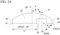
- the recessed portion 25 that engages with the protruding portion 24 will be described in detail with reference to FIG. 2A .
- FIG. 2A is an enlarged view showing a region near the permanent magnet 22, and is a cross-sectional view seen in the axial direction.
- FIG. 2A is an enlarged view showing the portion surrounded by the broken line portion A in FIG. 1A .
- the magnet center line S extending radially outward from the axial center O of the rotating shaft 23 and passing through the circumferential center point C of the permanent magnet 22 is defined as a circumferential center position CP of the permanent magnet 22.
- the center point C is positioned at a center in a circumferential direction of the stator-facing surface 26 of the permanent magnet 22.
- the center point C is positioned at a portion of the stator-facing surface 26 having an arc shape closest to the teeth 13.
- a line passing through a center of the protruding portion 24 and parallel to the magnet center line S is defined as a protruding portion center position TP.
- the protruding portion center position TP can also be referred to as a center of the protruding portion 24.
- the protruding portion center position TP is positioned at a center between a first recessed-portion end 35 and a second recessed-portion end 36.
- the plurality of permanent magnets 22 each have, in the circumferential direction, a first magnet end 31 connected to the rotor-core-fixing surface 27 and a second magnet end 32 connected to the rotor-core-fixing surface 27.
- the second magnet end 32 is positioned on a side opposite to the first magnet end 31 with respect to the circumferential center position CP.
- the permanent magnet 22 has a first side surface 33 and a second side surface 34 positioned opposite to each other in the circumferential direction.
- the first magnet end 31 corresponds to a portion at which the first side surface 33 and the rotor-core-fixing surface 27 are connected.
- the second magnet end 32 corresponds to a portion at which the second side surface 34 and the rotor-core-fixing surface 27 are connected.
- each of the plurality of permanent magnets 22 has, in the circumferential direction, the first recessed-portion end 35 connected to the rotor-core-fixing surface 27, and the second recessed-portion end 36 connected to the rotor-core-fixing surface 27 and positioned on a side opposite to the first recessed-portion end 35.
- the first region 27F of the rotor-core-fixing surface 27 is positioned between the first magnet end 31 and the first recessed-portion end 35.
- the second region 27S of the rotor-core-fixing surface 27 is positioned between the second magnet end 32 and the second recessed-portion end 36.
- first region 27F is a surface formed between the first magnet end 31 and the first recessed-portion end 35.
- the second region 27S is a surface formed between the second magnet end 32 and the second recessed-portion end 36.
- first region 27F and the second region 27S are positioned on both sides of the recessed portion 25.
- each of the plurality of permanent magnets 22 satisfies L1 ⁇ L2 and satisfies L1 > L2.
- the magnet center line S intersects the first region 27F.
- the magnet center line S intersects a line connecting the first magnet end 31 and the first recessed-portion end 35.
- the magnet center line S which is displaced from the center line CL by a displacement amount of ⁇ /2 in the counterclockwise direction, intersects the first region 27F of the permanent magnet 22.
- the magnet center line S which is displaced from the center line CL by a displacement amount of ⁇ /2 in the clockwise direction, intersects the first region 27F of the permanent magnet 22.
- FIG. 2B is a partial cross-sectional view in the Z direction showing a state in which the first permanent magnet 22A and the second permanent magnet 22B are overlapped.
- the first permanent magnet 22A is shown by a solid line
- the second permanent magnet 22B is shown by a dotted line.
- the first permanent magnet 22A has a first rotor-core-fixing surface 27A fixed to the outer circumferential surface 28 of the rotor core 21.
- the first rotor-core-fixing surface 27A is a surface corresponding to the rotor-core-fixing surface 27. Therefore, as shown in FIG. 2A , the first rotor-core-fixing surface 27A includes the first region 27F having a distance L1 and the first recessed-portion end 35, and the second region 27S having a distance L2 and the second recessed-portion end 36.
- the second permanent magnet 22B has a second rotor-core-fixing surface 27B fixed to the outer circumferential surface 28 of the rotor core 21.
- the second rotor-core-fixing surface 27B is a surface corresponding to the rotor-core-fixing surface 27. Therefore, as shown in FIG. 2A , the second rotor-core-fixing surface 27B includes the first region 27F having the distance L1 and the first recessed-portion end 35, and the second region 27S having the distance L2 and the second recessed-portion end 36.
- a circumferential center point of the first permanent magnet 22A is defined as a first center point C1.
- the first center point C1 corresponds to a circumferential center point of the stator-facing surface 26 of the first permanent magnet 22A.
- a circumferential center point of the second permanent magnet 22B is defined as a second center point C2.
- the second center point C2 corresponds to a circumferential center point of the stator-facing surface 26 of the second permanent magnet 22B.
- a line extending radially outward from the axial center O of the rotating shaft 23, passing through the first center point C1, and intersecting the first region 27F of the first permanent magnet 22A is defined as a first magnet center line S1.
- a line extending radially outward from the axial center O of the rotating shaft 23, passing through the second center point C2, and intersecting the first region 27F of the second permanent magnet 22B is defined as a second magnet center line S2.
- a midpoint between the first recessed-portion end 35 and the second recessed-portion end 36 of the first permanent magnet 22A in a direction 27AD parallel to the first rotor-core-fixing surface 27A is defined as a first midpoint 37A.
- a midpoint between the first recessed-portion end 35 and the second recessed-portion end 36 of the second permanent magnet 22B in a direction 27BD parallel to the second rotor-core-fixing surface 27B is defined as a second midpoint 37B.
- a line extending radially outward from the axial center O of the rotating shaft 23 and passing through the first midpoint 37A is defined as a first recessed portion center line N1.
- a line extending radially outward from the axial center O of the rotating shaft 23 and passing through the second midpoint 37B is defined as a second recessed portion center line N2.
- an angle between the first magnet center line S1 and the second magnet center line S2 is the skew angle ⁇ .
- an angle between the first recessed portion center line N1 and the second recessed portion center line N2 is an inter-recessed portion center angle M.
- the inter-recessed portion center angle M is smaller than the skew angle ⁇ .
- L1 ⁇ L2 is satisfied, and L1 > L2 is satisfied.
- a value obtained by dividing L1 by L2, that is, a value of L1/L2, is within a range of 1.0 ⁇ L1/L2 ⁇ 1.6.
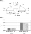
- FIG. 3 is an enlarged view showing a region near a permanent magnet constituting a conventional permanent magnet synchronous electric motor, and is a cross-sectional view seen in the axial direction.
- the stator is omitted in FIG. 3 .
- configurations not described are similar to those in FIG. 1A .
- the conventional permanent magnet synchronous electric motor has a permanent magnet 122 fixed to a stator.
- a protruding portion 124 of the stator of the conventional permanent magnet synchronous electric motor engages with a recessed portion 125 of the permanent magnet 122.
- Vt ⁇ Vd 2 + Vq 2
- Vd RId + ⁇ LqIq
- Vd is a d-axis voltage.
- Vq is a q-axis voltage.
- R is a phase resistance.
- Id is a d-axis current.
- Iq is a q-axis current.
- ⁇ m is a magnet magnetic flux.
- Ld is a d-axis inductance.
- Lq is a q-axis inductance.
- ⁇ is an angular velocity.
- f is a frequency.
- N is a rotation speed per minute.
- pn is the number of pole pairs.
- a so-called flux-weakening control that suppresses an increase in terminal voltage is known as a control method of increasing an output torque during high-speed rotation.
- This flux-weakening control is a control method of applying the d-axis current Id in a direction that weakens the magnet magnetic flux ⁇ m.
- this control method in a case in which the d-axis inductance Ld is small, it is necessary to cause a large amount of the d-axis current Id to flow to the electric motor.
- the torque T generated according to expression (6) contains a harmonic pulsation, and this torque pulsation is called as a torque ripple. Since the torque ripple can cause vibration or noise, measures to reduce it are generally taken.
- stage skew As one of the measures, a method of applying a structure called stage skew to a rotor structure is known.
- This structure is constituted by two or more stages of rotors, and when circumferential center positions of permanent magnets of the stages are compared, there is an angular difference, which is called as a skew angle.
- a skew angle When the angular difference is adjusted, it is possible to reduce the torque ripple in the entire electric motor.
- an electrical angle displacement (angular difference) of Pn ⁇ /2 occurs between the d-axis position d1 and the circumferential center position CP of the permanent magnet 22 in each stage of the rotor 20 throughout the entire motor.
- the first embodiment solves problems of the conventional permanent magnet synchronous electric motor.
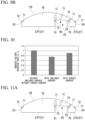
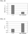
- the vertical axis represents the d-axis inductance Ld
- the horizontal axis represents a shape of the recessed portion.
- Rectangle refers to a shape of the recessed portion shown in FIGS. 2A and 3 .
- Sawtooth refers to a shape of a single tooth constituting a saw having a plurality of teeth.
- Arc refers to substantially a U-shape or substantially a C-shape.
- the d-axis inductance Ld in a case in which L1 L2 is normalized to 1.0.
- the "sawtooth” corresponds to the shape shown in modified example 1A to be described later.
- the "arc” corresponds to the shape shown in modified example 1B to be described later.
- the d-axis inductance Ld can be increased more than in the conventional permanent magnet synchronous electric motor.
- the permanent magnet synchronous electric motor 100 includes the first magnet group 41 and the second magnet group 42 adjacent to each other in the Z direction, and the rotor 20 has the stage skew structure between the first magnet group 41 and the second magnet group 42. Therefore, the d-axis inductance Ld can be efficiently improved.
- the inter-recessed portion center angle M is smaller than the skew angle ⁇ in the first embodiment.
- L1 ⁇ L2 is satisfied, and L1 > L2 is satisfied.
- a value of L1/L2 is in a range of 1.0 ⁇ L1/L2 ⁇ 1.6. Therefore, the d-axis inductance Ld can be improved more efficiently.
- FIG. 5 is an enlarged view showing a region near a permanent magnet constituting modified example 1A, and is a cross-sectional view seen in the axial direction.
- the recessed portion 25 has a first bottom end 51 and a second bottom end 52. Both the first bottom end 51 and the second bottom end 52 form a bottom 50 of the recessed portion 25. The second bottom end 52 is spaced apart from the first bottom end 51.
- H1 ⁇ H2 is satisfied.
- H1 ⁇ H2 is satisfied.
- L1 ⁇ L2 is satisfied.
- the d-axis inductance Ld can be increased more than in the conventional permanent magnet synchronous electric motor.
- FIG. 6 is an enlarged view showing a region near a permanent magnet constituting modified example 1B, and is a cross-sectional view seen in the axial direction. As shown in FIG. 6 , a surface 53 forming the bottom 50 of the recessed portion 25 has an arcuate shape. Furthermore, in the present modified example, L1 ⁇ L2 is satisfied.
- the d-axis inductance Ld can be increased more than in the conventional permanent magnet synchronous electric motor.
- a permanent magnet synchronous electric motor according to a second embodiment will be described.
- a recessed portion 25 that engages with a protruding portion 24 will be described in detail with reference to FIG. 7A .
- FIG. 7A is an enlarged view showing a region near a permanent magnet 22, and is a cross-sectional view seen in the axial direction.
- FIG. 7A corresponds to FIG. 2A and is an enlarged view showing the portion surrounded by the broken line portion A in FIG. 1A .
- the permanent magnet synchronous electric motor according to the second embodiment is constituted by a stator 10 and a rotor 20 similarly to FIG. 1 .
- the permanent magnet synchronous electric motor according to the second embodiment differs from the permanent magnet synchronous electric motor according to the first embodiment in that an inclined surface connected to a second bottom end 52 is formed inside the recessed portion 25.
- the recessed portion 25 has a first bottom end 51 and the second bottom end 52. Both the first bottom end 51 and the second bottom end 52 form a bottom 50 of the recessed portion 25. The second bottom end 52 is spaced apart from the first bottom end 51.
- the recessed portion 25 has a first inner wall 61 and a second inner wall 62.
- the first inner wall 61 is formed between a first recessed-portion end 35 and the first bottom end 51 and extends in the radial direction.
- the second inner wall 62 is formed between a second recessed-portion end 36 and the second bottom end 52.
- the second inner wall 62 has a vertical surface 63 and an inclined surface 64.
- the vertical surface 63 is connected to the second recessed-portion end 36 and extends in the radial direction.
- the inclined surface 64 is connected to the vertical surface 63 and the second bottom end 52, and linearly extends to be inclined with respect to the vertical surface 63.
- L1 ⁇ L2 is satisfied, and L1 > L2 is satisfied in the second embodiment.
- a value obtained by dividing L1 by L2, that is, a value of L1/L2, is within a range of 1.0 ⁇ L1/L2 ⁇ 1.6.
- the recessed portion 25 that engages with the protruding portion 24 will be described in detail with reference to FIG. 7B .
- FIG. 7B is an enlarged view showing a region near the permanent magnet 22, and is a cross-sectional view seen in the axial direction.
- FIG. 7B corresponds to FIG. 2A and is an enlarged view showing the portion surrounded by the broken line portion A in FIG. 1A .
- the permanent magnet synchronous electric motor according to modified example 2A is constituted by the stator 10 and the rotor 20 similarly to FIG. 1 .
- the permanent magnet synchronous electric motor according to modified example 2A differs from the permanent magnet synchronous electric motor according to the first embodiment in that a curved surface connected to the second bottom end 52 is formed inside the recessed portion 25.
- the recessed portion 25 has the first bottom end 51 and the second bottom end 52. Both the first bottom end 51 and the second bottom end 52 form the bottom 50 of the recessed portion 25.
- the second bottom end 52 is spaced apart from the first bottom end 51.
- the recessed portion 25 has the first inner wall 61 and the second inner wall 62.
- the first inner wall 61 is formed between the first recessed-portion end 35 and the first bottom end 51 and extends in the radial direction.
- the second inner wall 62 is formed between the second recessed-portion end 36 and the second bottom end 52.
- the second inner wall 62 has a curved surface 65 connected to the second bottom end 52.
- L1 ⁇ L2 is satisfied, and L1 > L2 is satisfied in modified example 2A.
- a value obtained by dividing L1 by L2, that is, a value of L1/L2, is within a range of 1.0 ⁇ L1/L2 ⁇ 1.6.
- a shape of the protruding portion 24 of the rotor core 21 is rectangular, and the protruding portion center position TP of the protruding portion 24 is displaced from the circumferential center of the permanent magnet 22.
- an outer shape of the stator-facing surface 26 is arcuate. In this case, at a position of a corner of the protruding portion 24, in other words, at the second bottom end 52 of the recessed portion 25, a distance between the stator-facing surface 26 and the second bottom end 52 is extremely small.
- a phenomenon called irreversible demagnetization in which a residual magnetic flux density Br of the permanent magnet decreases due to an effect of a temperature rise in the permanent magnet or an effect of a demagnetizing field in which a magnetic field from the stator is applied to the permanent magnet in a direction opposite to the magnetization direction, occurs.
- Ease of occurrence of such an irreversible demagnetization phenomenon is related to a coercive force of the permanent magnet and a permeance coefficient Pc that is determined by a magnetic circuit.
- the permeance coefficient Pc depends on a thickness of the magnet in a magnetization direction and magnetic resistance. In a magnetic circuit in which a magnetic gap between the stator and rotor is narrow such as a permanent magnet synchronous electric motor, the permeance coefficient Pc can be approximately determined by the following expression. Pc ⁇ Hm / gm
- Hm is a thickness of the permanent magnet in the magnetization direction.
- gm is a magnetic gap between the stator and the rotor. From expression (7), Pc decreases as the thickness Hm of the permanent magnet in the magnetization direction decreases. This decrease in Pc affects ease of occurrence of the irreversible demagnetization phenomenon.
- FIG. 8 is a diagram showing a comparison result in which the permanent magnet synchronous electric motor according to the first embodiment and the conventional permanent magnet synchronous electric motor are compared regarding the d-axis inductance Ld and an induced voltage decrease rate after demagnetization.
- FIGS. 9A and 9B show results obtained by calculating a demagnetization factor distribution using a magnetic field analysis on demagnetized states.
- FIG. 9A is a diagram showing a demagnetization factor distribution of the conventional permanent magnet synchronous electric motor.
- L1 L2 is satisfied as a condition of the permanent magnet.
- FIG. 9B is a diagram showing a demagnetization factor distribution of the permanent magnet synchronous electric motor according to the first embodiment.
- L1 ⁇ L2 and L1/L2 > 1.6 are satisfied as the condition of the permanent magnet.
- the regions indicated by reference signs 70, 71, and 72 show a progress state of demagnetization.
- the region indicated by reference sign 70 shows that an amount demagnetization progressed is the least.
- the region indicated by reference sign 72 shows that the amount demagnetization progressed is the largest.
- the region indicated by reference sign 71 indicates that the amount demagnetization progressed is larger than that of the region indicated by reference sign 70 and is smaller than that of the region indicated by reference sign 72.
- the region 72 arises in a portion in which a distance between the second bottom end 52 of the recessed portion 25 and the stator-facing surface 26 is small. In other words, it is found that a range in which demagnetization progresses extends as the distance between the corner of the protruding portion 24 and the stator-facing surface 26 becomes smaller.
- the second embodiment solves the above-described problems.
- FIG. 10 is a diagram showing a comparison result in which the permanent magnet synchronous electric motor according to the first embodiment, the permanent magnet synchronous electric motor according to the second embodiment, and the permanent magnet synchronous electric motor according to modified example 2A are compared regarding the induced voltage decrease rate after demagnetization.
- the induced voltage decrease rate of the permanent magnet 22 of the first embodiment is normalized to 1.0.
- "without the inclined surface, without the curved surface” corresponds to the first embodiment.
- “with the inclined surface” corresponds to the second embodiment.
- “with the curved surface” corresponds to modified example 2A.
- the induced voltage decrease rate in the second embodiment in which the permanent magnet 22 having the inclined surface 64 is used is smaller than that in the first embodiment.
- the induced voltage decrease rate in modified example 2A in which the permanent magnet 22 having the curved surface 65 is used is smaller than that in the first embodiment.
- FIGS. 11A to 11C show results obtained by calculating a demagnetization factor distribution using a magnetic field analysis on demagnetized states.
- FIG. 11A is a diagram showing the demagnetization factor distribution of the permanent magnet 22 according to the first embodiment.
- FIG. 11B is a diagram showing the demagnetization factor distribution of the permanent magnet 22 according to the second embodiment.
- FIG. 11C is a diagram showing the demagnetization factor distribution of the permanent magnet 22 according to modified example 2A.
- the regions indicated by reference signs 70, 71, and 72 show a progress state of demagnetization.
- the region indicated by reference sign 70 shows that an amount demagnetization progressed is the least.
- the region indicated by reference sign 72 shows that the amount demagnetization progressed is the largest.
- the region indicated by reference sign 71 indicates that the amount demagnetization progressed is larger than that of the region indicated by reference sign 70 and is smaller than that of the region indicated by reference sign 72.
- FIG. 12A is an enlarged view showing a region near a permanent magnet constituting modified example 2B, and is a cross-sectional view seen in the axial direction.
- the recessed portion 25 has the first bottom end 51 and the second bottom end 52. Both the first bottom end 51 and the second bottom end 52 form the bottom 50 of the recessed portion 25. The second bottom end 52 is spaced apart from the first bottom end 51.
- H1 ⁇ H2 is satisfied.
- H1 ⁇ H2 is satisfied.
- L1 ⁇ L2 is satisfied.
- a value of L1/L2 is within a range of 1.0 ⁇ L1/L2 ⁇ 1.6.
- the recessed portion 25 has the first inner wall 61 and the second inner wall 62.
- the first inner wall 61 is formed between the first recessed-portion end 35 and the first bottom end 51 and extends in the radial direction.
- the second inner wall 62 is formed between the second recessed-portion end 36 and the second bottom end 52.
- the second inner wall 62 has the vertical surface 63 and the inclined surface 64.
- the vertical surface 63 is connected to the second recessed-portion end 36 and extends in the radial direction.
- the inclined surface 64 is connected to the vertical surface 63 and the second bottom end 52, and linearly extends to be inclined with respect to the vertical surface 63.
- FIG. 12B is an enlarged view showing a region near a permanent magnet constituting modified example 2C, and is a cross-sectional view seen in the axial direction.
- the recessed portion 25 has the first inner wall 61 and the second inner wall 62.
- the first inner wall 61 is formed between the first recessed-portion end 35 and the first bottom end 51 and extends in the radial direction.
- the second inner wall 62 is formed between the second recessed-portion end 36 and the second bottom end 52.
- the second inner wall 62 has the curved surface 65 connected to the second bottom end 52.
- FIG. 13 is a diagram showing a comparison result in which the permanent magnet synchronous electric motor according to modified example 1A, the permanent magnet synchronous electric motor according to modified example 2B, and the permanent magnet synchronous electric motor according to modified example 2C are compared regarding the induced voltage decrease rate after demagnetization.
- the induced voltage decrease rate of the permanent magnet 22 of modified example 1A is normalized to 1.0.
- "without the inclined surface, without the curved surface” corresponds to modified example 1A.
- H1 ⁇ H2 is satisfied as described above, but the inclined surface or the curved surface is not formed in the recessed portion 25.
- “with the inclined surface” corresponds to modified example 2B.
- modified example 2C corresponds to modified example 2C.
- the induced voltage decrease rate in modified example 2B in which the permanent magnet 22 having the inclined surface 64 is used is smaller than that in modified example 1A.
- the induced voltage decrease rate in modified example 2C in which the permanent magnet 22 having the curved surface 65 is used is smaller than that in modified example 1A.
- FIGS. 14A to 14C show results obtained by calculating a demagnetization factor distribution using a magnetic field analysis on demagnetized states.
- FIG. 14A is a diagram showing the demagnetization factor distribution of the permanent magnet 22 according to modified example 1A.
- FIG. 14B is a diagram showing the demagnetization factor distribution of the permanent magnet 22 according to modified example 2B.
- FIG. 14C is a diagram showing the demagnetization factor distribution of the permanent magnet 22 according to modified example 2C.
- the regions indicated by reference signs 70, 71, and 72 show a progress state of demagnetization.
- the region indicated by reference sign 70 shows that an amount demagnetization progressed is the least.
- the region indicated by reference sign 72 shows that the amount demagnetization progressed is the largest.
- the region indicated by reference sign 71 indicates that the amount demagnetization progressed is larger than that of the region indicated by reference sign 70 and is smaller than that of the region indicated by reference sign 72.
- a permanent magnet synchronous electric motor according to a third embodiment will be described.
- FIG. 15 is a perspective view showing the permanent magnet synchronous electric motor according to the third embodiment.
- FIG. 16 is a perspective view that shows only a rotor core 21 including a protruding portion 24. In other words, FIG. 16 shows a state in which a plurality of permanent magnets 22 have been removed from the permanent magnet synchronous electric motor.
- the permanent magnet synchronous electric motor according to the third embodiment differs from the permanent magnet synchronous electric motor according to the first embodiment in that circumferential center positions CP of the permanent magnets 22 coincide at an upper stage and a lower stage.
- stator-facing surfaces 26 of the permanent magnets 22 aligned in the Z direction in which the rotating shaft 23 extends coincide with each other in the Z direction. There is no skew applied between the permanent magnets 22 aligned in the Z direction. Only a recessed portion 25 of each of the plurality of permanent magnets 22 and the protruding portion of the rotor core 21 are skewed.
- the permanent magnet synchronous electric motor according to the third embodiment will be described more specifically.
- the permanent magnet synchronous electric motor according to the third embodiment has an upper stage portion 100U and a lower stage portion 100L adjacent to the upper stage portion 100U in the Z direction.
- the upper stage portion 100U is an example of a first rotor portion.
- the lower stage portion 100L is an example of a second rotor portion.
- the plurality of permanent magnets 22 include a first magnet group 41 disposed in the upper stage portion 100U and a second magnet group 42 disposed in the upper stage portion 100U.
- the each of the plurality of permanent magnets 22 constituting the first magnet group 41 is the first permanent magnet described above.
- the each of the plurality of permanent magnets 22 constituting the second magnet group 42 is the second permanent magnet described above.
- the stator-facing surface 26 of the first permanent magnet constituting the first magnet group 41 coincides with the stator-facing surface 26 of the second permanent magnet constituting the second magnet group 42 in the Z direction.
- a position of a center point C in the circumferential direction of the stator-facing surface 26 of the first permanent magnet and a position of the center point C in the circumferential direction of the stator-facing surface 26 of the second permanent magnet coincide in the axial direction.
- the center point C of the stator-facing surface 26 in the circumferential direction has been described with reference to FIG. 2A .
- the protruding portion 24 of the rotor core 21 includes a first protruding portion 24U disposed in the upper stage portion 100U and a second protruding portion 24L disposed in the lower stage portion 100L.
- the first protruding portion 24U is fitted into the recessed portion 25 of the first permanent magnet constituting the first magnet group 41.
- the second protruding portion 24L is fitted into the recessed portion 25 of the second permanent magnet constituting the second magnet group 42.
- the second protruding portion 24L is displaced at a skew angle from the first protruding portion 24U.
- a position of the first protruding portion 24U (24) in the circumferential direction of the upper stage portion 100U and a position of the second protruding portion 24L (24) in the circumferential direction of the lower stage portion 100L are displaced from the circumferential center position CP of the permanent magnet 22 as shown in FIG. 2A .
- the position of the first protruding portion 24U in the circumferential direction of the upper stage portion 100U and a position of the second protruding portion 24L in the circumferential direction of the lower stage portion 100L are mirror symmetrical with respect to the circumferential center position CP of the permanent magnet 22.
- the manufacturing process for the rotor of the permanent magnet synchronous electric motor includes a magnetization process of attaching the permanent magnet 22 to the rotor core 21.
- the third embodiment solves the above-described problems.
- the position of the first protruding portion 24U (24) in the circumferential direction of the upper stage portion 100U and the position of the second protruding portion 24L (24) in the circumferential direction of the lower stage portion 100L are mirror symmetrical with respect to the circumferential center position CP. Due to an effect of the positions of the protruding portions 24, a phase difference occurs between harmonic components of the magnetic flux of the permanent magnets in the upper stage portion 100U and the lower stage portion 100L.
- the third embodiment it is possible to reduce the number of steps required for the magnetization process. Furthermore, in even a case in which a flux-weakening control is performed as in the conventional case, a high output of the electric motor can be achieved or the torque ripple can be reduced.
- a permanent magnet synchronous electric motor according to a fourth embodiment will be described.
- FIG. 18 is a perspective view showing a permanent magnet synchronous electric motor according to the fourth embodiment.
- FIG. 19 is a perspective view showing only a rotor core 21 including a protruding portion 24. In other words, FIG. 19 shows a state in which a plurality of permanent magnets 22 have been removed from the permanent magnet synchronous electric motor.
- the permanent magnet synchronous electric motor according to the fourth embodiment differs from the permanent magnet synchronous electric motor according to the first embodiment in that circumferential positions of the protruding portion 24 of the rotor core coincide at an upper stage and a lower stage.
- positions of the protruding portion 24 in the rotor core 21 coincide in the Z direction, and only recessed portions 25 of the permanent magnets 22 are skewed. Also, as shown in FIG. 18 , in each of the upper stage and the lower stage, a position of the recessed portion 25 of the permanent magnet 22 in the circumferential direction is displaced from a circumferential center position CP of the permanent magnet 22, and L1 ⁇ L2 is satisfied.
- the permanent magnet synchronous electric motor according to the fourth embodiment will be described more specifically.
- the permanent magnet synchronous electric motor according to the fourth embodiment has an upper stage portion 100U and a lower stage portion 100L adjacent to the upper stage portion 100U in the Z direction.
- the plurality of permanent magnets 22 include a first magnet group 41 disposed in the upper stage portion 100U and a second magnet group 42 disposed in the upper stage portion 100U.
- the plurality of permanent magnets 22 constituting the first magnet group 41 are each a first permanent magnet.
- the plurality of permanent magnets 22 constituting the second magnet group 42 are each a second permanent magnet.
- a stator-facing surface 26 of the first permanent magnet constituting the first magnet group 41 is displaced in the Z direction from the stator-facing surface 26 of the second permanent magnet constituting the second magnet group 42.
- a position of a center point C in the circumferential direction of the stator-facing surface 26 of the first permanent magnet and a position of a center point C in the circumferential direction of the stator-facing surface 26 of the second permanent magnet do not coincide in the axial direction.
- the center point C of the stator-facing surface 26 in the circumferential direction has been described with reference to FIG. 2A .
- the protruding portion 24 of the rotor core 21 extends continuously from the upper stage portion 100U to the lower stage portion 100L.
- the protruding portion 24 is fitted into the recessed portion 25 of the first permanent magnet constituting the first magnet group 41 and the recessed portion 25 of the second permanent magnet constituting the second magnet group 42.
- stator-facing surface 26 of the first permanent magnet constituting the first magnet group 41 is displaced at a skew angle from the stator-facing surface 26 of the second permanent magnet constituting the second magnet group 42.
- the position of the protruding portion 24 in the circumferential direction of the upper stage portion 100U and the position of the protruding portion 24 in the circumferential direction of the lower stage portion 100L are mirror symmetrical with respect to the circumferential center position CP of the permanent magnet 22.
- the rotor core is formed for each stage, and then the rotor core is fitted onto a rotating shaft so that a skew angle is generated.
- the fourth embodiment solves the above-described problems.
- the protruding portions 24 in the upper stage portion 100U and the lower stage portion 100L of the rotor core 21 are the same in the circumferential direction. Therefore, it is not necessary to manufacture the rotor core 21 to have the protruding portions 24 that are divided corresponding to each of the upper stage portion 100U and the lower stage portion 100L.
- the position of the recessed portion 25 of the permanent magnet 22 satisfies L1 ⁇ L2, and the circumferential center positions CP of the permanent magnets 22 in the upper stage and the lower stage are mirror symmetrical with respect to the position of the recessed portion 25, resulting in an angular difference.
- the d-axis inductance Ld can be increased more effectively in the case of the condition L1 ⁇ L2 in the fourth embodiment.
- the number of steps required for manufacturing the rotor core 21 can be reduced. Furthermore, in even a case in which a flux-weakening control is performed as in the conventional case, a high output of the electric motor can be achieved or the torque ripple can be reduced compared to the conventional structure.
Landscapes
- Engineering & Computer Science (AREA)
- Power Engineering (AREA)
- Permanent Field Magnets Of Synchronous Machinery (AREA)
Applications Claiming Priority (1)
| Application Number | Priority Date | Filing Date | Title |
|---|---|---|---|
| PCT/JP2022/027691 WO2024013929A1 (ja) | 2022-07-14 | 2022-07-14 | 永久磁石同期電動機 |
Publications (2)
| Publication Number | Publication Date |
|---|---|
| EP4557579A1 true EP4557579A1 (de) | 2025-05-21 |
| EP4557579A4 EP4557579A4 (de) | 2025-08-27 |
Family
ID=89536245
Family Applications (1)
| Application Number | Title | Priority Date | Filing Date |
|---|---|---|---|
| EP22951143.1A Pending EP4557579A4 (de) | 2022-07-14 | 2022-07-14 | Elektrischer permanentmagnet-synchronmotor |
Country Status (5)
| Country | Link |
|---|---|
| US (1) | US20250343454A1 (de) |
| EP (1) | EP4557579A4 (de) |
| JP (1) | JP7766803B2 (de) |
| CN (1) | CN119452546A (de) |
| WO (1) | WO2024013929A1 (de) |
Family Cites Families (8)
| Publication number | Priority date | Publication date | Assignee | Title |
|---|---|---|---|---|
| JPH1169676A (ja) * | 1997-08-06 | 1999-03-09 | Meidensha Corp | 永久磁石形回転電機の回転子構造 |
| JP2000324736A (ja) * | 1999-05-12 | 2000-11-24 | Mitsubishi Electric Corp | 永久磁石型モータ |
| JP2008148447A (ja) * | 2006-12-11 | 2008-06-26 | Nsk Ltd | 電動パワーステアリング装置用モータ |
| JP2009131070A (ja) | 2007-11-26 | 2009-06-11 | Denso Corp | 磁石式同期機 |
| US9172279B2 (en) | 2011-02-04 | 2015-10-27 | Mitsubishi Electric Corporation | Automotive embedded permanent magnet rotary electric machine |
| CN107026523A (zh) | 2016-02-01 | 2017-08-08 | 德昌电机(深圳)有限公司 | 单相电机及其转子 |
| JP2020088883A (ja) * | 2018-11-15 | 2020-06-04 | Dmg森精機株式会社 | ロータ |
| JP6987318B1 (ja) * | 2020-11-25 | 2021-12-22 | 三菱電機株式会社 | 永久磁石同期モータ |
-
2022
- 2022-07-14 WO PCT/JP2022/027691 patent/WO2024013929A1/ja not_active Ceased
- 2022-07-14 EP EP22951143.1A patent/EP4557579A4/de active Pending
- 2022-07-14 CN CN202280095289.2A patent/CN119452546A/zh active Pending
- 2022-07-14 JP JP2024533437A patent/JP7766803B2/ja active Active
- 2022-07-14 US US18/851,557 patent/US20250343454A1/en active Pending
Also Published As
| Publication number | Publication date |
|---|---|
| WO2024013929A1 (ja) | 2024-01-18 |
| EP4557579A4 (de) | 2025-08-27 |
| CN119452546A (zh) | 2025-02-14 |
| JP7766803B2 (ja) | 2025-11-10 |
| US20250343454A1 (en) | 2025-11-06 |
| JPWO2024013929A1 (de) | 2024-01-18 |
Similar Documents
| Publication | Publication Date | Title |
|---|---|---|
| US10404115B2 (en) | Rotary electric machine | |
| JP5930253B2 (ja) | 永久磁石埋込型回転電機 | |
| US7417346B2 (en) | Permanent magnet rotating electric machine | |
| EP2600498B1 (de) | Rotor für elektromotoren | |
| US10367385B2 (en) | Motor | |
| EP2270957A1 (de) | Permanentmagnet-synchronisationsmotor | |
| US9184648B2 (en) | Electric motor with permanent magnets in stator thereof | |
| US20210111602A1 (en) | Motor having asymmetric rotor core | |
| US10720807B2 (en) | Magnet-type rotor, rotary electric machine equipped with magnet-type rotor, and electric vehicle equipped with rotary electric machine | |
| CN116458036B (zh) | 永磁同步马达 | |
| EP4557579A1 (de) | Elektrischer permanentmagnet-synchronmotor | |
| US20240333053A1 (en) | Rotor and rotating electric machine | |
| JP2000253633A (ja) | 回転機 | |
| EP4152568A1 (de) | Rotor und elektromotor | |
| WO2022172479A1 (ja) | 回転電機 | |
| EP1638192A2 (de) | Magnetische Kreisstruktur für elektrische Drehmaschinen | |
| EP4468565A1 (de) | Elektrische drehmaschine | |
| EP4425756A1 (de) | Rotor und permanentmagnetsynchronmotor | |
| WO2023218743A1 (ja) | ロータ及びこれを備えたipmモータ | |
| JP2023102516A (ja) | ロータ及び回転電機 | |
| CN110268601A (zh) | 旋转电机的控制装置、旋转电机及旋转电机的控制方法 |
Legal Events
| Date | Code | Title | Description |
|---|---|---|---|
| STAA | Information on the status of an ep patent application or granted ep patent |
Free format text: STATUS: THE INTERNATIONAL PUBLICATION HAS BEEN MADE |
|
| PUAI | Public reference made under article 153(3) epc to a published international application that has entered the european phase |
Free format text: ORIGINAL CODE: 0009012 |
|
| STAA | Information on the status of an ep patent application or granted ep patent |
Free format text: STATUS: REQUEST FOR EXAMINATION WAS MADE |
|
| 17P | Request for examination filed |
Effective date: 20241011 |
|
| AK | Designated contracting states |
Kind code of ref document: A1 Designated state(s): AL AT BE BG CH CY CZ DE DK EE ES FI FR GB GR HR HU IE IS IT LI LT LU LV MC MK MT NL NO PL PT RO RS SE SI SK SM TR |
|
| A4 | Supplementary search report drawn up and despatched |
Effective date: 20250730 |
|
| RIC1 | Information provided on ipc code assigned before grant |
Ipc: H02K 1/278 20220101AFI20250724BHEP Ipc: H02K 1/2781 20220101ALI20250724BHEP Ipc: H02K 21/16 20060101ALI20250724BHEP |
|
| DAV | Request for validation of the european patent (deleted) | ||
| DAX | Request for extension of the european patent (deleted) |