EP4556715A1 - Spiralverdichter - Google Patents
Spiralverdichter Download PDFInfo
- Publication number
- EP4556715A1 EP4556715A1 EP24826859.1A EP24826859A EP4556715A1 EP 4556715 A1 EP4556715 A1 EP 4556715A1 EP 24826859 A EP24826859 A EP 24826859A EP 4556715 A1 EP4556715 A1 EP 4556715A1
- Authority
- EP
- European Patent Office
- Prior art keywords
- refrigerant gas
- motor
- chamber
- inlet
- scroll compressor
- Prior art date
- Legal status (The legal status is an assumption and is not a legal conclusion. Google has not performed a legal analysis and makes no representation as to the accuracy of the status listed.)
- Pending
Links
Images


Classifications
-
- F—MECHANICAL ENGINEERING; LIGHTING; HEATING; WEAPONS; BLASTING
- F04—POSITIVE - DISPLACEMENT MACHINES FOR LIQUIDS; PUMPS FOR LIQUIDS OR ELASTIC FLUIDS
- F04C—ROTARY-PISTON, OR OSCILLATING-PISTON, POSITIVE-DISPLACEMENT MACHINES FOR LIQUIDS; ROTARY-PISTON, OR OSCILLATING-PISTON, POSITIVE-DISPLACEMENT PUMPS
- F04C18/00—Rotary-piston pumps specially adapted for elastic fluids
- F04C18/02—Rotary-piston pumps specially adapted for elastic fluids of arcuate-engagement type, i.e. with circular translatory movement of co-operating members, each member having the same number of teeth or tooth-equivalents
- F04C18/0207—Rotary-piston pumps specially adapted for elastic fluids of arcuate-engagement type, i.e. with circular translatory movement of co-operating members, each member having the same number of teeth or tooth-equivalents both members having co-operating elements in spiral form
- F04C18/0215—Rotary-piston pumps specially adapted for elastic fluids of arcuate-engagement type, i.e. with circular translatory movement of co-operating members, each member having the same number of teeth or tooth-equivalents both members having co-operating elements in spiral form where only one member is moving
-
- F—MECHANICAL ENGINEERING; LIGHTING; HEATING; WEAPONS; BLASTING
- F04—POSITIVE - DISPLACEMENT MACHINES FOR LIQUIDS; PUMPS FOR LIQUIDS OR ELASTIC FLUIDS
- F04C—ROTARY-PISTON, OR OSCILLATING-PISTON, POSITIVE-DISPLACEMENT MACHINES FOR LIQUIDS; ROTARY-PISTON, OR OSCILLATING-PISTON, POSITIVE-DISPLACEMENT PUMPS
- F04C29/00—Component parts, details or accessories of pumps or pumping installations, not provided for in groups F04C18/00 - F04C28/00
- F04C29/0042—Driving elements, brakes, couplings, transmissions specially adapted for pumps
- F04C29/0085—Prime movers
-
- F—MECHANICAL ENGINEERING; LIGHTING; HEATING; WEAPONS; BLASTING
- F04—POSITIVE - DISPLACEMENT MACHINES FOR LIQUIDS; PUMPS FOR LIQUIDS OR ELASTIC FLUIDS
- F04C—ROTARY-PISTON, OR OSCILLATING-PISTON, POSITIVE-DISPLACEMENT MACHINES FOR LIQUIDS; ROTARY-PISTON, OR OSCILLATING-PISTON, POSITIVE-DISPLACEMENT PUMPS
- F04C18/00—Rotary-piston pumps specially adapted for elastic fluids
- F04C18/02—Rotary-piston pumps specially adapted for elastic fluids of arcuate-engagement type, i.e. with circular translatory movement of co-operating members, each member having the same number of teeth or tooth-equivalents
- F04C18/0207—Rotary-piston pumps specially adapted for elastic fluids of arcuate-engagement type, i.e. with circular translatory movement of co-operating members, each member having the same number of teeth or tooth-equivalents both members having co-operating elements in spiral form
-
- F—MECHANICAL ENGINEERING; LIGHTING; HEATING; WEAPONS; BLASTING
- F04—POSITIVE - DISPLACEMENT MACHINES FOR LIQUIDS; PUMPS FOR LIQUIDS OR ELASTIC FLUIDS
- F04C—ROTARY-PISTON, OR OSCILLATING-PISTON, POSITIVE-DISPLACEMENT MACHINES FOR LIQUIDS; ROTARY-PISTON, OR OSCILLATING-PISTON, POSITIVE-DISPLACEMENT PUMPS
- F04C23/00—Combinations of two or more pumps, each being of rotary-piston or oscillating-piston type, specially adapted for elastic fluids; Pumping installations specially adapted for elastic fluids; Multi-stage pumps specially adapted for elastic fluids
- F04C23/008—Hermetic pumps
-
- F—MECHANICAL ENGINEERING; LIGHTING; HEATING; WEAPONS; BLASTING
- F04—POSITIVE - DISPLACEMENT MACHINES FOR LIQUIDS; PUMPS FOR LIQUIDS OR ELASTIC FLUIDS
- F04C—ROTARY-PISTON, OR OSCILLATING-PISTON, POSITIVE-DISPLACEMENT MACHINES FOR LIQUIDS; ROTARY-PISTON, OR OSCILLATING-PISTON, POSITIVE-DISPLACEMENT PUMPS
- F04C29/00—Component parts, details or accessories of pumps or pumping installations, not provided for in groups F04C18/00 - F04C28/00
- F04C29/04—Heating; Cooling; Heat insulation
- F04C29/045—Heating; Cooling; Heat insulation of the electric motor in hermetic pumps
-
- F—MECHANICAL ENGINEERING; LIGHTING; HEATING; WEAPONS; BLASTING
- F04—POSITIVE - DISPLACEMENT MACHINES FOR LIQUIDS; PUMPS FOR LIQUIDS OR ELASTIC FLUIDS
- F04C—ROTARY-PISTON, OR OSCILLATING-PISTON, POSITIVE-DISPLACEMENT MACHINES FOR LIQUIDS; ROTARY-PISTON, OR OSCILLATING-PISTON, POSITIVE-DISPLACEMENT PUMPS
- F04C29/00—Component parts, details or accessories of pumps or pumping installations, not provided for in groups F04C18/00 - F04C28/00
- F04C29/12—Arrangements for admission or discharge of the working fluid, e.g. constructional features of the inlet or outlet
-
- F—MECHANICAL ENGINEERING; LIGHTING; HEATING; WEAPONS; BLASTING
- F04—POSITIVE - DISPLACEMENT MACHINES FOR LIQUIDS; PUMPS FOR LIQUIDS OR ELASTIC FLUIDS
- F04C—ROTARY-PISTON, OR OSCILLATING-PISTON, POSITIVE-DISPLACEMENT MACHINES FOR LIQUIDS; ROTARY-PISTON, OR OSCILLATING-PISTON, POSITIVE-DISPLACEMENT PUMPS
- F04C2240/00—Components
- F04C2240/30—Casings or housings
-
- F—MECHANICAL ENGINEERING; LIGHTING; HEATING; WEAPONS; BLASTING
- F04—POSITIVE - DISPLACEMENT MACHINES FOR LIQUIDS; PUMPS FOR LIQUIDS OR ELASTIC FLUIDS
- F04C—ROTARY-PISTON, OR OSCILLATING-PISTON, POSITIVE-DISPLACEMENT MACHINES FOR LIQUIDS; ROTARY-PISTON, OR OSCILLATING-PISTON, POSITIVE-DISPLACEMENT PUMPS
- F04C2240/00—Components
- F04C2240/40—Electric motor
Definitions
- the present disclosure relates to the field of refrigeration devices, and in particular to a scroll compressor.
- Scroll compressors are widely used in fields such as refrigeration, air conditioning and heat pumps due to their high efficiency, small size, light weight and smooth operation.
- a scroll compressor mainly includes a scroll assembly for compressing refrigerant and a motor for driving a compression mechanism.
- the motor may generate a large amount of heat during operation, and it is required to take away the heat from the motor by using the imported refrigerant, so as to reduce the temperature of the motor and prolong the service life of the motor.
- a scroll compressor is provided according to the present disclosure, to solve the problems in the conventional art.
- a scroll compressor which includes: an outer shell, an inner shell, a motor and a scroll assembly.
- the outer shell is provided with a gas inlet.
- the inner shell is arranged in the outer shell.
- the motor is arranged in the inner shell and includes a stator and a rotor arranged in the stator.
- the scroll assembly is provided with a compression chamber for compressing a refrigerant gas and configured to compress the refrigerant gas under control of the motor.
- An air gap is provided between the stator and the rotor and/or between the stator and the inner shell, an upper chamber is formed in the inner shell between the motor and the scroll assembly, and the upper chamber is provided with an upper inlet hole.
- Refrigerant gas entering from the gas inlet has a lower temperature than the motor, and is configured to enter the compression chamber partly from the upper inlet hole and partly from the air gap, to absorb heat of the motor.
- a lower chamber is formed in the inner shell on a side of the motor away from the scroll assembly.
- the lower chamber is provided with a lower ventilation hole.
- the lower ventilation hole includes a lower inlet hole and a lower outlet hole, and the refrigerant gas entering from the gas inlet is configured to enter at least partially into the lower inlet hole; the lower outlet hole is connected to the upper inlet hole through a gap between the inner shell and outer shell.
- the motor further includes an upper wire wrap and a lower wire wrap.
- the upper wire wrap is arranged in the upper chamber and the lower wire wrap is arranged in the lower chamber.
- Refrigerant gas in the upper chamber is configured to cool the upper wire wrap.
- the refrigerant gas in the upper chamber includes refrigerant gas entering the upper chamber from the gas inlet through the lower chamber and an air gap, refrigerant gas entering the upper chamber from the gas inlet through the upper inlet hole, and refrigerant gas entering the upper chamber from the gas inlet through the lower chamber, the lower ventilation hole and the upper inlet hole.
- the refrigerant gas in the lower chamber is configured to cool the lower wire wrap.
- the scroll compressor further includes an air guiding portion.
- the air guiding portion is arranged on the inner shell or the outer shell and an end of the air guiding portion is in connection with the lower inlet hole, and an opening of the other end of the air guiding portion faces an export of the gas inlet.
- the air guiding portion is arranged on the inner shell, an entry of the air guiding portion directly faces the opening of the outer shell, and a spacing between an outer contour of the air guiding portion and an inner surface of the outer shell ranges from 2 to 15 mm.
- the refrigerant gas entering from the gas inlet is configured to all enter the lower inlet hole.
- the scroll compressor further includes an air guiding portion.
- the air guiding portion is configured to be connected at both ends to the gas inlet and the lower inlet hole, respectively.
- a sum of areas of the upper inlet holes is set to be less than a sum of areas of the lower outlet holes.
- the number of the upper inlet holes is greater than the number of the lower outlet holes, and an area of each of the upper inlet holes is less than the area of each of the lower outlet holes.
- the upper inlet hole and the lower ventilation hole are configured to be uniformly distributed around the circumferential direction of the inner shell.
- refrigerant gas may enter the outer shell from the gas inlet, a part of the refrigerant gas may enter the upper chamber from the upper inlet hole, and another part of the refrigerant gas may enter the upper chamber from the air gap, then the refrigerant gas in the upper chamber may enter the compression chamber of the scroll assembly to be compressed and discharged from the scroll compressor.
- the refrigerant gas can cool the motor when passing through the air gap, so that the heat of the motor can be efficiently discharged, thereby decreasing the temperature of the motor, thus prolonging the service life of the motor.
- the rest part of the refrigerant gas enters the upper chamber from the upper inlet hole on the upper chamber, so that the amount of refrigerant gas that passes through the air gap is relatively small, which can achieve the effect of cooling the motor without causing a great power loss, and can realize the balance between cooling the motor and reducing the suction loss, thereby effectively increasing the energy efficiency of the compressor, thus improving the user experience.
- the scroll compressor of the present disclosure has a simple air guide structure, less manufacturing difficulty, and lower processing costs.
- top, bottom, front, “back”, “left”, “right” and the like are used only to indicate relative positional relationship between related parts, rather than defining the absolute positions of such related parts.
- a scroll compressor includes at least an outer shell, an inner shell, a motor, and a scroll assembly.
- the outer shell is provided with a gas inlet.
- the inner shell is arranged in the outer shell.
- the motor is arranged in the inner shell and includes a stator and a rotor arranged in the stator.
- a compression chamber is formed in the scroll assembly for compressing a refrigerant gas, and is configured to compress the refrigerant gas under control of the motor.
- An air gap is provided between the stator and the rotor and/or between the stator and the inner shell, and an upper chamber is formed in the inner shell between the motor and the scroll assembly, the upper chamber is provided with an upper inlet hole.
- the temperature of the refrigerant gas from the gas inlet is lower than the temperature of the motor, and the refrigerant gas from the gas inlet is configured to partially enter the compression chamber through the upper inlet hole, and partially enter the compression chamber through the air gap, to absorb the heat from the motor.
- the refrigerant gas may enter the outer shell from the gas inlet, and a part of the refrigerant gas may enter the upper chamber from the upper inlet hole, and another part of the refrigerant gas may enter the upper chamber from the air gap, and the refrigerant gas in the upper chamber may enter the compression chamber of the scroll assembly to be compressed and discharged from the scroll compressor.
- the refrigerant gas can cool the motor when passing through the air gap, so that the heat of the motor can be efficiently discharged and the temperature of the motor can be lowered, which can in turn prolong the service life of the motor.
- the scroll compressor of the present disclosure has a simple air guide structure, less manufacturing difficulty, and lower processing costs.
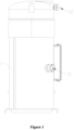
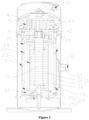
- a scroll compressor is provided according to the present disclosure, which includes at least an outer shell 1, an inner shell 2, a motor 3, and a scroll assembly 4.
- the outer shell 1 is provided with a gas inlet 11, and it is appreciated that the outer shell 1 is further provided with a gas outlet 12 for compressed refrigerant gas to be discharged from the scroll compressor, as shown in Figures 1 and 2 .
- the inner shell 2 is provided in the outer shell 1 and is configured for mounting various structures required for the scroll compressor.
- the motor 3 is arranged in the inner shell 2 and includes a stator 31 and a rotor 32 arranged in the stator 31. It is appreciated that the motor 3 may further include an upper wire wrap 33 and a lower wire wrap 34, the upper wire wrap 33 and the lower wire wrap 34 are used for driving the rotor 32 to rotate relative to the stator 31 once an electric current is inputted.
- the compression chamber 41 for compressing the refrigerant gas is formed in the scroll assembly 4 and is configured to compress the refrigerant gas under control of the motor 3.
- the rotor 32 is provided with a rotation shaft 35
- the scroll assembly 4 may include a movable scroll member 42 and a stationary scroll member 43 arranged in the compression chamber 41, the movable scroll member 42 is connected to the rotation shaft 35 via an eccentric shaft, and the rotation shaft 35 can drive the movable scroll member 42 to perform a rotary translation relative to the stationary scroll member 43.
- Both the movable scroll member 42 and the stationary scroll member 43 have helical profiles, and the movable scroll member 42 is mounted eccentrically with respect to the stationary scroll member 43 and contacts the stationary scroll member 43 in several straight lines in the axial direction, so that a series of crescent-shaped spaces, i.e., primitive volumes, are formed by the movable scroll member 42 and the stationary scroll member 43.
- the movable scroll member 42 takes a center of the stationary scroll member 43 as a rotation center, and performs the rotary translation without revolution with a certain rotation radius, the outer crescent-shaped spaces will continually move toward the center, thus the refrigerant gas is gradually pushed to the center region, with its volume constantly shrinking and the pressure continually increasing until reaching the center exhaust hole and being discharged from the exhaust hole on the outer shell 1.
- the upper chamber 21 is formed in the inner shell 2 between the motor 3 and the scroll assembly 4, and an air gap 23 is provided between the stator 31 and the rotor 32 and/or between the stator 31 and the inner shell 2, and the air gap 23 is in communication with the upper chamber 21, so that the refrigerant gas can enter the upper chamber 21 from the air gap 23.
- the stator 31 since the rotor 32 rotates relative to the stator 31 during the operation of the motor 3, it is inevitably necessary to reserve a gap between the stator 31 and the rotor 32, which can be used as the air gap 23.
- the stator 31 In a case that the stator 31 is arranged on the inner side of the inner shell 2, the stator 31 may be tightly fitted with the inner side of the inner shell 2, and there may also be a gap there between. In a case that there is a gap running up and down between the stator 31 and the inner side of the inner shell 2, the gap may also serve as an air gap.
- an upper inlet hole 24 is provided in the upper chamber 21.
- the temperature of the refrigerant gas entering from the gas inlet 11 is lower than the temperature of the motor 3, and the refrigerant gas entering from the gas inlet 11 is configured to enter the compression chamber 41 partly from the upper inlet hole 24 and partly from the air gap 23 to absorb the heat of the motor 3.
- the refrigerant gas may enter into the outer shell 1 from the gas inlet 11, and a part of the refrigerant gas may enter into the upper chamber 21 from the upper inlet hole 24, and another part of the refrigerant gas may enter the upper chamber 21 from the air gap, and the refrigerant gas in the upper chamber 21 may enter into the compression chamber 41 of the scroll assembly 4 to be compressed and discharged from the scroll compressor.
- the refrigerant gas can cool the motor 3 when passing through the air gap 23, so that the heat of the motor 3 can be effectively discharged and the temperature of the motor 3 can be decreased, which can in turn prolong the service life of the motor 3.
- the scroll compressor of the present disclosure has a simple air guiding structure, less manufacturing difficulty, and lower processing costs.
- the scroll compressor of the present disclosure further includes a main bearing housing 5.
- the main bearing housing 5 is arranged between the motor 3 and the scroll assembly 4 and is configured to support the scroll assembly 4.
- the main bearing housing 5 is provided with an inlet passage, and the refrigerant gas is configured to enter the compression chamber 41 through the inlet passage.
- the refrigerant gas entering the upper chamber 21 enters the compression chamber 41 of the scroll assembly 4 through the inlet passage on the main bearing housing 5.
- a lower chamber 22 is formed in the inner shell 2 on the side of the motor 3 away from the scroll assembly 4, and the lower chamber 22 is provided with the lower ventilation hole 25, the lower ventilation hole 25 includes a lower inlet hole 251 and a lower outlet hole 252, and the refrigerant gas entering from the gas inlet 11 is configured to at least partially enter the lower inlet hole 251.
- the lower outlet hole 252 is connected to the upper inlet hole 24 through a gap between the inner shell 2 and the outer shell 1.
- the refrigerant gas entering from the gas inlet 11 enters at least partially into the lower inlet hole 251 and thereby enters into the lower chamber 22, and then the refrigerant gas in the lower chamber 22 flows partially from the air gap 23 into the upper chamber 21, and partially flows out from the lower outlet hole 252 and then flows into the upper chamber 21 through the gap between the inner shell 2 and the outer shell 1.
- a part of the refrigerant gas enters the lower chamber 22 and is diverged in the lower chamber 22, a part of which flows into the air gap 23, and another part of which flows out of the lower outlet hole 252 of the lower chamber 22, so that the amount of refrigerant gas flowing into the air gap can be guaranteed, so as to ensure that the motor 3 can be sufficiently cooled, and to avoid the occurrence of a situation in which the temperature of the motor 3 is too high or even burned out.
- the excess refrigerant gas may flow out of the lower outlet hole 252 and flow into the upper chamber 21 through the gap between the inner shell 2 and the outer shell 1, thereby reducing the power loss of the refrigerant gas when flowing in the air gap 23, thus reducing the suction resistance of the scroll compressor.
- the refrigerant gas in the upper chamber 21 is configured to cool the upper wire wrap 33
- the refrigerant gas in the upper chamber 21 includes refrigerant gas entering the upper chamber 21 from the gas inlet 11 via the lower chamber 22 and the air gap 23, refrigerant gas entering the upper chamber 21 from the gas inlet 11 via the upper inlet hole 24, and refrigerant gas entering the upper chamber 21 from the gas inlet 11 via the lower chamber 22, the lower ventilation hole 25, and the upper inlet hole 24.
- the refrigerant gas in the lower chamber 22 is configured to cool the lower wire wrap 34.
- the refrigerant gas in the upper chamber 21 includes two parts, one part is from the air gap 23 and the other part is from the upper inlet hole 24, and the refrigerant gas from the upper inlet hole 24 may be divided into two parts, one part of which enters the upper inlet hole 24 directly from the gas inlet 11, and the other part of which enters the lower chamber 22 from the gas inlet 11, and flows from the lower ventilation hole 25 to the gap between the inner shell 2 and the outer shell 1, and enters the lower chamber 22 from the upper inlet hole 24.
- the refrigerant gas entering from the gas inlet 11 is configured to partially enter the lower inlet hole 251, and partially flow directly from the lower outlet hole 252 and the upper inlet hole 24 to the upper chamber 21 through the gap between the inner shell 2 and the outer shell 1.
- the lower wire wrap 34 can be efficiently cooled, preventing the lower wire wrap 34 from overheating.
- the refrigerant gas entering from the gas inlet 11 is configured to all enter the lower inlet hole 251.
- the refrigerant gas entering from the gas inlet 11 all enters the lower inlet hole 251, and thus enters the lower chamber 22, and then the refrigerant gas in the lower chamber 22 partly flows from the air gap 23 to the upper chamber 21, and partly flows from the lower outlet hole 23 to the upper chamber 21 through the gap between the inner shell 2 and the outer shell 1.
- the excess refrigerant gas may flow out of the lower outlet hole 252 and flow into the upper chamber 21 through the gap between the inner shell 2 and the outer shell 1, thereby reducing the power loss of the refrigerant gas when flowing in the air gap 23, thus reducing the suction resistance of the scroll compressor.
- the scroll compressor of the present disclosure further includes an air guiding portion 26, the air guiding portion 26 is arranged on the inner shell 2 and is connected to the lower inlet hole 251 at one end, and the opening at the other end directly faces the export of the gas inlet 11.
- the opening of the air guiding portion 26 directly faces the outlet of the gas inlet 11, when the refrigerant gas flows into the outer shell 1 from the gas inlet 11, a part of the refrigerant gas will enter into the opening of the air guiding portion 26, and thus flow from the lower inlet hole 251 to the lower chamber 22 along the air guiding portion 26.
- one end of the air guiding portion 26 is connected to the lower inlet hole 251, and the opening at the other end is connected to the export of the gas inlet 11, which also enables that after the refrigerant gas flows into the outer shell 1 from the gas inlet 11, a part of the refrigerant gas enters the opening of the air guiding portion 26.
- the air guiding portion 26 may also be arranged on the outer shell 1, with one end connected to the gas inlet 11 and the opening at the other end connected to the lower inlet hole 251, in a similar principle, which will not be repeated herein.
- the diameter of the opening of the air guiding portion 26 is larger than the diameter of the gas inlet 11. Since the diameter of the opening of the air guiding portion 26 is larger than the diameter of the export of the gas inlet 11, and the opening of the air guiding portion 26 directly faces the export of the inlet 11, so that during the operation of the scroll compressor of the present disclosure, a large portion of the refrigerant gas flowing out of the export of the gas inlet 11 will enter into the air guiding portion 26, so as to ensure that the refrigerant gases entering into the lower chamber 22 can efficiently cool the lower wire wrap 34, and to avoid an overheating of the lower wire wrap 34.
- the air guiding portion 26 is arranged on the inner shell 2, the entry of the air guiding portion 26 directly faces the opening of the outer shell 1, and the spacing between the outer contour of the air guiding portion 26 and the inner surface of the outer shell 1 is from 2 to 15 mm.
- the spacing between the outer contour of the air guiding portion 26 and the inner surface of the outer shell 1 is greater than or equal to 2 mm, the assembly accuracy between the air guiding portion 26 and the outer shell 1 can be effectively ensured, preventing contact between the outer contour of the air guiding portion 26 and the inner surface of the outer shell 1.
- the spacing between the outer contour of the air guiding portion 26 and the inner surface of the outer shell 1 is less than or equal to 15 mm, it can be ensured that a large amount of refrigerant gas will not enter the upper inlet hole 24 through the gap between the air guiding portion 26 and the inner surface of the outer shell 1, so as to ensure the cooling effect of the motor 3.
- the spacing between the outer contour of the air guiding portion 26 and the inner surface of the outer shell 1 is 5 mm, so as to effectively improve the cooling effect of the motor 3 and ensure the assembly accuracy between the air guiding portion 26 and the outer shell 1.
- the spacing between the outer contour of the air guiding portion 26 and the inner surface of the outer shell 1 is 5 mm, and in other embodiments, the spacing between the outer contour of the air guiding portion 26 and the inner surface of the outer shell 1 may also be set as needed, which is not limited herein.
- the scroll compressor of the present disclosure further includes an air guiding portion 26, and the air guiding portion 26 is configured so that the two ends are connected to the gas inlet 11, and the lower inlet hole 251, respectively.
- the refrigerant gas entering from the gas inlet 11 can all enter the lower inlet hole 251 along the air guiding portion 26, and thus enter into the lower chamber 22, and then the refrigerant gas in the lower chamber 22 flows partly from the air gap 23 into the upper chamber 21, and partly flows from the lower outlet hole 252 into the upper chamber 21 through the gap between the inner shell 2 and the outer shell 1.
- a sum of the areas of the upper inlet holes 24 is set to be less than a sum of the areas of the lower outlet holes 252.
- the ratio between the area of the upper inlet hole 24 and the area of the lower outlet hole 252 can be set so that the amount of refrigerant gas flowing to the air gap 23 is neither too much nor too little, so that the motor 3 can be effectively cooled without excessive power loss of the refrigerant gas.
- the number of the upper inlet hole 24 is larger than the number of the lower outlet hole 252, and the area of each upper inlet hole 24 is smaller than the area of the lower outlet hole 252.
- the refrigerant gas flowing out of the lower outlet hole 252 can enter into the upper chamber 21 from multiple upper inlet holes 24, so as to make the refrigerant gas more uniformly distributed when flowing in the gap between the inner shell 2 and the outer shell 1.
- the cooling effect of the motor 3 and the suction loss of the scroll compressor can be balanced by adjusting the area and number of the upper inlet hole 24, the structure is simple and the processing cost is relatively low.
- the upper inlet hole 24 and the lower ventilation hole 25 are configured to be uniformly distributed along the circumferential direction of the inner shell 2. Since the upper inlet hole 24 and lower ventilation hole 25 are uniformly distributed along the circumferential direction of the inner shell 2, the distances from lower outlet holes 252 to respective upper inlet holes 24 are relatively similar to each other, and the refrigerant gas can be distributed evenly in the circumferential direction of the inner shell 2, without excessive amount of gas on one side.
Landscapes
- Engineering & Computer Science (AREA)
- Mechanical Engineering (AREA)
- General Engineering & Computer Science (AREA)
- Applications Or Details Of Rotary Compressors (AREA)
- Rotary Pumps (AREA)
Applications Claiming Priority (2)
| Application Number | Priority Date | Filing Date | Title |
|---|---|---|---|
| CN202311278617.5A CN117189614B (zh) | 2023-09-28 | 2023-09-28 | 涡旋压缩机 |
| PCT/CN2024/085338 WO2025066078A1 (zh) | 2023-09-28 | 2024-04-01 | 涡旋压缩机 |
Publications (2)
| Publication Number | Publication Date |
|---|---|
| EP4556715A1 true EP4556715A1 (de) | 2025-05-21 |
| EP4556715A4 EP4556715A4 (de) | 2025-11-19 |
Family
ID=89005270
Family Applications (1)
| Application Number | Title | Priority Date | Filing Date |
|---|---|---|---|
| EP24826859.1A Pending EP4556715A4 (de) | 2023-09-28 | 2024-04-01 | Spiralverdichter |
Country Status (4)
| Country | Link |
|---|---|
| US (1) | US20260002537A1 (de) |
| EP (1) | EP4556715A4 (de) |
| CN (1) | CN117189614B (de) |
| WO (1) | WO2025066078A1 (de) |
Families Citing this family (1)
| Publication number | Priority date | Publication date | Assignee | Title |
|---|---|---|---|---|
| CN117189614B (zh) * | 2023-09-28 | 2025-05-06 | 比泽尔制冷技术(中国)有限公司 | 涡旋压缩机 |
Family Cites Families (12)
| Publication number | Priority date | Publication date | Assignee | Title |
|---|---|---|---|---|
| US5533875A (en) * | 1995-04-07 | 1996-07-09 | American Standard Inc. | Scroll compressor having a frame and open sleeve for controlling gas and lubricant flow |
| DE10065821A1 (de) * | 2000-12-22 | 2002-07-11 | Bitzer Kuehlmaschinenbau Gmbh | Kompressor |
| FR2830292B1 (fr) * | 2001-09-28 | 2003-12-19 | Danfoss Maneurop S A | Circuit de gaz basse pression pour un compresseur |
| US7311501B2 (en) * | 2003-02-27 | 2007-12-25 | American Standard International Inc. | Scroll compressor with bifurcated flow pattern |
| FR2885966B1 (fr) * | 2005-05-23 | 2011-01-14 | Danfoss Commercial Compressors | Compresseur frigorifique a spirales |
| FR2989433B1 (fr) * | 2012-04-16 | 2018-10-12 | Danfoss Commercial Compressors | Compresseur a spirales |
| FR2998340A1 (fr) * | 2012-11-19 | 2014-05-23 | Danfoss Commercial Compressors | Compresseur a spirale a vitesse variable. |
| FR3067412B1 (fr) * | 2017-06-13 | 2019-07-19 | Danfoss Commercial Compressors | Compresseur a spirales muni d'un dispositif de deviation et de division de fluide |
| CN114593057B (zh) * | 2022-03-14 | 2025-11-18 | 冰山松洋压缩机(大连)有限公司 | 一种涡旋压缩机 |
| CN217233797U (zh) * | 2022-03-14 | 2022-08-19 | 松下压缩机(大连)有限公司 | 一种涡旋压缩机 |
| CN117189614B (zh) * | 2023-09-28 | 2025-05-06 | 比泽尔制冷技术(中国)有限公司 | 涡旋压缩机 |
| CN220909988U (zh) * | 2023-09-28 | 2024-05-07 | 比泽尔制冷技术(中国)有限公司 | 涡旋压缩机 |
-
2023
- 2023-09-28 CN CN202311278617.5A patent/CN117189614B/zh active Active
-
2024
- 2024-04-01 EP EP24826859.1A patent/EP4556715A4/de active Pending
- 2024-04-01 WO PCT/CN2024/085338 patent/WO2025066078A1/zh active Pending
- 2024-04-01 US US18/880,120 patent/US20260002537A1/en active Pending
Also Published As
| Publication number | Publication date |
|---|---|
| US20260002537A1 (en) | 2026-01-01 |
| EP4556715A4 (de) | 2025-11-19 |
| CN117189614A (zh) | 2023-12-08 |
| WO2025066078A1 (zh) | 2025-04-03 |
| CN117189614B (zh) | 2025-05-06 |
Similar Documents
| Publication | Publication Date | Title |
|---|---|---|
| US7226280B1 (en) | Roots vacuum pump | |
| EP2980409A1 (de) | Spiralströmungsmaschine | |
| EP4556715A1 (de) | Spiralverdichter | |
| CN114001027A (zh) | 泵体组件及增焓转子压缩机 | |
| CN109185128B (zh) | 一种涡旋空气压缩机 | |
| WO2023098102A1 (zh) | 压缩机转子、压缩机泵体、压缩机及温度调节系统 | |
| WO2011072617A1 (zh) | 全封闭式制冷压缩机及其转子压缩机单元 | |
| CN103511275A (zh) | 低背压旋转式压缩机 | |
| CN220909988U (zh) | 涡旋压缩机 | |
| CN211116580U (zh) | 压缩机涡盘结构及应用该结构的半封闭式涡旋压缩机 | |
| CN117189598A (zh) | 压缩机及制冷设备 | |
| CN215292888U (zh) | 旋转式压缩机 | |
| CN216381861U (zh) | 泵体组件及增焓转子压缩机 | |
| CN115898878A (zh) | 泵体组件、滚动转子式压缩机、空调器 | |
| JP5363486B2 (ja) | ロータリ圧縮機 | |
| CN220909989U (zh) | 涡旋压缩机 | |
| WO2025044627A1 (zh) | 浮动式无油真空涡旋压缩机 | |
| CN218522812U (zh) | 一种单吸气压缩机的泵体结构、压缩机和空调器 | |
| CN215256803U (zh) | 旋转式压缩机 | |
| CN215409201U (zh) | 泵体及压缩机 | |
| CN215927779U (zh) | 涡旋压缩机及具有其的制冷设备 | |
| CN105570135A (zh) | 一种直连式回转压缩机 | |
| CN117189601A (zh) | 泵体组件、压缩机及制冷设备 | |
| CN211422947U (zh) | 压缩机构及具有其的压缩机 | |
| CN115559910A (zh) | 一种单吸气压缩机的泵体结构、压缩机和空调器 |
Legal Events
| Date | Code | Title | Description |
|---|---|---|---|
| STAA | Information on the status of an ep patent application or granted ep patent |
Free format text: STATUS: UNKNOWN |
|
| STAA | Information on the status of an ep patent application or granted ep patent |
Free format text: STATUS: THE INTERNATIONAL PUBLICATION HAS BEEN MADE |
|
| PUAI | Public reference made under article 153(3) epc to a published international application that has entered the european phase |
Free format text: ORIGINAL CODE: 0009012 |
|
| STAA | Information on the status of an ep patent application or granted ep patent |
Free format text: STATUS: REQUEST FOR EXAMINATION WAS MADE |
|
| 17P | Request for examination filed |
Effective date: 20241230 |
|
| AK | Designated contracting states |
Kind code of ref document: A1 Designated state(s): AL AT BE BG CH CY CZ DE DK EE ES FI FR GB GR HR HU IE IS IT LI LT LU LV MC ME MK MT NL NO PL PT RO RS SE SI SK SM TR |
|
| A4 | Supplementary search report drawn up and despatched |
Effective date: 20251017 |
|
| RIC1 | Information provided on ipc code assigned before grant |
Ipc: F04C 18/02 20060101AFI20251013BHEP Ipc: F04C 29/04 20060101ALI20251013BHEP Ipc: F04C 29/12 20060101ALI20251013BHEP Ipc: F04C 23/00 20060101ALI20251013BHEP |