EP4556352A1 - Fahrzeugkarosseriestruktur und herstellungsverfahren dafür sowie fahrzeug - Google Patents
Fahrzeugkarosseriestruktur und herstellungsverfahren dafür sowie fahrzeug Download PDFInfo
- Publication number
- EP4556352A1 EP4556352A1 EP23939210.3A EP23939210A EP4556352A1 EP 4556352 A1 EP4556352 A1 EP 4556352A1 EP 23939210 A EP23939210 A EP 23939210A EP 4556352 A1 EP4556352 A1 EP 4556352A1
- Authority
- EP
- European Patent Office
- Prior art keywords
- panel
- side wall
- pillar
- inner panel
- outer panel
- Prior art date
- Legal status (The legal status is an assumption and is not a legal conclusion. Google has not performed a legal analysis and makes no representation as to the accuracy of the status listed.)
- Pending
Links
Images


Classifications
-
- B—PERFORMING OPERATIONS; TRANSPORTING
- B62—LAND VEHICLES FOR TRAVELLING OTHERWISE THAN ON RAILS
- B62D—MOTOR VEHICLES; TRAILERS
- B62D25/00—Superstructure or monocoque structure sub-units; Parts or details thereof not otherwise provided for
- B62D25/02—Side panels
-
- B—PERFORMING OPERATIONS; TRANSPORTING
- B62—LAND VEHICLES FOR TRAVELLING OTHERWISE THAN ON RAILS
- B62D—MOTOR VEHICLES; TRAILERS
- B62D25/00—Superstructure or monocoque structure sub-units; Parts or details thereof not otherwise provided for
- B62D25/02—Side panels
- B62D25/025—Side sills thereof
-
- B—PERFORMING OPERATIONS; TRANSPORTING
- B62—LAND VEHICLES FOR TRAVELLING OTHERWISE THAN ON RAILS
- B62D—MOTOR VEHICLES; TRAILERS
- B62D25/00—Superstructure or monocoque structure sub-units; Parts or details thereof not otherwise provided for
- B62D25/08—Front or rear portions
-
- B—PERFORMING OPERATIONS; TRANSPORTING
- B62—LAND VEHICLES FOR TRAVELLING OTHERWISE THAN ON RAILS
- B62D—MOTOR VEHICLES; TRAILERS
- B62D25/00—Superstructure or monocoque structure sub-units; Parts or details thereof not otherwise provided for
- B62D25/08—Front or rear portions
- B62D25/088—Details of structures as upper supports for springs or dampers
-
- B—PERFORMING OPERATIONS; TRANSPORTING
- B62—LAND VEHICLES FOR TRAVELLING OTHERWISE THAN ON RAILS
- B62D—MOTOR VEHICLES; TRAILERS
- B62D25/00—Superstructure or monocoque structure sub-units; Parts or details thereof not otherwise provided for
- B62D25/20—Floors or bottom sub-units
-
- B—PERFORMING OPERATIONS; TRANSPORTING
- B62—LAND VEHICLES FOR TRAVELLING OTHERWISE THAN ON RAILS
- B62D—MOTOR VEHICLES; TRAILERS
- B62D65/00—Designing, manufacturing, e.g. assembling, facilitating disassembly, or structurally modifying motor vehicles or trailers, not otherwise provided for
- B62D65/02—Joining sub-units or components to, or positioning sub-units or components with respect to, body shell or other sub-units or components
-
- B—PERFORMING OPERATIONS; TRANSPORTING
- B62—LAND VEHICLES FOR TRAVELLING OTHERWISE THAN ON RAILS
- B62D—MOTOR VEHICLES; TRAILERS
- B62D25/00—Superstructure or monocoque structure sub-units; Parts or details thereof not otherwise provided for
- B62D25/08—Front or rear portions
- B62D25/082—Engine compartments
-
- Y—GENERAL TAGGING OF NEW TECHNOLOGICAL DEVELOPMENTS; GENERAL TAGGING OF CROSS-SECTIONAL TECHNOLOGIES SPANNING OVER SEVERAL SECTIONS OF THE IPC; TECHNICAL SUBJECTS COVERED BY FORMER USPC CROSS-REFERENCE ART COLLECTIONS [XRACs] AND DIGESTS
- Y02—TECHNOLOGIES OR APPLICATIONS FOR MITIGATION OR ADAPTATION AGAINST CLIMATE CHANGE
- Y02T—CLIMATE CHANGE MITIGATION TECHNOLOGIES RELATED TO TRANSPORTATION
- Y02T10/00—Road transport of goods or passengers
- Y02T10/10—Internal combustion engine [ICE] based vehicles
- Y02T10/40—Engine management systems
Definitions
- the present invention relates to the field of vehicle body structure technologies, and in particular, to a vehicle body structure and a manufacturing method therefor, and a vehicle.
- a conventional vehicle body is made up of hundreds of parts that are welded through a plurality of processes. Individual parts are welded to form subassemblies. Subassemblies are welded to form assemblies, that is, to form several major assemblies such as a front engine compartment welding assembly, a front floor welding assembly, a rear floor welding assembly, a side wall welding assembly, and a top cover welding assembly. Finally, these several major assemblies are combined on a main line to form a vehicle body-in-white assembly. In a production process, additional reinforcing panels further need to be arranged on individual parts, resulting in a quantity of more than 500 individual parts. In addition, thousands of dies and hundreds of fixtures are required for welding through more than 6,000 solder joints.
- a first objective of the present invention is to provide a vehicle body structure, so as to resolve a problem in a conventional technology that the vehicle body structure integrates an excessively large quantity of parts.
- a second objective of the present invention is to provide a manufacturing method for a vehicle body structure.
- a third objective of the present invention is to provide a vehicle.
- a vehicle body structure is provided.
- the vehicle body structure is characterized by including:
- each of the left side wall inner panel and the right side wall inner panel is formed through hot stamping of an integrated sheet having two closed door rings; and each of the left side wall inner panel and the right side wall inner panel includes:
- an inner panel B-pillar patch panel is disposed in an upper portion of the inner panel B-pillar portion, and the inner panel B-pillar patch panel is integrally molded with the integrated sheet through hot stamping.
- each of the left side wall outer panel reinforcing panel and the right side wall outer panel reinforcing panel is formed through hot stamping of an integrated sheet having two closed door rings; and each of the left side wall outer panel reinforcing panel and the right side wall outer panel reinforcing panel includes:
- each of the left side wall outer panel reinforcing panel and the right side wall outer panel reinforcing panel further includes an outer panel A-pillar upper patch panel and an outer panel A-pillar lower patch panel;
- the outer panel A-pillar upper patch panel starts from the outer panel A-pillar upper end portion and extends along the first outer panel upper side beam portion to the outer panel B-pillar upper end portion, and the outer panel A-pillar upper patch panel is integrally molded with the integrated sheet through hot stamping;
- the outer panel A-pillar lower patch panel is disposed in the outer panel A-pillar portion and located between the outer panel A-pillar upper end portion and the outer panel A-pillar lower end portion, and the outer panel A-pillar lower patch panel is integrally molded with the integrated sheet through hot stamping.
- a flange connection surface is disposed on each of outer edges of the left side wall outer panel reinforcing panel and the right side wall outer panel reinforcing panel, and inner edges of the first outer closed door ring and the second outer closed door ring;
- a flange connection surface is disposed on each of outer edges of the left side wall inner panel and the right side wall inner panel, and inner edges of the first inner closed door ring and the second inner closed door ring;
- the left side wall outer panel reinforcing panel is connected to the left side wall inner panel through the flange connection surface
- the right side wall outer panel reinforcing panel is connected to the right side wall inner panel through the flange connection surface.
- each of cross sections of the left front longitudinal beam section of the engine compartment framework and the right front longitudinal beam section of the engine compartment framework is of an upwardly open "U"-shaped force transmission structure.
- a front longitudinal beam sealing panel is disposed at each of the upward openings of the left front longitudinal beam section of the engine compartment framework and the right front longitudinal beam section of the engine compartment framework.
- the engine compartment framework further includes a first engine compartment patch panel and a second engine compartment patch panel, and the first engine compartment patch panel and the second engine compartment patch panel are disposed in the rear section of the engine compartment framework and integrally molded with the integral sheet material through stamping.
- the front wall panel includes a front wall panel upper panel portion, a front wall panel lower panel portion, and a reinforcing beam portion located between the front wall panel upper panel portion and the front wall panel lower panel portion, and a cavity with a triangular cross section is formed between a footrest position of the front wall panel lower panel portion and the rear section of the engine compartment framework.
- the front wall panel further includes a first front wall patch panel and a second front wall patch panel
- the first front wall patch panel is disposed in a left part of the front wall panel upper panel portion and overlaps downward with the reinforcing beam portion
- the second front wall patch panel is disposed in a middle of the front wall panel lower panel portion and overlaps upward with the reinforcing beam portion
- the first front wall patch panel and the second front wall patch panel are integrally molded with an integral sheet material of the front wall panel through hot stamping.
- the rear floor framework includes a left side beam portion, a right side beam portion, and a front transverse beam portion, a middle transverse beam portion, and a rear transverse beam portion that are located between the left side beam portion and the right side beam portion, where the front transverse beam portion is closed and connected to front ends of the left side beam portion and the right side beam portion, the rear transverse beam portion is disposed close to rear ends of the left side beam portion and the right side beam portion, and the middle transverse beam portion is located between the front transverse beam portion and the rear transverse beam portion.
- each of the left rear wheel cover and the right rear wheel cover includes a rear wheel cover outer panel and a rear wheel cover inner panel, a first overlap edge and a second overlap edge for connection to the left-right side wall inner panel are disposed in a front portion of the rear wheel cover inner panel, a third overlap edge that overlaps with a D-pillar is disposed on an upper edge of the rear wheel cover inner panel, a fourth overlap edge that overlaps with the rear wheel cover outer panel is disposed in a rear portion of the rear wheel cover inner panel, and a fifth overlap edge that overlaps with the rear floor framework is disposed in a lower portion of the rear wheel cover inner panel.
- a flange is correspondingly disposed in each of an outer panel C-pillar portion of the left-right side wall outer panel reinforcing panel and an inner panel C-pillar portion of the left-right side wall inner panel, the flange of the inner panel C-pillar portion overlaps with the first overlap edge of the rear wheel cover inner panel and the rear wheel cover outer panel, the flange of the outer panel C-pillar portion overlaps with a panel surface of the rear wheel cover outer panel, and a cavity structure with a closed cross section is formed in the outer panel C-pillar portion and the inner panel C-pillar portion.
- each of the left front wheel cover and the right front wheel cover includes a shock absorber mounting portion, a wheel cover portion, a wheel cover rear reinforcing portion, a wheel cover front reinforcing portion, a first front wheel cover patch panel, and a second front wheel cover patch panel; the first front wheel cover patch panel is attached to inner sides of the shock absorber mounting portion and the wheel cover portion, and the second front wheel cover patch panel is attached to the inner side of the wheel cover portion.
- a manufacturing method for a vehicle body structure is provided.
- the method is characterized by including the following steps:
- a vehicle is provided.
- the vehicle is characterized by including the vehicle body structure according to any implementation of the first aspect.
- each individual part of a vehicle body structure is integrated into an integral sheet material, then hot stamping is performed on the integral sheet material to form an integrated part, and finally various integrated parts are welded to form a highly integrated vehicle body structure.
- Conventional welding of a plurality of parts through a plurality of processes and a plurality of solder joints is replaced with simple welding of several integrally molded hot-stamped parts. This avoids a matching quality problem caused by a part size error, avoids collision performance difference caused by a status consistency difference of a plurality of parts, and reduces a quantity of solder joints, thereby reducing a probability of solder joint failure, and further improving collision stability and improving overall vehicle safety.
- the figures provided in the following embodiments merely schematically describe the basic concept of the present invention. Therefore, the figures display only components related to the present invention instead of being drawn based on a quantity, shapes, and sizes of components in actual implementation. Forms, the quantity, and a ratio of the components in actual implementation of the figures may be randomly changed, and a component layout form of the figures may also be more complex.
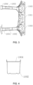
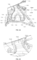
- FIG. 1 is a schematic structural diagram of a vehicle body structure according to an example embodiment of the present invention.
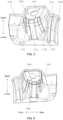
- FIG. 2 is a three-dimensional diagram of a vehicle body structure according to an example embodiment of the present invention.
- this example embodiment provides a vehicle body structure, which includes a left-right side wall inner panel, a left-right side wall outer panel reinforcing panel, an engine compartment framework 1000, a left-right front wheel cover, a front wall panel 3000, a rear floor framework 6000, and a left-right rear wheel cover.
- the left-right side wall inner panel includes a left side wall inner panel 4000L and a right side wall inner panel 4000R that are integrally molded through hot stamping of an integral sheet material, where the left side wall inner panel 4000L and the right side wall inner panel 4000R are symmetrically and respectively disposed on two sides.
- the left-right side wall outer panel reinforcing panel includes a left side wall outer panel reinforcing panel 5000L and a right side wall outer panel reinforcing panel 5000R that are integrally molded through hot stamping of an integral sheet material, where the left side wall outer panel reinforcing panel 5000L and the right side wall outer panel reinforcing panel 5000R are symmetrically and respectively disposed on two sides, the left side wall outer panel reinforcing panel 5000L is disposed on an outer side of the left side wall inner panel 4000L, and the right side wall outer panel reinforcing panel 5000R is disposed on an outer side of the right side wall inner panel 4000R.
- the engine compartment framework 1000 is disposed between the left side wall inner panel 4000L and the right side wall inner panel 4000R, and is located in a front section of the left-right side wall inner panel, where the engine compartment framework 1000 includes a left front longitudinal beam section 1002 of the engine compartment framework, a right front longitudinal beam section 1003 of the engine compartment framework, and a rear section 1001 of the engine compartment framework that are combined and integrally molded through hot stamping of an integral sheet material.
- the left-right front wheel cover includes a left front wheel cover 2000L and a right front wheel cover 2000R that are integrally molded through hot stamping of an integral sheet material, where the left front wheel cover 2000L and the right front wheel cover 2000R are respectively disposed on two sides of the engine compartment framework 1000.
- the front wall panel 3000 is integrally molded through hot stamping of an integral sheet material, is disposed in the rear section 1001 of the engine compartment framework, and is located between the left side wall inner panel 4000L and the right side wall inner panel 4000R.
- the rear floor framework 6000 is integrally molded through hot stamping of an integral sheet material, is disposed between the left side wall inner panel 4000L and the right side wall inner panel 4000R, and is located in a rear section of the left-right side wall inner panel.
- the left-right rear wheel cover includes a left rear wheel cover 7000L and a right rear wheel cover 7000R that are integrally molded through hot stamping of an integral sheet material, where the left rear wheel cover 7000L and the right rear wheel cover 7000R are respectively disposed on two sides of the rear floor framework 6000.
- each of the left side wall inner panel 4000L and the right side wall inner panel 4000R is formed through hot stamping of an integrated sheet having two closed door rings; and each of the left side wall inner panel 4000L and the right side wall inner panel 4000R includes: an inner panel A-pillar portion 4200, an inner panel B-pillar portion 4300, an inner panel C-pillar portion 4500, an inner panel doorsill portion 4600, a first inner panel upper side beam portion 4100, and a second inner panel upper side beam portion 4400.
- the inner panel A-pillar portion 4200 includes an inner panel A-pillar upper end portion and an inner panel A-pillar lower end portion.
- the inner panel B-pillar portion 4300 includes an inner panel B-pillar upper end portion and an inner panel B-pillar lower end portion.
- the inner panel C-pillar portion 4500 includes an inner panel C-pillar upper end portion and an inner panel C-pillar lower end portion.
- the inner panel doorsill portion 4600 is located between the inner panel A-pillar lower end portion and the inner panel C-pillar lower end portion, where the inner panel B-pillar lower end portion is connected to a middle of the inner panel doorsill portion 4600.
- the first inner panel upper side beam portion 4100 is located between the inner panel B-pillar upper end portion and the inner panel A-pillar upper end portion.
- the second inner panel upper side beam portion 4400 is located between the inner panel B-pillar upper end portion and the inner panel C-pillar upper end portion.
- the inner panel A-pillar portion 4200, the first inner panel upper side beam portion 4100, the inner panel B-pillar portion 4300, and the inner panel doorsill portion 4600 form a first inner closed door ring
- the inner panel C-pillar portion 4500, the second inner panel upper side beam portion 4400, the inner panel B-pillar portion 4300, and the inner panel doorsill portion 4600 form a second inner closed door ring
- the side wall inner panel integrates the inner panel A-pillar portion 4200 that is conventionally integrated into the engine compartment assembly, and integrates the inner panel doorsill portion 4600 that is conventionally integrated into the rear floor assembly, so that the side wall inner panel forms a closed and stable " "(rectangular-tri-glide)-shaped structure.
- the part of the side wall inner panel is highly integrated into a hot-stamped part, thereby greatly reducing a quantity of parts to be developed, and greatly reducing quantities of dies, inspection tools, and fixtures.
- reduction of production processes effectively improves precision of a side wall welding assembly, reduces production costs, implements lightweight requirements, and improves rigidity and frontal and lateral collision performance of a vehicle body, thereby fully ensuring that a degree of injury of passengers in the vehicle is reduced after the vehicle is passively impacted.
- a first inner panel reinforcing rib 4210 is disposed at a connection part between the inner panel A-pillar portion 4200 and the front finger beam 5910, and a second inner panel reinforcing rib 4220 in a straight tooth shape is further disposed at the inner panel A-pillar portion 4200.
- the first inner panel reinforcing rib 4210 transmits a positive force flow upward to the first inner panel upper side beam portion 4100 for force relief.
- a lower portion of the first inner panel reinforcing rib 4210 transmits a positive force flow downward to the second inner panel reinforcing rib 4220.
- the second inner panel reinforcing rib 4220 can rapidly disperse the positive force flow and transmit the positive force flow to a rear portion of the vehicle body.
- a curved third inner panel reinforcing rib 4510 is disposed on a rear end edge of the inner panel C-pillar portion 4500 and extends from top to bottom, and a flange 4520 used to overlap with the rear wheel cover is added to an edge of the third inner panel reinforcing rib 4510. This increases torsion rigidity of the entire vehicle, and improves comfort, maneuverability, and safety of driving.
- a fourth inner panel reinforcing rib 4610 is disposed on the inner panel doorsill portion 4600, and the fourth inner panel reinforcing rib 4610 is connected to the second inner panel reinforcing rib 4220 through penetration.
- an inner panel B-pillar patch panel 4310 is disposed in an upper portion of the inner panel B-pillar portion, and the inner panel B-pillar patch panel 4310 is integrally molded with the integrated sheet through hot stamping, thereby effectively enhancing protection for heads of a plurality of passengers.
- each of the left side wall outer panel reinforcing panel 5000L and the right side wall outer panel reinforcing panel 5000R is formed through hot stamping of an integrated sheet having two closed door rings.
- Each of the left side wall outer panel reinforcing panel 5000L and the right side wall outer panel reinforcing panel 5000R includes: an outer panel A-pillar portion 5100, an outer panel B-pillar portion 5300, an outer panel C-pillar portion 5500, an outer panel doorsill portion 5600, a first outer panel upper side beam portion 5200, and a second outer panel upper side beam portion 5400.
- the outer panel A-pillar portion 5100 includes an outer panel A-pillar upper end portion and an outer panel A-pillar lower end portion.
- the outer panel B-pillar portion 5300 includes an outer panel B-pillar upper end portion and an outer panel B-pillar lower end portion.
- the outer panel C-pillar portion 5500 includes an outer panel C-pillar upper end portion and an outer panel C-pillar lower end portion.
- the outer panel doorsill portion 5600 is located between the outer panel A-pillar lower end portion and the outer panel C-pillar lower end portion, where the outer panel B-pillar lower end portion is connected to a middle of the outer panel doorsill portion 5600.
- the first outer panel upper side beam portion 5200 is located between the outer panel B-pillar upper end portion and the outer panel A-pillar upper end portion.
- the second outer panel upper side beam portion 5400 is located between the outer panel B-pillar upper end portion and the outer panel C-pillar upper end portion.
- the outer panel A-pillar portion 5100, the first outer panel upper side beam portion 5200, the outer panel B-pillar portion 5300, and the outer panel doorsill portion 5600 form a first outer closed door ring, that is, a front door ring.
- the outer panel C-pillar portion 5500, the second outer panel upper side beam portion 5400, the outer panel B-pillar portion 5300, and the outer panel doorsill portion 5600 form a second outer closed door ring, that is, a rear door ring. In this way, a closed and stable rectangular-tri-glide -shaped structure is formed.
- an integrated continuous C-pillar structure is formed by integrating the second outer closed door ring, thereby effectively improving torsion performance of the entire vehicle and improving driving experience.
- each of the left side wall outer panel reinforcing panel 5000L and the right side wall outer panel reinforcing panel 5000R further includes an outer panel A-pillar upper patch panel 5016 and an outer panel A-pillar lower patch panel 5017;
- the outer panel A-pillar upper patch panel 5016 starts from the outer panel A-pillar upper end portion and extends along the first outer panel upper side beam portion 5200 to the outer panel B-pillar upper end portion, and the outer panel A-pillar upper patch panel 5016 is integrally molded with the integrated sheet through hot stamping;
- the outer panel A-pillar lower patch panel 5017 is disposed in the outer panel A-pillar portion 5100 and located between the outer panel A-pillar upper end portion and the outer panel A-pillar lower end portion, and the outer panel A-pillar lower patch panel 5017 is integrally molded with the integrated sheet through hot stamping.
- the disposing positions of the outer panel A-pillar upper patch panel 5016 and the outer panel A-pillar lower patch panel 5017 include but are not limited to the foregoing disposing positions, and may be properly distributed based on collision simulation analysis.
- a bending-resistant cross section formed by integrally molding the outer panel A-pillar upper patch panel 5016 and the entire first outer panel upper side beam portion 5200 is in a circular arch shape.
- the outer panel A-pillar upper patch panel 5016 can assist the first outer panel upper side beam in dispersing collision energy to the outer panel B-pillar portion 5300, so as to prevent the first outer panel upper side beam from bending and failing during force transmission.
- the outer panel A-pillar lower patch panel 5017 can assist the outer panel A-pillar portion 5100 in transmitting and dispersing the energy to the door anti-collision beam 5900 disposed on the door.
- a flange connection surface 5014 is disposed on each of outer edges of the left side wall outer panel reinforcing panel 5000L and the right side wall outer panel reinforcing panel 5000R, and inner edges of the first outer closed door ring and the second outer closed door ring; a flange connection surface 5014 is disposed on each of outer edges of the left side wall inner panel 4000L and the right side wall inner panel 4000R, and inner edges of the first inner closed door ring and the second inner closed door ring; the left side wall outer panel reinforcing panel 5000L is connected to the left side wall inner panel 4000L through the flange connection surface 5014, and the right side wall outer panel reinforcing panel 5000R is connected to the right side wall inner panel through the flange connection surface 5014.
- a width H7 of the flange connection surface 5014 is 10-25 mm, so as to prevent a problem of unqualified flatness caused by an excessively long flange surface. This effectively improves overall rigidity of the rear door ring and modality of the rear wheel cover, and improves driving experience of the user.
- the left-right side wall outer panel reinforcing panel is further designed as follows: First, after the side wall outer panel reinforcing panel is integrated with two door rings, a size of the part increases, and a stamping depth of the part increases, which usually exceeds a maximum demolding depth of the current hot-stamped device, increasing the molding difficulty. Therefore, the structure of two door rings needs to be adaptively designed. Details are as follows: Referring to FIG. 14 and FIG. 15 , the outer panel A-pillar lower end portion has a tip position, and a crack may occur at the tip position due to excessive material thinning.
- a tip position at a corner at which the outer panel A-pillar portion 5100 is connected to the outer panel doorsill portion 5600 is processed by using a C-angle to form a smoothly transitioned beveled surface 5007. Therefore, a resistance in forming the sheet material is reduced, bending fluidity of forming the sheet material is improved, and a molding depth of the tip position is reduced, thereby reducing the molding difficulty.
- a first corner 5008 is formed at a connection part between the outer panel A-pillar portion 5100 and the outer panel doorsill portion 5600
- a second corner 5009 is formed at a connection part between the outer panel B-pillar portion 5300 and the outer panel doorsill portion 5600.
- An inner round corner radius R1 of the first corner 5008 is greater than or equal to 2.5 times a hot stamping depth H1 at the first corner 5008, and an inner round corner radius R2 of the second corner 5009 is greater than or equal to 2.5 times a hot stamping depth H2 at the second corner 5009.
- a secondary stepped surface 5012 used to reduce a molding depth is disposed at the first corner 5008, and a secondary stepped surface 5012 used to reduce a molding depth is disposed at the second corner 5009.
- disposing of the stepped surface can reduce a molding depth of a corner region, meeting a requirement for a hot stamping depth.
- a third corner 5010 formed at a connection part between the outer panel C-pillar portion 5500 and the outer panel doorsill portion 5600, and a fourth corner 5011 formed at a connection part between the outer panel B-pillar portion 5300 and the outer panel doorsill portion 5600 need to meet the following parameter requirements:
- An inner round corner radius R3 of the third corner 5010 is greater than or equal to 2.5 times a hot stamping depth H3 at the third corner 5010
- an inner round corner radius R4 of the fourth corner 5011 is greater than or equal to 2.5 times a hot stamping depth H4 at the fourth corner 5011.
- a secondary stepped surface 5012 used to reduce a molding depth is disposed at the third corner 5010, and a secondary stepped surface 5012 used to reduce a molding depth is disposed at the fourth corner 5011.
- disposing of the stepped surface can reduce a molding depth of a corner region, meeting a requirement for a hot stamping depth.
- a corner radius R5 of a cross section formed by hot stamping of the outer panel doorsill portion 5600 is greater than or equal to 6 mm.
- a corner radius R6 of a cross section formed by hot stamping of the outer panel C-pillar portion 5500 is greater than or equal to 8 mm.
- the cross section of the outer panel C-pillar portion 5500 is in a stepped shape with two reverse corners; a flange 4520 connected to the rear wheel cover is disposed on an outer edge of the outer panel C-pillar portion 5500.
- a width H5 of the flange 4520 is 15-25 mm, so as to ensure that the flange 4520 is not wrinkled during molding of the flange 4520.
- a size of a lower portion of the outer panel C-pillar portion 5500 is small because the lower portion of the outer panel C-pillar portion 5500 is affected by a shape and tire envelopment. Therefore, a width H6 of the stepped surface of the outer panel C-pillar portion 5500 that is connected to the flange 4520 is greater than or equal to 30 mm, so as to ensure die strength.
- a continuous through rib 5015 is disposed on the outer panel doorsill portion 5600, the outer panel A-pillar portion 5100, and the first outer panel upper side beam portion 5200, so as to improve a bending resistance capability of a cross section. As shown in a in FIG.
- the through rib 5015 partially forms an "E"-shaped force transmission structure in the outer panel A-pillar portion 5100, and an anti-collision beam may be connected to the "E"-shaped force transmission structure.
- the "E"-shaped force transmission structure transmits and disperses a part of collision energy of the outer panel A-pillar portion 5100 through the anti-collision beam, so as to reduce force relief pressure in a direction of the outer panel A-pillar upper end portion and the first upper side beam, and force relief pressure in a direction of the outer panel A-pillar lower end portion and the outer panel doorsill portion 5600.
- a partial bending-resistant cross section formed by the through rib 5015 in the outer panel A-pillar portion 5100 is in a "n"(channel) shape, as shown in b in FIG. 19 .
- a partial bending-resistant cross section formed by the through rib 5015 in the outer panel doorsill portion 56004 is in a "" shape, as shown in c in FIG. 17 .
- the channel-shaped bending-resistant cross section can effectively improve the overall impact resistance performance of the vehicle body structure and ensure the safety of the driver.
- each of cross sections of the left front longitudinal beam section 1002 of the engine compartment framework and the right front longitudinal beam section 1003 of the engine compartment framework is of an upwardly open "U"-shaped force transmission structure.
- a front longitudinal beam sealing panel 1004 is disposed at each of the upward openings of the left front longitudinal beam section 1002 of the engine compartment framework and the right front longitudinal beam section 1003 of the engine compartment framework. Changing the opening of the conventional front longitudinal beam cross section from facing two sides to facing upward facilitates overall hot stamping in the same stamping direction at one single time, and makes the production more convenient as the front longitudinal beam sealing panel 1004 can be disposed along the stamping direction.
- the engine compartment framework 1000 further includes a first engine compartment patch panel 1005 and a second engine compartment patch panel 1006, and the first engine compartment patch panel 1005 and the second engine compartment patch panel 1006 are disposed in the rear section 1001 of the engine compartment framework and integrally molded with the integral sheet material through stamping.
- a first engine compartment patch panel 1005 and a second engine compartment patch panel 1006 are disposed in the rear section 1001 of the engine compartment framework and integrally molded with the integral sheet material through stamping.
- Three properly-defined zones are obtained, and most of energy is absorbed through an energy-absorbing crumple zone and a bending zone, thereby improving security of a rigid body of a base of a left-right front longitudinal beam section, and protecting safety of passengers.
- the front wall panel 3000 includes a front wall panel upper panel portion 3100, a front wall panel lower panel portion 3200, and a reinforcing beam portion 3300 located between the front wall panel upper panel portion 3100 and the front wall panel lower panel portion 3200.
- the reinforcing beam portion 3300 further includes a front wall panel middle reinforcing beam 3310, a front wall panel left reinforcing beam 3320, and a front wall panel right reinforcing beam 3330.
- a middle channel reinforcing rib 3210 is disposed in the middle of the front wall panel lower panel portion 3200. As shown in FIG. 8 and FIG.
- a cavity with a triangular cross section is formed between a footrest position of the front wall panel lower panel portion 3200 and the rear section 1001 of the engine compartment framework.
- the cavity structure has strong stability, and partially improves rigidity of the footrest position.
- the cavity structure and the front wall panel middle reinforcing beam 3310 form a front wall double-beam structure.
- the double-beam structure has stronger transversal stability and a larger moment of inertia for the cross section of the cavity, thereby improving torsion rigidity of the vehicle body-in-white and improving collision performance of the entire vehicle.
- the double-beam structure is directly formed by welding two hot-stamped parts.
- the double-beam structure includes less solder joints, thereby avoiding a quality problem caused by a welding failure.
- a first front wall patch panel 3400 and a second front wall patch panel 3500 are further disposed on the front wall panel 3000, the first front wall patch panel 3400 is disposed in a left part of the front wall panel upper panel portion 3100 and overlaps downward with the reinforcing beam portion 3300, the second front wall patch panel 3500 is disposed in a middle of the front wall panel lower panel portion 3200 and overlaps upward with the reinforcing beam portion 3300, and the first front wall patch panel 3400 and the second front wall patch panel 3500 are integrally molded with an integral sheet material of the front wall panel 3000 through hot stamping.
- the rear floor framework 6000 includes a left side beam 6100 portion, a right side beam 6200 portion, and a front transverse beam 6300 portion, a middle transverse beam 6400 portion, and a rear transverse beam 6500 portion that are located between the left side beam 6100 portion and the right side beam 6200 portion.
- the left side beam 6100 portion and the right side beam 6200 portion are symmetrically distributed and each are disposed in a front-rear direction of the vehicle body.
- the front transverse beam 6300 portion is closed and connected to front ends of the left side beam 6100 portion and the right side beam 6200 portion.
- the rear transverse beam 6500 portion is disposed close to rear ends of the left side beam 6100 portion and the right side beam 6200 portion.
- the middle transverse beam 6400 portion is located between the front transverse beam 6300 portion and the rear transverse beam 6500 portion.
- the front transverse beam 6300 portion, the middle transverse beam 6400 portion, and the rear transverse beam 6500 portion are spaced apart and vertically distributed between the left side beam 6100 portion and the right side beam 6200 portion.
- material strength and material thicknesses of the left side beam 6100 portion, the right side beam 6200 portion, the front transverse beam 6300 portion, the middle transverse beam 6400 portion, and the rear transverse beam 6500 portion may be flexibly combined based on a strength requirement, so that a quantity of parts and a weight of the vehicle body can be reduced, and strength of the vehicle body can be further improved.
- the left rear floor side beam and the right rear floor side beam are designed with unequal material thicknesses, and are divided into different sections in a longitudinal direction of the vehicle body based on different strength requirements.
- the left side beam 6100 includes a left side beam front section 6101, a first left transition region 6102, a middle transverse beam left connection section 6103, a second left transition region 6104, a left side beam middle section 6105, a third left transition region 6106, a rear transverse beam left connection section 6107, a fourth left transition region 6108, and a left side beam rear section 6109.
- the right side beam 6200 includes a right side beam front section 6201, a first right transition region 6202, a middle transverse beam right connection section 6203, a second right transition region 6204, a right side beam middle section 6205, a third right transition region 6206, a rear transverse beam right connection section 6207, a fourth right transition region 6208, and a right side beam rear section 6209.
- Each transition region smoothly transitions structural designs with different material thicknesses for the sections before and after the transition region, so that strength performance of the sections before and after the transition region is smoothly transitioned without causing a sudden change in the strength performance, thereby further improving strength performance of the vehicle body.
- the rear floor framework 6000 is integrally molded through hot stamping of an integral sheet material that is formed through laser welding, and has ultra-high strength.
- the design of the integrally molded hot-stamped rear floor framework 6000 does not involve development of tooling such as a stamping die, a single-piece inspection tool, and a welding fixture, reduces a quantity of stamping punches and an amount of welding for subsequent processes, improves production efficiency, dimension precision, and strength of parts, and reduces development costs of parts.
- each of the left rear wheel cover 7000L and the right rear wheel cover 7000R includes a rear wheel cover outer panel 7300 and a rear wheel cover inner panel 7100, a first overlap edge 7103 and a second overlap edge 7104 for connection to the left-right side wall inner panel are disposed in a front portion of the rear wheel cover inner panel 7100, a third overlap edge 7105 that overlaps with a D-pillar is disposed on an upper edge of the rear wheel cover inner panel 7100, a fourth overlap edge 7106 that overlaps with the rear wheel cover outer panel is disposed in a rear portion of the rear wheel cover inner panel 7100, and a fifth overlap edge 7107 that overlaps with the rear floor framework 6000 is disposed in a lower portion of the rear wheel cover inner panel 7100.
- a reinforcing rib structure and a patch panel structure may be further properly disposed on the wheel cover inner panel, for example, a rear wheel cover patch panel 7200, a rear wheel cover rear reinforcing rib 7101, and a rear wheel cover front reinforcing rib 7102, as shown in FIG. 24 and FIG. 25 .
- a specific implementation process referring to FIG. 21 and FIG.
- a flange 4520 is correspondingly disposed in each of an outer panel C-pillar portion 5500 of the left-right side wall outer panel reinforcing panel and an inner panel C-pillar portion 4500 of the left-right side wall inner panel, the flange 4520 of the inner panel C-pillar portion 4500 overlaps with the first overlap edge 7103 of the rear wheel cover inner panel 7100 and the rear wheel cover outer panel, the flange 4520 of the outer panel C-pillar portion 5500 overlaps with a panel surface of the rear wheel cover outer panel, and a cavity structure with a closed cross section is formed in the outer panel C-pillar portion 5500 and the inner panel C-pillar portion 4500.
- each of the left front wheel cover 2000L and the right front wheel cover 2000R includes a shock absorber mounting portion 2110, a wheel cover portion 2120, a wheel cover rear reinforcing portion 2130, a wheel cover front reinforcing portion 2140, a first front wheel cover patch panel 2200, and a second front wheel cover patch panel 2300.
- the first front wheel cover patch panel 2200 is attached to inner sides of the shock absorber mounting portion 2110 and the wheel cover portion 2120
- the second front wheel cover patch panel 2300 is attached to the inner side of the wheel cover portion 2120.
- a first reinforcing rib 2121, a second reinforcing rib 2122, a third reinforcing rib 2123, and a fourth reinforcing rib 2141 are further disposed.
- FIG. 26 is a process flowchart of a manufacturing method for a vehicle body structure according to an example embodiment of the present invention.
- This example embodiment further provides a manufacturing method for a vehicle body structure.
- the method includes the following steps:
- This example embodiment provides a vehicle, including the vehicle body structure according to any one of the foregoing example embodiments.
- layout planning is performed on a vehicle body structure, parts of the vehicle body are re-planned and divided into pieces, and dozens of parts are integrated into one part based on the hot stamping technology.
- the interior of the integrated hot-stamped part eliminates solder joint connections of the conventional structure, and eliminates welding edges for internal overlapping. Materials of different material brands or thicknesses are connected through laser welding or by using panels of unequal material thicknesses, so as to implement differences in performance requirements for different regions of the vehicle body and maximize the utilization of sheet materials.
- the internal reinforcing panel structure of the integrated hot-stamped part is changed from the conventional manner of separately molding the reinforcing panel and the body part and then connecting the reinforcing panel and the body part through spot-welding to a manner of spot-welding the reinforcing panel and the body material and then integrally molding the reinforcing panel and the body material through hot stamping to form the patch panel structure.
- This highly integrated hot-stamped vehicle body structure breaks the conventional thinking, and highly integrates the parts of the engine compartment welding assembly, the rear floor welding assembly, and the left-right side wall welding assembly, including seven major modules: the highly integrated hot-stamped engine compartment framework 1000, the highly integrated hot-stamped front wheel cover, the highly integrated hot-stamped front wall panel 3000, the highly integrated hot-stamped side wall inner panel double-door ring reinforcing panel, the highly integrated hot-stamped side wall outer panel reinforcing panel reinforcing ring, the highly integrated hot-stamped rear wheel cover inner panel 7100, and the highly integrated hot-stamped rear floor framework 6000.
- each subassembly generally includes 110-180 individual parts due to differences in vehicle models.
- the engine compartment assembly may be formed by welding an integrally molded hot-stamped engine compartment framework 1000, a left-right front wheel cover, a front wall panel 3000, and 5-8 conventional sheet metals, with the total quantity of parts being not more than 40.
- each subassembly generally includes 150-200 individual parts due to differences in vehicle models.
- the left-right side wall assembly includes a left-right side wall inner panel, a left-right side wall outer panel reinforcing panel, and a rear wheel cover inner panel 7100, with the total quantity of parts being not more than 50.
- each subassembly generally includes 100-150 individual parts due to differences in vehicle models.
- the rear floor welding assembly includes an integrally molded hot-stamped rear floor framework 6000 and a rear floor panel, with the total quantity of parts being not more than 30.
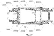
- a collision force transmission path F1/F2/F3 mainly includes an integrated hot-stamped engine compartment framework 1000; a collision force transmission path F4 is mainly formed by welding an integrated hot-stamped side wall outer panel reinforcing panel and a side wall inner panel; a collision force transmission path F5/F6 mainly includes an integrated hot-stamped rear floor framework 6000.
Landscapes
- Engineering & Computer Science (AREA)
- Chemical & Material Sciences (AREA)
- Combustion & Propulsion (AREA)
- Transportation (AREA)
- Mechanical Engineering (AREA)
- Manufacturing & Machinery (AREA)
- Body Structure For Vehicles (AREA)
Applications Claiming Priority (2)
| Application Number | Priority Date | Filing Date | Title |
|---|---|---|---|
| CN202310632981.0A CN116476926A (zh) | 2023-05-31 | 2023-05-31 | 一种车身结构及其制造方法和汽车 |
| PCT/CN2023/121343 WO2024244236A1 (zh) | 2023-05-31 | 2023-09-26 | 一种车身结构及其制造方法和汽车 |
Publications (2)
| Publication Number | Publication Date |
|---|---|
| EP4556352A1 true EP4556352A1 (de) | 2025-05-21 |
| EP4556352A4 EP4556352A4 (de) | 2025-12-10 |
Family
ID=87212105
Family Applications (1)
| Application Number | Title | Priority Date | Filing Date |
|---|---|---|---|
| EP23939210.3A Pending EP4556352A4 (de) | 2023-05-31 | 2023-09-26 | Fahrzeugkarosseriestruktur und herstellungsverfahren dafür sowie fahrzeug |
Country Status (3)
| Country | Link |
|---|---|
| EP (1) | EP4556352A4 (de) |
| CN (1) | CN116476926A (de) |
| WO (1) | WO2024244236A1 (de) |
Families Citing this family (3)
| Publication number | Priority date | Publication date | Assignee | Title |
|---|---|---|---|---|
| CN116476926A (zh) * | 2023-05-31 | 2023-07-25 | 深蓝汽车科技有限公司 | 一种车身结构及其制造方法和汽车 |
| CN117022453B (zh) * | 2023-07-28 | 2026-02-06 | 浙江吉利控股集团有限公司 | 一种车身后部总成及车辆 |
| CN116834836A (zh) * | 2023-08-02 | 2023-10-03 | 安徽江淮汽车集团股份有限公司 | 一种一体式高强度汽车后地板框架结构及总成 |
Family Cites Families (16)
| Publication number | Priority date | Publication date | Assignee | Title |
|---|---|---|---|---|
| JP3140505B2 (ja) * | 1991-09-11 | 2001-03-05 | マツダ株式会社 | 自動車の側部車体構造 |
| US20050189790A1 (en) * | 2004-02-27 | 2005-09-01 | Chernoff Adrian B. | Automotive side frame and upper structure and method of manufacture |
| KR101116634B1 (ko) * | 2009-07-27 | 2012-03-08 | 주식회사 성우하이텍 | 차량용 쇽업소버 하우징 제작방법 |
| DE102013002531B3 (de) * | 2013-02-13 | 2014-07-17 | Volkswagen Aktiengesellschaft | Karosseriestruktur für ein Fahrzeug |
| CN207889838U (zh) * | 2018-02-14 | 2018-09-21 | 东风小康汽车有限公司重庆分公司 | 减震降噪型汽车后轮罩 |
| EP3805075B1 (de) * | 2018-05-24 | 2022-09-14 | Nissan Motor Co., Ltd. | Seitenwandverkleidung |
| CA3102356A1 (en) * | 2018-06-25 | 2020-01-02 | Autotech Engineering S.L. | A body side structural frame of a vehicle |
| WO2022064256A1 (en) * | 2020-09-25 | 2022-03-31 | Arcelormittal | Side structure for a motor vehicle |
| WO2022096921A1 (en) * | 2020-11-06 | 2022-05-12 | Arcelormittal | Rear underfloor structure for a motor vehicle |
| CN113276954A (zh) * | 2021-06-15 | 2021-08-20 | 东风汽车集团股份有限公司 | 一种热成型激光拼焊一体式门环及加工方法 |
| DE102021206368A1 (de) * | 2021-06-22 | 2022-12-22 | Volkswagen Aktiengesellschaft | Verfahren zur Herstellung einer Stirnwand einer Kraftfahrzeugkarosserie und Verfahren zur Herstellung von Stirnwänden von Kraftfahrzeugkarosserien unterschiedlicher Kraftfahrzeugtypen |
| CN217415895U (zh) * | 2021-12-28 | 2022-09-13 | 东风汽车集团股份有限公司 | 一种车身前半部侧围总成及汽车 |
| CN114228418B (zh) * | 2022-01-28 | 2022-12-20 | 广东汇天航空航天科技有限公司 | 飞行汽车的车身结构及飞行汽车 |
| CN115402424B (zh) * | 2022-08-10 | 2023-06-06 | 岚图汽车科技有限公司 | 一种地板骨架总成、地板总成以及车辆 |
| CN115447672B (zh) * | 2022-10-25 | 2024-03-01 | 奇瑞汽车股份有限公司 | 一种汽车发动机舱结构及汽车 |
| CN116476926A (zh) * | 2023-05-31 | 2023-07-25 | 深蓝汽车科技有限公司 | 一种车身结构及其制造方法和汽车 |
-
2023
- 2023-05-31 CN CN202310632981.0A patent/CN116476926A/zh active Pending
- 2023-09-26 WO PCT/CN2023/121343 patent/WO2024244236A1/zh active Pending
- 2023-09-26 EP EP23939210.3A patent/EP4556352A4/de active Pending
Also Published As
| Publication number | Publication date |
|---|---|
| CN116476926A (zh) | 2023-07-25 |
| EP4556352A4 (de) | 2025-12-10 |
| WO2024244236A1 (zh) | 2024-12-05 |
Similar Documents
| Publication | Publication Date | Title |
|---|---|---|
| EP4556352A1 (de) | Fahrzeugkarosseriestruktur und herstellungsverfahren dafür sowie fahrzeug | |
| JP7240298B2 (ja) | 電動車両用バッテリーケースの製造方法および電動車両用バッテリーケース | |
| US9630656B2 (en) | Vehicle body structure | |
| CN216102401U (zh) | 车辆侧围加强结构和车辆 | |
| CN112660244B (zh) | 一种偏置碰防撞车体结构 | |
| CN112572608B (zh) | 车身结构和车辆 | |
| CN115489618A (zh) | 车身结构 | |
| CN115402424B (zh) | 一种地板骨架总成、地板总成以及车辆 | |
| CN116923561A (zh) | 车辆的车身组件以及车辆 | |
| CN116573054A (zh) | 一种侧围外板双门环加强结构及其制造方法和侧围外板加强总成 | |
| CN103625559B (zh) | 车辆的侧部车身结构 | |
| JP2011195110A (ja) | 車体側部構造 | |
| CN205554322U (zh) | 车身后纵梁、下车体及汽车 | |
| CN217396663U (zh) | 前围板总成及车辆 | |
| CN216102427U (zh) | 一种汽车门槛前部结构 | |
| CN115140192B (zh) | 车辆 | |
| CN116605299A (zh) | 一体式侧围内板双门环结构、成型工艺及车辆 | |
| CN117841625A (zh) | 车门和车辆 | |
| CN223494601U (zh) | 一种a柱总成及具有该a柱总成的车辆 | |
| CN208198604U (zh) | 一种汽车中央通道的支撑结构 | |
| CN119058832B (zh) | 车身结构与设有其的车辆 | |
| CN223408001U (zh) | 侧围加强结构及车辆 | |
| CN223812635U (zh) | 车身侧部结构及车辆 | |
| CN220009922U (zh) | 后地板总成及车辆 | |
| CN119796345B (zh) | 一种前纵梁连接结构 |
Legal Events
| Date | Code | Title | Description |
|---|---|---|---|
| STAA | Information on the status of an ep patent application or granted ep patent |
Free format text: STATUS: THE INTERNATIONAL PUBLICATION HAS BEEN MADE |
|
| PUAI | Public reference made under article 153(3) epc to a published international application that has entered the european phase |
Free format text: ORIGINAL CODE: 0009012 |
|
| STAA | Information on the status of an ep patent application or granted ep patent |
Free format text: STATUS: REQUEST FOR EXAMINATION WAS MADE |
|
| 17P | Request for examination filed |
Effective date: 20250214 |
|
| AK | Designated contracting states |
Kind code of ref document: A1 Designated state(s): AL AT BE BG CH CY CZ DE DK EE ES FI FR GB GR HR HU IE IS IT LI LT LU LV MC ME MK MT NL NO PL PT RO RS SE SI SK SM TR |
|
| A4 | Supplementary search report drawn up and despatched |
Effective date: 20251106 |
|
| RIC1 | Information provided on ipc code assigned before grant |
Ipc: B62D 23/00 20060101AFI20251031BHEP Ipc: B62D 25/00 20060101ALI20251031BHEP Ipc: B62D 25/02 20060101ALI20251031BHEP Ipc: B62D 25/08 20060101ALI20251031BHEP Ipc: B62D 25/16 20060101ALI20251031BHEP |