EP4549385A1 - Procédé de synthèse d'ammoniac à l'aide d'un dispositif de réaction et dispositif de réaction associé - Google Patents
Procédé de synthèse d'ammoniac à l'aide d'un dispositif de réaction et dispositif de réaction associé Download PDFInfo
- Publication number
- EP4549385A1 EP4549385A1 EP23207360.1A EP23207360A EP4549385A1 EP 4549385 A1 EP4549385 A1 EP 4549385A1 EP 23207360 A EP23207360 A EP 23207360A EP 4549385 A1 EP4549385 A1 EP 4549385A1
- Authority
- EP
- European Patent Office
- Prior art keywords
- heat exchange
- reactor
- exchange unit
- reaction
- heat
- Prior art date
- Legal status (The legal status is an assumption and is not a legal conclusion. Google has not performed a legal analysis and makes no representation as to the accuracy of the status listed.)
- Pending
Links
- QGZKDVFQNNGYKY-UHFFFAOYSA-N Ammonia Chemical compound N QGZKDVFQNNGYKY-UHFFFAOYSA-N 0.000 title claims abstract description 100
- 238000006243 chemical reaction Methods 0.000 title claims abstract description 93
- 229910021529 ammonia Inorganic materials 0.000 title claims abstract description 50
- 238000000034 method Methods 0.000 title claims abstract description 38
- 230000015572 biosynthetic process Effects 0.000 title claims abstract description 22
- 238000003786 synthesis reaction Methods 0.000 title claims abstract description 22
- 239000007789 gas Substances 0.000 claims abstract description 70
- 230000008569 process Effects 0.000 claims abstract description 28
- IJGRMHOSHXDMSA-UHFFFAOYSA-N Atomic nitrogen Chemical compound N#N IJGRMHOSHXDMSA-UHFFFAOYSA-N 0.000 claims abstract description 25
- 239000001257 hydrogen Substances 0.000 claims abstract description 19
- 229910052739 hydrogen Inorganic materials 0.000 claims abstract description 19
- UFHFLCQGNIYNRP-UHFFFAOYSA-N Hydrogen Chemical compound [H][H] UFHFLCQGNIYNRP-UHFFFAOYSA-N 0.000 claims abstract description 15
- 229910052757 nitrogen Inorganic materials 0.000 claims abstract description 12
- 239000003054 catalyst Substances 0.000 claims abstract description 9
- 239000000376 reactant Substances 0.000 claims abstract description 9
- 238000009833 condensation Methods 0.000 claims description 64
- 230000005494 condensation Effects 0.000 claims description 64
- 239000000463 material Substances 0.000 claims description 12
- 238000001816 cooling Methods 0.000 claims description 10
- 238000011084 recovery Methods 0.000 claims description 10
- 239000007787 solid Substances 0.000 claims description 9
- 230000007774 longterm Effects 0.000 claims description 4
- 239000007788 liquid Substances 0.000 claims description 3
- 239000000047 product Substances 0.000 description 17
- 230000008901 benefit Effects 0.000 description 16
- 238000004519 manufacturing process Methods 0.000 description 14
- 239000000126 substance Substances 0.000 description 11
- 239000000654 additive Substances 0.000 description 9
- 230000000996 additive effect Effects 0.000 description 9
- UFWIBTONFRDIAS-UHFFFAOYSA-N Naphthalene Chemical compound C1=CC=CC2=CC=CC=C21 UFWIBTONFRDIAS-UHFFFAOYSA-N 0.000 description 8
- 229910045601 alloy Inorganic materials 0.000 description 6
- 239000000956 alloy Substances 0.000 description 6
- 239000002826 coolant Substances 0.000 description 6
- 239000000498 cooling water Substances 0.000 description 5
- 238000010586 diagram Methods 0.000 description 5
- 239000012530 fluid Substances 0.000 description 5
- 239000003337 fertilizer Substances 0.000 description 4
- 150000002431 hydrogen Chemical class 0.000 description 4
- 239000007858 starting material Substances 0.000 description 4
- 238000011161 development Methods 0.000 description 3
- 230000018109 developmental process Effects 0.000 description 3
- 230000005611 electricity Effects 0.000 description 3
- 239000002608 ionic liquid Substances 0.000 description 3
- 230000007704 transition Effects 0.000 description 3
- 239000003570 air Substances 0.000 description 2
- 239000006227 byproduct Substances 0.000 description 2
- 230000006835 compression Effects 0.000 description 2
- 238000007906 compression Methods 0.000 description 2
- 238000005868 electrolysis reaction Methods 0.000 description 2
- 230000002349 favourable effect Effects 0.000 description 2
- 239000002803 fossil fuel Substances 0.000 description 2
- 229910001026 inconel Inorganic materials 0.000 description 2
- 230000010354 integration Effects 0.000 description 2
- 239000007769 metal material Substances 0.000 description 2
- 238000005191 phase separation Methods 0.000 description 2
- 239000011148 porous material Substances 0.000 description 2
- 238000000926 separation method Methods 0.000 description 2
- 238000003860 storage Methods 0.000 description 2
- 229910000601 superalloy Inorganic materials 0.000 description 2
- QGZKDVFQNNGYKY-UHFFFAOYSA-O Ammonium Chemical compound [NH4+] QGZKDVFQNNGYKY-UHFFFAOYSA-O 0.000 description 1
- UGFAIRIUMAVXCW-UHFFFAOYSA-N Carbon monoxide Chemical compound [O+]#[C-] UGFAIRIUMAVXCW-UHFFFAOYSA-N 0.000 description 1
- 238000009620 Haber process Methods 0.000 description 1
- 229920000877 Melamine resin Polymers 0.000 description 1
- 229910002651 NO3 Inorganic materials 0.000 description 1
- NHNBFGGVMKEFGY-UHFFFAOYSA-N Nitrate Chemical compound [O-][N+]([O-])=O NHNBFGGVMKEFGY-UHFFFAOYSA-N 0.000 description 1
- 239000004952 Polyamide Substances 0.000 description 1
- XSQUKJJJFZCRTK-UHFFFAOYSA-N Urea Chemical compound NC(N)=O XSQUKJJJFZCRTK-UHFFFAOYSA-N 0.000 description 1
- 239000012080 ambient air Substances 0.000 description 1
- QVGXLLKOCUKJST-UHFFFAOYSA-N atomic oxygen Chemical compound [O] QVGXLLKOCUKJST-UHFFFAOYSA-N 0.000 description 1
- 239000004202 carbamide Substances 0.000 description 1
- 230000008859 change Effects 0.000 description 1
- 239000007795 chemical reaction product Substances 0.000 description 1
- 239000003638 chemical reducing agent Substances 0.000 description 1
- 239000000110 cooling liquid Substances 0.000 description 1
- 230000007797 corrosion Effects 0.000 description 1
- 238000005260 corrosion Methods 0.000 description 1
- 238000006073 displacement reaction Methods 0.000 description 1
- 238000005265 energy consumption Methods 0.000 description 1
- 238000004146 energy storage Methods 0.000 description 1
- 238000005516 engineering process Methods 0.000 description 1
- 239000002360 explosive Substances 0.000 description 1
- 239000000835 fiber Substances 0.000 description 1
- 239000003546 flue gas Substances 0.000 description 1
- 239000000446 fuel Substances 0.000 description 1
- 230000004927 fusion Effects 0.000 description 1
- 239000005431 greenhouse gas Substances 0.000 description 1
- 238000010438 heat treatment Methods 0.000 description 1
- 230000003993 interaction Effects 0.000 description 1
- 230000002503 metabolic effect Effects 0.000 description 1
- 229910001092 metal group alloy Inorganic materials 0.000 description 1
- 238000005457 optimization Methods 0.000 description 1
- 239000001301 oxygen Substances 0.000 description 1
- 229910052760 oxygen Inorganic materials 0.000 description 1
- 239000004033 plastic Substances 0.000 description 1
- 229920003023 plastic Polymers 0.000 description 1
- 229920002647 polyamide Polymers 0.000 description 1
- 239000000843 powder Substances 0.000 description 1
- 230000001737 promoting effect Effects 0.000 description 1
- 230000009467 reduction Effects 0.000 description 1
- 150000003839 salts Chemical class 0.000 description 1
- 239000004753 textile Substances 0.000 description 1
- 229920001187 thermosetting polymer Polymers 0.000 description 1
- 238000011144 upstream manufacturing Methods 0.000 description 1
- 239000002918 waste heat Substances 0.000 description 1
- XLYOFNOQVPJJNP-UHFFFAOYSA-N water Substances O XLYOFNOQVPJJNP-UHFFFAOYSA-N 0.000 description 1
Images


Classifications
-
- C—CHEMISTRY; METALLURGY
- C01—INORGANIC CHEMISTRY
- C01C—AMMONIA; CYANOGEN; COMPOUNDS THEREOF
- C01C1/00—Ammonia; Compounds thereof
- C01C1/02—Preparation, purification or separation of ammonia
- C01C1/04—Preparation of ammonia by synthesis in the gas phase
- C01C1/0405—Preparation of ammonia by synthesis in the gas phase from N2 and H2 in presence of a catalyst
- C01C1/0447—Apparatus other than synthesis reactors
- C01C1/0452—Heat exchangers
-
- C—CHEMISTRY; METALLURGY
- C01—INORGANIC CHEMISTRY
- C01C—AMMONIA; CYANOGEN; COMPOUNDS THEREOF
- C01C1/00—Ammonia; Compounds thereof
- C01C1/02—Preparation, purification or separation of ammonia
- C01C1/04—Preparation of ammonia by synthesis in the gas phase
- C01C1/0405—Preparation of ammonia by synthesis in the gas phase from N2 and H2 in presence of a catalyst
- C01C1/0458—Separation of NH3
- C01C1/047—Separation of NH3 by condensation
Definitions
- the invention relates to a process for ammonia synthesis by means of a reaction device according to claim 1. Furthermore, the invention relates to a corresponding reaction device according to claim 6.
- Ammonia which has the chemical formula NH 3 , is a particularly important basic chemical and, for example, was produced on the order of 140 million tons in 2020.
- Ammonia is formed in an equilibrium reaction between the elements hydrogen and nitrogen according to the equation:
- the required nitrogen is extracted from the ambient air, with the oxygen contained in the air being separated, for example, and the nitrogen being purified using air separation processes.
- Hydrogen the energy-rich starting material for ammonia synthesis, has been supplied almost exclusively by fossil fuels for a hundred years.
- Derivative products using ammonia as a starting material include urea, ammonium, and nitrate fertilizers, with over 80% of global ammonia production being used for fertilizers.
- chemical products such as polyamides for textile fibers, plastics and materials, thermoset melamine resins, explosives, reducing agents in flue gas denitrification, and and so on, based on ammonia.
- NH 3 is also being discussed as a hydrogen storage substance and as an energy carrier.
- Ammonia synthesis currently consumes almost 2% of all fossil fuels. Ammonia production also generates approximately 500 million tons of CO2 , which corresponds to approximately 2% of anthropogenic CO2 emissions from energy sources—a remarkable amount for a single product molecule.
- the object of the present invention is to provide a process and a reaction device for ammonia synthesis which is particularly well scalable, especially with regard to small plants, and is also particularly efficient.
- a first aspect of the invention relates to a process for ammonia synthesis by means of a reaction device.
- gaseous fluid or feed gas which comprises at least N 2 and H 2 or nitrogen and hydrogen as reactants, is passed through an inlet opening into a reactor device of the reaction apparatus under pressure over a catalyst, wherein ammonia is formed as a product and this is passed in gaseous form, in particular with other products, as a wet gas, to a condensation device which has at least three heat exchange units formed monolithically with one another or in particular one after the other along a condensation direction, in order to flow through them, wherein the ammonia NH 3 as a product from the introduced, in particular wet gas, is condensed as condensate.
- the first heat exchange unit is operated as a countercurrent cooler or feed-effluent exchanger, whereby the feed gas with dry gas or residual gas from which ammonia has already condensed, and the second heat exchange unit, which in particular borders seamlessly on the first heat exchange unit or functionally extends it, is operated as a condenser, whereby the gaseous reactants are separated from the liquid pressurized condensate or product, and the third heat exchange unit is operated as an aftercooler and thereby the pressurized condensate is subcooled, which, in particular at room temperature, is discharged via a collecting duct and furthermore the dry gas or residual gas is discharged from the reaction device via an outlet opening.
- the monolithic condensation device can be designed, manufactured, or produced, in particular, using additive manufacturing.
- heat exchangers and a phase separator which is formed by the second and third heat exchange units, in particular in the transition region of the latter, are formed from a block, in particular by additive manufacturing and/or comprising at least a partially metallic material.
- Ammonia synthesis using the process according to the invention is an equilibrium reaction, with the chemical equilibrium shifting into an attractive range, particularly at high pressure. For example, a high reaction rate can be achieved even at 400 °C, while at the same time an acceptable equilibrium position can be achieved at 500 bar (50 MPa) pressure, allowing the use of a particularly small amount of catalyst.
- Conversion rates of, for example, 60% can be achieved, which, due to the chemical equilibrium, allows for a much higher reaction rate and product yield compared to conventional processes, which typically take place at 200 bar and 330 °C.
- One advantage of the process is its particularly high efficiency in ammonia synthesis.
- the reactor device has a reaction chamber which is in particular monolithic and formed with the condensation device and which is formed by a preheating unit and a second reactor surrounded by a heat pipe heat exchange reservoir and by a first reactor surrounded by a heat pipe heat recovery reservoir which is operated, for example, with naphthalene up to approx. 430 °C, through which the gaseous fluid or feed gas is preheated and reacted.
- a first reaction zone is provided which is advantageously formed by tubes in a heat bath.
- high-temperature heat can be released into a useful heat system which is used to preheat the wet gas or feed gas.
- This has the advantage that this is particularly exergetically favorable; for example, the low temperature level of, for example, 350 °C can be used initially to further heat up using reaction heat and, for example, to extract it via the heat pipes at higher temperatures than the useful heat.
- the reaction chamber is formed by a pressure vessel or enclosed by a pressure vessel and thus delimited by it, so that the gaseous fluid or feed gas is or can be introduced into the reaction chamber at at least 300 and in particular 400 bar and particularly preferably 500 bar.
- the reaction device is designed such that the reaction or condensation takes place under a particularly high Pressures above 300 bar, and preferably 500 bar, can be carried out. This has the advantage of enabling a particularly high reaction yield.
- the pressure of the feed gas is generated by means of an ionic compressor or a compressor with ionic liquid.
- an isothermal displacement processor which can dissipate the heat generated during compression by an ionic liquid, is used to compress the dry gas or feed gas.
- reaction runs can be carried out or take place in a cascade one after the other, wherein for this purpose, in particular a corresponding number of reaction devices, in particular monolithically manufactured, are connected in series.
- the respective reactor device of the respective reaction device advantageously comprises a respective heat exchange reservoir with a preheating unit and a second reactor or is designed together with these.
- the reaction device can have several reactor devices and condensation devices which are connected in series in a fluidically conductive manner, so that dry gas flowing out of a condensation device arranged first in the flow direction of the fluid flows into the next reactor device as a quasi feed gas or feed gas.
- an intermediate condensation can enable a particularly high yield because ammonia can be removed from the equilibrium in each case.
- the cascade allows the product or ammonia to condense out in each run, wherein in particular only indispensable heat losses, in particular
- An axial heat pipe (in the respective condensation device) allows the heat released during condensation to flow into the cooling water.
- the heat in the particularly hot feed gas product stream is used to heat the residual gas coming from the condenser.
- Useful heat can be extracted from the heat recovery reservoir of the first reactor at 400 °C. This has the advantage of allowing a particularly high ammonia yield to be achieved.
- a second aspect of the invention relates to a reaction device for a process according to the first aspect of the invention.
- the reaction device according to the invention comprises a reactor device, which in particular has a preheating unit, a first reactor and a second reactor, and a condenser device, which has at least three heat exchange units formed monolithically with one another or one after the other, which in particular functionally merge into one another, wherein of the heat exchange units, the first heat exchange unit is designed as a counterflow cooler or feed-effluent exchanger, the second heat exchange unit as a condenser and the third heat exchange unit as an aftercooler, wherein in particular the second and partly the third heat exchange unit together form a phase separator which serves to separate the condensate of the ammonia from the gas.
- the first heat exchange unit which is designed in particular as a counterflow cooler, is formed by a plurality of solid plates arranged parallel to one another and spaced apart, wherein two adjacent plates each have a plate channel, in particular oriented along a condensation direction form.
- adjacent plate channels are in particular open to one another.
- the second heat exchange unit is formed by porous demister plates, which each seamlessly continue the plates of the first heat exchange unit or merge into them, but can, for example, change a circumference or the like.
- the third heat exchange unit which is in particular designed as a condensate cooler, is formed from alternating solid plates and porous collecting plates that lie next to one another, which are arranged essentially perpendicular to the plates of the first and second heat exchange units and have at least one cooling channel or at least two cooling channels for the flow of, in particular, cold coolant, and a collecting channel for the condensate in an end region lying in a condensation direction.
- the condensation device is formed from functionally interconnected or interleaved heat exchange units, so that in particular the porous region of the second and third heat exchange units, which merge seamlessly into one another, forms the condenser or phase separator.
- a temperature gradient can be formed via the cooling channels up to the first heat exchange unit.
- the alternately opened plates result in the possibility of countercurrent cooling or a feed-effluent cooler, so that in particular at the end opposite the second and third heat exchange units, the feed gas flows into one of the plate channels and through a porous demister plate in the heat exchange unit into the next adjacent plate channel, where the dry gas can flow out again via the plate channel to the upper end of the first heat exchange unit.
- the reaction device has a plurality of reactor devices and condensation devices, in particular monolithically formed with one another.
- the respective condensation device or a plurality of combined or flanged-together condensation devices and/or reactor devices is formed as a single piece and/or additively manufactured.
- the respective condensation device can be formed as a single piece, i.e. in particular seamlessly from a single workpiece, and this can be formed in particular by means of additive manufacturing. This results in the advantage that, for example, a particularly cost-effective provision of the reaction device is enabled.
- the functionality of, for example, the condensation device can be provided in a particularly reliable manner.
- a material of the (respective) reactor device and condensation device is long-term stable against high pressure and/or high temperature and/or ammonia and/or hydrogen and/or nitrogen.
- the material which is, for example, in particular a metallic alloy, is selected such that the condensation device and thus the reaction device for ammonia synthesis can be designed to be as durable as possible. This results in the advantage that, for example, wear is particularly low, whereby the reaction device or the process can be designed particularly cost-effectively.
- the material comprises the alloy with the EN number 2.4856, DIN NiCr22Mo9Nb, also referred to as Inconel ® 625 or IN625, and/or with the EN number 2.4668, DIN NiCr19Fe19Nb5Mo3, also referred to as INCONEL ® 718 or IN718, and/or the material has a thermal conductivity of less than 15 and in particular 11 W/(m*K), whereby a temperature gradient can be built up or formed in the respective condensation device along the condensation direction (or axially).
- an error message and/or a request to enter user feedback is issued and/or a default setting and/or a predetermined initial state is set.
- FIG 1 shows a schematic flow diagram for a process for ammonia synthesis by means of a reaction device 10, which comprises a reactor device 12 and condensation devices 16.
- feed gas 14 which comprises at least nitrogen and hydrogen as reactants, is passed through an inlet opening under pressure into a reaction chamber 32 of the reactor devices 12 over or onto a catalyst 66, whereby ammonia is formed as a product in chemical equilibrium.
- the ammonia in particular in gaseous form, forms a wet gas 19 together with the residues of the feed gas 14 or with any other by-products formed therefrom. However, no by-products are generally formed.
- wet gas describes that it contains at least one product that is to be condensed out.
- the wet gas from the reactor device is fed into a condensation device 16, which has at least three monolithic heat exchange units formed one after the other or one after the other, and in which the ammonia as a product of the introduced gas is condensed as condensate 20.
- the first heat exchange unit 24 is operated as a countercurrent cooler, whereby the wet gas 19 exchanges heat with dry gas 22 or residual gas from which ammonia has already condensed.
- the second heat exchange unit 26 is operated as a condenser, whereby the gaseous reactants or the gaseous fluid are separated from the liquid pressurized condensate 20.
- the third heat exchange unit 28 is operated as an aftercooler and thereby subcools or further cools the pressurized condensate 20, in particular to room temperature.
- This subcooled condensate 20 is discharged via a collecting channel 30, and the dry gas 22 is discharged via an outlet opening.
- the condensation device 16 in particular monolithically with the reactor device 12 (see FIG 4 ) is formed, which comprises a preheating unit 36, which is formed in particular by a first reactor 34 surrounded by a heat pipe temperature control unit. This allows the feed gas 14 to be preheated.
- the reaction chamber 32 contains the preheating unit 36 and a second reactor 35 surrounded by a heat exchange reservoir 38, which is advantageously designed as a heat pipe heat exchange reservoir, and the first reactor 34 surrounded by a heat recovery reservoir 40, which is advantageously designed as a heat pipe heat recovery reservoir.
- the feed gas 14 is preheated and reacted.
- the reaction chamber 32 is delimited by or formed by a pressure vessel, so that the feed gas 14 can be introduced into the reaction chamber 32 at a particularly high pressure, at least 400 and in particular 500 bar.
- the feed gas 14, before reaching the preheating unit 36 must have a temperature of 50°C, with the hydrogen content being 75% and the nitrogen content being 25%.
- an ionic compressor can advantageously be provided, which thus provides 500 bar compression technology, particularly for small systems, such as the reaction device 10.
- the temperature of the feed gas 14 is heated to 400°C or at least 350°C by means of a cooling medium, such as cooling water or naphthalene, which is cyclically evaporated and condensed in the heat pipe temperature control unit.
- a cooling medium such as cooling water or naphthalene
- the wet gas 19 also has a temperature of at least 350°C.
- the wet gas 19 is then fed into the condensation device 16.
- the first heat exchange unit 24 there is operated as a counterflow cooler, so that the wet gas 19 flows through a first plate channel 44 to the second heat exchange unit 26 for phase separation and then flows back as dry gas 14 in an adjacent plate channel 44 to the end of the first heat exchange unit 24 facing away from the second heat exchange unit 26.
- the dry gas 22 leaves the condensation device 16 at a temperature of 350 °C, for example, by being discharged via a vent opening or, in an advantageous embodiment, is fed directly into a further reaction device 10 or reactor device 12, for example in order to carry out several cascading reactor runs or To enable consecutive reaction runs. This is described in FIG 6 taken a closer look.
- the second heat exchange unit 26 serves as a condenser in which the condensate 20 is separated from the gas, this taking place at a temperature of, for example, 30 °C and the second heat exchange unit 26 can thus be used or is used as a cooler and phase separator 64.
- a heat sink 18, the heat exchange reservoir 38, and the heat recovery reservoir 40 symbolize the operating temperature specified by the respective cooling medium or cooling liquid.
- the heat exchange unit 28 is cooled by means of a further cooling medium, enabling particularly advantageous subcooling of the condensate 20 to, for example, 14 °C or room temperature.
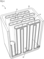
- FIG 2 shows a schematic perspective view of a condensation device 16 for a reaction device 10 presented here for carrying out the process presented here.
- FIG 2 the condensation device 16 without a housing or wall, which in particular forms a further pressure vessel.
- the condensation device 16 comprises at least three heat exchange units 24, 26, 28 formed together, of which the first heat exchange unit 24 is designed as a counterflow cooler, the second heat exchange unit 26 as a condenser, and the third heat exchange unit 28 as an aftercooler.
- the first heat exchange unit 24 is formed by a plurality of solid plates 42 arranged parallel to one another and spaced apart, wherein two adjacent plates 42 each form a plate channel 44, which is each axially oriented essentially along a condensation direction 54 and the plate channels 44 are alternately open, so that via the respective plate channel 44, which extends into the second heat exchange unit 26 extends, since the second heat exchange unit 26 is designed such that the respective first plates 42 are seamlessly continued by porous demister plates 46, phase separation is possible in the second heat exchange unit, and the alternating opening of the plate channels 44 thus allows the first heat exchange unit 24 to be operated as a counterflow cooler.
- the third heat exchange unit 28 is formed from alternating solid plates 48 and porous collecting plates 50, which are arranged essentially perpendicular to the plates 42 and 46 of the first and second heat exchange units 24 and 26.
- the third heat exchange unit 28 comprises at least one cooling channel 52 and the collecting channel 30 for the condensate 20, which is located in an end region 56, in particular in the condensation direction 54.
- FIG 3 shows a schematic sectional view of a section of the condensation device 16, showing the transition from the solid plates 42 to the porous demistor plates 46, so that adjacent plate channels 44 serve for the inflow of the feed gas 14 and the outflow of the dry gas 22.
- the condensate 20 is discharged via the collecting channel 30, while it is further cooled by the third heat exchange unit 28.
- the porous material of the porous demistor plates 46 merges into the porous material of the porous collecting plates 50, which are each surrounded by the intervening solid cooling plates - the plates 48 - for particularly advantageous cooling.
- a material of the condensation device 16 is particularly stable in the long term against high pressure and/or high temperatures and/or ammonia and/or hydrogen and/or nitrogen, so that the reaction device 10 can be designed to be particularly durable.
- the material comprises, for example, the alloy IN625 and/or IN718, the former having a thermal conductivity of, for example, 10 W/(m*K), whereby a temperature gradient, in particular along the condensation direction 54, so that a temperature gradient can be formed, in particular due to the thin wall thickness of the plates 42 and 46 and thus axially or in the condensation direction 54.
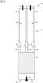
- FIG 4 shows a schematic perspective view of a preheating unit 36, which is formed by a first reactor 34 surrounded by a heat pipe temperature control unit.
- the reactants or the feed gas 14 are conveyed through tubes of the first reactor 34 towards or to the condensation device 16 and are preheated by a cooling medium, which is represented, for example, by the heat exchange reservoir 38 or heat recovery reservoir 40.
- a cooling medium which is represented, for example, by the heat exchange reservoir 38 or heat recovery reservoir 40.
- Naphthalene for example, can be used as the cooling medium in the heat pipe temperature control unit. This is passed through the heat pipes of the heat pipe temperature control unit at, for example, 400°C and accordingly heats the feed gas introduced, for example, at 50°C, to 350°C to 400°C for the condensation device 16.
- FIG 5 shows a schematic flow diagram for the process in which the starting materials are provided and fed to the reaction device 10. Hydrogen H 2 is obtained via an electrolyzer 58, which is supplied with electricity 60, wherein the electrolyzer 58 is advantageously coupled to the heat recovery reservoir 40 or at least has the same temperature.
- Both nitrogen and hydrogen are conveyed to the reaction device 10 by means of compressors 62.
- FIG 6 shows several jointly formed reaction devices 10, each with a condensation device 16 and a reactor device 12, which are connected in series so that several reactor runs or runs of the process can be carried out in a cascade one after the other.
- FIG 6 is indicated by "[...]” that virtually any number of further reaction devices 10 can be arranged between the first and the last reaction device 10. For example, five reaction devices 10 can be connected in series, and condensate 20 can be discharged from each of them, with the dry gas 22 discharged from the upstream condensation device 16 serving as feed gas 14 for the next reactor device 12.
- the reaction device 10 thus provides a highly integrated reactor, which can be manufactured, for example, by additive manufacturing, in particular by powder bed fusion. Additive manufacturing results in particularly high structural strength and a favorable geometry for thermal conductivity and heat integration, particularly for the condensation device 16.
- the reaction device 10 enables an advantageous bundling of complexity for the ammonia synthesis, in particular by cascading several reactor devices 12 and condensation devices 16, as well as by the possibility of a common heat exchange, for example via the heat sink 18, the heat exchange reservoir 38 and the heat recovery reservoir 40, whereby a product condensation of the condensate 20 is particularly advantageously enabled, in particular in several stages.
- the two reaction zones or reactors 34 and 35 make it possible to achieve high conversions (higher temperature, faster conversion) while still promoting chemical equilibrium (lower temperature, residual conversion until equilibrium).
- High-temperature heat is transferred to the useful heat system via the heat pipes of the heat pipe temperature control unit, which is used to preheat the feed gas or feed gas 14. From an exergetic perspective, it may be advantageous to initially utilize the lower temperature level of, for example, 350 °C of the second reaction zone and further heat it with reaction heat, and then extract it from the first reaction zone at a higher temperature as useful heat.
- a heat exchanger is enabled, in particular, via the first heat exchange unit 24 to prevent heat loss. Condensation in the second heat exchange unit 26 and subcooling of the pressurized condensate 20 in the third heat exchange unit 28 to room temperature are enabled.
- the IN625 alloy conducts heat particularly poorly for a metallic material.
- Long components with thin walls in the direction of the temperature gradient therefore lose very little heat axially and are capable of establishing a temperature gradient.
- Thin plates, such as plates 42 and 46, still exchange sufficient heat radially despite their poor thermal conductivity.
- a compressor with ionic liquid which can, for example, also produce small quantities of 18 kg of hydrogen per hour at a pressure of 500 bar, for example in compact 10 t container units.
- At least one of the compressors 62 can be designed as an ionic compressor.
- the reactor system or the first reactor 34 in the heat bath of the heat pipe cooler can, for example, be operated particularly efficiently due to additive manufacturing, since, for example, functional elements can be manufactured simultaneously without additional effort.
- the ammonia product or the condensate 20 can each be condensed in the respective condensation device 16, whereby only the essential heat loss via axial heat conduction or along the condensation direction 54 in the respective condensation device 16 and the heat released during condensation and subcooling flow into the cooling water.
- the heat in the hot product stream i.e. from the respective feed gas 14, is used to heat the residual gas coming from the condenser. Useful heat is extracted, in particular, at 400 °C.
- the process and reaction device 10 presented here offer several advantages. Compared to conventional ammonia synthesis, the process presented here offers several benefits that are particularly relevant in the context of decentralized renewable energies.
- the chemical equilibrium can shift into an attractive range when operating at very high pressure.
- conversions of, for example, 60% can be achieved even at 400 °C, with a high reaction rate and the use of little catalyst.
- Temperatures between 200 °C and 330 °C are common in large-scale industrial plants, with a much lower reaction rate.
- the isothermal nature of the reaction device 10 ensures controllability and precisely predictable behavior (without hot spots/cold spots).
- the isothermal nature of the reactor also enables precise operation of the catalyst without damage.
- the reaction device 10 can be constructed particularly compactly, enabling heating and cooling with particularly low energy consumption, and keeping it warm even when not in operation with only minimal thermal loss.
- the reaction device 10 is monolithic, particularly manufactured from a high-performance alloy, and is therefore a material system that is very resistant and tough even at high temperatures and, moreover, very corrosion-resistant, yet small structures can still be precisely formed.
- the isothermal nature of the process and thus in the reaction device 10 can be achieved using molten salt or a heat pipe temperature control unit, for example, with naphthalene as the working medium, which can be operated up to approximately 450°C.
- Heat efficiency so that only small amounts of heat are released into cold cooling water, where they are lost for use. Heat is released in the system or reaction device 10 according to exergetic considerations only at the required temperature level. High-temperature heat is extracted and can be used. This allows for yields of more than 95% without a cycle gas compressor, with only the cold gas being compressed. Exergetic efficiency, for example, results in a robust eco-design.
- the process is also easy to implement and operate the reaction device 10, since, for example, few connecting lines are required, no seals are required and therefore no leakage risks are eliminated at the transition between individual heat exchange units 24, 26, 28 and the preheating unit 36.
- additive manufacturing can also be used to machine a high-performance alloy such as IN625 with the required fragility, thus enabling a particularly compact design and, compared to conventional systems where reactors can have a diameter of 4 m, for example, a high pressure of 500 bar at 500 °C can be achieved.
- the condensation device 16 allows for the realization of a multifunctional monomaterial (multifunctional monomaterial), making the reaction device 10 particularly easy to recycle.
- a closed metabolic cycle for reactor body dismantling which is particularly desirable for high-quality alloys, can be easily enabled.
- an ionic compressor is particularly efficient, and decentralized heat utilization is possible.
- Renewable energy generated in a decentralized manner over a large area can be used particularly advantageously by the method and reaction device 10 presented, so that, for example, a decentralized production of fertilizers without CO2 release is made possible.
Landscapes
- Chemical & Material Sciences (AREA)
- Organic Chemistry (AREA)
- Chemical Kinetics & Catalysis (AREA)
- Analytical Chemistry (AREA)
- Inorganic Chemistry (AREA)
- Physical Or Chemical Processes And Apparatus (AREA)
- Devices And Processes Conducted In The Presence Of Fluids And Solid Particles (AREA)
Priority Applications (3)
| Application Number | Priority Date | Filing Date | Title |
|---|---|---|---|
| EP23207360.1A EP4549385A1 (fr) | 2023-11-02 | 2023-11-02 | Procédé de synthèse d'ammoniac à l'aide d'un dispositif de réaction et dispositif de réaction associé |
| US18/934,449 US20250145481A1 (en) | 2023-11-02 | 2024-11-01 | Ammonia Synthesis Using A Reaction Apparatus |
| AU2024259712A AU2024259712A1 (en) | 2023-11-02 | 2024-11-04 | Process for ammonia synthesis using a reaction apparatus and associated reaction apparatus |
Applications Claiming Priority (1)
| Application Number | Priority Date | Filing Date | Title |
|---|---|---|---|
| EP23207360.1A EP4549385A1 (fr) | 2023-11-02 | 2023-11-02 | Procédé de synthèse d'ammoniac à l'aide d'un dispositif de réaction et dispositif de réaction associé |
Publications (1)
| Publication Number | Publication Date |
|---|---|
| EP4549385A1 true EP4549385A1 (fr) | 2025-05-07 |
Family
ID=88690252
Family Applications (1)
| Application Number | Title | Priority Date | Filing Date |
|---|---|---|---|
| EP23207360.1A Pending EP4549385A1 (fr) | 2023-11-02 | 2023-11-02 | Procédé de synthèse d'ammoniac à l'aide d'un dispositif de réaction et dispositif de réaction associé |
Country Status (3)
| Country | Link |
|---|---|
| US (1) | US20250145481A1 (fr) |
| EP (1) | EP4549385A1 (fr) |
| AU (1) | AU2024259712A1 (fr) |
Citations (4)
| Publication number | Priority date | Publication date | Assignee | Title |
|---|---|---|---|---|
| US4311671A (en) * | 1979-09-14 | 1982-01-19 | Imperial Chemical Industries Limited | Synthesis reactor |
| US4689208A (en) * | 1984-04-25 | 1987-08-25 | Imperial Chemical Industries Plc | Ammonia synthesis |
| WO2006018610A1 (fr) * | 2004-08-20 | 2006-02-23 | Davy Process Technology Ltd | Processus destine a une utilisation dans des reactions en phase gazeuse |
| US20210308645A1 (en) * | 2018-07-27 | 2021-10-07 | Siemens Aktiengesellschaft | Reactor for Carrying Out a Chemical Balanced Reaction |
-
2023
- 2023-11-02 EP EP23207360.1A patent/EP4549385A1/fr active Pending
-
2024
- 2024-11-01 US US18/934,449 patent/US20250145481A1/en active Pending
- 2024-11-04 AU AU2024259712A patent/AU2024259712A1/en active Pending
Patent Citations (4)
| Publication number | Priority date | Publication date | Assignee | Title |
|---|---|---|---|---|
| US4311671A (en) * | 1979-09-14 | 1982-01-19 | Imperial Chemical Industries Limited | Synthesis reactor |
| US4689208A (en) * | 1984-04-25 | 1987-08-25 | Imperial Chemical Industries Plc | Ammonia synthesis |
| WO2006018610A1 (fr) * | 2004-08-20 | 2006-02-23 | Davy Process Technology Ltd | Processus destine a une utilisation dans des reactions en phase gazeuse |
| US20210308645A1 (en) * | 2018-07-27 | 2021-10-07 | Siemens Aktiengesellschaft | Reactor for Carrying Out a Chemical Balanced Reaction |
Also Published As
| Publication number | Publication date |
|---|---|
| US20250145481A1 (en) | 2025-05-08 |
| AU2024259712A1 (en) | 2025-05-22 |
Similar Documents
| Publication | Publication Date | Title |
|---|---|---|
| DE2549439C2 (fr) | ||
| EP3678767B1 (fr) | Réacteur de conversion et mise en oeuvre du procédé associé | |
| EP3497058B1 (fr) | Dispositif de synthèse et procédé de production d'un produit | |
| DE2710247A1 (de) | Verfahren zur ammoniaksynthese und konverter hierfuer | |
| EP3585509B1 (fr) | Échangeur de chaleur et réacteur | |
| EP2215013B1 (fr) | Procédé amélioré de production d'acide prussique par déshydratation catalytique de formamide gazeux | |
| EP3072855A1 (fr) | Procédé et système de traitement d'une boue contenant des composants organiques | |
| DE60036569T2 (de) | Verfahren und apparatur wobei eine plattenvorrichtung zum beheizen und vorheizen verwendet wird | |
| DE3420579A1 (de) | Hochleistungs-methanierungsvorrichtung | |
| DE1812734A1 (de) | Verfahren und Vorrichtung zur Dehydrierung von alkylierten aromatischen Verbindungen | |
| EP4496913B1 (fr) | Système de co-électrolyse à haute température, installation de co-électrolyse à haute température et procédé de production de gaz de synthèse | |
| EP4549385A1 (fr) | Procédé de synthèse d'ammoniac à l'aide d'un dispositif de réaction et dispositif de réaction associé | |
| DE102016107124A1 (de) | NH3 Synthesekonfiguration für Großanlagen | |
| EP3341113B1 (fr) | Réacteur et procédé de conversion catalytique d'un mélange de gaz | |
| WO2017067648A1 (fr) | Procédé de production de gaz de synthèse | |
| EP1670746B1 (fr) | Procede pour reguler la temperature d'entree de reacteur dans le cadre de la preparation de methylamines | |
| EP4327929B1 (fr) | Réacteur à plaques pour la synthèse du méthanol | |
| DE19852894B4 (de) | Verfahren zur Gewinnung von Phthalsäureanhydrid durch katalytische Gasphasenreaktion und Vorrichtung zur Durchführung des Verfahrens | |
| EP3365393B1 (fr) | Système d'échangeur de chaleur pour installation de production de noir de carbone industriell | |
| EP3135370B1 (fr) | Reacteur destine a produire du gaz de synthese par reformage a la vapeur | |
| AT412871B (de) | Verfahren und vorrichtung zur herstellung von formaldehyd | |
| EP3497057A1 (fr) | Procédé de production d'ammoniac et convertisseur de synthèse d'ammoniac | |
| BE1030221B1 (de) | Verfahren und Anlage zur Herstellung von Wasserstoff aus Ammoniak | |
| EP4327906A1 (fr) | Dispositif à condensateur et séparateur intégrés | |
| EP4541455A1 (fr) | Réacteur d'oxydation pour l'oxydation partielle d'un courant d'alimentation |
Legal Events
| Date | Code | Title | Description |
|---|---|---|---|
| PUAI | Public reference made under article 153(3) epc to a published international application that has entered the european phase |
Free format text: ORIGINAL CODE: 0009012 |
|
| STAA | Information on the status of an ep patent application or granted ep patent |
Free format text: STATUS: THE APPLICATION HAS BEEN PUBLISHED |
|
| AK | Designated contracting states |
Kind code of ref document: A1 Designated state(s): AL AT BE BG CH CY CZ DE DK EE ES FI FR GB GR HR HU IE IS IT LI LT LU LV MC ME MK MT NL NO PL PT RO RS SE SI SK SM TR |