EP4549385A1 - Method for ammonia synthesis by means of a reaction device and associated reaction device - Google Patents
Method for ammonia synthesis by means of a reaction device and associated reaction device Download PDFInfo
- Publication number
- EP4549385A1 EP4549385A1 EP23207360.1A EP23207360A EP4549385A1 EP 4549385 A1 EP4549385 A1 EP 4549385A1 EP 23207360 A EP23207360 A EP 23207360A EP 4549385 A1 EP4549385 A1 EP 4549385A1
- Authority
- EP
- European Patent Office
- Prior art keywords
- heat exchange
- reactor
- exchange unit
- reaction
- heat
- Prior art date
- Legal status (The legal status is an assumption and is not a legal conclusion. Google has not performed a legal analysis and makes no representation as to the accuracy of the status listed.)
- Pending
Links
- QGZKDVFQNNGYKY-UHFFFAOYSA-N Ammonia Chemical compound N QGZKDVFQNNGYKY-UHFFFAOYSA-N 0.000 title claims abstract description 100
- 238000006243 chemical reaction Methods 0.000 title claims abstract description 93
- 229910021529 ammonia Inorganic materials 0.000 title claims abstract description 50
- 238000000034 method Methods 0.000 title claims abstract description 38
- 230000015572 biosynthetic process Effects 0.000 title claims abstract description 22
- 238000003786 synthesis reaction Methods 0.000 title claims abstract description 22
- 239000007789 gas Substances 0.000 claims abstract description 70
- 230000008569 process Effects 0.000 claims abstract description 28
- IJGRMHOSHXDMSA-UHFFFAOYSA-N Atomic nitrogen Chemical compound N#N IJGRMHOSHXDMSA-UHFFFAOYSA-N 0.000 claims abstract description 25
- 239000001257 hydrogen Substances 0.000 claims abstract description 19
- 229910052739 hydrogen Inorganic materials 0.000 claims abstract description 19
- UFHFLCQGNIYNRP-UHFFFAOYSA-N Hydrogen Chemical compound [H][H] UFHFLCQGNIYNRP-UHFFFAOYSA-N 0.000 claims abstract description 15
- 229910052757 nitrogen Inorganic materials 0.000 claims abstract description 12
- 239000003054 catalyst Substances 0.000 claims abstract description 9
- 239000000376 reactant Substances 0.000 claims abstract description 9
- 238000009833 condensation Methods 0.000 claims description 64
- 230000005494 condensation Effects 0.000 claims description 64
- 239000000463 material Substances 0.000 claims description 12
- 238000001816 cooling Methods 0.000 claims description 10
- 238000011084 recovery Methods 0.000 claims description 10
- 239000007787 solid Substances 0.000 claims description 9
- 230000007774 longterm Effects 0.000 claims description 4
- 239000007788 liquid Substances 0.000 claims description 3
- 239000000047 product Substances 0.000 description 17
- 230000008901 benefit Effects 0.000 description 16
- 238000004519 manufacturing process Methods 0.000 description 14
- 239000000126 substance Substances 0.000 description 11
- 239000000654 additive Substances 0.000 description 9
- 230000000996 additive effect Effects 0.000 description 9
- UFWIBTONFRDIAS-UHFFFAOYSA-N Naphthalene Chemical compound C1=CC=CC2=CC=CC=C21 UFWIBTONFRDIAS-UHFFFAOYSA-N 0.000 description 8
- 229910045601 alloy Inorganic materials 0.000 description 6
- 239000000956 alloy Substances 0.000 description 6
- 239000002826 coolant Substances 0.000 description 6
- 239000000498 cooling water Substances 0.000 description 5
- 238000010586 diagram Methods 0.000 description 5
- 239000012530 fluid Substances 0.000 description 5
- 239000003337 fertilizer Substances 0.000 description 4
- 150000002431 hydrogen Chemical class 0.000 description 4
- 239000007858 starting material Substances 0.000 description 4
- 238000011161 development Methods 0.000 description 3
- 230000018109 developmental process Effects 0.000 description 3
- 230000005611 electricity Effects 0.000 description 3
- 239000002608 ionic liquid Substances 0.000 description 3
- 230000007704 transition Effects 0.000 description 3
- 239000003570 air Substances 0.000 description 2
- 239000006227 byproduct Substances 0.000 description 2
- 230000006835 compression Effects 0.000 description 2
- 238000007906 compression Methods 0.000 description 2
- 238000005868 electrolysis reaction Methods 0.000 description 2
- 230000002349 favourable effect Effects 0.000 description 2
- 239000002803 fossil fuel Substances 0.000 description 2
- 229910001026 inconel Inorganic materials 0.000 description 2
- 230000010354 integration Effects 0.000 description 2
- 239000007769 metal material Substances 0.000 description 2
- 238000005191 phase separation Methods 0.000 description 2
- 239000011148 porous material Substances 0.000 description 2
- 238000000926 separation method Methods 0.000 description 2
- 238000003860 storage Methods 0.000 description 2
- 229910000601 superalloy Inorganic materials 0.000 description 2
- QGZKDVFQNNGYKY-UHFFFAOYSA-O Ammonium Chemical compound [NH4+] QGZKDVFQNNGYKY-UHFFFAOYSA-O 0.000 description 1
- UGFAIRIUMAVXCW-UHFFFAOYSA-N Carbon monoxide Chemical compound [O+]#[C-] UGFAIRIUMAVXCW-UHFFFAOYSA-N 0.000 description 1
- 238000009620 Haber process Methods 0.000 description 1
- 229920000877 Melamine resin Polymers 0.000 description 1
- 229910002651 NO3 Inorganic materials 0.000 description 1
- NHNBFGGVMKEFGY-UHFFFAOYSA-N Nitrate Chemical compound [O-][N+]([O-])=O NHNBFGGVMKEFGY-UHFFFAOYSA-N 0.000 description 1
- 239000004952 Polyamide Substances 0.000 description 1
- XSQUKJJJFZCRTK-UHFFFAOYSA-N Urea Chemical compound NC(N)=O XSQUKJJJFZCRTK-UHFFFAOYSA-N 0.000 description 1
- 239000012080 ambient air Substances 0.000 description 1
- QVGXLLKOCUKJST-UHFFFAOYSA-N atomic oxygen Chemical compound [O] QVGXLLKOCUKJST-UHFFFAOYSA-N 0.000 description 1
- 239000004202 carbamide Substances 0.000 description 1
- 230000008859 change Effects 0.000 description 1
- 239000007795 chemical reaction product Substances 0.000 description 1
- 239000003638 chemical reducing agent Substances 0.000 description 1
- 239000000110 cooling liquid Substances 0.000 description 1
- 230000007797 corrosion Effects 0.000 description 1
- 238000005260 corrosion Methods 0.000 description 1
- 238000006073 displacement reaction Methods 0.000 description 1
- 238000005265 energy consumption Methods 0.000 description 1
- 238000004146 energy storage Methods 0.000 description 1
- 238000005516 engineering process Methods 0.000 description 1
- 239000002360 explosive Substances 0.000 description 1
- 239000000835 fiber Substances 0.000 description 1
- 239000003546 flue gas Substances 0.000 description 1
- 239000000446 fuel Substances 0.000 description 1
- 230000004927 fusion Effects 0.000 description 1
- 239000005431 greenhouse gas Substances 0.000 description 1
- 238000010438 heat treatment Methods 0.000 description 1
- 230000003993 interaction Effects 0.000 description 1
- 230000002503 metabolic effect Effects 0.000 description 1
- 229910001092 metal group alloy Inorganic materials 0.000 description 1
- 238000005457 optimization Methods 0.000 description 1
- 239000001301 oxygen Substances 0.000 description 1
- 229910052760 oxygen Inorganic materials 0.000 description 1
- 239000004033 plastic Substances 0.000 description 1
- 229920003023 plastic Polymers 0.000 description 1
- 229920002647 polyamide Polymers 0.000 description 1
- 239000000843 powder Substances 0.000 description 1
- 230000001737 promoting effect Effects 0.000 description 1
- 230000009467 reduction Effects 0.000 description 1
- 150000003839 salts Chemical class 0.000 description 1
- 239000004753 textile Substances 0.000 description 1
- 229920001187 thermosetting polymer Polymers 0.000 description 1
- 238000011144 upstream manufacturing Methods 0.000 description 1
- 239000002918 waste heat Substances 0.000 description 1
- XLYOFNOQVPJJNP-UHFFFAOYSA-N water Substances O XLYOFNOQVPJJNP-UHFFFAOYSA-N 0.000 description 1
Images


Classifications
-
- C—CHEMISTRY; METALLURGY
- C01—INORGANIC CHEMISTRY
- C01C—AMMONIA; CYANOGEN; COMPOUNDS THEREOF
- C01C1/00—Ammonia; Compounds thereof
- C01C1/02—Preparation, purification or separation of ammonia
- C01C1/04—Preparation of ammonia by synthesis in the gas phase
- C01C1/0405—Preparation of ammonia by synthesis in the gas phase from N2 and H2 in presence of a catalyst
- C01C1/0447—Apparatus other than synthesis reactors
- C01C1/0452—Heat exchangers
-
- C—CHEMISTRY; METALLURGY
- C01—INORGANIC CHEMISTRY
- C01C—AMMONIA; CYANOGEN; COMPOUNDS THEREOF
- C01C1/00—Ammonia; Compounds thereof
- C01C1/02—Preparation, purification or separation of ammonia
- C01C1/04—Preparation of ammonia by synthesis in the gas phase
- C01C1/0405—Preparation of ammonia by synthesis in the gas phase from N2 and H2 in presence of a catalyst
- C01C1/0458—Separation of NH3
- C01C1/047—Separation of NH3 by condensation
Definitions
- the invention relates to a process for ammonia synthesis by means of a reaction device according to claim 1. Furthermore, the invention relates to a corresponding reaction device according to claim 6.
- Ammonia which has the chemical formula NH 3 , is a particularly important basic chemical and, for example, was produced on the order of 140 million tons in 2020.
- Ammonia is formed in an equilibrium reaction between the elements hydrogen and nitrogen according to the equation:
- the required nitrogen is extracted from the ambient air, with the oxygen contained in the air being separated, for example, and the nitrogen being purified using air separation processes.
- Hydrogen the energy-rich starting material for ammonia synthesis, has been supplied almost exclusively by fossil fuels for a hundred years.
- Derivative products using ammonia as a starting material include urea, ammonium, and nitrate fertilizers, with over 80% of global ammonia production being used for fertilizers.
- chemical products such as polyamides for textile fibers, plastics and materials, thermoset melamine resins, explosives, reducing agents in flue gas denitrification, and and so on, based on ammonia.
- NH 3 is also being discussed as a hydrogen storage substance and as an energy carrier.
- Ammonia synthesis currently consumes almost 2% of all fossil fuels. Ammonia production also generates approximately 500 million tons of CO2 , which corresponds to approximately 2% of anthropogenic CO2 emissions from energy sources—a remarkable amount for a single product molecule.
- the object of the present invention is to provide a process and a reaction device for ammonia synthesis which is particularly well scalable, especially with regard to small plants, and is also particularly efficient.
- a first aspect of the invention relates to a process for ammonia synthesis by means of a reaction device.
- gaseous fluid or feed gas which comprises at least N 2 and H 2 or nitrogen and hydrogen as reactants, is passed through an inlet opening into a reactor device of the reaction apparatus under pressure over a catalyst, wherein ammonia is formed as a product and this is passed in gaseous form, in particular with other products, as a wet gas, to a condensation device which has at least three heat exchange units formed monolithically with one another or in particular one after the other along a condensation direction, in order to flow through them, wherein the ammonia NH 3 as a product from the introduced, in particular wet gas, is condensed as condensate.
- the first heat exchange unit is operated as a countercurrent cooler or feed-effluent exchanger, whereby the feed gas with dry gas or residual gas from which ammonia has already condensed, and the second heat exchange unit, which in particular borders seamlessly on the first heat exchange unit or functionally extends it, is operated as a condenser, whereby the gaseous reactants are separated from the liquid pressurized condensate or product, and the third heat exchange unit is operated as an aftercooler and thereby the pressurized condensate is subcooled, which, in particular at room temperature, is discharged via a collecting duct and furthermore the dry gas or residual gas is discharged from the reaction device via an outlet opening.
- the monolithic condensation device can be designed, manufactured, or produced, in particular, using additive manufacturing.
- heat exchangers and a phase separator which is formed by the second and third heat exchange units, in particular in the transition region of the latter, are formed from a block, in particular by additive manufacturing and/or comprising at least a partially metallic material.
- Ammonia synthesis using the process according to the invention is an equilibrium reaction, with the chemical equilibrium shifting into an attractive range, particularly at high pressure. For example, a high reaction rate can be achieved even at 400 °C, while at the same time an acceptable equilibrium position can be achieved at 500 bar (50 MPa) pressure, allowing the use of a particularly small amount of catalyst.
- Conversion rates of, for example, 60% can be achieved, which, due to the chemical equilibrium, allows for a much higher reaction rate and product yield compared to conventional processes, which typically take place at 200 bar and 330 °C.
- One advantage of the process is its particularly high efficiency in ammonia synthesis.
- the reactor device has a reaction chamber which is in particular monolithic and formed with the condensation device and which is formed by a preheating unit and a second reactor surrounded by a heat pipe heat exchange reservoir and by a first reactor surrounded by a heat pipe heat recovery reservoir which is operated, for example, with naphthalene up to approx. 430 °C, through which the gaseous fluid or feed gas is preheated and reacted.
- a first reaction zone is provided which is advantageously formed by tubes in a heat bath.
- high-temperature heat can be released into a useful heat system which is used to preheat the wet gas or feed gas.
- This has the advantage that this is particularly exergetically favorable; for example, the low temperature level of, for example, 350 °C can be used initially to further heat up using reaction heat and, for example, to extract it via the heat pipes at higher temperatures than the useful heat.
- the reaction chamber is formed by a pressure vessel or enclosed by a pressure vessel and thus delimited by it, so that the gaseous fluid or feed gas is or can be introduced into the reaction chamber at at least 300 and in particular 400 bar and particularly preferably 500 bar.
- the reaction device is designed such that the reaction or condensation takes place under a particularly high Pressures above 300 bar, and preferably 500 bar, can be carried out. This has the advantage of enabling a particularly high reaction yield.
- the pressure of the feed gas is generated by means of an ionic compressor or a compressor with ionic liquid.
- an isothermal displacement processor which can dissipate the heat generated during compression by an ionic liquid, is used to compress the dry gas or feed gas.
- reaction runs can be carried out or take place in a cascade one after the other, wherein for this purpose, in particular a corresponding number of reaction devices, in particular monolithically manufactured, are connected in series.
- the respective reactor device of the respective reaction device advantageously comprises a respective heat exchange reservoir with a preheating unit and a second reactor or is designed together with these.
- the reaction device can have several reactor devices and condensation devices which are connected in series in a fluidically conductive manner, so that dry gas flowing out of a condensation device arranged first in the flow direction of the fluid flows into the next reactor device as a quasi feed gas or feed gas.
- an intermediate condensation can enable a particularly high yield because ammonia can be removed from the equilibrium in each case.
- the cascade allows the product or ammonia to condense out in each run, wherein in particular only indispensable heat losses, in particular
- An axial heat pipe (in the respective condensation device) allows the heat released during condensation to flow into the cooling water.
- the heat in the particularly hot feed gas product stream is used to heat the residual gas coming from the condenser.
- Useful heat can be extracted from the heat recovery reservoir of the first reactor at 400 °C. This has the advantage of allowing a particularly high ammonia yield to be achieved.
- a second aspect of the invention relates to a reaction device for a process according to the first aspect of the invention.
- the reaction device according to the invention comprises a reactor device, which in particular has a preheating unit, a first reactor and a second reactor, and a condenser device, which has at least three heat exchange units formed monolithically with one another or one after the other, which in particular functionally merge into one another, wherein of the heat exchange units, the first heat exchange unit is designed as a counterflow cooler or feed-effluent exchanger, the second heat exchange unit as a condenser and the third heat exchange unit as an aftercooler, wherein in particular the second and partly the third heat exchange unit together form a phase separator which serves to separate the condensate of the ammonia from the gas.
- the first heat exchange unit which is designed in particular as a counterflow cooler, is formed by a plurality of solid plates arranged parallel to one another and spaced apart, wherein two adjacent plates each have a plate channel, in particular oriented along a condensation direction form.
- adjacent plate channels are in particular open to one another.
- the second heat exchange unit is formed by porous demister plates, which each seamlessly continue the plates of the first heat exchange unit or merge into them, but can, for example, change a circumference or the like.
- the third heat exchange unit which is in particular designed as a condensate cooler, is formed from alternating solid plates and porous collecting plates that lie next to one another, which are arranged essentially perpendicular to the plates of the first and second heat exchange units and have at least one cooling channel or at least two cooling channels for the flow of, in particular, cold coolant, and a collecting channel for the condensate in an end region lying in a condensation direction.
- the condensation device is formed from functionally interconnected or interleaved heat exchange units, so that in particular the porous region of the second and third heat exchange units, which merge seamlessly into one another, forms the condenser or phase separator.
- a temperature gradient can be formed via the cooling channels up to the first heat exchange unit.
- the alternately opened plates result in the possibility of countercurrent cooling or a feed-effluent cooler, so that in particular at the end opposite the second and third heat exchange units, the feed gas flows into one of the plate channels and through a porous demister plate in the heat exchange unit into the next adjacent plate channel, where the dry gas can flow out again via the plate channel to the upper end of the first heat exchange unit.
- the reaction device has a plurality of reactor devices and condensation devices, in particular monolithically formed with one another.
- the respective condensation device or a plurality of combined or flanged-together condensation devices and/or reactor devices is formed as a single piece and/or additively manufactured.
- the respective condensation device can be formed as a single piece, i.e. in particular seamlessly from a single workpiece, and this can be formed in particular by means of additive manufacturing. This results in the advantage that, for example, a particularly cost-effective provision of the reaction device is enabled.
- the functionality of, for example, the condensation device can be provided in a particularly reliable manner.
- a material of the (respective) reactor device and condensation device is long-term stable against high pressure and/or high temperature and/or ammonia and/or hydrogen and/or nitrogen.
- the material which is, for example, in particular a metallic alloy, is selected such that the condensation device and thus the reaction device for ammonia synthesis can be designed to be as durable as possible. This results in the advantage that, for example, wear is particularly low, whereby the reaction device or the process can be designed particularly cost-effectively.
- the material comprises the alloy with the EN number 2.4856, DIN NiCr22Mo9Nb, also referred to as Inconel ® 625 or IN625, and/or with the EN number 2.4668, DIN NiCr19Fe19Nb5Mo3, also referred to as INCONEL ® 718 or IN718, and/or the material has a thermal conductivity of less than 15 and in particular 11 W/(m*K), whereby a temperature gradient can be built up or formed in the respective condensation device along the condensation direction (or axially).
- an error message and/or a request to enter user feedback is issued and/or a default setting and/or a predetermined initial state is set.
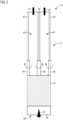
- FIG 1 shows a schematic flow diagram for a process for ammonia synthesis by means of a reaction device 10, which comprises a reactor device 12 and condensation devices 16.
- feed gas 14 which comprises at least nitrogen and hydrogen as reactants, is passed through an inlet opening under pressure into a reaction chamber 32 of the reactor devices 12 over or onto a catalyst 66, whereby ammonia is formed as a product in chemical equilibrium.
- the ammonia in particular in gaseous form, forms a wet gas 19 together with the residues of the feed gas 14 or with any other by-products formed therefrom. However, no by-products are generally formed.
- wet gas describes that it contains at least one product that is to be condensed out.
- the wet gas from the reactor device is fed into a condensation device 16, which has at least three monolithic heat exchange units formed one after the other or one after the other, and in which the ammonia as a product of the introduced gas is condensed as condensate 20.
- the first heat exchange unit 24 is operated as a countercurrent cooler, whereby the wet gas 19 exchanges heat with dry gas 22 or residual gas from which ammonia has already condensed.
- the second heat exchange unit 26 is operated as a condenser, whereby the gaseous reactants or the gaseous fluid are separated from the liquid pressurized condensate 20.
- the third heat exchange unit 28 is operated as an aftercooler and thereby subcools or further cools the pressurized condensate 20, in particular to room temperature.
- This subcooled condensate 20 is discharged via a collecting channel 30, and the dry gas 22 is discharged via an outlet opening.
- the condensation device 16 in particular monolithically with the reactor device 12 (see FIG 4 ) is formed, which comprises a preheating unit 36, which is formed in particular by a first reactor 34 surrounded by a heat pipe temperature control unit. This allows the feed gas 14 to be preheated.
- the reaction chamber 32 contains the preheating unit 36 and a second reactor 35 surrounded by a heat exchange reservoir 38, which is advantageously designed as a heat pipe heat exchange reservoir, and the first reactor 34 surrounded by a heat recovery reservoir 40, which is advantageously designed as a heat pipe heat recovery reservoir.
- the feed gas 14 is preheated and reacted.
- the reaction chamber 32 is delimited by or formed by a pressure vessel, so that the feed gas 14 can be introduced into the reaction chamber 32 at a particularly high pressure, at least 400 and in particular 500 bar.
- the feed gas 14, before reaching the preheating unit 36 must have a temperature of 50°C, with the hydrogen content being 75% and the nitrogen content being 25%.
- an ionic compressor can advantageously be provided, which thus provides 500 bar compression technology, particularly for small systems, such as the reaction device 10.
- the temperature of the feed gas 14 is heated to 400°C or at least 350°C by means of a cooling medium, such as cooling water or naphthalene, which is cyclically evaporated and condensed in the heat pipe temperature control unit.
- a cooling medium such as cooling water or naphthalene
- the wet gas 19 also has a temperature of at least 350°C.
- the wet gas 19 is then fed into the condensation device 16.
- the first heat exchange unit 24 there is operated as a counterflow cooler, so that the wet gas 19 flows through a first plate channel 44 to the second heat exchange unit 26 for phase separation and then flows back as dry gas 14 in an adjacent plate channel 44 to the end of the first heat exchange unit 24 facing away from the second heat exchange unit 26.
- the dry gas 22 leaves the condensation device 16 at a temperature of 350 °C, for example, by being discharged via a vent opening or, in an advantageous embodiment, is fed directly into a further reaction device 10 or reactor device 12, for example in order to carry out several cascading reactor runs or To enable consecutive reaction runs. This is described in FIG 6 taken a closer look.
- the second heat exchange unit 26 serves as a condenser in which the condensate 20 is separated from the gas, this taking place at a temperature of, for example, 30 °C and the second heat exchange unit 26 can thus be used or is used as a cooler and phase separator 64.
- a heat sink 18, the heat exchange reservoir 38, and the heat recovery reservoir 40 symbolize the operating temperature specified by the respective cooling medium or cooling liquid.
- the heat exchange unit 28 is cooled by means of a further cooling medium, enabling particularly advantageous subcooling of the condensate 20 to, for example, 14 °C or room temperature.
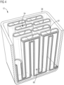
- FIG 2 shows a schematic perspective view of a condensation device 16 for a reaction device 10 presented here for carrying out the process presented here.
- FIG 2 the condensation device 16 without a housing or wall, which in particular forms a further pressure vessel.
- the condensation device 16 comprises at least three heat exchange units 24, 26, 28 formed together, of which the first heat exchange unit 24 is designed as a counterflow cooler, the second heat exchange unit 26 as a condenser, and the third heat exchange unit 28 as an aftercooler.
- the first heat exchange unit 24 is formed by a plurality of solid plates 42 arranged parallel to one another and spaced apart, wherein two adjacent plates 42 each form a plate channel 44, which is each axially oriented essentially along a condensation direction 54 and the plate channels 44 are alternately open, so that via the respective plate channel 44, which extends into the second heat exchange unit 26 extends, since the second heat exchange unit 26 is designed such that the respective first plates 42 are seamlessly continued by porous demister plates 46, phase separation is possible in the second heat exchange unit, and the alternating opening of the plate channels 44 thus allows the first heat exchange unit 24 to be operated as a counterflow cooler.
- the third heat exchange unit 28 is formed from alternating solid plates 48 and porous collecting plates 50, which are arranged essentially perpendicular to the plates 42 and 46 of the first and second heat exchange units 24 and 26.
- the third heat exchange unit 28 comprises at least one cooling channel 52 and the collecting channel 30 for the condensate 20, which is located in an end region 56, in particular in the condensation direction 54.
- FIG 3 shows a schematic sectional view of a section of the condensation device 16, showing the transition from the solid plates 42 to the porous demistor plates 46, so that adjacent plate channels 44 serve for the inflow of the feed gas 14 and the outflow of the dry gas 22.
- the condensate 20 is discharged via the collecting channel 30, while it is further cooled by the third heat exchange unit 28.
- the porous material of the porous demistor plates 46 merges into the porous material of the porous collecting plates 50, which are each surrounded by the intervening solid cooling plates - the plates 48 - for particularly advantageous cooling.
- a material of the condensation device 16 is particularly stable in the long term against high pressure and/or high temperatures and/or ammonia and/or hydrogen and/or nitrogen, so that the reaction device 10 can be designed to be particularly durable.
- the material comprises, for example, the alloy IN625 and/or IN718, the former having a thermal conductivity of, for example, 10 W/(m*K), whereby a temperature gradient, in particular along the condensation direction 54, so that a temperature gradient can be formed, in particular due to the thin wall thickness of the plates 42 and 46 and thus axially or in the condensation direction 54.
- FIG 4 shows a schematic perspective view of a preheating unit 36, which is formed by a first reactor 34 surrounded by a heat pipe temperature control unit.
- the reactants or the feed gas 14 are conveyed through tubes of the first reactor 34 towards or to the condensation device 16 and are preheated by a cooling medium, which is represented, for example, by the heat exchange reservoir 38 or heat recovery reservoir 40.
- a cooling medium which is represented, for example, by the heat exchange reservoir 38 or heat recovery reservoir 40.
- Naphthalene for example, can be used as the cooling medium in the heat pipe temperature control unit. This is passed through the heat pipes of the heat pipe temperature control unit at, for example, 400°C and accordingly heats the feed gas introduced, for example, at 50°C, to 350°C to 400°C for the condensation device 16.
- FIG 5 shows a schematic flow diagram for the process in which the starting materials are provided and fed to the reaction device 10. Hydrogen H 2 is obtained via an electrolyzer 58, which is supplied with electricity 60, wherein the electrolyzer 58 is advantageously coupled to the heat recovery reservoir 40 or at least has the same temperature.
- Both nitrogen and hydrogen are conveyed to the reaction device 10 by means of compressors 62.
- FIG 6 shows several jointly formed reaction devices 10, each with a condensation device 16 and a reactor device 12, which are connected in series so that several reactor runs or runs of the process can be carried out in a cascade one after the other.
- FIG 6 is indicated by "[...]” that virtually any number of further reaction devices 10 can be arranged between the first and the last reaction device 10. For example, five reaction devices 10 can be connected in series, and condensate 20 can be discharged from each of them, with the dry gas 22 discharged from the upstream condensation device 16 serving as feed gas 14 for the next reactor device 12.
- the reaction device 10 thus provides a highly integrated reactor, which can be manufactured, for example, by additive manufacturing, in particular by powder bed fusion. Additive manufacturing results in particularly high structural strength and a favorable geometry for thermal conductivity and heat integration, particularly for the condensation device 16.
- the reaction device 10 enables an advantageous bundling of complexity for the ammonia synthesis, in particular by cascading several reactor devices 12 and condensation devices 16, as well as by the possibility of a common heat exchange, for example via the heat sink 18, the heat exchange reservoir 38 and the heat recovery reservoir 40, whereby a product condensation of the condensate 20 is particularly advantageously enabled, in particular in several stages.
- the two reaction zones or reactors 34 and 35 make it possible to achieve high conversions (higher temperature, faster conversion) while still promoting chemical equilibrium (lower temperature, residual conversion until equilibrium).
- High-temperature heat is transferred to the useful heat system via the heat pipes of the heat pipe temperature control unit, which is used to preheat the feed gas or feed gas 14. From an exergetic perspective, it may be advantageous to initially utilize the lower temperature level of, for example, 350 °C of the second reaction zone and further heat it with reaction heat, and then extract it from the first reaction zone at a higher temperature as useful heat.
- a heat exchanger is enabled, in particular, via the first heat exchange unit 24 to prevent heat loss. Condensation in the second heat exchange unit 26 and subcooling of the pressurized condensate 20 in the third heat exchange unit 28 to room temperature are enabled.
- the IN625 alloy conducts heat particularly poorly for a metallic material.
- Long components with thin walls in the direction of the temperature gradient therefore lose very little heat axially and are capable of establishing a temperature gradient.
- Thin plates, such as plates 42 and 46, still exchange sufficient heat radially despite their poor thermal conductivity.
- a compressor with ionic liquid which can, for example, also produce small quantities of 18 kg of hydrogen per hour at a pressure of 500 bar, for example in compact 10 t container units.
- At least one of the compressors 62 can be designed as an ionic compressor.
- the reactor system or the first reactor 34 in the heat bath of the heat pipe cooler can, for example, be operated particularly efficiently due to additive manufacturing, since, for example, functional elements can be manufactured simultaneously without additional effort.
- the ammonia product or the condensate 20 can each be condensed in the respective condensation device 16, whereby only the essential heat loss via axial heat conduction or along the condensation direction 54 in the respective condensation device 16 and the heat released during condensation and subcooling flow into the cooling water.
- the heat in the hot product stream i.e. from the respective feed gas 14, is used to heat the residual gas coming from the condenser. Useful heat is extracted, in particular, at 400 °C.
- the process and reaction device 10 presented here offer several advantages. Compared to conventional ammonia synthesis, the process presented here offers several benefits that are particularly relevant in the context of decentralized renewable energies.
- the chemical equilibrium can shift into an attractive range when operating at very high pressure.
- conversions of, for example, 60% can be achieved even at 400 °C, with a high reaction rate and the use of little catalyst.
- Temperatures between 200 °C and 330 °C are common in large-scale industrial plants, with a much lower reaction rate.
- the isothermal nature of the reaction device 10 ensures controllability and precisely predictable behavior (without hot spots/cold spots).
- the isothermal nature of the reactor also enables precise operation of the catalyst without damage.
- the reaction device 10 can be constructed particularly compactly, enabling heating and cooling with particularly low energy consumption, and keeping it warm even when not in operation with only minimal thermal loss.
- the reaction device 10 is monolithic, particularly manufactured from a high-performance alloy, and is therefore a material system that is very resistant and tough even at high temperatures and, moreover, very corrosion-resistant, yet small structures can still be precisely formed.
- the isothermal nature of the process and thus in the reaction device 10 can be achieved using molten salt or a heat pipe temperature control unit, for example, with naphthalene as the working medium, which can be operated up to approximately 450°C.
- Heat efficiency so that only small amounts of heat are released into cold cooling water, where they are lost for use. Heat is released in the system or reaction device 10 according to exergetic considerations only at the required temperature level. High-temperature heat is extracted and can be used. This allows for yields of more than 95% without a cycle gas compressor, with only the cold gas being compressed. Exergetic efficiency, for example, results in a robust eco-design.
- the process is also easy to implement and operate the reaction device 10, since, for example, few connecting lines are required, no seals are required and therefore no leakage risks are eliminated at the transition between individual heat exchange units 24, 26, 28 and the preheating unit 36.
- additive manufacturing can also be used to machine a high-performance alloy such as IN625 with the required fragility, thus enabling a particularly compact design and, compared to conventional systems where reactors can have a diameter of 4 m, for example, a high pressure of 500 bar at 500 °C can be achieved.
- the condensation device 16 allows for the realization of a multifunctional monomaterial (multifunctional monomaterial), making the reaction device 10 particularly easy to recycle.
- a closed metabolic cycle for reactor body dismantling which is particularly desirable for high-quality alloys, can be easily enabled.
- an ionic compressor is particularly efficient, and decentralized heat utilization is possible.
- Renewable energy generated in a decentralized manner over a large area can be used particularly advantageously by the method and reaction device 10 presented, so that, for example, a decentralized production of fertilizers without CO2 release is made possible.
Landscapes
- Chemical & Material Sciences (AREA)
- Organic Chemistry (AREA)
- Chemical Kinetics & Catalysis (AREA)
- Analytical Chemistry (AREA)
- Inorganic Chemistry (AREA)
- Physical Or Chemical Processes And Apparatus (AREA)
- Devices And Processes Conducted In The Presence Of Fluids And Solid Particles (AREA)
Abstract
Die Erfindung betrifft ein Verfahren zur Ammoniaksynthese mit einer Reaktionsvorrichtung (10) in deren Reaktoreinrichtung (12) Speisegas (14), welches zumindest Stickstoff und Wasserstoff als Edukte umfasst, über eine Einlassöffnung unter Druck über einen Katalysator (60) geleitet wird, wobei Ammoniak als Produkt gebildet wird.

Description
Die Erfindung betrifft ein Verfahren zur Ammoniaksynthese mittels einer Reaktionsvorrichtung gemäß dem Patentanspruch 1. Ferner betrifft die Erfindung eine korrespondierende Reaktionsvorrichtung gemäß dem Patentanspruch 6.The invention relates to a process for ammonia synthesis by means of a reaction device according to claim 1. Furthermore, the invention relates to a corresponding reaction device according to claim 6.
Ammoniak, welches die chemische Formel NH3 aufweist, ist eine besonders wichtige Grundchemikalie und wurde beispielsweise im Jahr 2020 in der Größenordnung von 140 Millionen Tonnen hergestellt. Ausgangsstoffe für das vor rund 120 Jahren erfundene Haber-Bosch-Verfahren, welches das Standardverfahren zur Ammoniaksynthese darstellt, sind Wasserstoff (H2) und Stickstoff (N2).Ammonia, which has the chemical formula NH 3 , is a particularly important basic chemical and, for example, was produced on the order of 140 million tons in 2020. The starting materials for the Haber-Bosch process, invented around 120 years ago and which represents the standard process for ammonia synthesis, are hydrogen (H 2 ) and nitrogen (N 2 ).
Ammoniak entsteht dabei in einer Gleichgewichtsreaktion aus den Elementen Wasserstoff und Stickstoff gemäß der Gleichung:
![]()
![]()
In der Regel wird der benötigte Stickstoff der Umgebungsluft entnommen, wobei der in der Luft enthaltene Sauerstoff beispielsweise abgeschieden und der Stickstoff durch Luftzerlegungsverfahren aufgereinigt wird. Der Wasserstoff wird als energiehaltiger Ausgangsstoff der Ammoniaksynthese bereits seit hundert Jahren fast ausschließlich durch fossile Energieträger bereitgestellt.Typically, the required nitrogen is extracted from the ambient air, with the oxygen contained in the air being separated, for example, and the nitrogen being purified using air separation processes. Hydrogen, the energy-rich starting material for ammonia synthesis, has been supplied almost exclusively by fossil fuels for a hundred years.
Folgeprodukte, bei denen Ammoniak als Ausgangsstoff dient, sind beispielsweise Harnstoff, Ammonium- und Nitrat-Düngemittel, wobei über 80 % der Weltproduktion von Ammoniak für Düngemittel verwendet werden. Ferner sind vielfältigste chemische Produkte, beispielsweise Polyamide für Textilfasern, Kunststoffe und Werkstoffe, Duroplast-Melaminharze, Sprengstoffe, Reduktionsmittel in der Rauchgasentstickung und so weiter auf Ammoniakbasis erzeugt. Des Weiteren wird NH3 als Wasserstoffspeichersubstanz und auch als Energieträger diskutiert.Derivative products using ammonia as a starting material include urea, ammonium, and nitrate fertilizers, with over 80% of global ammonia production being used for fertilizers. Furthermore, a wide variety of chemical products are used, such as polyamides for textile fibers, plastics and materials, thermoset melamine resins, explosives, reducing agents in flue gas denitrification, and and so on, based on ammonia. NH 3 is also being discussed as a hydrogen storage substance and as an energy carrier.
Für die Ammoniaksynthese werden derzeit fast 2 % aller fossilen Energieträger verbraucht. Ebenso entstammen aus der Ammoniakherstellung etwa 500 Millionen Tonnen CO2, was ca. 2 % der anthropogenen CO2-Emission aus Energieträgern entspricht, was für ein einziges Produktmolekül durchaus bemerkenswert viel ist.Ammonia synthesis currently consumes almost 2% of all fossil fuels. Ammonia production also generates approximately 500 million tons of CO2 , which corresponds to approximately 2% of anthropogenic CO2 emissions from energy sources—a remarkable amount for a single product molecule.
Wünschenswert wäre, grünen Ammoniak ohne Treibhausgasemission herzustellen, was bereits ein wichtig diskutiertes Thema der chemischen Industrie darstellt, das aufgrund komplexer Anlagen und Betriebskonzepte und ohne bereitstehenden CO2-neutralen, sogenannten grünen, Elektrolysewasserstoff bisher nicht in der Breite realisiert wurde. Klimaneutrales Ammoniak wird sogar als Wasserstoff-Überträgersubstanz zwischen Australien und Europa als Kraftstoff für Containerschiffe diskutiert, wodurch eine erhebliche CO2-Reduktion in der Schifffahrt erreicht werden könnte.It would be desirable to produce green ammonia without greenhouse gas emissions. This is already a hotly debated topic in the chemical industry, but has not yet been widely implemented due to complex plant and operating concepts and the lack of available CO2 -neutral, so-called green, electrolysis hydrogen. Climate-neutral ammonia is even being discussed as a hydrogen transfer substance between Australia and Europe as a fuel for container ships, which could achieve significant CO2 reductions in shipping.
Eine innovative, vollautomatisierte und fluktuierend betriebene sogenannte grüne Ammoniakanlage (Green-Ammonia) mit Wasserelektrolyse im dezentralen Elektrizitätsnetz könnte als Energiespeicher oder auch in Verbindung mit entsprechender nachhaltiger Düngemittelsynthese eine attraktive Möglichkeit für eine dezentrale, CO2-freie Ammoniaksynthese sein.An innovative, fully automated and fluctuating green ammonia plant with water electrolysis in the decentralized electricity grid could be an attractive option for decentralized, CO2 -free ammonia synthesis as an energy storage facility or in conjunction with appropriate sustainable fertilizer synthesis.
Wirtschaftliche, technologische und betriebstechnische Gründe gegen die Verwendung von Wasserstoff aus erneuerbaren Energien in der Ammoniaksynthese sind derzeit:
Die Dezentralität: da kleine Anlagen in der Regel eine besonders geringe Menge an Endprodukten im Vergleich zu Fertigungskosten bedeuten; die Fluktuation: da Wasserstoff aus erneuerbaren Energien in der Regel nur unstet zur Verfügung steht und ohne Speicherung kein kontinuierlicher Betrieb der Ammoniaksynthese möglich ist; die Automatisierung: kleine unkonventionelle Anlagen sind in der Regel nicht vollautomatisch und dadurch im Betrieb aufgrund von Personalkosten zu teuer; die Effizienz: Ammoniaksynthese ist begünstigt von hohem Druck, der kostengünstig bereitgestellt werden muss. Darüber hinaus sind großtechnische Prozesse im kleinen Maßstab stets kompliziert.Economic, technological and operational reasons against the use of hydrogen from renewable energies in ammonia synthesis are currently:
Decentralization: because small plants usually mean a particularly small amount of end products compared to production costs; fluctuation: because hydrogen from renewable energies is usually only available intermittently and without storage, continuous operation of the Ammonia synthesis is possible; automation: small, unconventional plants are generally not fully automated and therefore too expensive to operate due to personnel costs; efficiency: ammonia synthesis benefits from high pressure, which must be provided cost-effectively. Furthermore, large-scale industrial processes are always complicated.
Aufgabe der vorliegenden Erfindung ist es, ein Verfahren sowie eine Reaktionsvorrichtung zur Ammoniaksynthese bereitzustellen, welche besonders gut, insbesondere hinsichtlich kleiner Anlagen, skalierbar ist und darüber hinaus besonders effizient ist.The object of the present invention is to provide a process and a reaction device for ammonia synthesis which is particularly well scalable, especially with regard to small plants, and is also particularly efficient.
Diese Aufgabe wird erfindungsgemäß durch die Gegenstände der unabhängigen Patentansprüche gelöst. Vorteilhafte Ausgestaltungen und Weiterbildungen sind in den übrigen Ansprüchen, der Beschreibung sowie in den Figuren gezeigt.This object is achieved according to the invention by the subject matter of the independent patent claims. Advantageous embodiments and further developments are shown in the remaining claims, the description, and the figures.
Ein erster Aspekt der Erfindung betrifft ein Verfahren zur Ammoniaksynthese mittels einer Reaktionsvorrichtung.A first aspect of the invention relates to a process for ammonia synthesis by means of a reaction device.
Bei dem erfindungsgemäßen Verfahren wird zur Abtrennung des NH3-Produkts gasförmiges Fluid beziehungsweise Speisegas, welches zumindest N2 und H2 beziehungsweise Stickstoff und Wasserstoff als Edukte umfasst, über eine Einlassöffnung in eine Reaktoreinrichtung der Reaktionsvorrichtung unter Druck über einen Katalysator geleitet, wobei Ammoniak als Produkt gebildet wird und dieses gasförmig insbesondere mit weiteren Produkten als nasses Gas hin zu einer Kondensationseinrichtung, die zumindest drei monolithisch miteinander beziehungsweise insbesondere entlang einer Kondensationsrichtung nacheinander ausgebildete Wärmetauscheinheiten aufweist, geleitet wird, um diese zu durchströmen, wobei das Ammoniak NH3 als Produkt aus dem eingeleiteten, insbesondere nassen Gas als Kondensat kondensiert wird. Dazu wird die erste Wärmetauscheinheit als Gegenstromkühler beziehungsweise im Englischen Feed-Effluent-Exchanger betrieben, wodurch das Speisegas mit trockenem Gas beziehungsweise Restgas, aus welchem bereits Ammoniak auskondensiert ist, Wärme tauscht, und die zweite Wärmetauscheinheit, welche insbesondere nahtlos an die erste Wärmetauscheinheit grenzt beziehungsweise diese funktional verlängert, als Kondensor betrieben wird, wodurch die gasförmigen Edukte vom flüssigen unter Druck stehenden Kondensat beziehungsweise Produkt getrennt werden, und die dritte Wärmetauscheinheit als Nachkühler betrieben wird und dadurch das unter Druck stehende Kondensat unterkühlt wird, welches, insbesondere bei Raumtemperatur, über einen Sammelkanal abgeführt wird und ferner das trockene Gas beziehungsweise Restgas über eine Auslassöffnung aus der Reaktionsvorrichtung abgeführt wird.In the process according to the invention, for the separation of the NH 3 product, gaseous fluid or feed gas, which comprises at least N 2 and H 2 or nitrogen and hydrogen as reactants, is passed through an inlet opening into a reactor device of the reaction apparatus under pressure over a catalyst, wherein ammonia is formed as a product and this is passed in gaseous form, in particular with other products, as a wet gas, to a condensation device which has at least three heat exchange units formed monolithically with one another or in particular one after the other along a condensation direction, in order to flow through them, wherein the ammonia NH 3 as a product from the introduced, in particular wet gas, is condensed as condensate. For this purpose, the first heat exchange unit is operated as a countercurrent cooler or feed-effluent exchanger, whereby the feed gas with dry gas or residual gas from which ammonia has already condensed, and the second heat exchange unit, which in particular borders seamlessly on the first heat exchange unit or functionally extends it, is operated as a condenser, whereby the gaseous reactants are separated from the liquid pressurized condensate or product, and the third heat exchange unit is operated as an aftercooler and thereby the pressurized condensate is subcooled, which, in particular at room temperature, is discharged via a collecting duct and furthermore the dry gas or residual gas is discharged from the reaction device via an outlet opening.
Die monolithische Kondensationseinrichtung kann insbesondere mittels additiver Fertigung ausgebildet beziehungsweise gefertigt oder hergestellt sein. Aufgrund der kompakten und somit zusammenliegenden unterschiedlichen funktionalen Einheiten - den Wärmetauscheinheiten - ergibt sich eine besondere Strukturfestigkeit und aufgrund der Geometrie eine gewünschte Leitfähigkeit beziehungsweise Wärmeintegration insbesondere bei einer exergetischer Optimierung, sodass beispielsweise ein geringer Abfluss von Abwärme ins Kühlwasser ermöglicht werden kann.The monolithic condensation device can be designed, manufactured, or produced, in particular, using additive manufacturing. The compact and thus adjacent different functional units—the heat exchange units—result in particular structural strength, and the geometry provides the desired conductivity or heat integration, particularly with exergetic optimization, enabling, for example, a low outflow of waste heat into the cooling water.
So sind mit anderen Worten insbesondere mehrere Wärmetauscher und ein Phasenabscheider, welcher insbesondere im Übergangsbereich der zweiten und dritten Wärmetauscheinheit durch diese ausgebildet ist, aus einem insbesondere mittels additiver Fertigung und/oder zumindest einen teilweise metallischen Werkstoff aufweisenden Block gebildet. Die Ammoniaksynthese mittels des erfindungsgemäßen Verfahrens ist eine Gleichgewichtsreaktion, wobei sich das chemische Gleichgewicht insbesondere bei hohem Druck in einen attraktiven Bereich verschiebt. So kann beispielsweise selbst bei 400 °C eine hohe Reaktionsgeschwindigkeit und zugleich durch 500 bar (50 MPa) Druck eine akzeptable Gleichgewichtslage erzielt werden, wodurch besonders wenig Katalysator verwendet werden kann.In other words, in particular, several heat exchangers and a phase separator, which is formed by the second and third heat exchange units, in particular in the transition region of the latter, are formed from a block, in particular by additive manufacturing and/or comprising at least a partially metallic material. Ammonia synthesis using the process according to the invention is an equilibrium reaction, with the chemical equilibrium shifting into an attractive range, particularly at high pressure. For example, a high reaction rate can be achieved even at 400 °C, while at the same time an acceptable equilibrium position can be achieved at 500 bar (50 MPa) pressure, allowing the use of a particularly small amount of catalyst.
Dabei können Umsätze von beispielsweise 60 % erreicht werden, was gegenüber konventionellen Prozessverfahren, welche üblicherweise bei 200 bar und 330 °C stattfinden, eine viel höhere Reaktionsrate und Produktausbeute aufgrund des chemischen Gleichgewichts ermöglicht. So ist ein Vorteil des Verfahrens eine besonders hohe Effizienz bei der Ammoniaksynthese.Conversion rates of, for example, 60% can be achieved, which, due to the chemical equilibrium, allows for a much higher reaction rate and product yield compared to conventional processes, which typically take place at 200 bar and 330 °C. One advantage of the process is its particularly high efficiency in ammonia synthesis.
Um die Synthese besonders vorteilhaft durchzuführen, ist in einer Ausgestaltung der Erfindung vorgesehen, dass die Reaktoreinrichtung einen insbesondere monolithisch mit der Kondensationseinrichtung ausgebildeten Reaktionsraum aufweist, welcher durch eine Vorwärmeeinheit und einen zweiten Reaktor umgeben von einem Heatpipe-Wärmeaustauschreservoir sowie durch einen ersten Reaktor umgeben von einem Heatpipe-Wärmegewinnungsreservoir , welches beispielsweise mit Naphthalin bis ca. 430 °C betrieben wird, ausgebildet ist, durch welchen das gasförmige Fluid beziehungsweise Speisegas vorgewärmt und zur Reaktion gebracht wird. Mit anderen Worten ist eine erste Reaktionszone vorgesehen, welche sich vorteilhaft durch Röhren in einem Wärmebad gebildet ist. So kann Hochtemperaturwärme beispielsweise in ein Nutzwärmesystem, das zum Vorheizen des nassen Gases beziehungsweise Feedgases genutzt wird, abgegeben werden. Dadurch ergibt sich der Vorteil, dass dies besonders exergetisch günstig ist, so kann beispielsweise zunächst das geringe Temperaturniveau von beispielsweise 350 °C genutzt werden, um mit Reaktionswärme weiter aufzuheizen und beispielsweise über die Heatpipes bei höheren Temperaturen als die Nutzwärme auszukoppeln.In order to carry out the synthesis particularly advantageously, one embodiment of the invention provides that the reactor device has a reaction chamber which is in particular monolithic and formed with the condensation device and which is formed by a preheating unit and a second reactor surrounded by a heat pipe heat exchange reservoir and by a first reactor surrounded by a heat pipe heat recovery reservoir which is operated, for example, with naphthalene up to approx. 430 °C, through which the gaseous fluid or feed gas is preheated and reacted. In other words, a first reaction zone is provided which is advantageously formed by tubes in a heat bath. For example, high-temperature heat can be released into a useful heat system which is used to preheat the wet gas or feed gas. This has the advantage that this is particularly exergetically favorable; for example, the low temperature level of, for example, 350 °C can be used initially to further heat up using reaction heat and, for example, to extract it via the heat pipes at higher temperatures than the useful heat.
In weiterer vorteilhafter Ausgestaltung der Erfindung ist der Reaktionsraum durch einen Druckbehälter gebildet beziehungsweise von einem Druckbehälter umschlossen und somit von diesem begrenzt, sodass das gasförmige Fluid beziehungsweise Speisegas mit wenigstens 300 und insbesondere 400 bar und besonders bevorzugt 500 bar in den Reaktionsraum eingeleitet wird beziehungsweise werden kann. Mit anderen Worten ist die Reaktionsvorrichtung so ausgelegt, dass die Reaktion beziehungsweise das Kondensieren unter einem besonders hohen Druck, welcher über 300 bar liegt und vorteilhafterweise 500 bar ist, durchgeführt werden kann. Dadurch ergibt sich der Vorteil, dass eine besonders hohe Reaktionsausbeute ermöglicht wird.In a further advantageous embodiment of the invention, the reaction chamber is formed by a pressure vessel or enclosed by a pressure vessel and thus delimited by it, so that the gaseous fluid or feed gas is or can be introduced into the reaction chamber at at least 300 and in particular 400 bar and particularly preferably 500 bar. In other words, the reaction device is designed such that the reaction or condensation takes place under a particularly high Pressures above 300 bar, and preferably 500 bar, can be carried out. This has the advantage of enabling a particularly high reaction yield.
In weiterer vorteilhafter Ausgestaltung der Erfindung wird der Druck des Speisegases mittels eines ionischen Verdichters beziehungsweise eines Verdichters mit ionischer Flüssigkeit erzeugt. Mit anderen Worten wird ein isotherm arbeitender Verdrängungsprozessor, welcher durch eine ionische Flüssigkeit bei der Verdichtung entstehende Wärme im Inneren abführen kann, verwendet, um das trockene Gas beziehungsweise Feedgas zu verdichten. Dabei ergibt sich der Vorteil, dass auf besonders vorteilhafte Weise das Gas mit besonders hohen Drücken und dabei besonders effizient komprimiert werden kann.In a further advantageous embodiment of the invention, the pressure of the feed gas is generated by means of an ionic compressor or a compressor with ionic liquid. In other words, an isothermal displacement processor, which can dissipate the heat generated during compression by an ionic liquid, is used to compress the dry gas or feed gas. This results in the advantage that the gas can be compressed at particularly high pressures and particularly efficiently.
In weiterer Ausgestaltung der Erfindung können mehrere Reaktionsläufe in einer Kaskade hintereinander durchgeführt werden beziehungsweise erfolgen, wobei dazu insbesondere eine korrespondierende Anzahl an Reaktionsvorrichtungen, insbesondere monolithisch gefertigt, in Reihe geschaltet sind. Dabei umfasst vorteilhafterweise die jeweilige Reaktoreinrichtung der jeweiligen Reaktionsvorrichtung ein jeweiliges Wärmeaustauschreservoir mit Vorwärmeeinheit und zweitem Reaktor beziehungsweise ist mit diesen zusammen ausgebildet. Mit anderen Worten kann die Reaktionsvorrichtung mehrere Reaktoreinrichtungen und Kondensationseinrichtungen aufweisen, welche fluidisch leitend in Reihe geschaltet sind, sodass aus einer in Strömungsrichtung des Fluids zuerst angeordneten Kondensationseinrichtung ausströmendes trockenes Gas als quasi Speisegas beziehungsweise Feedgas in die nächste Reaktoreinrichtung strömt. So kann beispielsweise über eine Zwischenkondensation eine besonders hohe Ausbeute ermöglicht werden, weil jeweils Ammoniak dem Gleichgewicht entzogen werden kann. Durch die Kaskade kann das Produkt beziehungsweise Ammoniak jeweils bei jedem Durchlauf auskondensieren, wobei insbesondere nur nicht verzichtbaren Wärmeverluste, insbesondere bei einer axialen Wärmeleitung (in der jeweiligen Kondensationseinrichtung) die bei der Kondensation unter Kühlung freiwerdende Wärme ins Kühlwasser abfließt. Die Wärme im insbesondere heißen Produktstrom des Speisegases wird zum Aufheizen des aus dem Kondensator kommenden Restgases benutzt. Nutzwärme kann bei 400 °C aus dem Wärmegewinnungsreservoir des ersten Reaktors ausgekoppelt werden. Dadurch ergibt sich der Vorteil, dass eine besonders hohe Ammoniakausbeute erzielt werden kann.In a further embodiment of the invention, several reaction runs can be carried out or take place in a cascade one after the other, wherein for this purpose, in particular a corresponding number of reaction devices, in particular monolithically manufactured, are connected in series. In this case, the respective reactor device of the respective reaction device advantageously comprises a respective heat exchange reservoir with a preheating unit and a second reactor or is designed together with these. In other words, the reaction device can have several reactor devices and condensation devices which are connected in series in a fluidically conductive manner, so that dry gas flowing out of a condensation device arranged first in the flow direction of the fluid flows into the next reactor device as a quasi feed gas or feed gas. For example, an intermediate condensation can enable a particularly high yield because ammonia can be removed from the equilibrium in each case. The cascade allows the product or ammonia to condense out in each run, wherein in particular only indispensable heat losses, in particular An axial heat pipe (in the respective condensation device) allows the heat released during condensation to flow into the cooling water. The heat in the particularly hot feed gas product stream is used to heat the residual gas coming from the condenser. Useful heat can be extracted from the heat recovery reservoir of the first reactor at 400 °C. This has the advantage of allowing a particularly high ammonia yield to be achieved.
Ein zweiter Aspekt der Erfindung betrifft eine Reaktionsvorrichtung für ein Verfahren gemäß dem ersten Aspekt der Erfindung. Die erfindungsgemäße Reaktionsvorrichtung umfasst eine Reaktoreinrichtung, welche insbesondere eine Vorwärmeeinheit, einen ersten Reaktor und einen zweiten Reaktor aufweist, sowie eine Kondensatoreinrichtung, welche wenigstens drei monolithisch miteinander beziehungsweise nacheinander ausgebildete Wärmetauscheinheiten aufweist, welche insbesondere funktional ineinander übergehen, wobei von den Wärmetauscheinheiten die erste Wärmetauscheinheit als Gegenstromkühler beziehungsweise Feed-Effluent-Tauscher, die zweite Wärmetauscheinheit als Kondensor und die dritte Wärmetauscheinheit als Nachkühler ausgebildet sind, wobei insbesondere die zweite und teilweise die dritte Wärmetauscheinheit zusammen einen Phasenabscheider bilden, welcher dazu dient, das Kondensat des Ammoniaks aus dem Gas abzuscheiden.A second aspect of the invention relates to a reaction device for a process according to the first aspect of the invention. The reaction device according to the invention comprises a reactor device, which in particular has a preheating unit, a first reactor and a second reactor, and a condenser device, which has at least three heat exchange units formed monolithically with one another or one after the other, which in particular functionally merge into one another, wherein of the heat exchange units, the first heat exchange unit is designed as a counterflow cooler or feed-effluent exchanger, the second heat exchange unit as a condenser and the third heat exchange unit as an aftercooler, wherein in particular the second and partly the third heat exchange unit together form a phase separator which serves to separate the condensate of the ammonia from the gas.
Dabei sind Vorteile, vorteilhafte Ausgestaltungen und Weiterbildungen des ersten Aspekts der Erfindung als Vorteile, vorteilhafte Ausgestaltungen und Weiterbildungen des zweiten Aspekts der Erfindung anzusehen und umgekehrt.Advantages, advantageous embodiments and further developments of the first aspect of the invention are to be regarded as advantages, advantageous embodiments and further developments of the second aspect of the invention and vice versa.
In vorteilhafter Ausgestaltung der Erfindung ist die erste Wärmetauscheinheit, welche insbesondere als Gegenstromkühler ausgebildet ist, durch mehrere zu einander parallel beabstandet angeordnete massive Platten ausgebildet, wobei jeweils zwei benachbarte Platten jeweils einen, insbesondere entlang einer Kondensationsrichtung orientierten Plattenkanal ausbilden. Dabei sind benachbarte Plattenkanäle insbesondere wechselseitig geöffnet. Zusätzlich ist die zweite Wärmetauscheinheit durch poröse Demistorplatten ausgebildet, welche jeweils die Platten der ersten Wärmetauscheinheit nahtlos fortführen beziehungsweise in diese übergehen, jedoch beispielsweise einen Umfang oder dergleichen ändern können. Zusätzlich ist die dritte Wärmetauscheinheit, welche insbesondere als Kondensatkühler ausgebildet ist, aus sich abwechselnden aneinanderlegen vollen Platten und porösen Sammelplatten ausgebildet, welche im Wesentlichen senkrecht zu den Platten der ersten und zweiten Wärmetauscheinheit angeordnet sind und wenigstens einen Kühlkanal beziehungsweise wenigstens zwei Kühlkanäle zum Durchströmen von insbesondere kaltem Kühlmittel, und in einem in eine Kondensationsrichtung liegenden Endbereich einen Sammelkanal für das Kondensat aufweisen.In an advantageous embodiment of the invention, the first heat exchange unit, which is designed in particular as a counterflow cooler, is formed by a plurality of solid plates arranged parallel to one another and spaced apart, wherein two adjacent plates each have a plate channel, in particular oriented along a condensation direction form. In this case, adjacent plate channels are in particular open to one another. In addition, the second heat exchange unit is formed by porous demister plates, which each seamlessly continue the plates of the first heat exchange unit or merge into them, but can, for example, change a circumference or the like. In addition, the third heat exchange unit, which is in particular designed as a condensate cooler, is formed from alternating solid plates and porous collecting plates that lie next to one another, which are arranged essentially perpendicular to the plates of the first and second heat exchange units and have at least one cooling channel or at least two cooling channels for the flow of, in particular, cold coolant, and a collecting channel for the condensate in an end region lying in a condensation direction.
Mit anderen Worten ist die Kondensationseinrichtung aus funktional zusammengeschalteten beziehungsweise ineinander übergehenden Wärmetauscheinheiten ausgebildet, sodass insbesondere der poröse Bereich der zweiten und dritten Wärmetauscheinheit, welche nahtlos ineinander übergehen, den Kondensator beziehungsweise Phasenabscheider bildet. Dabei ist je nach Wärmekapazität des verwendeten Werkstoffs, der insbesondere additiv gefertigten Kondensationseinrichtung, über die Kühlkanäle ein Temperaturgradient bis hin zur ersten Wärmetauscheinheit ausbildbar. Durch die abwechselnd geöffneten Platten ergibt sich die Möglichkeit der Gegenstromkühlung beziehungsweise des Feed-Effluent-Kühlers, sodass insbesondere an dem der zweiten und dritten Wärmetauscheinheit gegenüberliegenden Ende in jeweils einen der Plattenkanäle das Speisegas einströmt und durch eine poröse Demistorplatte in der Wärmetauscheinheit in den nächsten benachbarten Plattenkanal strömt und dort das trockene Gas wieder über den Plattenkanal zum oberen Ende der ersten Wärmetauscheinheit ausströmen kann. Dadurch ergibt sich der Vorteil, dass die Reaktionsvorrichtung für einen besonders effizienten Betrieb ausgebildet werden kann. Darüber hinaus ist ein besonders effizientes Durchführen des Verfahrens gemäß dem ersten Aspekt der Erfindung ermöglicht.In other words, the condensation device is formed from functionally interconnected or interleaved heat exchange units, so that in particular the porous region of the second and third heat exchange units, which merge seamlessly into one another, forms the condenser or phase separator. Depending on the heat capacity of the material used, in particular the additively manufactured condensation device, a temperature gradient can be formed via the cooling channels up to the first heat exchange unit. The alternately opened plates result in the possibility of countercurrent cooling or a feed-effluent cooler, so that in particular at the end opposite the second and third heat exchange units, the feed gas flows into one of the plate channels and through a porous demister plate in the heat exchange unit into the next adjacent plate channel, where the dry gas can flow out again via the plate channel to the upper end of the first heat exchange unit. This results in the advantage that the reaction device can be designed for particularly efficient operation. Furthermore, a particularly efficient Carrying out the method according to the first aspect of the invention.
In weiterer vorteilhafter Ausgestaltung der Erfindung weist die Reaktionsvorrichtung mehrere, insbesondere monolithisch miteinander ausgebildete Reaktoreinrichtungen und Kondensationseinrichtungen auf. Zusätzlich oder darüber hinaus ist die jeweilige Kondensationseinrichtung beziehungsweise sind mehrere zusammengefasste beziehungsweise zusammengeflanschte Kondensationseinrichtungen und/oder Reaktoreirichtungen einstückig ausgebildet und/oder additiv gefertigt. Mit anderen Worten wird, um einen besonders geringen Wärmeverlust für das Verfahren zu ermöglichen, mehrere der Kondensationseinrichtungen und Reaktoreinrichtungen zusammengefasst, sodass quasi ohne extra Leitungen, wie beispielsweise Kanäle oder Rohre, ein kaskadiertes Durchführen mehrerer Durchläufe ermöglicht wird. Darüber hinaus kann die jeweilige Kondensationseinrichtung einstückig, das heißt insbesondere nahtlos aus einem Werkstück und dieses insbesondere mittels additiver Fertigung ausgebildet sein. Dadurch ergibt sich der Vorteil, dass beispielsweise ein besonders kostengünstiges Bereitstellen der Reaktionsvorrichtung ermöglicht wird. Darüber hinaus kann auf besonders sichere Weise die Funktionalität beispielsweise der Kondensationseinrichtung bereitgestellt werden.In a further advantageous embodiment of the invention, the reaction device has a plurality of reactor devices and condensation devices, in particular monolithically formed with one another. In addition or in addition, the respective condensation device or a plurality of combined or flanged-together condensation devices and/or reactor devices is formed as a single piece and/or additively manufactured. In other words, in order to enable particularly low heat loss for the process, several of the condensation devices and reactor devices are combined, so that a cascaded implementation of several runs is possible virtually without additional lines, such as channels or pipes. Furthermore, the respective condensation device can be formed as a single piece, i.e. in particular seamlessly from a single workpiece, and this can be formed in particular by means of additive manufacturing. This results in the advantage that, for example, a particularly cost-effective provision of the reaction device is enabled. Furthermore, the functionality of, for example, the condensation device can be provided in a particularly reliable manner.
In weiterer vorteilhafter Ausgestaltung der Erfindung ist ein Werkstoff der (jeweiligen) Reaktoreinrichtung und Kondensationseinrichtung gegenüber Hochdruck und/oder hohe Temperatur und/oder Ammoniak und/oder Wasserstoff und/oder Stickstoff langzeitstabil. Mit anderen Worten wird der Werkstoff, welcher beispielsweise insbesondere eine metallische Legierung ist, derart gewählt, dass die Kondensationseinrichtung und somit die Reaktionsvorrichtung für die Ammoniaksynthese möglichst langlebig ausgebildet werden können. Dadurch ergibt sich der Vorteil, dass beispielsweise ein Verschleiß besonders gering ist, wodurch die Reaktionsvorrichtung beziehungsweise das Verfahren besonders kostengünstig ausgebildet werden können.In a further advantageous embodiment of the invention, a material of the (respective) reactor device and condensation device is long-term stable against high pressure and/or high temperature and/or ammonia and/or hydrogen and/or nitrogen. In other words, the material, which is, for example, in particular a metallic alloy, is selected such that the condensation device and thus the reaction device for ammonia synthesis can be designed to be as durable as possible. This results in the advantage that, for example, wear is particularly low, whereby the reaction device or the process can be designed particularly cost-effectively.
In weiterer vorteilhafter Ausgestaltung der Erfindung umfasst der Werkstoff die Legierung mit der EN-Nummer 2.4856, DIN NiCr22Mo9Nb, auch als Inconel® 625 oder IN625 bezeichnet, und/oder mit der EN-Nummer 2.4668, DIN NiCr19Fe19Nb5Mo3, auch als INCONEL® 718 oder IN718 bezeichnet, und/oder weist der Werkstoff eine Wärmeleitfähigkeit von weniger als 15 und insbesondere 11 W/(m*K) auf, wodurch in der jeweiligen Kondensationseinrichtung entlang der Kondensationsrichtung (beziehungsweise axial) ein Temperaturgradient aufbaubar beziehungsweise ausbildbar ist. Aufgrund beispielsweise der jeweiligen Platten für die jeweiligen Plattenkanäle, welche dünn sind und eine gewisse Länge aufweisen, ist in Richtung des Temperaturgradienten daher ein sehr geringer Wärmeverlust möglich, wobei trotz der schlechten Wärmeleitfähigkeit radial immer noch ausreichend viel Wärme durch die dünnen Platten ausgetauscht werden kann. Mit anderen Worten ist der Werkstoff an einen gewünschten Temperaturgradienten angepasst. Dadurch ergibt sich der Vorteil, dass mit der vorgestellten Reaktionsvorrichtung das Verfahren besonders effizient durchgeführt werden kann.In a further advantageous embodiment of the invention, the material comprises the alloy with the EN number 2.4856, DIN NiCr22Mo9Nb, also referred to as Inconel ® 625 or IN625, and/or with the EN number 2.4668, DIN NiCr19Fe19Nb5Mo3, also referred to as INCONEL ® 718 or IN718, and/or the material has a thermal conductivity of less than 15 and in particular 11 W/(m*K), whereby a temperature gradient can be built up or formed in the respective condensation device along the condensation direction (or axially). Due, for example, to the respective plates for the respective plate channels, which are thin and have a certain length, very little heat loss is possible in the direction of the temperature gradient, whereby despite the poor thermal conductivity, a sufficient amount of heat can still be exchanged radially through the thin plates. In other words, the material is adapted to a desired temperature gradient. This results in the advantage that the process can be carried out particularly efficiently with the reaction device presented.
Für Anwendungsfälle oder Anwendungssituationen, die sich bei dem Verfahren ergeben können und die hier nicht explizit beschrieben sind, kann vorgesehen sein, dass gemäß dem Verfahren eine Fehlermeldung und/oder eine Aufforderung zur Eingabe einer Nutzerrückmeldung ausgegeben und/oder eine Standardeinstellung und/oder ein vorbestimmter Initialzustand eingestellt wird.For use cases or application situations that may arise during the method and which are not explicitly described here, it may be provided that, in accordance with the method, an error message and/or a request to enter user feedback is issued and/or a default setting and/or a predetermined initial state is set.
Unabhängig vom grammatikalischen Geschlecht eines bestimmten Begriffes sind Personen mit männlicher, weiblicher oder anderer Geschlechteridentität mit umfasst.Regardless of the grammatical gender of a particular term, persons with male, female or other gender identity are included.
Es zeigt:
- FIG 1
- ein schematisches Ablaufdiagramm einer Ammoniaksynthese mit einer Reaktionsvorrichtung, welche eine Reaktoreinrichtung und eine Kondensationseinrichtung aufweist;
- FIG 2
- eine schematische Perspektivansicht einer Kondensationseinrichtung der Reaktionsvorrichtung;
- FIG 3
- eine schematische Schnittansicht eines Ausschnitts der Kondensationseinrichtung gemäß
FIG 2 ; - FIG 4
- eine schematische Perspektivansicht einer Reaktoreinrichtung der Reaktionsvorrichtung;
- FIG 5
- ein weiteres schematisches Ablaufdiagramm, welches ein Bereitstellen der Edukte für die Reaktionsvorrichtung beziehungsweise das Verfahren zeigt; und
- FIG 6
- ein weiteres schematisches Ablaufdiagramm des Verfahrens, wobei mehrere Reaktionsdurchläufe kaskadiert hintereinander durchgeführt werden.
- FIG 1
- a schematic flow diagram of an ammonia synthesis with a reaction device which has a reactor device and a condensation device;
- FIG 2
- a schematic perspective view of a condensation device of the reaction apparatus;
- FIG 3
- a schematic sectional view of a section of the condensation device according to
FIG 2 ; - FIG 4
- a schematic perspective view of a reactor device of the reaction apparatus;
- FIG 5
- a further schematic flow diagram showing the provision of the reactants for the reaction device or the process; and
- FIG 6
- another schematic flow diagram of the process, where several reaction runs are carried out in cascaded succession.
Bei dem Verfahren wird in einen Reaktionsraum 32 der Reaktoreinrichtungen 12 Speisegas 14, welches zumindest Stickstoff und Wasserstoff als Edukte umfasst über eine Einlassöffnung unter Druck über beziehungsweise an einen Katalysator 66 geleitet wird, wobei Ammoniak als Produkt im chemischen Gleichgewicht gebildet wird. Das insbesondere gasförmige Ammoniak bildet zusammen mit den Resten des Speisegases 14 beziehungsweise mit gegebenenfalls weiteren daraus gebildeten Nebenprodukten ein nasses Gas 19. In der Regel entstehen jedoch keine Nebenprodukte. Dabei beschreibt der Ausdruck nasses Gas, dass in diesem wenigstens ein Produkt enthalten ist, welches man auskondensieren möchte.In the process, feed
Daher wird bei dem Verfahren das nasse Gas aus der Reaktoreinrichtung in eine Kondensationseinrichtung 16 geleitet, die zumindest drei monolithisch miteinander beziehungsweise nacheinander ausgebildete Wärmetauscheinheiten aufweist, und an der das Ammoniak als Produkt aus dem eingeleiteten Gas als Kondensat 20 kondensiert wird. Dabei wird die erste Wärmetauscheinheit 24 als Gegenstromkühler betrieben, wodurch das nasse Gas 19 mit trockenem Gas 22 beziehungsweise Restgas, aus welchem bereits Ammoniak kondensiert ist, Wärme tauscht. Die zweite Wärmetauscheinheit 26 wird als Kondensor betrieben, wodurch die gasförmigen Edukte beziehungsweise das gasförmige Fluid vom flüssigen unter Druck stehenden Kondensat 20 getrennt werden. Die dritte Wärmetauscheinheit 28 wird als Nachkühler betrieben und dadurch das unter Druck stehende Kondensat 20 unterkühlt beziehungsweise weiter abgekühlt wird, insbesondere auf Raumtemperatur. Diese dieses unterkühlte Kondensat 20 wird über einen Sammelkanal 30 und das trockene Gas 22 über eine Auslassöffnung abgeführt.Therefore, in the process, the wet gas from the reactor device is fed into a
Vorteilhafterweise ist die Kondensationseinrichtung 16 (siehe
Besonders vorteilhaft befindet sich in dem Reaktionsraum 32 die Vorwärmeeinheit 36 und ein zweiter Reaktor 35 umgeben von einem Wärmeaustauschreservoir 38, welches vorteilhaft als Heatpipe-Wärmeaustauschreservoir ausgebildet ist, sowie der ersten Reaktor 34 umgeben von einem Wärmegewinnungsreservoir 40, welches vorteilhaft als Heatpipe-Wärmegewinnungsreservoir ausgebildet ist. In dem Reaktionsraum 32 wird das Speisegas 14 vorgewärmt und zur Reaktion gebracht wird.Particularly advantageously, the
Vorteilhafterweise ist der Reaktionsraum 32 durch einen Druckbehälter begrenzt beziehungsweise von diesem gebildet, sodass das Speisegas 14 mit besonders hohem Druck, wenigstens 400 und insbesondere 500 bar, in den Reaktionsraum 32 eingeleitet werden kann.Advantageously, the
Beispielsweise kann bei dem in
In der Vorwärmeeinheit 36 wird mittels eines Kühlmediums, wie beispielsweise Kühlwasser oder Naphthalin, welches in der Heatpipe-Temperiereinheit zyklisierend verdampft und kondensiert wird, die Temperatur des Speisegases 14 auf 400 °C beziehungsweise zumindest 350 °C erwärmt. Somit weist das nasse Gas 19 ebenfalls eine Temperatur von zumindest 350°C auf.In the preheating
Mit dieser Temperatur und einem Druck von 50 MPa wird das nasse Gas 19 nun in die Kondensationseinrichtung 16 geleitet. Die dortige erste Wärmetauscheinheit 24 wird als Gegenstromkühler betrieben, sodass das nasses Gas 19 durch einen ersten Plattenkanal 44 hin zur zweiten Wärmetauscheinheit 26 zum Phasenabscheiden fließt und danach als trockenes Gas 14, in einem benachbarten Plattenkanal 44 zu dem der zweiten Wärmetauscheinheit 26 abgewandten Ende der ersten Wärmetauscheinheit 24 zurückfließt. Dort verlässt das trockene Gas 22 beispielsweise mit einer Temperatur von 350 °C die Kondensationseinrichtung 16, indem es beispielsweise über eine Entlüftungsöffnung abgeführt wird beziehungsweise in vorteilhafter Ausgestaltung direkt in eine weitere Reaktionsvorrichtung 10 beziehungsweise Reaktoreinrichtung 12 geführt wird, um beispielsweise mehrere kaskadierende Reaktordurchläufe beziehungsweise Reaktionsdurchläufe hintereinander zu ermöglichen. Dies wird in
Die zweite Wärmetauscheinheit 26 dient als Kondensor, in welcher das Kondensat 20 aus dem Gas abgeschieden wird, wobei dies bei einer Temperatur von beispielsweise 30 °C geschieht und die zweite Wärmetauscheinheit 26 somit als Kühler und Phasenabscheider 64 verwendet werden kann beziehungsweise verwendet wird.The second
Eine Wärmesenke 18, das Wärmeaustauschreservoir 38 und das Wärmegewinnungsreservoir 40 symbolisieren in den Figuren die durch das jeweilige Kühlmedium beziehungsweise die jeweilige Kühlflüssigkeit vorgegebene Betriebstemperatur. So wird die Wärmetauscheinheit 28 beispielsweise mittels eines weiteren Kühlmediums kühlwassergekühlt, sodass ein besonders vorteilhaftes Unterkühlen des Kondensats 20 auf beispielsweise 14 °C beziehungsweise Raumtemperatur ermöglicht wird.In the figures, a
Die erste Wärmetauscheinheit 24 ist durch mehrere zueinander parallel beabstandet angeordnete massive Platten 42 ausgebildet, wobei jeweils zwei benachbarte Platten 42 jeweils einen Plattenkanal 44 ausbilden, welcher jeweils im Wesentlichen entlang einer Kondensationsrichtung 54 axial orientiert ist und die Plattenkanäle 44 wechselseitig geöffnet sind, sodass über den jeweiligen Plattenkanal 44, welcher sich bis in die zweite Wärmetauscheinheit 26 erstreckt, da die zweite Wärmetauscheinheit 26 so ausgebildet ist, dass die jeweils ersten Platten 42 durch poröse Demistorplatten 46 nahtlos fortgeführt werden, in der zweiten Wärmetauscheinheit ein Phasenabscheiden möglich ist, und durch die wechselseitige Öffnung der Plattenkanäle 44 somit die erste Wärmetauscheinheit 24 als Gegenstromkühler betreibbar ist. Die dritte Wärmetauscheinheit 28 ist schließlich aus sich abwechselnd aneinander liegenden vollen Platten 48 und porösen Sammelplatten 50 ausgebildet, welche im Wesentlichen senkrecht zu den Platten 42 und 46 der ersten und zweiten Wärmetauscheinheit 24 und 26 angeordnet sind. Die dritte Wärmetauscheinheit 28 umfasst wenigstens einen Kühlkanal 52 und den insbesondere in Kondensationsrichtung 54 in einem Endbereich 56 liegenden Sammelkanal 30 für das Kondensat 20.The first
Ein Werkstoff der Kondensationseinrichtung 16 ist insbesondere gegenüber Hochdruck und/oder hohen Temperaturen und/oder Ammoniak und/oder Wasserstoff und/oder Stickstoff langzeitstabil, sodass die Reaktionsvorrichtung 10 besonders langlebig ausgebildet werden kann. Darüber hinaus umfasst der Werkstoff beispielsweise die Legierung IN625 und/oder IN718, wobei erster eine Wärmeleitfähigkeit von beispielsweise 10 W/(m*K) aufweist, wodurch ein Temperaturgradient, insbesondere entlang der Kondensationsrichtung 54, ausbildbar, sodass insbesondere auch aufgrund der dünnen Wandstärke der Platten 42 und 46 und somit axial beziehungsweise in Kondensationsrichtung 54 ein Gradient der Temperatur ausbildbar ist.A material of the
Sowohl Stickstoff als auch Wasserstoff werden mittels Verdichtern 62 zur Reaktionsvorrichtung 10 gefördert.Both nitrogen and hydrogen are conveyed to the
Durch die Reaktionsvorrichtung 10 ist somit ein hochintegrierter Reaktor bereitstellbar, welcher beispielsweise mittels additiver Fertigung, insbesondere durch Pulverbettfusion, gefertigt werden kann. Durch die additive Fertigung ergeben sich insbesondere für die Kondensationseinrichtung 16 eine besonders hohe Strukturfestigkeit und eine günstige Geometrie für Wärmeleitfähigkeit beziehungsweise eine Wärmeintegration.The
Die Reaktionsvorrichtung 10 ermöglicht eine vorteilhafte Komplexitätsbündelung für die Ammoniaksynthese insbesondere durch Kaskadierung von mehreren Reaktoreinrichtung 12 und Kondensationseinrichtungen 16, sowie durch die Möglichkeit eines gemeinsamen Wärmetausches, beispielsweise über die Wärmesenke 18, das Wärmeaustauschreservoirs 38 sowie das Wärmegewinnungsreservoirs 40, wodurch eine Produktkondensation des Kondensats 20 besonders vorteilhaft insbesondere mehrstufig ermöglicht wird.The
Durch die Verwendung von langzeitstabilen Legierungen wie IN625 und/oder IN718 können besonders anspruchsvolle Formen durch die additive Fertigung ermöglicht werden. Dabei sind die Festigkeitswerte der Legierungen für beispielsweise besonders dünne Wandstärken von 1 mm oder weniger bei entsprechender Hinterstützung, mittels beispielsweise einer Stützstruktur, geeignet, wodurch hohe Druckdifferenzen beispielsweise für den Druckbehälter realisierbar sind.By using long-term stable alloys such as IN625 and/or IN718, particularly complex shapes can be realized through additive manufacturing. The strength values of these alloys are suitable for particularly thin wall thicknesses of 1 mm or less with appropriate backing, such as a support structure, which allows for high pressure differentials, for example, for pressure vessels.
Insbesondere ist durch das Zusammenspiel von der Reaktoreinrichtung 12, welche die Vorwärmeeinheit 36 umfasst und monolithisch mit den drei Wärmetauscheinheiten 24, 26 und 28 gebildet ist, und eben diesen ermöglicht, dass beispielsweise durch die Reaktoreinrichtung 12mehrere Reaktionsbereiche oder -zonen, beziehungsweise der erste Reaktor 34 und der zweite Reaktor 35, gebildet werden. Diese können bei verschiedenen Temperaturen, beispielsweise 400°C und 350 °C, arbeiten beziehungsweise betrieben werden. Die beiden Reaktionszonen beziehungsweise Reaktoren 34 und 35 ermöglichen es zum einen hohe Umsätze zu haben (Temperatur höher, schneller Umsatz) und dennoch das chemische Gleichgewicht zu begünstigen (Temperatur niedriger, Restmengen-Umsatz bis ins Gleichgewicht).In particular, the interaction of the
Hochtemperaturwärme wird beispielsweise an das Nutzwärmesystem über die Heatpipes der Heatpipe-Temperiereinheit abgegeben, das zum Vorheizen des Feedgases beziehungsweise des Speisegases 14 benutzt wird. Dabei kann exergetisch günstig sein, zunächst das geringere Temperaturniveau von z.B. 350 °C der zweiten Reaktionszone zu nutzen und mit Reaktionswärme weiter aufzuheizen, und aus der ersten Reaktionszone bei höherer Temperatur auszukoppeln als Nutzwärme.High-temperature heat, for example, is transferred to the useful heat system via the heat pipes of the heat pipe temperature control unit, which is used to preheat the feed gas or feed
Ein Wärmetauscher ist insbesondere über die erste Wärmetauscheinheit 24 zur Vermeidung von Wärmeverlusten ermöglicht. Kondensation in der zweiten Wärmetauscheinheit 26 und Unterkühlung des unter Druck stehenden Kondensats 20 in der dritten Wärmetauscheinheit 28 bis auf Raumtemperatur ermöglicht.A heat exchanger is enabled, in particular, via the first
Die Legierung IN625 leitet mit einer Wärmeleitfähigkeit von nur 11 W/(m*K) Wärme für einen metallischen Werkstoff besonders wenig. Lange Bauteile mit dünner Wandstärke in Richtung des Temperaturgradienten verlieren daher axial sehr wenig Wärme und sind in der Lage, einen Temperaturgradienten aufzubauen. Dünne Platten, beispielsweise die Platten 42 und 46, tauschen trotz der schlechten Wärmeleitfähigkeit radial immer noch ausreichend viel Wärme aus.With a thermal conductivity of only 11 W/(m*K), the IN625 alloy conducts heat particularly poorly for a metallic material. Long components with thin walls in the direction of the temperature gradient therefore lose very little heat axially and are capable of establishing a temperature gradient. Thin plates, such as
Um insgesamt den gewünschten Druck von 50 MPa beziehungsweise 500 bar zu erreichen, wird ein Verdichter mit ionischer Flüssigkeit verwendet, welcher beispielsweise auch kleine Mengen von zum Beispiel 18 kg Wasserstoff pro Stunde auf Druck von 500 bar erreichen kann und dies beispielsweise in kompakten Einheiten von 10 t im Container. Zumindest eine der Verdichter 62 kann als ionische Verdichter ausgebildet sein.In order to achieve the desired pressure of 50 MPa or 500 bar, a compressor with ionic liquid which can, for example, also produce small quantities of 18 kg of hydrogen per hour at a pressure of 500 bar, for example in compact 10 t container units. At least one of the
Das Reaktorsystem beziehungsweise der erste Reaktor 34 im Wärmebad des Heatpipekühlers kann beispielsweise besonders effizient aufgrund der additiven Fertigung betrieben werden, da beispielsweise funktionale Elemente gleichzeitig ohne Mehraufwand gefertigt werden können.The reactor system or the
Durch die in
Durch das hier vorgestellte Verfahren und die vorgestellte Reaktionsvorrichtung 10 ergeben sich mehrere Vorteile. So bietet das gezeigte Verfahren im Vergleich zu konventionellen Ammoniaksynthese einige Vorteile, die insbesondere im Kontext dezentraler erneuerbarer Energien zum Tragen kommen.The process and
Zum ersten gibt es prozesstechnische Vorteile, so kann sich das chemische Gleichgewicht beim Betrieb bei sehr hohem Druck in einen attraktiven Bereich verschieben. Bei 500 bar können selbst bei 400 °C Umsätze von beispielsweise 60 % erreicht werden, wobei eine hohe Reaktionsgeschwindigkeit und wenig Katalysator verwendet zu werden braucht. Üblich sind in großindustriellen Anlagen 200 °C und 330 °C mit einer sehr viel niedrigeren Reaktionsrate.First, there are process-related advantages. For example, the chemical equilibrium can shift into an attractive range when operating at very high pressure. At 500 bar, conversions of, for example, 60% can be achieved even at 400 °C, with a high reaction rate and the use of little catalyst. Temperatures between 200 °C and 330 °C are common in large-scale industrial plants, with a much lower reaction rate.
Darüber hinaus ist eine Zwischenkondensation realisierbar, welche eine sehr hohe Ausbeute ermöglicht, da Ammoniak dem Gleichgewicht entzogen werden kann. Ferner kann durch die Kaskadierung beziehungsweise Wiederholung beispielsweise eine Gesamtausbeute an Ammoniak bei 400 °C, 500 bar und beispielsweise fünf Durchläufen bei bis zu 99 % liegen.Furthermore, intermediate condensation is feasible, which allows for a very high yield because ammonia can be removed from the equilibrium. Furthermore, through cascading or repetition, a total ammonia yield of up to 99% can be achieved at 400 °C, 500 bar, and, for example, five runs.
Darüber hinaus sorgt die Isothermie der Reaktionsvorrichtung 10 für eine Steuerbarkeit und exakt vorhersagbares Verhalten (ohne hot spots / cold spots). Die Isothermie des Reaktors ermöglicht ferner eine präzise Betriebsführung für den Katalysator ohne Schädigung. Darüber hinaus kann die Reaktionsvorrichtung 10 besonders kompakt gebaut werden, wobei ein Anwärmen und Abkühlen mit besonders wenig Energieaufwand beziehungsweise ein Warmhalten auch ohne Betrieb bei nur geringem thermischem Verlust ermöglicht werden. Die Reaktionsvorrichtung 10 ist monolithisch auch insbesondere als Hochleistungslegierung gefertigt und damit als Materialsystem auch bei hohen Temperaturen sehr resistent und zäh und darüber hinaus sehr korrosionsfest, wobei trotzdem kleine Strukturen präzise ausgebildet werden können. Die Isothermie des Verfahrens und somit in der Reaktionsvorrichtung 10 kann durch Salzschmelze oder den Heatpipe-Temperiereinheit beispielsweise mit Naphthalin als Arbeitsmedium, welches bis ca. 450 °C betreibbar ist, ermöglicht werden.Furthermore, the isothermal nature of the
Aktuelle Anlagen mit additiver Fertigung ermöglichen beispielsweise ein Bauraumvolumen von 0,6 m3, wodurch beispielsweise eine Reaktionsvorrichtung 10 so designt werden kann, dass 216 Liter adressierbar sind, wovon 25 bis 50 Liter als Katalysatorschüttung realisierbar sein können.Current systems with additive manufacturing, for example, enable a build volume of 0.6 m 3 , whereby, for example, a
Weitere Vorteile sind eine Wärmeeffizienz, sodass nur geringe Wärmemengen in ein kaltes Kühlwasser abgegeben, wo sie für die Nutzung verloren sind. Wärme wird im System beziehungsweise der Reaktionsvorrichtung 10 nach exergetischen Gesichtspunkten nur mit dem erforderlichen Temperaturniveau eingesetzt. Hochtemperaturwärme wird ausgekoppelt und kann genutzt werden. Mehr als 95 % Ausbeute ohne Kreisgasverdichter sind dadurch möglich, wobei nur eine Kompression eines kalten Gases erfolgt. Exergetische Effizienz ergibt beispielsweise ein robustes Eco-Design.Further advantages include heat efficiency, so that only small amounts of heat are released into cold cooling water, where they are lost for use. Heat is released in the system or
Mechanisch und in der Montage ist das Verfahren ebenfalls einfach durchsetzbar beziehungsweise die Reaktionsvorrichtung 10 zu betreiben, da beispielsweise wenig Verbindungsleitungen vorgesehen sind, keine Dichtungen und damit keine Leckagerisiken beim Übergang zwischen einzelnen Wärmetauscheinheiten 24, 26, 28 und der Vorwärmeeinheit 36 ermöglicht werden. Ferne kann durch die additive Fertigung auch eine Hochleistungslegierung wie IN625 in der geforderten Fragilität bearbeiten werden, sodass auch eine besonders kompakte Bauform ermöglicht wird, und gegenüber konventionellen Anlagen, bei denen Reaktoren beispielsweise einen Durchmesser von 4 m aufweisen können, ein Hochdruck von 500 bar bei 500 °C realisiert werden.Mechanically and in terms of assembly, the process is also easy to implement and operate the
Darüber hinaus spielt die Nachhaltigkeit heutzutage eine immer größere Rolle, wobei durch die Kondensationseinrichtung 16 ein multifunktionales Monomaterial (Multifunctionmonomaterial) realisiert werden kann, sodass die Reaktionsvorrichtung 10 besonders einfach recycelt werden kann, so kann beispielsweise ein geschlossener Stoffwechselkreislauf für den Reaktorkörperrückbau, welcher insbesondere bei hochwertigen Legierungen besonders wünschenswert ist, problemlos ermöglicht werden. Darüber hinaus ist ein ionischer Verdichter besonders effizient, und eine Wärmenutzung ist dezentral ermöglicht.Furthermore, sustainability is playing an increasingly important role today. The
Dezentral in der Fläche anfallende erneuerbare Energie kann durch das vorgestellte Verfahren und die Reaktionsvorrichtung 10 besonders vorteilhaft genutzt werden, sodass beispielsweise eine dezentrale Herstellung von Düngemittel ohne CO2-Freisetzung ermöglicht wird.Renewable energy generated in a decentralized manner over a large area can be used particularly advantageously by the method and
- 1010
- Reaktionsvorrichtungreaction device
- 1212
- ReaktoreinrichtungReactor facility
- 1414
- Speisegasfeed gas
- 1616
- KondensationseinrichtungCondensation device
- 1818
- Wärmesenkeheat sink
- 1919
- nasses Gaswet gas
- 2020
- Kondensatcondensate
- 2222
- trockenes Gasdry gas
- 2424
- erste Wärmetauscheinheitfirst heat exchange unit
- 2626
- zweite Wärmetauscheinheitsecond heat exchange unit
- 2828
- dritte Wärmetauscheinheitthird heat exchange unit
- 3030
- SammelkanalCollecting channel
- 3232
- ReaktionsraumReaction chamber
- 3434
- erster Reaktorfirst reactor
- 3535
- zweiter Reaktorsecond reactor
- 3636
- VorwärmeeinheitPreheating unit
- 3838
- -Wärmeaustauschreservoir-Heat exchange reservoir
- 4040
- -Wärmegewinnungsreservoir-Heat recovery reservoir
- 4242
- massive Plattensolid panels
- 4444
- PlattenkanalPlate channel
- 4646
- poröse Demistorplatteporous demistor plate
- 4848
- volle Plattefull plate
- 5050
- poröse Sammelplatteporous collection plate
- 5252
- Kühlkanalcooling channel
- 5454
- KondensationsrichtungCondensation direction
- 5656
- EndbereichEnd area
- 5858
- ElektrolyseurElectrolyzer
- 6060
- StromElectricity
- 6262
- Verdichtercompressor
- 6464
- PhasenscheiderPhase separator
- 6666
- Katalysatorcatalyst
Claims (10)
Priority Applications (3)
| Application Number | Priority Date | Filing Date | Title |
|---|---|---|---|
| EP23207360.1A EP4549385A1 (en) | 2023-11-02 | 2023-11-02 | Method for ammonia synthesis by means of a reaction device and associated reaction device |
| US18/934,449 US20250145481A1 (en) | 2023-11-02 | 2024-11-01 | Ammonia Synthesis Using A Reaction Apparatus |
| AU2024259712A AU2024259712A1 (en) | 2023-11-02 | 2024-11-04 | Process for ammonia synthesis using a reaction apparatus and associated reaction apparatus |
Applications Claiming Priority (1)
| Application Number | Priority Date | Filing Date | Title |
|---|---|---|---|
| EP23207360.1A EP4549385A1 (en) | 2023-11-02 | 2023-11-02 | Method for ammonia synthesis by means of a reaction device and associated reaction device |
Publications (1)
| Publication Number | Publication Date |
|---|---|
| EP4549385A1 true EP4549385A1 (en) | 2025-05-07 |
Family
ID=88690252
Family Applications (1)
| Application Number | Title | Priority Date | Filing Date |
|---|---|---|---|
| EP23207360.1A Pending EP4549385A1 (en) | 2023-11-02 | 2023-11-02 | Method for ammonia synthesis by means of a reaction device and associated reaction device |
Country Status (3)
| Country | Link |
|---|---|
| US (1) | US20250145481A1 (en) |
| EP (1) | EP4549385A1 (en) |
| AU (1) | AU2024259712A1 (en) |
Citations (4)
| Publication number | Priority date | Publication date | Assignee | Title |
|---|---|---|---|---|
| US4311671A (en) * | 1979-09-14 | 1982-01-19 | Imperial Chemical Industries Limited | Synthesis reactor |
| US4689208A (en) * | 1984-04-25 | 1987-08-25 | Imperial Chemical Industries Plc | Ammonia synthesis |
| WO2006018610A1 (en) * | 2004-08-20 | 2006-02-23 | Davy Process Technology Ltd | Process for use in gas phase reactions |
| US20210308645A1 (en) * | 2018-07-27 | 2021-10-07 | Siemens Aktiengesellschaft | Reactor for Carrying Out a Chemical Balanced Reaction |
-
2023
- 2023-11-02 EP EP23207360.1A patent/EP4549385A1/en active Pending
-
2024
- 2024-11-01 US US18/934,449 patent/US20250145481A1/en active Pending
- 2024-11-04 AU AU2024259712A patent/AU2024259712A1/en active Pending
Patent Citations (4)
| Publication number | Priority date | Publication date | Assignee | Title |
|---|---|---|---|---|
| US4311671A (en) * | 1979-09-14 | 1982-01-19 | Imperial Chemical Industries Limited | Synthesis reactor |
| US4689208A (en) * | 1984-04-25 | 1987-08-25 | Imperial Chemical Industries Plc | Ammonia synthesis |
| WO2006018610A1 (en) * | 2004-08-20 | 2006-02-23 | Davy Process Technology Ltd | Process for use in gas phase reactions |
| US20210308645A1 (en) * | 2018-07-27 | 2021-10-07 | Siemens Aktiengesellschaft | Reactor for Carrying Out a Chemical Balanced Reaction |
Also Published As
| Publication number | Publication date |
|---|---|
| US20250145481A1 (en) | 2025-05-08 |
| AU2024259712A1 (en) | 2025-05-22 |
Similar Documents
| Publication | Publication Date | Title |
|---|---|---|
| DE2549439C2 (en) | ||
| EP3678767B1 (en) | Conversion reactor and management of method | |
| EP3497058B1 (en) | Synthesis device and method for producing a product | |
| DE2710247A1 (en) | PROCEDURE FOR AMMONIA SYNTHESIS AND CONVERTER FOR THIS | |
| EP3585509B1 (en) | Heat exchanger and reactor | |
| EP2215013B1 (en) | Improved method for the production of hydrocyanic acid by means of catalytic dehydration of gaseous formamide | |
| EP3072855A1 (en) | Method of and system for processing a slurry containing organic components | |
| DE60036569T2 (en) | METHOD AND APPARATUS IN WHICH A PLATE DEVICE FOR HEATING AND HEATING IS USED | |
| DE3420579A1 (en) | High-efficiency methanation device | |
| DE1812734A1 (en) | Dehydrogenation process for styrene prodn | |
| EP4496913B1 (en) | High-temperature co-electrolysis system, high-temperature co-electrolyser plant and method for producing synthesis gas | |
| EP4549385A1 (en) | Method for ammonia synthesis by means of a reaction device and associated reaction device | |
| DE102016107124A1 (en) | NH3 synthesis configuration for large plants | |
| EP3341113B1 (en) | Reactor and method for catalytic conversion of a gas mixture | |
| WO2017067648A1 (en) | Method for generating syngas | |
| EP1670746B1 (en) | Method for controlling the reactor admission temperature during the production of methylamine | |
| EP4327929B1 (en) | Methanol synthesis plate reactor | |
| DE19852894B4 (en) | Process for the recovery of phthalic anhydride by catalytic gas phase reaction and apparatus for carrying out the process | |
| EP3365393B1 (en) | Heat exchanger arrangement for an industrial carbon black production plant | |
| EP3135370B1 (en) | Reactor for the production of synthesis gas by steam reforming | |
| AT412871B (en) | METHOD AND DEVICE FOR PREPARING FORMALDEHYDE | |
| EP3497057A1 (en) | Method for producing ammonia, and ammonia synthesis converter | |
| BE1030221B1 (en) | Process and plant for the production of hydrogen from ammonia | |
| EP4327906A1 (en) | Device with integrated condenser and separator | |
| EP4541455A1 (en) | Oxidation reactor for partial oxidation of a feed stream |
Legal Events
| Date | Code | Title | Description |
|---|---|---|---|
| PUAI | Public reference made under article 153(3) epc to a published international application that has entered the european phase |
Free format text: ORIGINAL CODE: 0009012 |
|
| STAA | Information on the status of an ep patent application or granted ep patent |
Free format text: STATUS: THE APPLICATION HAS BEEN PUBLISHED |
|
| AK | Designated contracting states |
Kind code of ref document: A1 Designated state(s): AL AT BE BG CH CY CZ DE DK EE ES FI FR GB GR HR HU IE IS IT LI LT LU LV MC ME MK MT NL NO PL PT RO RS SE SI SK SM TR |