EP4546387A2 - Mechanische halterung mit niedrigem profil - Google Patents
Mechanische halterung mit niedrigem profil Download PDFInfo
- Publication number
- EP4546387A2 EP4546387A2 EP25163978.7A EP25163978A EP4546387A2 EP 4546387 A2 EP4546387 A2 EP 4546387A2 EP 25163978 A EP25163978 A EP 25163978A EP 4546387 A2 EP4546387 A2 EP 4546387A2
- Authority
- EP
- European Patent Office
- Prior art keywords
- retainer
- button
- solder
- connector
- frame wall
- Prior art date
- Legal status (The legal status is an assumption and is not a legal conclusion. Google has not performed a legal analysis and makes no representation as to the accuracy of the status listed.)
- Pending
Links
Images




Classifications
-
- B—PERFORMING OPERATIONS; TRANSPORTING
- B23—MACHINE TOOLS; METAL-WORKING NOT OTHERWISE PROVIDED FOR
- B23K—SOLDERING OR UNSOLDERING; WELDING; CLADDING OR PLATING BY SOLDERING OR WELDING; CUTTING BY APPLYING HEAT LOCALLY, e.g. FLAME CUTTING; WORKING BY LASER BEAM
- B23K1/00—Soldering, e.g. brazing, or unsoldering
- B23K1/0008—Soldering, e.g. brazing, or unsoldering specially adapted for particular articles or work
- B23K1/0016—Soldering of electronic components
-
- B—PERFORMING OPERATIONS; TRANSPORTING
- B23—MACHINE TOOLS; METAL-WORKING NOT OTHERWISE PROVIDED FOR
- B23K—SOLDERING OR UNSOLDERING; WELDING; CLADDING OR PLATING BY SOLDERING OR WELDING; CUTTING BY APPLYING HEAT LOCALLY, e.g. FLAME CUTTING; WORKING BY LASER BEAM
- B23K1/00—Soldering, e.g. brazing, or unsoldering
- B23K1/19—Soldering, e.g. brazing, or unsoldering taking account of the properties of the materials to be soldered
-
- B—PERFORMING OPERATIONS; TRANSPORTING
- B23—MACHINE TOOLS; METAL-WORKING NOT OTHERWISE PROVIDED FOR
- B23K—SOLDERING OR UNSOLDERING; WELDING; CLADDING OR PLATING BY SOLDERING OR WELDING; CUTTING BY APPLYING HEAT LOCALLY, e.g. FLAME CUTTING; WORKING BY LASER BEAM
- B23K33/00—Specially-profiled edge portions of workpieces for making soldering or welding connections; Filling the seams formed thereby
-
- G—PHYSICS
- G02—OPTICS
- G02C—SPECTACLES; SUNGLASSES OR GOGGLES INSOFAR AS THEY HAVE THE SAME FEATURES AS SPECTACLES; CONTACT LENSES
- G02C11/00—Non-optical adjuncts; Attachment thereof
- G02C11/10—Electronic devices other than hearing aids
-
- H—ELECTRICITY
- H01—ELECTRIC ELEMENTS
- H01H—ELECTRIC SWITCHES; RELAYS; SELECTORS; EMERGENCY PROTECTIVE DEVICES
- H01H11/00—Apparatus or processes specially adapted for the manufacture of electric switches
-
- H—ELECTRICITY
- H01—ELECTRIC ELEMENTS
- H01H—ELECTRIC SWITCHES; RELAYS; SELECTORS; EMERGENCY PROTECTIVE DEVICES
- H01H13/00—Switches having rectilinearly-movable operating part or parts adapted for pushing or pulling in one direction only, e.g. push-button switch
- H01H13/02—Details
- H01H13/12—Movable parts; Contacts mounted thereon
- H01H13/14—Operating parts, e.g. push-button
-
- H—ELECTRICITY
- H01—ELECTRIC ELEMENTS
- H01R—ELECTRICALLY-CONDUCTIVE CONNECTIONS; STRUCTURAL ASSOCIATIONS OF A PLURALITY OF MUTUALLY-INSULATED ELECTRICAL CONNECTING ELEMENTS; COUPLING DEVICES; CURRENT COLLECTORS
- H01R12/00—Structural associations of a plurality of mutually-insulated electrical connecting elements, specially adapted for printed circuits, e.g. printed circuit boards [PCB], flat or ribbon cables, or like generally planar structures, e.g. terminal strips, terminal blocks; Coupling devices specially adapted for printed circuits, flat or ribbon cables, or like generally planar structures; Terminals specially adapted for contact with, or insertion into, printed circuits, flat or ribbon cables, or like generally planar structures
-
- H—ELECTRICITY
- H01—ELECTRIC ELEMENTS
- H01R—ELECTRICALLY-CONDUCTIVE CONNECTIONS; STRUCTURAL ASSOCIATIONS OF A PLURALITY OF MUTUALLY-INSULATED ELECTRICAL CONNECTING ELEMENTS; COUPLING DEVICES; CURRENT COLLECTORS
- H01R13/00—Details of coupling devices of the kinds covered by groups H01R12/70 or H01R24/00 - H01R33/00
- H01R13/40—Securing contact members in or to a base or case; Insulating of contact members
- H01R13/42—Securing in a demountable manner
- H01R13/426—Securing by a separate resilient retaining piece supported by base or case, e.g. collar or metal contact-retention clip
-
- B—PERFORMING OPERATIONS; TRANSPORTING
- B23—MACHINE TOOLS; METAL-WORKING NOT OTHERWISE PROVIDED FOR
- B23K—SOLDERING OR UNSOLDERING; WELDING; CLADDING OR PLATING BY SOLDERING OR WELDING; CUTTING BY APPLYING HEAT LOCALLY, e.g. FLAME CUTTING; WORKING BY LASER BEAM
- B23K2101/00—Articles made by soldering, welding or cutting
- B23K2101/36—Electric or electronic devices
-
- H—ELECTRICITY
- H01—ELECTRIC ELEMENTS
- H01H—ELECTRIC SWITCHES; RELAYS; SELECTORS; EMERGENCY PROTECTIVE DEVICES
- H01H2221/00—Actuators
- H01H2221/024—Transmission element
- H01H2221/03—Stoppers for on or off position
-
- H—ELECTRICITY
- H01—ELECTRIC ELEMENTS
- H01H—ELECTRIC SWITCHES; RELAYS; SELECTORS; EMERGENCY PROTECTIVE DEVICES
- H01H2227/00—Dimensions; Characteristics
- H01H2227/036—Minimise height
Definitions
- solder joint e.g., between plate metal components
- a solder joint provides for a low height bond that allows a system of which it forms part to substantially maximize available space for other components.
- FIG. 1 shows an assembly according to one example embodiment, in this example being a housing assembly 100 for button-controllable electronics to be incorporated in an electronics-enabled eyewear device such as the example pair of smart glasses 600 illustrated in FIG. 6 .
- the housing assembly 100 comprises a framework in the example form of a generally box-shaped housing 103 that defines a housing cavity 106 in which electronic components are to be housed.
- the housing assembly 100 further includes a mounted component in the example form of a button 112 mounted on the housing 103 for allowing user control of the electronics located within the housing cavity 106, in use.
- the button 112 forms part of a button assembly 111 that includes a low-profile solder connection by which the button 112 is mounted on the housing 103.
- the housing 103 includes a frame wall on which the button 112 is mounted, in this case being an operatively uppermost wall 109 defining a roof of the housing cavity 106.
- the roof wall 109 has an exterior surface 118 on an outer or obverse side, and has an opposite interior surface 121 on an inner or reverse side.
- the button assembly 111 is mounted on the roof wall 109 to be displaceable in a direction transverse to the roof wall 109 (in the orientation of FIGS. 2A and 2B , being movable relative to the roof wall 109 in the up-and-down direction, indicated as the z-dimension), allowing user control of electronic components 213 located in the housing cavity 106.
- the button assembly 111 is shown in a default or dormant condition, while the button assembly 111 in FIG. 2B is shown in a pressed condition in which the button 112 is moved maximally downward by manual user engagement therewith.
- the assembly 100 includes a bias mechanism acting on the button assembly 111 to urge it to the default condition.
- the bias mechanism is provided by interaction of the button assembly with the electronics 213.
- a compression spring is located between the electronics 213 and the button assembly 111, expanding resiliently upon release of the button 112.
- the bias mechanism comprises a resilient element or compression spring arrangement located in a ring recess 250 defined in the upper surface 118 of the roof wall 109.
- FIGS. 2A and 2B The physical ambit of the electronic components 213 is shown in broken lines in FIGS. 2A and 2B , from which it will be noticed that the available z-dimensional space for a retention connection to attach the button 112 to the roof wall 109 (here being shown as the distance between the electronic components 213 and the interior surface 121 of the roof wall 109) is extremely limited.
- the space constraints are particularly severe, considering that due to design constraints imposed by the eyewear device 600 in which the housing assembly 100 is to be incorporated, the available z-dimensional spacing between the roof wall 109 and the electronics 213 is here about 1 mm. Considering that this spacing must allow also for travel of the button assembly, the value of limiting the z-dimensional extent of the retention mechanism will be appreciated.
- Various aspects of an example low-profile retention connection that provides for mounting of the button 112 on the roof wall 109 with sufficiently small z-thickness is further described below.
- a button opening 115 extends transversely through the roof wall 109, with a cylindrical shank or skirt of the button 112 being complementary to the button opening 115 and being co-axially received therein to be slidable relative to the roof wall 109.
- the button 112 is in this example embodiment of a hard polymeric plastics material.
- a generally tubular mild steel connector 204 is embedded at its operatively upper end in the plastics material of the button 112, projecting away from the button 112 such that its distal end is located somewhat beyond the interior surface 121 of the roof wall 109. Observe that the embedded end of the connector 204 is flattened or bent inwards to promote positive connection between the steel connector 204 and the plastic button 112 to which it is thus attached.
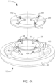
- a metal retainer in the example form of a mild steel retainer ring 209 (best seen in FIG. 4A ) is fastened to the tubular connector 204 on the interior side of the roof wall 109, being oriented substantially parallel to the roof wall 109. In this manner, part of the roof wall 109 is sandwiched between the retainer ring 209 and the button 112, thus retaining the button assembly 111 on the roof wall 109 with limited z-dimensional travel.
- the retainer ring 209 is attached to the tubular connector 204 by a solder connection consisting in this example embodiment of four circumferentially spaced solder joints 219.
- the retention ring 209 in this example embodiment has a plurality of connection cavities in the example form of four regularly circumferentially spaced mortise holes 303 extending transversely through the sheet metal retainer ring 209.
- the operatively lower end of the barrel connector 204 i.e., the upper end in the orientation of FIG. 4A ) defines four tenons 306 that are complementary to and correspond in spatial arrangement to the mortise holes 303.
- Inner surfaces 412 of the mortise holes 303 are provided with a nickel coating, thereby forming respective solder-promoting surfaces.
- the tenons 306 are likewise nickel-coated, providing solder-promoting surfaces on the tenons 306.
- the solder surfaces 408 and 412 are hatched in FIG. 4A .
- the coated surfaces 408, 412 define target zones for the respective solder joints that are to be formed in overlapping regions of the retainer ring 209 and the connector 204, when the tenons 306 are received in the complementary mortise holes 303.
- FIG. 3 therein is shown the button assembly 111 mounted on the housing wall 109 and being disposed in the default condition, in which the retainer ring 209 bears against the inner surface 121 of the roof wall 109.
- the tenons 306 are a loose fit in the corresponding mortise holes 303, with solder material of the respective solder joints 219 attaching to the parallel solder-promoting interface surfaces 408, 412 of the connector 204 and the retainer ring 209 respectively.
- the solder joints 219 are thus in their dimensional extent (also referred to herein as the height of the solder joints 219) restricted substantially to the thickness dimension of the sheet metal retaining ring 209.
- the thickness of the retainer ring 209 is about 0.2 mm, so that the low-profile soldered connection of the example embodiment similarly has a z-dimensional height ( h ) of about 0.2 mm.
- FIG. 4A shows the button assembly 111 in pre-assembled condition and in inverted orientation relative to its operative orientation illustrated in FIGS. 1-3 .
- the solder-promoting surfaces 408, 412 are provided on the barrel connector 204 and the retainer ring 209 by applying the targeted nickel layer or coating previously described.
- the nickel layers are deposited by brush application, but in other embodiments the solder-promoting surfaces 408, 412 can be formed in any suitable manner, such as dipping or electro-plating.
- the inverted orientation of the FIG. 4A is the orientation in which the retainer ring 209 is in this example embodiment soldered to the tubular connector 204, thus utilizing gravity to promote filling of available spaces between the parallel interface surfaces of the tenons 306 and the mortise holes 303, and thereby promoting proper solder attachment to the nickel-coated solder surfaces 408, 412.
- a hollow plastic cylindrical skirt portion 402 that projects from a head 403 of the button 112 and within which the barrel connector 204 is co-axially located has a circumferentially spaced series of recesses 404 in register with and located immediately below the respective tenons 306 of the connector 204. These recesses 404 provide evacuation space for draining of excess solder from the mortise holes 303 during assembly.
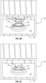
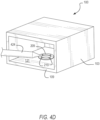
- a first step of assembly ( FIG. 4B ) the housing 103 is placed on a substantially horizontal support surface in an inverted position, with the button 112 located on the housing 103 such that the cylindrical button skirt 403 is coaxial with and extends through the button opening 115.
- the distal end of the barrel connector 204 is substantially flush with the inner surface 121 of the roof wall 109.
- the retainer ring 209 is placed flat on the inner surface 121 of the wall 109, the connector tenons 306 being received in the complementary mating mortise holes 303 with sufficient clearance between the closely spaced, parallel solder-promoting surfaces 408, 412 to receive solder material therein.
- a hand solder iron 424 and solder wire accesses the mortise holes 303 via an open mouth of the housing 103, depositing molten solder material in the respective mortise holes 303.
- the solder material flows under gravity into the clearance space between the walls of the mortise holes 303 and the respective tenons 306, and there solidifies, thus creating a permanent connection between the retainer ring 209 and the connector 204.
- Tin-Silver-Copper solder is used, but any suitable solder material may be used in other embodiments.
- the provision of the respective solder-promoting surfaces 408, 412 promotes creation of the solder joints 219 at the target interface surfaces defined by the respective solder-promoting surfaces 408, 412. This is due in part to the relatively poor solderability of typical steel sheet metal, which inhibits adherence of the solder material to either the connector 204 or the retainer ring 209 outside of the solder-promoting surfaces 408, 412.
- FIG. 5 shows a three-dimensional cross-sectional view of two of the solder joints 219 after the described assembly operation.
- each solder joint 219 is shown as comprising solder material not only between the side faces of the tenons 306 and the parallel interface surfaces of the mortise holes 303, but also includes solder material of about equal thickness on the end faces of the tenons 306.
- solder material in the solder joints 219 is limited to the z-dimensional overlap between the tenons 306 and the thickness of the retainer ring 209.
- the electronic components 213 ( FIG. 2A ) are inserted in the housing 103 and are operationally coupled to the button assembly 111 to allow user control of one or more functionalities of the electronics 213 by operation of the button 112.
- the final housing assembly 100 is incorporated in an end product device, in this example embodiment being an eyewear device in the example form of a pair of smart glasses 600 illustrated schematically in FIG. 6 .
- FIG. 6 shows a front perspective view of an eyewear device in the form of a pair of smart glasses 600 that includes a housing 100 including the low-profile soldered retention mechanism as described with reference to the example embodiment of FIGS. 1-5 .
- the glasses 600 include a body comprising a front piece or frame 606 and a pair of temples 609 connected to the frame 606 for supporting the frame 606 in position on a user's face when the glasses 600 are worn.
- the frame 606 can be made from any suitable material such as plastics or metal, including any suitable shape memory alloy.
- the glasses 600 have a pair of optical elements in the form of a pair of lenses 612 held by corresponding optical element holders in the form of a pair of rims 615 forming part of the frame 606.
- the rims 615 are connected by a bridge 618.
- one or both of the optical elements can be a display (e.g., to provide a virtual reality display), a display assembly, or a lens and display combination (e.g., to provide augmented reality functionalities).
- the frame 606 includes a pair of end pieces 621 defining lateral end portions of the frame 606.
- the housing assembly 100 with its internal electronics 213 is integrated in one of the lateral end pieces 621.
- each end piece 621 includes a housing assembly 100 as described.
- the button 112 of the housing assembly 100 projects through a complementary opening in the end piece 621 to be accessible for user operation.
- the frame 606 is formed of a single piece of material, so as to have a unitary or monolithic construction. In some embodiments, the whole of the body (including both the frame 606 and the temples 609) can be of the unitary or monolithic construction.
- the temples 609 are coupled to the respective end pieces 621.
- the temples 609 are coupled to the frame 606 by respective hinges so as to be hingedly movable between a wearable mode (as shown in FIG. 6 ) and a collapsed mode in which the temples 609 are pivoted towards the frame 606 to lie substantially flat against it.
- Each of the temples 609 includes a front portion that is coupled to the frame 606 and a suitable rear portion for coupling to the ear of the user.
- the glasses 600 has onboard electronics 624 including a computing device, such as a computer, which can in different embodiments be of any suitable type so as to be carried by the eyewear device body.
- various components comprising the onboard electronics 624 are at least partially housed in one or both of the temples 609.
- various components of the onboard electronics 624 are in this example embodiment housed in the housing 100 within the lateral end piece 621 of the frame 606.
- the onboard electronics 624 includes one or more processors with memory, wireless communication circuitry, and a power source (this example embodiment being a rechargeable battery, e.g. a lithium-ion battery).
- the onboard electronics 624 comprises low-power, high-speed circuitry, and, in some embodiments, a display processor.
- Various embodiments may include these elements in different configurations or integrated together in different ways.
- the onboard electronics 624 includes a rechargeable battery.
- the battery is disposed in one of the temples 609. In this example embodiment, however, the battery is housed in one of the end pieces 621, being electrically coupled to the remainder of the onboard electronics 624.
- the glasses 600 is camera-enabled, in this example comprising a camera 630 mounted in one of the end pieces 621 and facing forwards so as to be aligned more or less with the direction of view of a wearer of the glasses 600.
- the camera 630 is configured to capture digital as well as digital video content. Operation of the camera 630 is controlled by a camera controller provided by the onboard electronics 624, image data representative of images or video captured by the camera 630 being temporarily stored on a memory forming part of the onboard electronics 624.
- the glasses 600 can have a pair of cameras 630, e.g. housed by the respective end pieces 621.
- the glasses 600 further include one or more input and output devices permitting communication with and control of the camera 630.
- the glasses 600 include one or more input mechanisms for enabling user control of one or more functions of the glasses 600.
- the input mechanism comprises the button 112.
- a photo capture command can be issued by a single, relatively short button press (e.g., shorter than a second), while a video capture command can be issued by a press-and-hold action.
- the disclosed detection mechanisms uses solder joints 219 as a mechanical joint.
- the low-height bond provided by the solder joints 219 allows the system to substantially maximize space available for other components.
- the use of the disclosed low-profile (in some cases being substantially zero-height) solder bonding in spatially restricted or difficult to access systems allows greater mechanical freedom, better packaging, and improved miniaturization of consumer products.
- use of the disclosed techniques enables a metal-to-metal bond where screw access is impossible, and where providing larger heatstake or ultrasonic welding fixtures are not feasible or practical.
- the low-profile soldered connection for retaining a mounted component on a support structure is in this example embodiment described with reference to a housing for electronics to be incorporated in the example eyewear device 600, the mounting and retention techniques described herein can be implemented in a variety of different applications.
- the disclosed mechanism is particularly useful in applications where z-dimensional space is at a premium, with minimal additional space restriction being provided by the low profile soldered joint.
- an assembly comprising:
- the retainer is of sheet metal construction oriented such that a thickness dimension of the retainer is transverse to the frame wall at the mounted component, e.g. comprising a sheet steel ring lying flat against the frame wall.
- the retainer has one or more connection cavities or openings in which part of the connector is received tenon/mortise-fashion, the solder joint being located at least in part in the one or more cavities.
- the solder joint in such embodiments has a height dimension that is oriented transversely to the frame wall at the mounted component, with the height dimension coinciding substantially with an overlap between the retainer and the connector, so that the height dimension of the solder joint is substantially equal to or smaller than the thickness dimension of the retainer.
- the height or z-dimensional thickness of the joint between the retainer and the connector is defined by the thickness of the sheet metal retainer, thus being small relative to the size of the mounted component, the connector, and the frame wall.
- the connector projects through the retainer substantially no further than a major outer face of the retainer on the reverse side.
- At least one of the retainer and the connector includes a solder-promoting surface that coincides with an overlap between the connector and the retainer, the solder joint being of a different metal material than both the connector and the retainer, and the solder joint attaching to the solder-promoting surface.
- both the connector and the retainer have respective solder-promoting surfaces, the solder joint attaching to the solder-promoting surfaces of both the retainer and the connector. Provision of the solder-promoting surfaces effectively allows for targeting the specific location of the solder joints.
- the solder-promoting surfaces on the connector and the retainer respectively are in some embodiments localized metal coatings, each localized coating for example comprising a nickel coating.
- the term "or" may be construed in either an inclusive or exclusive sense. Moreover, plural instances may be provided for resources, operations, or structures described herein as a single instance. Additionally, boundaries between various resources, operations, modules, engines, and data stores are somewhat arbitrary, and particular operations are illustrated in a context of specific illustrative configurations. Other allocations of functionality are envisioned and may fall within a scope of various embodiments of the present disclosure. In general, structures and functionality presented as separate resources in the example configurations may be implemented as a combined structure or resource. Similarly, structures and functionality presented as a single resource may be implemented as separate resources. These and other variations, modifications, additions, and improvements fall within a scope of embodiments of the present disclosure as represented by the appended claims. The specification and drawings are, accordingly, to be regarded in an illustrative rather than a restrictive sense.
Landscapes
- Physics & Mathematics (AREA)
- Engineering & Computer Science (AREA)
- Health & Medical Sciences (AREA)
- Mechanical Engineering (AREA)
- Acoustics & Sound (AREA)
- General Health & Medical Sciences (AREA)
- Otolaryngology (AREA)
- General Physics & Mathematics (AREA)
- Ophthalmology & Optometry (AREA)
- Optics & Photonics (AREA)
- Chemical & Material Sciences (AREA)
- Materials Engineering (AREA)
- Manufacturing & Machinery (AREA)
- Casings For Electric Apparatus (AREA)
- Telephone Set Structure (AREA)
- Coupling Device And Connection With Printed Circuit (AREA)
Applications Claiming Priority (3)
| Application Number | Priority Date | Filing Date | Title |
|---|---|---|---|
| US15/782,526 US10300545B2 (en) | 2017-10-12 | 2017-10-12 | Low-profile mechanical retention |
| EP18799911.5A EP3695272B1 (de) | 2017-10-12 | 2018-10-10 | Flache mechanische halterung |
| PCT/US2018/055268 WO2019075103A1 (en) | 2017-10-12 | 2018-10-10 | MECHANICAL RETENTION WITH THIN PROFILE |
Related Parent Applications (1)
| Application Number | Title | Priority Date | Filing Date |
|---|---|---|---|
| EP18799911.5A Division EP3695272B1 (de) | 2017-10-12 | 2018-10-10 | Flache mechanische halterung |
Publications (2)
| Publication Number | Publication Date |
|---|---|
| EP4546387A2 true EP4546387A2 (de) | 2025-04-30 |
| EP4546387A3 EP4546387A3 (de) | 2025-07-09 |
Family
ID=64184184
Family Applications (2)
| Application Number | Title | Priority Date | Filing Date |
|---|---|---|---|
| EP18799911.5A Active EP3695272B1 (de) | 2017-10-12 | 2018-10-10 | Flache mechanische halterung |
| EP25163978.7A Pending EP4546387A3 (de) | 2017-10-12 | 2018-10-10 | Mechanische halterung mit niedrigem profil |
Family Applications Before (1)
| Application Number | Title | Priority Date | Filing Date |
|---|---|---|---|
| EP18799911.5A Active EP3695272B1 (de) | 2017-10-12 | 2018-10-10 | Flache mechanische halterung |
Country Status (5)
| Country | Link |
|---|---|
| US (3) | US10300545B2 (de) |
| EP (2) | EP3695272B1 (de) |
| KR (2) | KR102336354B1 (de) |
| CN (2) | CN111194428B (de) |
| WO (1) | WO2019075103A1 (de) |
Families Citing this family (4)
| Publication number | Priority date | Publication date | Assignee | Title |
|---|---|---|---|---|
| US10300545B2 (en) * | 2017-10-12 | 2019-05-28 | Snap Inc. | Low-profile mechanical retention |
| US11822081B2 (en) | 2019-08-29 | 2023-11-21 | Apple Inc. | Optical module for head-mounted device |
| US11885965B1 (en) | 2019-09-23 | 2024-01-30 | Apple Inc. | Head-mounted display and display modules thereof |
| US12277632B2 (en) | 2022-04-26 | 2025-04-15 | Snap Inc. | Augmented reality experiences with dual cameras |
Family Cites Families (34)
| Publication number | Priority date | Publication date | Assignee | Title |
|---|---|---|---|---|
| US631892A (en) * | 1899-05-29 | 1899-08-29 | Louis F Johnson | Electric push-button. |
| US3715708A (en) * | 1970-10-21 | 1973-02-06 | Pace Inc | Electrical connector |
| US3783607A (en) * | 1972-06-12 | 1974-01-08 | Feurer Bros Inc | Pusher for electronic digital watch |
| US4004121A (en) * | 1974-04-04 | 1977-01-18 | Mechanical Enterprises, Inc. | Electrical switch with wire beam spring contact closer |
| US3977907A (en) * | 1975-11-28 | 1976-08-31 | The Gates Rubber Company | Rechargeable battery enclosure |
| FR2443130A1 (fr) * | 1978-11-29 | 1980-06-27 | Serras Paulet Edouard | Clavier de commande de dispositifs electriques ou electroniques |
| JPS57152725U (de) * | 1981-03-20 | 1982-09-25 | ||
| US4394059A (en) * | 1981-08-03 | 1983-07-19 | Amp Incorporated | Connector of a type used with dry cell batteries and manufacturing method |
| US5046971A (en) * | 1988-12-14 | 1991-09-10 | Olin Corporation | Terminal pins for flexible circuits |
| US5664973A (en) * | 1995-01-05 | 1997-09-09 | Motorola, Inc. | Conductive contact |
| TW446616B (en) * | 1999-01-27 | 2001-07-21 | Taisei Plastics Co Ltd | Control panel having sheet-formed pushbutton unit and method of producing the same |
| EP1519452B1 (de) * | 2003-09-23 | 2006-06-21 | Asulab S.A. | Tragbares elektronisches Gerät mit zumindest einem angepassten Betätigungselement zum Übertragen von elektrischen Signalen |
| CN100555752C (zh) * | 2005-09-16 | 2009-10-28 | 鸿富锦精密工业(深圳)有限公司 | 弹性接触装置及使用该弹性接触装置的电子设备 |
| CH698138B1 (de) | 2005-11-09 | 2009-05-29 | Abatek Internat Ag | Integrierter Schalter respektive integrierte Taste. |
| WO2007079633A1 (fr) | 2006-01-11 | 2007-07-19 | Leo Chen | Paire de lunettes equipees d'une camera miniature |
| CN2864735Y (zh) * | 2006-01-11 | 2007-01-31 | 陈笠 | 带摄像装置的眼镜 |
| US20080273166A1 (en) * | 2007-05-04 | 2008-11-06 | William Kokonaski | Electronic eyeglass frame |
| CN200997345Y (zh) * | 2006-11-27 | 2007-12-26 | 梅特勒-托利多仪器(上海)有限公司 | 一种具有卡口结构的按键 |
| US10613355B2 (en) | 2007-05-04 | 2020-04-07 | E-Vision, Llc | Moisture-resistant eye wear |
| CN101312102B (zh) * | 2007-05-25 | 2012-08-22 | 深圳富泰宏精密工业有限公司 | 键盘组件及装设有该键盘组件的便携式电子装置 |
| CN101388297B (zh) * | 2007-09-11 | 2010-09-29 | 徐孝海 | 一种薄膜电路微动开关 |
| CN101604587B (zh) * | 2008-06-13 | 2012-09-26 | 鸿富锦精密工业(深圳)有限公司 | 按键结构 |
| CN201262912Y (zh) * | 2008-07-29 | 2009-06-24 | 达方电子股份有限公司 | 焊接结构以及具有该焊接结构的键盘 |
| US8964352B2 (en) | 2010-04-19 | 2015-02-24 | Apple Inc. | Mounting structures for components in electronic devices |
| US8279588B2 (en) * | 2010-08-19 | 2012-10-02 | Apple Inc. | Self capturing and keyed mobile device button |
| CN102129944B (zh) * | 2011-04-25 | 2014-01-08 | 上海科特高分子材料有限公司 | 薄型温度保险丝及其制造方法 |
| CN201966099U (zh) * | 2011-05-03 | 2011-09-07 | 余正明 | 一种微型侧键开关 |
| CN202564098U (zh) * | 2012-05-04 | 2012-11-28 | 合肥市宏键精工模具有限责任公司 | 一种带灯防水按键开关 |
| US8651900B1 (en) * | 2012-10-25 | 2014-02-18 | Po-Kai Hsu | Connector terminal |
| CN202996653U (zh) * | 2012-12-26 | 2013-06-12 | 浙江沈海防爆灯具有限公司 | 一种防爆按钮套的连接结构 |
| CN204927136U (zh) * | 2015-09-01 | 2015-12-30 | 江西益昕电子科技有限公司 | 一种导向型硅胶按键 |
| CN105390319B (zh) * | 2015-12-03 | 2017-11-10 | 赛诺威盛科技(北京)有限公司 | 一种按键结构 |
| CN106128827B (zh) * | 2016-07-08 | 2017-11-24 | 广东欧珀移动通信有限公司 | 侧键结构及移动终端 |
| US10300545B2 (en) | 2017-10-12 | 2019-05-28 | Snap Inc. | Low-profile mechanical retention |
-
2017
- 2017-10-12 US US15/782,526 patent/US10300545B2/en active Active
-
2018
- 2018-10-10 CN CN201880065238.9A patent/CN111194428B/zh active Active
- 2018-10-10 WO PCT/US2018/055268 patent/WO2019075103A1/en not_active Ceased
- 2018-10-10 EP EP18799911.5A patent/EP3695272B1/de active Active
- 2018-10-10 KR KR1020207013106A patent/KR102336354B1/ko active Active
- 2018-10-10 CN CN202210238249.0A patent/CN114582651B/zh active Active
- 2018-10-10 EP EP25163978.7A patent/EP4546387A3/de active Pending
- 2018-10-10 KR KR1020217039581A patent/KR102454743B1/ko active Active
-
2019
- 2019-03-05 US US16/293,270 patent/US10543547B2/en active Active
- 2019-12-26 US US16/727,581 patent/US10695852B2/en active Active
Also Published As
| Publication number | Publication date |
|---|---|
| CN114582651A (zh) | 2022-06-03 |
| CN111194428B (zh) | 2022-03-29 |
| CN114582651B (zh) | 2024-12-03 |
| KR102454743B1 (ko) | 2022-10-17 |
| EP3695272B1 (de) | 2025-03-19 |
| EP3695272A1 (de) | 2020-08-19 |
| KR20200062312A (ko) | 2020-06-03 |
| EP4546387A3 (de) | 2025-07-09 |
| WO2019075103A1 (en) | 2019-04-18 |
| US10300545B2 (en) | 2019-05-28 |
| US20190111508A1 (en) | 2019-04-18 |
| US10543547B2 (en) | 2020-01-28 |
| US20200147708A1 (en) | 2020-05-14 |
| KR20210152000A (ko) | 2021-12-14 |
| CN111194428A (zh) | 2020-05-22 |
| US20190193179A1 (en) | 2019-06-27 |
| US10695852B2 (en) | 2020-06-30 |
| KR102336354B1 (ko) | 2021-12-08 |
Similar Documents
| Publication | Publication Date | Title |
|---|---|---|
| US10695852B2 (en) | Low-profile mechanical retention | |
| US12222584B2 (en) | Wearable device with heat transfer pathway | |
| EP3848742B1 (de) | Linsenbewegungsvorrichtung und kameramodul damit | |
| CN109683431A (zh) | 镜头驱动装置、摄影模块与电子装置 | |
| TW201523059A (zh) | 3d立體電路導腳結合簧片之結構 | |
| US20080218882A1 (en) | Lens assembly and imaging device | |
| CN107517287B (zh) | 一种壳体组件、移动终端及其摄像头的安装方法 | |
| CN105527775A (zh) | 含有支持手段的相机模块 | |
| CN106464859B (zh) | 相机模块和包括该相机模块的移动终端 | |
| CN110971794B (zh) | 摄像模组以及电子设备 | |
| JP2014191960A (ja) | コンタクトピン、コンタクト組立体、カメラボディ、および交換レンズ | |
| JP5169010B2 (ja) | カメラシステム、カメラ、被装着物 | |
| US11493786B1 (en) | Eyewear with wearer notification | |
| CN109076151A (zh) | 摄像装置 | |
| JP2013152428A (ja) | 電子機器 | |
| CN110662379B (zh) | 一种终端的外壳 | |
| CN207396941U (zh) | 一种高精度遮光纸贴附装置 | |
| CN206892535U (zh) | 摄像辅助件 | |
| JP2008276078A (ja) | カメラシステム、カメラ、被装着物 | |
| JPS59171462U (ja) | 固体撮像素子の取付け構造 | |
| JP2025536935A (ja) | カメラモジュールおよびこれを含む光学機器 | |
| JP2015087534A (ja) | 外装カバー、及び撮像装置 |
Legal Events
| Date | Code | Title | Description |
|---|---|---|---|
| PUAI | Public reference made under article 153(3) epc to a published international application that has entered the european phase |
Free format text: ORIGINAL CODE: 0009012 |
|
| STAA | Information on the status of an ep patent application or granted ep patent |
Free format text: STATUS: THE APPLICATION HAS BEEN PUBLISHED |
|
| AC | Divisional application: reference to earlier application |
Ref document number: 3695272 Country of ref document: EP Kind code of ref document: P |
|
| AK | Designated contracting states |
Kind code of ref document: A2 Designated state(s): AL AT BE BG CH CY CZ DE DK EE ES FI FR GB GR HR HU IE IS IT LI LT LU LV MC MK MT NL NO PL PT RO RS SE SI SK SM TR |
|
| REG | Reference to a national code |
Ref country code: DE Ref legal event code: R079 Free format text: PREVIOUS MAIN CLASS: H01H0013140000 Ipc: G02C0011000000 Ref country code: DE Ref legal event code: R079 Ref document number: 602018091385 Country of ref document: DE Free format text: PREVIOUS MAIN CLASS: H01H0013140000 Ipc: G02C0011000000 |
|
| PUAL | Search report despatched |
Free format text: ORIGINAL CODE: 0009013 |
|
| AK | Designated contracting states |
Kind code of ref document: A3 Designated state(s): AL AT BE BG CH CY CZ DE DK EE ES FI FR GB GR HR HU IE IS IT LI LT LU LV MC MK MT NL NO PL PT RO RS SE SI SK SM TR |
|
| RIC1 | Information provided on ipc code assigned before grant |
Ipc: H01H 13/14 20060101ALI20250530BHEP Ipc: G02C 11/00 20060101AFI20250530BHEP |
|
| STAA | Information on the status of an ep patent application or granted ep patent |
Free format text: STATUS: REQUEST FOR EXAMINATION WAS MADE |
|
| 17P | Request for examination filed |
Effective date: 20250812 |
|
| GRAP | Despatch of communication of intention to grant a patent |
Free format text: ORIGINAL CODE: EPIDOSNIGR1 |
|
| STAA | Information on the status of an ep patent application or granted ep patent |
Free format text: STATUS: GRANT OF PATENT IS INTENDED |
|
| INTG | Intention to grant announced |
Effective date: 20251216 |
|
| REG | Reference to a national code |
Ref country code: HK Ref legal event code: DE Ref document number: 40127495 Country of ref document: HK |
|
| GRAS | Grant fee paid |
Free format text: ORIGINAL CODE: EPIDOSNIGR3 |
|
| GRAA | (expected) grant |
Free format text: ORIGINAL CODE: 0009210 |
|
| STAA | Information on the status of an ep patent application or granted ep patent |
Free format text: STATUS: THE PATENT HAS BEEN GRANTED |