EP4538720A2 - Mehrteiliger stromnebenschluss mit leitendem kanal für gleichmässigen stromfluss - Google Patents
Mehrteiliger stromnebenschluss mit leitendem kanal für gleichmässigen stromfluss Download PDFInfo
- Publication number
- EP4538720A2 EP4538720A2 EP24222037.4A EP24222037A EP4538720A2 EP 4538720 A2 EP4538720 A2 EP 4538720A2 EP 24222037 A EP24222037 A EP 24222037A EP 4538720 A2 EP4538720 A2 EP 4538720A2
- Authority
- EP
- European Patent Office
- Prior art keywords
- shunt
- terminal
- bus
- conductor
- thermocouple
- Prior art date
- Legal status (The legal status is an assumption and is not a legal conclusion. Google has not performed a legal analysis and makes no representation as to the accuracy of the status listed.)
- Pending
Links
Images



Classifications
-
- G—PHYSICS
- G01—MEASURING; TESTING
- G01R—MEASURING ELECTRIC VARIABLES; MEASURING MAGNETIC VARIABLES
- G01R15/00—Details of measuring arrangements of the types provided for in groups G01R17/00 - G01R29/00, G01R33/00 - G01R33/26 or G01R35/00
- G01R15/14—Adaptations providing voltage or current isolation, e.g. for high-voltage or high-current networks
- G01R15/146—Measuring arrangements for current not covered by other subgroups of G01R15/14, e.g. using current dividers, shunts, or measuring a voltage drop
-
- G—PHYSICS
- G01—MEASURING; TESTING
- G01R—MEASURING ELECTRIC VARIABLES; MEASURING MAGNETIC VARIABLES
- G01R1/00—Details of instruments or arrangements of the types included in groups G01R5/00 - G01R13/00 and G01R31/00
- G01R1/20—Modifications of basic electric elements for use in electric measuring instruments; Structural combinations of such elements with such instruments
- G01R1/203—Resistors used for electric measuring, e.g. decade resistors standards, resistors for comparators, series resistors, shunts
-
- G—PHYSICS
- G01—MEASURING; TESTING
- G01R—MEASURING ELECTRIC VARIABLES; MEASURING MAGNETIC VARIABLES
- G01R19/00—Arrangements for measuring currents or voltages or for indicating presence or sign thereof
- G01R19/0092—Measuring current only
-
- G—PHYSICS
- G01—MEASURING; TESTING
- G01R—MEASURING ELECTRIC VARIABLES; MEASURING MAGNETIC VARIABLES
- G01R22/00—Arrangements for measuring time integral of electric power or current, e.g. electricity meters
- G01R22/06—Arrangements for measuring time integral of electric power or current, e.g. electricity meters by electronic methods
- G01R22/061—Details of electronic electricity meters
Definitions
- the shunt described herein may provide uniform current flow, resulting in an accurate measurement of current through the shunt.
- a protrusion that connects a first terminal to a shunt bus may provide a single connection point for current to uniformly flow from the first terminal to the shunt bus where the shunt element is located. This may result in current flow lines of equipotential being more uniform near the shunt element, in comparison to previous U-shaped shunts that provide non-uniform current flow at the corners and the shunt element. Thus, a more accurate voltage reading for the shunt element may be made and, consequently, a more accurate current measurement.
- the one or more hardware components may determine a temperature of the shunt based on a signal from the reference conductor and a signal from the thermocouple conductor. Further, the one or more hardware components may determine an amount of current passing through the shunt based on the signal from the reference conductor and a signal from the sensing conductor. The one or more hardware components may also use the temperature of the shunt to determine the amount of current. That is, the temperature of the shunt may be used to adjust a current measurement for the shunt, thereby leading to an accurate current measurement for the shunt.
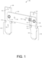
- FIG. 1 illustrates an example shunt 100 having at least one conductive channel that provides a uniform flow of current.
- the shunt 100 includes a shunt bus 102 electrically connected to a first terminal 104 at a first end of the shunt bus 102 and electrically connected to a second terminal 106 at a second end of the shunt bus 102.
- the first and second terminals 104 and 106 may be adapted to electrically connect to a conductive path, such as an electrical socket (e.g., receptacle).
- the first and second terminals 104 and 106 may connect to jaws of a meter socket that is located at a residence.
- the meter socket may form a conductive path at the residence.
- the shunt bus 102, the first terminal 104, and/or the second terminal 106 are elongated members.
- An elongated member may have a length that is longer than a width (in some instances, by more than a particular amount).
- the shunt bus 102 may substantially perpendicular to the first terminal 104 and/or the second terminal 106.
- substantially perpendicular may refer to the components having between a 45-degree angle and a 135-degree angle with respect to each other. In some instances, the components may form a 90-degree angle with respect to each other with plus or minus 5 degrees.
- the shunt bus 102 may not be substantially perpendicular to the first terminal 104 and/or the second terminal 106.
- current may enter through the first terminal 104, pass through the protrusion 108 to the shunt bus 102, pass from the shunt bus 102 to the second terminal 106 through the protrusion 110, and exit through the second terminal 106.
- the first terminal 104, the protrusion 108, the shunt bus 102, the protrusion 110, and the second terminal 106 may form a conductive path from a first jaw of the meter socket to a second jaw of the meter socket, for example.
- the shunt element 112 may be formed of any material.
- the shunt element 112 is composed of a material that is more resistive than a material of the shunt bus 102 (e.g., 40 times more resistive than the copper of the shunt bus 102).
- the shunt element 112 is composed of Manganin ® .
- the shunt element 112 is composed of constantan or nichrome. In other examples, other types of materials are used.
- the protrusions 108 and 110 provide conductive channels for current to flow, as noted above.
- the protrusions 108 and 110 may generally create distance between the respective terminal and protrusion, so that current flows through the protrusion. This distance is illustrated in further detail in FIGS. 2 and 3 .
- the protrusions 108 and 110 may provide connection points from the shunt bus 102 to the terminals 104 and 106, respectively.
- the protrusion 108 may provide a single connection point between the first terminal 104 and the shunt bus 102 (e.g., the protrusion 108 may be the only connection point between those two components).
- FIG. 1 shows the indentation side of the protrusions 108 and 110 (i.e., a front side of the shunt 100). That is, the protrusions 108 and 110 extend from the shunt bus 102 on a back side of the shunt bus 102, as illustrated in FIG. 2 .
- the protrusions 108 and 110 appear as recesses (e.g., dimples), since the front side of the shunt 100 is shown.
- the protrusions 108 and 110 may also be referred to as recesses, raised portions, or more generally conductive channels.
- the protrusions 108 and/or 110 may alternatively, or additionally, be provided on the first and second terminals 104 and/or 106, as stand-alone components, and/or as part of a different component.
- the shunt 100 may also include other components.
- the shunt 100 may include tabs 118 to attach to components of a meter or another device in which the shunt 100 is implemented. Additionally, or alternatively, the tabs 118 may facilitate connection to a socket, such as a meter socket. Further, the tabs 118 may be used for positioning the shunt 100 in the meter itself.
- Sections 120 of the shunt 100 illustrate the portions of the first and second terminals 104 and 106 that are inserted into a socket. The first and second terminals 104 and 106 may be adapted to fit various forms of a socket.
- the components of the shunt 100 may be connected through various manners.
- the components may be brazed, soldered, welded, glued (e.g., with a conductive glue), heated together, connected with an adhesive (e.g., a conductive adhesive), or otherwise joined together.
- a conductive filler e.g., a metal
- the first terminal 104 may be brazed to the shunt bus 102 at the protrusion 108 with a filler metal being applied to the connection point (e.g., the protrusion 108).
- FIGS. 2A, 2B, and 2C illustrate a front view, top view, and side view of the example shunt 100 of FIG. 1 , respectively.
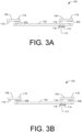
- FIG. 3A illustrates the example shunt 100 with protrusions 302 and 304 that extend off the first and second terminals 104 and 106, respectively.
- FIG. 3A represents an exploded view, with the first and second terminals 104 and 106 being separated from the shunt bus 102.
- the protrusions 302 and 304 form the conductive channels to connect the first and second terminals 104 and 106 to the shunt bus 102, respectively.
- the protrusions 302 and 304 may be the same as the protrusions 108 and 110, except that the protrusions 302 and 304 are part of the first and second terminals 104 and 106, instead of part of the shunt bus 102.
- the protrusions 108 and 110 that extended off the shunt bus 102 have been removed. Although in other examples the protrusions 108 and 110 may remain and attach to the protrusions 302 and 304, respectively.
- the stand-alone components 306 and 308 may be attached to the first and second terminals 104 and 106, respectively, and/or attached to the shunt bus 102 through various manners, such as brazing, soldering, welding, gluing (e.g., with a conductive glue), heating together, using an adhesive (e.g., a conductive adhesive), and so on.
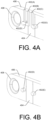
- the half-shear button 402(D) and the pins 402(A) and 402(B) may form a first connection point to the shunt bus 406, while the half-shear button 402(E) and the pin 402(C) may form a second connection point to the shunt bus 406.
- FIGS. 4A and 4B illustrate the connection points 402 positioned on the shunt bus 406, in other examples the connection points 402 may be positioned on the shunt element 404.
- the half-shear buttons 402(D) and 402(E) may be located on the shunt element 404, such as on opposite sides of the shunt element 404.
- FIG. 5A and 5B illustrate example connection points 502 and 504 that represent insulation displacement connection.
- the connection points 502 and 504 may connect to a shunt bus 506 on different sides of a shunt element 508.
- the connection points 502 and 504 may be configured to receive conductors 510 (e.g., wires, leads, traces, etc.) to measure current passing through the shunt element 508 and/or a temperature of the shunt bus 506.
- the conductor 510(A) may comprise a thermocouple conductor
- the conductor 510(B) may comprise a reference conductor
- the conductor 510(C) may comprise a sensing conductor.
- connection points 502 and 504 may be separate components that are insulated from each other through insulation 512.
- the insulation 512 may be non-conductive.
- the connection point 502 may connect to a first side of the shunt element 508, while the connection point 504 separately connects to a second side of the shunt element 508.
- connection points are shown in FIGS. 4 and 5 with specific structural components, in some instances conductors may connect to any location on a shunt bus and/or shunt element.
- conductors may be attached directly to a shunt bus via soldering, brazing, welding, an adhesive, a fastener, gluing, and so on.
- a location where a conductor is attached to the shunt bus comprises a connection point.
- FIGS. 6A-6C shows an example shunt 600 with a connecting element 602.
- the shunt 600 includes a shunt bus 604 connected, at a first end of the shunt bus 604, to a first terminal 606 via a protrusion 608.
- the shunt bus 604 is also connected, at a second end of the shunt bus 604, to a first end of the connecting element 602 via fasteners 610, such as rivets, screws, etc.
- the connecting element 602 is connected, at a second end of the connecting element 602, to a second terminal 612 via fasteners 614, such as rivets, screws, etc.
- the shunt bus 604 is electrically connected to the second terminal 612 via the connecting element 602.
- fasteners 610 and 614 are used in this example, the components may be connected in other manners, such as by soldering, welding, brazing, using an adhesive, gluing, etc.
- the connecting element 602 comprises a switch configured to open or close a conductive path of the shunt 600. That is, the switch may open or close a conductive path between the shunt bus 604 and the second terminal 612.
- a switch may be implemented as that described in U.S. Patent Number 8,395,464 , which is incorporated herein by reference.
- FIG. 6 shows the shunt 600 in a form in which the shunt 600 may generally be implemented (e.g., in a closed form where current can pass through the shunt 600).
- other types of connecting elements may be used instead of the switch.
- FIGS. 6A-6C illustrates that the shunt bus 604 being connected to the first terminal 606 in an offset manner.
- the shunt bus 604 is connected to the first terminal 606 at a side of the first terminal 606 (e.g., left side) that is farthest from the second terminal 612. Such side of the first terminal 606 is represented in FIG. 6B to the left of a center line 616.
- the shunt bus 604 is connected to a substantially planar surface of the first terminal 606.
- the shunt bus 604 includes a shunt element 618 that is offset to one side of the shunt 600 (e.g., to the left).
- the shunt element 618 is above a side of the first terminal 606 that is closest to the second terminal 612 (e.g., a side of the first terminal 606 to a right of the center line 616).
- the connecting element 602 may be positioned between the first terminal 606 and the second terminal 612.
- the shunt 600 is illustrated as being offset in FIGS. 6A-6C to the left, in other examples the shunt bus 604 and/or the shunt element 618 may be offset to the right. In such examples, the shunt bus 604 and the connecting element 602 may be swapped so that the shunt bus 604 connects directly to the second terminal 612 and the connecting element 602 connects directly to the first terminal 606.
- the shunt bus 704 includes a shunt element 712 positioned a distance 714 from the protrusion 702(A).
- the distance 714 may include a predetermined distance that is determined from analyzing current flow through the shunt 700, such as a distance that avoids non-uniform current flow through the shunt element 712.
- the shunt element 712 may be disposed within a predetermined proximity to the protrusion 702(A). In this example, current generally flows in through the first terminal 708 and out the second terminal 710.
- FIG. 8 illustrates an example thermocouple system 800 (e.g., thermocouple device).
- the thermocouple system 800 is described in the context of implementing the shunt 100 of FIG. 1 . However, the thermocouple system 800 may be implemented with other shunts.
- the thermocouple system 800 may include one or more hardware components 802 electrically connected to the shunt 100 via conductors 804.
- the one or more hardware components 802 may be configured to receive signals from the shunt 100 via the conductors 804.
- the one or more hardware components 802 may include a connector 806 to interface the conductors 804 to the one or more hardware components 802.
- the one or more hardware components 802 also include an Analog-to-Digital Converter (ADC) 808 that converts the signals of the conductors 804 from analog signals into digital signals.
- ADC Analog-to-Digital Converter
- the digital and/or analog signals may be stored in memory 810 and/or sent to one or more processors 812.
- the conductors 804 may include a sensing conductor 804(A) electrically connected to the connection point 116, a reference conductor 804(B) (or 804(C)) electrically connected to the connection point 114, and a thermocouple conductor 804(C) (or 804(B)) electrically connected to the connection point 114.
- the thermocouple conductor 804(C) may be composed of a different material (e.g., conductive material) than the reference conductor 804(B).
- the thermocouple conductor 804(C) may be composed of constantan, while the reference conductor 804(B) may be composed of copper.
- thermocouple conductor 804(C) and the reference conductor 804(B) form a type-T thermocouple.
- other types of conductive materials are used, creating different types of thermocouples, such as a type E thermocouple (chromel-constantan), type J thermocouple (iron-constantan), type M thermocouple, type N thermocouple, type B thermocouple, type R thermocouple, type S thermocouple, tungsten/rhenium-alloy thermocouple, type C thermocouple, type D thermocouple, type G thermocouple, chromel-gold/iron thermocouple, type P thermocouple (noble-metal), platinum/molybdenum-alloy thermocouple, iridium/rhodium alloy thermocouple, and so on.
- a type E thermocouple chromel-constantan
- type J thermocouple iron-constantan
- type M thermocouple type N thermocouple
- type B thermocouple type R thermocouple
- thermocouple conductor 804(C) and the reference conductor 804(B) may be insulated from each other except at the sensing junction (the connection point 114) and another location within the one or more hardware components 802 (e.g., the opposite end).
- the reference conductor 804(B) and the thermocouple conductor 804(C) may create a thermocouple, since the two conductors are attached to the same connection point and/or are composed of different materials.
- the one or more hardware components 802 are implemented in the context of the one or more processors 812 and the memory 810.
- the one or more processors 812 may include a central processing unit (CPU), a graphics processing unit (GPU), a microprocessor, and so on.
- the memory 810 (as well as all other memory described herein) may comprise computer-readable media and may take the form of volatile memory, such as random access memory (RAM) and/or non-volatile memory, such as read only memory (ROM) or flash RAM.
- Computer-readable media includes volatile and non-volatile, removable and non-removable media implemented in any method or technology for storage of information such as computer-readable instructions, data structures, program modules, or other data for execution by one or more processors of a computing device.
- Examples of computer-readable media include, but are not limited to, phase change memory (PRAM), static random-access memory (SRAM), dynamic random-access memory (DRAM), other types of random access memory (RAM), read-only memory (ROM), electrically erasable programmable read-only memory (EEPROM), flash memory or other memory technology, compact disk read-only memory (CD-ROM), digital versatile disks (DVD) or other optical storage, magnetic cassettes, magnetic tape, magnetic disk storage or other magnetic storage devices, or any other non-transmission medium that can be used to store information for access by a computing device.
- computer-readable media does not include communication media, such as modulated data signals and carrier waves.
- the one or more hardware components 802 are implemented with a Printed Wiring Board (PWB) or Printed Circuit Board (PCB). In other examples, the one or more hardware components 802 may be implemented with other electric circuits and/or components.
- PWB Printed Wiring Board
- PCB Printed Circuit Board
- the one or more hardware components may be communicatively coupled to the conductors 804 to receive signals from the conductors 804.
- the one or more hardware components 802 may use the signals to facilitate various functionality.
- the memory 810 includes a thermocouple measurement component 814, a shunt measurement component 816, and an alert component 818 to facilitate such functionality.
- the thermocouple measurement component 814, the shunt measurement component 816, and the alert component 818 are implemented as software modules that are executable by the one or more processors 812 that are communicatively coupled to the memory 810.
- the one or more processors 812 may execute the components 814-818 to perform the described operations.
- module is intended to represent example divisions of software for purposes of discussion, and is not intended to represent any type of requirement or required method, manner or necessary organization. Accordingly, while various "modules” are discussed, their functionality and/or similar functionality could be arranged differently (e.g., combined into a fewer number of modules, broken into a larger number of modules, etc.).
- the thermocouple measurement component 814 may be configured to measure a temperature of the shunt 100. As noted above, in many instances a calculation of current through the shunt 100 may be affected by the temperature of the shunt 100 (e.g., due to temperature changes affecting the resistance of the shunt 100). The temperature of the shunt 100 may be affected by meter load (e.g., joule heating), ambient temperature (e.g., environment conditions, such as solar heating), and so on. Thus, the temperature of the shunt 100 may be measured to compensate for inaccuracies of the current measurement facilitated by the shunt measurement component 816.
- meter load e.g., joule heating
- ambient temperature e.g., environment conditions, such as solar heating
- the thermocouple measurement component 814 may retrieve a signal of the reference conductor 804(B) and a signal of the thermocouple conductor 804(C).
- the signals may be retrieved from the memory 810 and/or directly from the shunt 100.
- Each of the signals may comprise a voltage signal, such as a Direct Current (DC) voltage signal or an Alternating Current (AC) voltage signal.
- the thermocouple measurement component 814 may compare the signal from the reference conductor 804(B) to the signal from the thermocouple conductor 804(C) to determine a difference in voltage between the two conductors.
- the thermocouple measurement component 814 may also determine a temperature at the one or more hardware components 802, such as by using a thermometer or another device located at the one or more hardware components 802. This temperature may represent the temperature of the thermocouple at the other end of the thermocouple (e.g., the end opposite the connection point 114). Then, based on the difference in voltage between the reference conductor 804(B) and the thermocouple conductor 804(C) and the temperature at the one or more hardware components 802, the thermocouple measurement component 814 may use a formula to determine the temperature of the shunt 100. The formula may have been formed when calibrating the thermocouple.
- the formula may account for the properties of the reference conductor 804(B) and the thermocouple conductor 804(C), such as the material composition of the conductors, the length/width of conductors, etc.
- the temperature of the shunt 100 represents the temperature at the connection point 114.
- the thermocouple measurement component 814 may generate temperature data indicating the temperature of the shunt 100 and store the temperature data in the memory 810 and/or provide the temperature data to the shunt measurement component 816 and/or the alert component 818.
- the shunt measurement component 816 may be configured to measure an amount of current passing through the shunt 100.
- the shunt measurement component 814 may retrieve a signal of the reference conductor 804(B) and a signal of the sensing conductor 804(A).
- the signals may be retrieved from the memory 810 and/or directly from the shunt 100.
- Each of the signals may comprise a voltage signal, such as a DC voltage signal or an AC voltage signal.
- the shunt measurement component 814 may compare the signal of the reference conductor 804(B) to the signal of the sensing conductor 804(A) to determine a voltage drop across the shunt element 112 (e.g., a voltage difference between the two conductors).
- the shunt measurement component 814 may determine the amount of current passing through the shunt element 112 based on Ohm's law.
- the shunt measurement component 816 may generate current data indicating the amount of current passing through the shunt element 112, store the current data in the memory 810, and/or provide the current data to other components.
- the shunt measurement component 816 may account for a temperature at the shunt 100.
- the shunt measurement component 816 may compensate for a change in resistance of the shunt 100 due to a temperature of the shunt 100.
- the shunt measurement component 816 may reference a temperature curve or other criteria that specifies a relationship between temperature and current/resistance.
- the shunt measurement component 816 may use the temperature curve or other criteria to adjust the current data that is based on the voltage drop across the shunt element 112 (e.g., the voltage difference between the signal from the reference conductor 804(B) and the signal from the sensing conductor 804(A)).
- the alert component 818 may send an alert indicating that the temperature of the conductive path is greater than the threshold.
- the alert may be sent to a service provider computing device associated with a utility (e.g., a central office for the utility), a computing device associated with a technician (e.g., performing maintenance on the meter), a computing device associated with a customer employing the meter, etc.
- a party that receives the alert may disconnect the shunt 100, open a circuit path through the shunt 100 (e.g., flip a switch to stop current flow), and/or perform other actions.
- the alert may be sent while a party is located at the shunt 100, such as while a technician is performing maintenance on a meter (e.g., changing out the meter).
- the alert component 818 may send an instruction or otherwise cause an action to be automatically performed. For example, if the temperature of the conductive path is greater than a threshold, the alert component 818 may automatically interrupt (e.g., break) the conductive path through the shunt 100 (e.g., cause the switch to open the circuit).
- FIG. 8 illustrates the one or more hardware components 802 being implemented in the context of the one or more processors 812 and the memory 810
- the one or more hardware components 802 may be implemented as other components.
- the one or more hardware components 802 may be implemented as one or more Field-programmable Gate Arrays (FPGAs), Application-specific Integrated Circuits (ASICs), Application-specific Standard Products (ASSPs), System-on-a-chip systems (SOCs), Complex Programmable Logic Devices (CPLDs), etc.
- FPGAs Field-programmable Gate Arrays
- ASICs Application-specific Integrated Circuits
- ASSPs Application-specific Standard Products
- SOCs System-on-a-chip systems
- CPLDs Complex Programmable Logic Devices
- thermocouple measurement component 814 the shunt measurement component 816, and/or the alert component 818 on the one or more processors 812, may be implemented in whole or in part by FPGAs, ASICs, ASSPs, SOCs, CPLDs, etc.
- the one or more hardware components 802 may additionally, or alternatively, include a network interface and a radio (not illustrated in FIG. 8 ).
- the network interface may communicate via a wired or wireless network.
- the alert component 818 may send alerts regarding temperature via the network interface and/or the radio.
- the radio may comprise an RF transceiver configured to transmit and/or receive RF signals via one or more of a plurality of channels/frequencies.
- the radio may be configured to communicate using a plurality of different modulation techniques, data rates, protocols, signal strengths, and/or power levels.
- the radio includes an antenna coupled to an RF front end and a baseband processor.
- the RF front end may provide transmitting and/or receiving functions.
- the RF front end may include high-frequency analog and/or hardware components that provide functionality, such as tuning and/or attenuating signals provided by the antenna.
- the RF front end may provide a signal to the baseband processor.
- the baseband processor may be configured as a software (SW) defined radio.
- the baseband processor provides frequency and/or channel selection functionality to the radio.
- the SW defined radio may include mixers, filters, amplifiers, modulators and/or demodulators, detectors, etc., implemented in software executed by a processor, ASIC, or other embedded computing device(s).
- the SW defined radio may utilize processor(s) and software defined and/or stored in the memory 810. Alternatively, or additionally, the radio may be implemented at least in part using analog components.
- the memory 810 may include other types of components.
- the memory 810 may store a metrology component configured to collect consumption data of one or more resources (e.g., electricity, water, natural gas, etc.).
- the consumption data may include, for example, electricity consumption data, water consumption data, and/or natural gas consumption data.
- the consumption data may include data generated at a node where the shunt 100 is implemented (e.g., a meter), another node (e.g., another meter or utility node), or a combination thereof.
- the collected consumption data may be transmitted to a data collector in the case of a star network or, in the case of a mesh network, to one or more other nodes for eventual propagation to a service provider computing device associated with a utility or another destination.
- the meter 900 includes a housing 906 that encloses at least a portion of the shunts 902 and 904, one or more hardware components 908, and conductors 910. As such, the housing may enclose a shunt and a thermocouple device.
- the housing 906 may also include tabs 912 that may be used to assist in connecting the meter 900 to the meter socket.
- the conductors 910 may connect the shunt 902 to the one or more hardware components 908. Although the shunt 904 is not shown in FIG. 9B , the shunt 904 may also be connected to the one or more hardware components 908.
- the conductors 910 may include a reference conductor, sensing conductor, and thermocouple conductor. As illustrated in FIG.
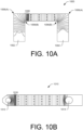
- FIG. 10A illustrates current flow lines for a shunt in related art.
- the shunt 1000 includes a single U-shaped piece that is upside down. Current may enter the shunt at an end 1002 and exit the shunt at an end 1004.
- the vertical and horizontal lines represent current flow lines of equipotential.
- the current flow lines at corners 1006 of the shunt 1000 are non-symmetrical and non-uniform due to the 90-degree bend in the shunt 1000. That is, the current flow lines are wider apart at outside edges 1006(A) in comparison to inner edges 1006(B) of the corners 1006 and/or the current flow lines are curved. This leads to inaccurate current measurements in a measurement region 1008, where the shunt element is located. As the shunt element is positioned closer to a corner, the inaccuracy of the current measurement may increase.
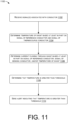
- FIG. 11 illustrates an example process 1100 for employing the techniques described herein.
- the process 1100 is implemented to determine temperature of a shunt, determine current flowing through the shunt, and send an alert regarding temperature of the shunt.
- the process 1100 is described as being performed in the context of FIG. 8 .
- one or more of the individual operations of the process 1100 may be performed by the one or more hardware components 802.
- the process 1100 may be performed in other contexts.
- the process 1100 (as well as each process described herein) are illustrated as a logical flow graph, each operation of which represents a sequence of operations that can be implemented in hardware, software, or a combination thereof.
- the operations represent computer-executable instructions stored on one or more computer-readable storage media that, when executed by one or more processors, perform the recited operations.
- computer-executable instructions include routines, programs, objects, components, data structures, and the like that perform particular functions or implement particular abstract data types.
- the order in which the operations are described is not intended to be construed as a limitation, and any number of the described operations can be combined in any order and/or in parallel to implement the process. Further, any number of the individual operations may be omitted.
- the one or more hardware components 802 may receive signals associated with conductors that are connected to a shunt.
- the conductors may include a reference conductor, a sensing conductor, and a thermocouple conductor.
- the one or more hardware components 802 may determine that a temperature of a conductive path into which the shunt is connected is greater than a threshold. That is, the one or more hardware components 802 may determine that the temperature of the shunt is greater than the threshold.
- the one or more hardware components 802 may send an alert indicating that the temperature is greater than the threshold.
- the alert may be sent to any entity, such as a customer, service provider computing device at a utility, a technician, and so on.
Landscapes
- Physics & Mathematics (AREA)
- General Physics & Mathematics (AREA)
- Measuring Instrument Details And Bridges, And Automatic Balancing Devices (AREA)
- Connection Of Batteries Or Terminals (AREA)
Applications Claiming Priority (3)
| Application Number | Priority Date | Filing Date | Title |
|---|---|---|---|
| US15/386,376 US10788515B2 (en) | 2016-12-21 | 2016-12-21 | Multi-piece current shunt with conductive channel for uniform current flow |
| PCT/US2017/067273 WO2018118894A1 (en) | 2016-12-21 | 2017-12-19 | Multi-piece current shunt with conductive channel for uniform current flow |
| EP17829477.3A EP3559682B1 (de) | 2016-12-21 | 2017-12-19 | Mehrteiliger stromnebenschluss mit leitfähigem kanal für gleichmässigen stromfluss |
Related Parent Applications (2)
| Application Number | Title | Priority Date | Filing Date |
|---|---|---|---|
| EP17829477.3A Division-Into EP3559682B1 (de) | 2016-12-21 | 2017-12-19 | Mehrteiliger stromnebenschluss mit leitfähigem kanal für gleichmässigen stromfluss |
| EP17829477.3A Division EP3559682B1 (de) | 2016-12-21 | 2017-12-19 | Mehrteiliger stromnebenschluss mit leitfähigem kanal für gleichmässigen stromfluss |
Publications (2)
| Publication Number | Publication Date |
|---|---|
| EP4538720A2 true EP4538720A2 (de) | 2025-04-16 |
| EP4538720A3 EP4538720A3 (de) | 2025-06-11 |
Family
ID=60972432
Family Applications (2)
| Application Number | Title | Priority Date | Filing Date |
|---|---|---|---|
| EP24222037.4A Pending EP4538720A3 (de) | 2016-12-21 | 2017-12-19 | Mehrteiliger stromnebenschluss mit leitendem kanal für gleichmässigen stromfluss |
| EP17829477.3A Active EP3559682B1 (de) | 2016-12-21 | 2017-12-19 | Mehrteiliger stromnebenschluss mit leitfähigem kanal für gleichmässigen stromfluss |
Family Applications After (1)
| Application Number | Title | Priority Date | Filing Date |
|---|---|---|---|
| EP17829477.3A Active EP3559682B1 (de) | 2016-12-21 | 2017-12-19 | Mehrteiliger stromnebenschluss mit leitfähigem kanal für gleichmässigen stromfluss |
Country Status (4)
| Country | Link |
|---|---|
| US (2) | US10788515B2 (de) |
| EP (2) | EP4538720A3 (de) |
| CA (1) | CA3047554C (de) |
| WO (1) | WO2018118894A1 (de) |
Families Citing this family (5)
| Publication number | Priority date | Publication date | Assignee | Title |
|---|---|---|---|---|
| US10401392B2 (en) | 2016-12-21 | 2019-09-03 | Itron, Inc. | Shunt thermocouple |
| US10788515B2 (en) | 2016-12-21 | 2020-09-29 | Itron, Inc. | Multi-piece current shunt with conductive channel for uniform current flow |
| DE102017203535A1 (de) * | 2017-03-03 | 2018-09-06 | Continental Automotive Gmbh | Stromsensor mit optimierter Stromdichteverteilung, Verfahren zum Bestimmen eines Laststroms |
| US10856055B2 (en) * | 2019-03-20 | 2020-12-01 | Mellanox Technologies, Ltd. | Apparatuses for improved thermal performance of dynamic network connections |
| US12377732B2 (en) * | 2021-02-19 | 2025-08-05 | Transportation Ip Holdings, Llc | Electrical shunt apparatus and system |
Citations (1)
| Publication number | Priority date | Publication date | Assignee | Title |
|---|---|---|---|---|
| US8395464B2 (en) | 2008-05-30 | 2013-03-12 | Itron, Inc. | Actuator/wedge improvements to embedded meter switch |
Family Cites Families (28)
| Publication number | Priority date | Publication date | Assignee | Title |
|---|---|---|---|---|
| US3059182A (en) * | 1959-08-07 | 1962-10-16 | Westinghouse Electric Corp | Instrument shunts |
| US3447082A (en) | 1965-03-08 | 1969-05-27 | Catharine E Calderhead | Thermocouple milliwattmeter |
| FR2701590B1 (fr) | 1993-02-15 | 1995-04-21 | Sagem | Eléments résistifs de mesure de courant et modules de raccordement et de mesure en comportant application. |
| GB2306676B (en) | 1995-10-31 | 1999-12-08 | Siemens Measurements Ltd | Improvements in or relating to meter switches |
| TR200100572T2 (tr) * | 1998-08-24 | 2001-07-23 | Karin Daume Maschinenteile Gmbh & Co. Kg | Bir koaksiyal kablonun bölüm bölüm izolasyonu açılmış dış iletkeninin eletrik iletken biçimde kontaktlanmasına yarayan alet |
| US6139333A (en) * | 1999-01-19 | 2000-10-31 | The Whitaker Corporation | Connector assembly with shunting switch |
| US6091237A (en) * | 1999-09-14 | 2000-07-18 | Chen; Lee-Fei | Three-phrase clamp-type power meter |
| US7319304B2 (en) * | 2003-07-25 | 2008-01-15 | Midtronics, Inc. | Shunt connection to a PCB of an energy management system employed in an automotive vehicle |
| US7843834B2 (en) | 2006-09-15 | 2010-11-30 | Itron, Inc. | Use of minimal propagation delay path to optimize a mesh network |
| JP4308276B2 (ja) * | 2007-02-05 | 2009-08-05 | レノボ・シンガポール・プライベート・リミテッド | 電子機器の接続構造および機能拡張装置 |
| CN201060231Y (zh) | 2007-06-29 | 2008-05-14 | 吴伟 | 一种高精确度电流检测和温度在线检测装置 |
| ATE535817T1 (de) | 2008-09-29 | 2011-12-15 | Emh Metering Gmbh & Co Kg | Elektronischer elektrizitätszähler |
| DE102009031408A1 (de) * | 2009-07-01 | 2011-01-05 | Isabellenhütte Heusler Gmbh & Co. Kg | Elektronisches Bauelement und entsprechendes Herstellungsverfahren |
| DE102009060577B4 (de) * | 2009-12-23 | 2012-04-26 | Hora-Werk Gmbh | Stromzählerklemme und Verfahren zur Herstellung einer Stromzählerklemme |
| DE102010009835A1 (de) | 2010-03-02 | 2011-09-08 | Isabellenhütte Heusler Gmbh & Co. Kg | Elektronisches Bauelement insbesondere Stromsensor |
| CN102323459B (zh) * | 2011-08-12 | 2013-10-23 | 桐乡市伟达电子有限公司 | 抗交变磁场锰铜分流器 |
| FR2981507B1 (fr) | 2011-10-12 | 2013-12-06 | Commissariat Energie Atomique | Dispositif thermoelectrique securise |
| WO2013093714A1 (en) | 2011-12-23 | 2013-06-27 | Sendyne Corporation | Current shunt |
| WO2014002592A1 (ja) * | 2012-06-29 | 2014-01-03 | 株式会社 村田製作所 | ケーブルの配線基板への固定構造、ケーブル、またはケーブルの製造方法 |
| JP5545334B2 (ja) * | 2012-09-13 | 2014-07-09 | ダイキン工業株式会社 | 電子回路装置 |
| JP2014203544A (ja) * | 2013-04-01 | 2014-10-27 | 富士通コンポーネント株式会社 | 電磁継電器 |
| US9831482B2 (en) * | 2013-09-06 | 2017-11-28 | Johnson Controls Technology Company | Battery module lid system and method |
| US9381367B2 (en) * | 2013-10-25 | 2016-07-05 | Medtronic, Inc. | Medical lead fastener including integrated clamp |
| KR101537169B1 (ko) * | 2013-11-26 | 2015-07-22 | 스마트전자 주식회사 | 전류측정소자 어셈블리 |
| US20150377949A1 (en) | 2014-06-30 | 2015-12-31 | Landis+Gyr, Inc. | Utility Meter with Temperature Sensor |
| JP6637250B2 (ja) | 2015-04-28 | 2020-01-29 | Koa株式会社 | 電流検出装置 |
| US10401392B2 (en) | 2016-12-21 | 2019-09-03 | Itron, Inc. | Shunt thermocouple |
| US10788515B2 (en) | 2016-12-21 | 2020-09-29 | Itron, Inc. | Multi-piece current shunt with conductive channel for uniform current flow |
-
2016
- 2016-12-21 US US15/386,376 patent/US10788515B2/en active Active
-
2017
- 2017-12-19 CA CA3047554A patent/CA3047554C/en active Active
- 2017-12-19 EP EP24222037.4A patent/EP4538720A3/de active Pending
- 2017-12-19 WO PCT/US2017/067273 patent/WO2018118894A1/en not_active Ceased
- 2017-12-19 EP EP17829477.3A patent/EP3559682B1/de active Active
-
2020
- 2020-09-28 US US17/035,476 patent/US11391759B2/en active Active
Patent Citations (1)
| Publication number | Priority date | Publication date | Assignee | Title |
|---|---|---|---|---|
| US8395464B2 (en) | 2008-05-30 | 2013-03-12 | Itron, Inc. | Actuator/wedge improvements to embedded meter switch |
Also Published As
| Publication number | Publication date |
|---|---|
| US11391759B2 (en) | 2022-07-19 |
| EP3559682C0 (de) | 2025-04-23 |
| CA3047554C (en) | 2024-05-28 |
| US20210080488A1 (en) | 2021-03-18 |
| US10788515B2 (en) | 2020-09-29 |
| EP3559682B1 (de) | 2025-04-23 |
| WO2018118894A1 (en) | 2018-06-28 |
| EP4538720A3 (de) | 2025-06-11 |
| EP3559682A1 (de) | 2019-10-30 |
| US20180172736A1 (en) | 2018-06-21 |
| CA3047554A1 (en) | 2018-06-28 |
Similar Documents
| Publication | Publication Date | Title |
|---|---|---|
| US11391759B2 (en) | Multi-piece current shunt with conductive channel for uniform current flow | |
| EP3559686B1 (de) | Shunt-thermoelement | |
| US11293952B2 (en) | Passive current sensor with simplified geometry | |
| US20140292459A1 (en) | Magnetic device having integrated current sensing element and methods of assembling same | |
| WO2023135977A1 (ja) | 電流検出装置およびその製造方法 | |
| JP6603317B2 (ja) | 熱電対の温度補償のための端子盤 | |
| CN104078194B (zh) | 具有一体化电流感测元件的磁性装置及其组装方法 | |
| CN106772186B (zh) | 一种双负载波导量热计的替代效率测量方法和系统 | |
| EP3527995B1 (de) | Shuntwiderstand und messsystem | |
| JP2008082957A (ja) | シャント抵抗器 | |
| US3252091A (en) | Four-terminal junction for electrical measurments and method of making the same | |
| CN108955932B (zh) | 一种波导热敏式测辐射热装置 | |
| JP2020101542A (ja) | バッテリーセンサーのための抵抗アセンブリ、および、バッテリーセンサー | |
| KR20170127092A (ko) | 션트 저항체 | |
| JP5445193B2 (ja) | 抵抗器、抵抗器の実装方法、抵抗器の測定方法 | |
| KR101651262B1 (ko) | 온도 측정 가능한 장치 | |
| CN105509914B (zh) | 一种绝缘且抗电磁场的热电偶 | |
| CN115615570A (zh) | 用于制备食物的食物温度计、系统和方法 | |
| CN223796146U (zh) | 热电偶测温的厚膜式烤盘 | |
| CN219066527U (zh) | 用于检测电流的电阻器和电源装置 | |
| JP2016038232A (ja) | 抵抗値測定用導電材、導電材の抵抗値測定装置、および電流検出装置 | |
| CN108645530B (zh) | 测温系统及利用测温系统测量测温区温度的方法 | |
| CN115327205A (zh) | 电流检测装置 | |
| HU193549B (en) | Heat flux sensor in particular for the measurement of streaming heat throught the walls | |
| JP2019169578A (ja) | 抵抗器およびその製造方法 |
Legal Events
| Date | Code | Title | Description |
|---|---|---|---|
| PUAI | Public reference made under article 153(3) epc to a published international application that has entered the european phase |
Free format text: ORIGINAL CODE: 0009012 |
|
| STAA | Information on the status of an ep patent application or granted ep patent |
Free format text: STATUS: THE APPLICATION HAS BEEN PUBLISHED |
|
| AC | Divisional application: reference to earlier application |
Ref document number: 3559682 Country of ref document: EP Kind code of ref document: P |
|
| AK | Designated contracting states |
Kind code of ref document: A2 Designated state(s): AL AT BE BG CH CY CZ DE DK EE ES FI FR GB GR HR HU IE IS IT LI LT LU LV MC MK MT NL NO PL PT RO RS SE SI SK SM TR |
|
| REG | Reference to a national code |
Ref country code: DE Ref legal event code: R079 Free format text: PREVIOUS MAIN CLASS: G01R0019000000 Ipc: G01R0001200000 |
|
| PUAL | Search report despatched |
Free format text: ORIGINAL CODE: 0009013 |
|
| AK | Designated contracting states |
Kind code of ref document: A3 Designated state(s): AL AT BE BG CH CY CZ DE DK EE ES FI FR GB GR HR HU IE IS IT LI LT LU LV MC MK MT NL NO PL PT RO RS SE SI SK SM TR |
|
| RIC1 | Information provided on ipc code assigned before grant |
Ipc: G01R 22/06 20060101ALN20250507BHEP Ipc: G01R 19/00 20060101ALN20250507BHEP Ipc: G01R 1/20 20060101AFI20250507BHEP |
|
| STAA | Information on the status of an ep patent application or granted ep patent |
Free format text: STATUS: REQUEST FOR EXAMINATION WAS MADE |
|
| 17P | Request for examination filed |
Effective date: 20251120 |
|
| STAA | Information on the status of an ep patent application or granted ep patent |
Free format text: STATUS: EXAMINATION IS IN PROGRESS |