EP4538431A1 - Kristallmaterial, szintillator und strahlungsdetektor - Google Patents
Kristallmaterial, szintillator und strahlungsdetektor Download PDFInfo
- Publication number
- EP4538431A1 EP4538431A1 EP23819775.0A EP23819775A EP4538431A1 EP 4538431 A1 EP4538431 A1 EP 4538431A1 EP 23819775 A EP23819775 A EP 23819775A EP 4538431 A1 EP4538431 A1 EP 4538431A1
- Authority
- EP
- European Patent Office
- Prior art keywords
- crystal
- scintillator
- sample
- crucible
- crystal material
- Prior art date
- Legal status (The legal status is an assumption and is not a legal conclusion. Google has not performed a legal analysis and makes no representation as to the accuracy of the status listed.)
- Pending
Links
Images





Classifications
-
- C—CHEMISTRY; METALLURGY
- C30—CRYSTAL GROWTH
- C30B—SINGLE-CRYSTAL GROWTH; UNIDIRECTIONAL SOLIDIFICATION OF EUTECTIC MATERIAL OR UNIDIRECTIONAL DEMIXING OF EUTECTOID MATERIAL; REFINING BY ZONE-MELTING OF MATERIAL; PRODUCTION OF A HOMOGENEOUS POLYCRYSTALLINE MATERIAL WITH DEFINED STRUCTURE; SINGLE CRYSTALS OR HOMOGENEOUS POLYCRYSTALLINE MATERIAL WITH DEFINED STRUCTURE; AFTER-TREATMENT OF SINGLE CRYSTALS OR A HOMOGENEOUS POLYCRYSTALLINE MATERIAL WITH DEFINED STRUCTURE; APPARATUS THEREFOR
- C30B29/00—Single crystals or homogeneous polycrystalline material with defined structure characterised by the material or by their shape
- C30B29/10—Inorganic compounds or compositions
- C30B29/16—Oxides
- C30B29/22—Complex oxides
- C30B29/30—Niobates; Vanadates; Tantalates
-
- C—CHEMISTRY; METALLURGY
- C30—CRYSTAL GROWTH
- C30B—SINGLE-CRYSTAL GROWTH; UNIDIRECTIONAL SOLIDIFICATION OF EUTECTIC MATERIAL OR UNIDIRECTIONAL DEMIXING OF EUTECTOID MATERIAL; REFINING BY ZONE-MELTING OF MATERIAL; PRODUCTION OF A HOMOGENEOUS POLYCRYSTALLINE MATERIAL WITH DEFINED STRUCTURE; SINGLE CRYSTALS OR HOMOGENEOUS POLYCRYSTALLINE MATERIAL WITH DEFINED STRUCTURE; AFTER-TREATMENT OF SINGLE CRYSTALS OR A HOMOGENEOUS POLYCRYSTALLINE MATERIAL WITH DEFINED STRUCTURE; APPARATUS THEREFOR
- C30B15/00—Single-crystal growth by pulling from a melt, e.g. Czochralski method
- C30B15/34—Edge-defined film-fed crystal-growth using dies or slits
-
- G—PHYSICS
- G01—MEASURING; TESTING
- G01T—MEASUREMENT OF NUCLEAR OR X-RADIATION
- G01T1/00—Measuring X-radiation, gamma radiation, corpuscular radiation, or cosmic radiation
- G01T1/16—Measuring radiation intensity
- G01T1/20—Measuring radiation intensity with scintillation detectors
- G01T1/2018—Scintillation-photodiode combinations
-
- G—PHYSICS
- G01—MEASURING; TESTING
- G01T—MEASUREMENT OF NUCLEAR OR X-RADIATION
- G01T1/00—Measuring X-radiation, gamma radiation, corpuscular radiation, or cosmic radiation
- G01T1/16—Measuring radiation intensity
- G01T1/20—Measuring radiation intensity with scintillation detectors
- G01T1/202—Measuring radiation intensity with scintillation detectors the detector being a crystal
- G01T1/2023—Selection of materials
-
- C—CHEMISTRY; METALLURGY
- C30—CRYSTAL GROWTH
- C30B—SINGLE-CRYSTAL GROWTH; UNIDIRECTIONAL SOLIDIFICATION OF EUTECTIC MATERIAL OR UNIDIRECTIONAL DEMIXING OF EUTECTOID MATERIAL; REFINING BY ZONE-MELTING OF MATERIAL; PRODUCTION OF A HOMOGENEOUS POLYCRYSTALLINE MATERIAL WITH DEFINED STRUCTURE; SINGLE CRYSTALS OR HOMOGENEOUS POLYCRYSTALLINE MATERIAL WITH DEFINED STRUCTURE; AFTER-TREATMENT OF SINGLE CRYSTALS OR A HOMOGENEOUS POLYCRYSTALLINE MATERIAL WITH DEFINED STRUCTURE; APPARATUS THEREFOR
- C30B15/00—Single-crystal growth by pulling from a melt, e.g. Czochralski method
- C30B15/08—Downward pulling
Definitions
- the present invention relates to a crystal material, a scintillator, and a radiation detector.
- a scintillator is used for this type of measurement.
- a scintillator crystal body having a high density has characteristics such as a) having a high radiation stopping power when irradiated with radiation typified by ⁇ -rays, b) having a large effective atomic number, and c) having a large density.
- a scintillator material having a high density is expected to be used as a scintillator material in a Cherenkov detector or a radiation detector for cosmic rays.
- a scintillator material having the above-described characteristics can realize high detection performance due to high radiation stopping power, and effects such as shortening of measurement time and reduction of radiation irradiation time can be expected.
- the material when a material is used as a scintillator material, the material preferably has a higher light emission amount and a higher energy resolution, and for this reason, the scintillator material is preferably used as a transparent single crystal with no impurities.
- a scintillator material having a particularly large density or effective atomic number is used for detecting high-energy radiation, and is mounted on a detector for cosmic ray measurement or a high-energy experiment using an accelerator.
- PbWO 4 single crystal density: 8.28 g/cm 3
- Non-Patent Documents 1 and 2 PbWO 4 single crystal having the highest density among the existing scintillator materials is widely used.
- the present invention has been made to solve the above problems, and an object of the present invention is to provide a lead-free crystal material having a higher density that can be used as a scintillator material.
- a crystal material according to the present invention is an oxide single crystal represented by a chemical formula M 3 (Ta 1-x Nb x )O 3 ⁇ (1), the oxide single crystal having a cubic crystal structure and a density of 8.0 g/cm 3 or more, wherein M in the chemical formula is at least one element selected from rare earth elements, and 0 ⁇ x ⁇ 1 is satisfied.
- a rare earth element serving as a luminescent center is further added.
- a scintillator according to the present invention includes the crystal material.
- a radiation detector includes a scintillator including the crystal material and a photodetector that receives scintillation light from the scintillator.
- the crystal material is an oxide single crystal represented by the chemical formula M 3 (Ta 1-x Nb x )O 3 ⁇ (1), having a cubic crystal structure and a density of 8.0 g/cm 3 or more.
- M in the chemical formula is at least one element selected from rare earth elements, and 0 ⁇ x ⁇ 1 is satisfied.
- the crystal material is a high-melting-point material having a melting point of 2000°C or more.
- M in the chemical formula may be at least one element of Lu, Gd, and La.
- the crystal material according to the above-described embodiment can be used as a scintillator material.
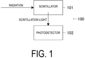
- the radiation detector 100 can be formed of a scintillator 101 configured from the crystal material according to the embodiment and a photodetector 102 that receives scintillation light from the scintillator 101 ( FIG. 1 ).
- the crystal material according to the embodiment has a high radiation stopping performance and a high refractive index.
- the crystal material according to the embodiment can be formed into any thickness depending on a crystal growth method.
- the melting point of Lu 3 TaO 7 is about 2400°C (Reference Document 1).
- the melting point of Lu 3 NbO 7 is about 2030°C (Reference Document 2).
- compositions correspond to congruent compositions. However, it does not mean that the composition should not deviate from the above composition at all, and a deviation in the range of ⁇ 5 mol% with respect to the congruent composition can be allowed. The deviation can be allowed, more preferably, in the range of ⁇ 2 mol%.
- the reason for limiting the range in the vicinity of these compositions is that a single crystal having a solid solution region can be obtained when each composition is in the vicinity of the congruent composition in single crystal growth, and in the other composition range, that is, when a deviation of 5 mol% or more is made, one phase is crystallized first, which becomes a factor for disturbing the single crystal structure.
- the crystal material according to the embodiment emits light through radiation excitation.
- a component ultraviolet earth element serving as a luminescent center
- a lot of additive elements for controlling the emission characteristics can be selected depending on the application and the like, and a single or a plurality of elements can be added.
- the additive element can be selected from rare earth elements such as La, Ce, Pr, Nd, Sm, Eu, Gd, Tb, Dy, Ho, Er, Tm, Yb, and Lu.
- rare earth elements such as La, Ce, Pr, Nd, Sm, Eu, Gd, Tb, Dy, Ho, Er, Tm, Yb, and Lu.
- the above-described elements are added, they can be appropriately selected depending on the requirements of application such as the light emission amount, the light emission wavelength, the fluorescence lifetime, and the energy resolution.
- the amount of each additive element to be added can be appropriately selected depending on the application.
- the rare earth element M and the additive element for controlling the emission characteristics in the chemical formula M 3 (Ta 1-x Nb x )O 3 have different effects, and therefore can be independently selected in accordance with requirements. Selecting the rare earth element M makes it possible to control the band structure of M 3 (Ta 1-x Nb x )O 3 , which is the base material, and to realize efficient energy transfer from the base material to the additive element at the time of radiation excitation.
- the additive element for controlling the light emission characteristics can control the wavelength, fluorescence lifetime, light emission amount, and the like of light emission generated through radiation excitation.
- the crystal material When this type of crystal material is used as a scintillator material, the crystal material preferably has a higher light emission amount and a higher energy resolution, and for this reason, the material is preferably used as a transparent single crystal with no impurities.
- the performance of the scintillator largely depends on the stopping power of radiation.
- the radiation stopping power is a value determined by the density and the effective atomic number, and in general, the radiation stopping power is improved by increasing the density and the effective atomic number.
- a rare earth tantalate represented by the chemical formula RE 3 TaO 7 (RE is a rare earth element) is a material system having a large density and a large effective atomic number, and therefore attracts attention as a scintillator having a high radiation stopping power.
- Many scintillators need to extract light generated through radiation irradiation to the outside, and to efficiently extract light without attenuation, they are used as single crystals that are transparent at the emission wavelength of light.
- RE 3 TaO 7 has a melting point exceeding 2200°C.
- the temperature for crystal growth exceeds the use temperature of platinum or iridium constituting the crucible, and thus the single crystal of RE 3 TaO 7 cannot be grown (crystal growth).
- the crucible In the case of crystal growth in a reducing atmosphere, the crucible may be damaged, the melt of the material to be grown may react with the crucible during crystal growth, the crucible material may be mixed into the crystal, or the raw material may be decomposed in the reducing atmosphere.
- the crystal growth has been used only in very limited systems such as sesquioxide systems and sapphire single crystals.
- the price of rhenium crucible has been raised several times to ten and several times higher than the crucible made of platinum or iridium because of the recent rise in the price of rhenium.
- the rhenium crucible cannot be selected as a method for producing a commercial single crystal.
- This crystal growth method includes a first step of mixing materials constituting a single crystal having a high melting point such as RE 3 TaO 7 , a second step of deoxidizing a heat insulating material in a carbon furnace under a high-temperature inert atmosphere, a third step of melting the material constituting the single crystal having a high melting point filled in a tungsten crucible using the deoxidized heat insulating material, and a fourth step of solidifying the molten material having a high melting point along one direction to form a single crystal.
- a first step of mixing materials constituting a single crystal having a high melting point such as RE 3 TaO 7 a second step of deoxidizing a heat insulating material in a carbon furnace under a high-temperature inert atmosphere
- a third step of melting the material constituting the single crystal having a high melting point filled in a tungsten crucible using the deoxidized heat insulating material and a fourth step of solidifying the molten material having a high melting point along
- Performing crystal growth in this manner can produce a scintillator crystal body having a high melting point of 2100°C or more and a high density.
- this crystal growth method it is possible to grow a crystal without deteriorating the tungsten crucible and while suppressing the reaction between the molten raw material and the crucible by using the deoxidized heat insulating material.
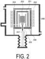
- the micro-pulling-down method is suitable for crystal growth of a crystal material having a high melting point because a solid-liquid interface can be formed immediately below the bottom of a crucible 201 by placing a raw material body 203 in the crucible 201 having a hole at the bottom, heating the crucible 201 by high-frequency induction heating using a high-frequency induction coil 202, and then pulling down the melt of the molten raw material body 203 from the bottom of the crucible 201 using a seed crystal or the like.
- the crucible 201 may be formed of tungsten.
- This apparatus includes the high-frequency induction coil 202 having a length matching the length of the crucible 201, and a heat insulating material 204 for realizing a temperature gradient of 10°C/mm or more at the solid-liquid interface of the raw material body 203 which is a mixture.
- the melt at the bottom of the crucible 201 is pulled down by a seed rod 205 made of tungsten disposed below the crucible 201, whereby solidification is performed in one direction. Not only the seed rod 205 but also a seed crystal can be used.
- the seed rod 205 is fixed to an upper end of a rod 207, and the seed rod 205 can be pulled down by pulling down the rod 207 with a pull-down mechanism (not illustrated).
- the temperature gradient at the solid-liquid interface can be controlled to an optimum value for crystal production by an after heater 206 provided at the lower portion of the crucible 201.
- a production method using an equivalent mechanism is also possible.
- the temperature gradient can be less than 10°C/mm as long as the solid-liquid interface can be made smooth.
- the crucible 201, the high-frequency induction coil 202, the heat insulating material 204, the seed rod 205, and the after heater 206 are disposed in a chamber 208.
- the crystal material can also be produced by crystal pulling as in the Czochralski method.
- the crystal is not pulled down in the downward direction as in the micro-pulling-down method, and thus it is more preferable in that a large crystal body can be produced.
- crystal production in a crucible as in the Bridgman method is also possible. This case is more preferable in that a large crystal body can be produced at a high yield by optimizing the production conditions.
- the crystal material can be produced in the same manner by a floating zone method. This case is more preferable in that it is not necessary to use a crucible, impurities are not mixed from the crucible, and the cost of the crucible is not needed.
- crystal pulling using a die such as the EFG (Edge-defined Film-fed Growth) method, can also be used for producing the crystal material. This case is more preferable in that the shape of the sample to be produced can be controlled.
- the charging composition of the raw material of the crystal body to be produced will be described.
- a deviation of ⁇ 5 mol% or more is allowed. That is, in the case of the micro-pulling-down method, when the raw material is solidified in one direction in the downward direction of the crucible from the state where the entire raw material is melted, the material having the target composition is crystallized first from the beginning of solidification, and the composition of the remaining melt gradually changes.
- the composition of the melt of the raw material body reaches the eutectic point in the latter half or at the end of solidification, and a phase having a composition different from the target composition is phase-separated and precipitated together with the target composition.
- the unnecessary portion thus precipitated may be separated after the crystal body is formed.
- the crystal material according to the embodiment can be used as a radiation detector utilized in environmental measurement, medical equipment, or the like by being combined with a high electron multiplier tube, a multi-pixel photon counter (MPPC), or the like, which is an element performing photoelectric conversion.
- MPPC multi-pixel photon counter
- a scintillator formed of the crystal material according to the embodiment has a high density, the scintillator can be applied to a situation in which detection of radiation with higher energy, measurement in a short time, and use of Cherenkov light with a high refractive index are required.
- the crystal material can be produced at a lower cost than known transparent ceramic materials, and since there is no decrease in transmittance associated with an increase in size, which is a problem with transparent ceramics, the crystal material is preferably applied to situations where a reduction in cost and an increase in size are required. In the above-described applications, adjustment can be made by adding other materials or controlling the amount of addition so as to meet the required characteristics.
- the crucible 201 containing the raw material body was placed above the after heater 206 and heated to a temperature of 2400°C or more by operating the high-frequency induction coil 202.
- the raw material body contained in the crucible 201 was thus completely melted.
- the melt of the raw material body (raw material melt) contained in the crucible 201 appeared on the bottom surface of the die of the crucible 201 through the capillary at the bottom portion, and the melt spread in a wet state.
- the wet-spread raw material melt in this manner was brought into contact with the seed rod 205, and the raw material melt was pulled downward together with the seed rod 205, whereby the raw material melt was unidirectionally solidified while forming a solid-liquid interface immediately below the bottom surface of the crucible 201.
- the rate of pulling down the raw material melt was about from 0.1 to 5 mm/min.
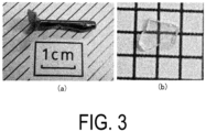
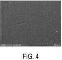
- the polished surface of Sample 1 thus produced was subjected to structural observation and composition analysis in a local region using a scanning electron microscope (SEM) and an energy dispersive X-ray spectroscopy (EDX).
- SEM scanning electron microscope
- EDX energy dispersive X-ray spectroscopy
- Example 2 shows the effect of light emission characteristic control through Nb substitution at the Ta site on Lu 3 TaO 7 produced in Example 1.
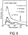
- Sample 1 free of additive elements produced in Example 1 exhibited strong sharp light emission in the vicinity of 290 nm and weak broad light emission in the vicinity of 360 nm in the emission spectrum measurement, as indicated by white circles (additive-free) in FIG. 6 .
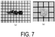
- Sample 2 of a crystal body of Lu 3 (Ta 0.9 Nb 0.1 )O 7 in which the Ta site in Lu 3 TaO 7 was substituted with 10 mol% of Nb was produced by the same production method as in Example 1 ( FIG. 7 ).
- Sample 2 of Example 2 was subjected to phase analysis by XRD measurement in the same manner as described above.
- Sample 2 had a single phase as in Sample 1 free of additive elements, and from composition analysis using EDX, Sample 2 was composed of a single phase containing only La, Ta, Nb, and O.
- Example 3 will be described.
- Sample 3 was produced by further doping 0.5 mol% of Ce at the Lu site of Lu 3 TaO 7 by the same preparation method as described above.
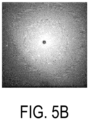
- the crystal body shown in FIG. 8 was able to be obtained, and it was found by XRD measurement, composition analysis by EDX, and Laue image measurement that the crystal body was a single crystal having the same crystal structure as that of the additive-free Lu 3 TaO 7 (Sample 1).
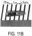
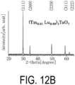
- Example 4 a sample of Lu 3 TaO 7 doped with 1 mol% of Tb or Tm at the Lu site was produced by the same production method as described above. As a result, the crystal bodies shown in FIGS. 11A and 11B were able to be obtained.
- FIG. 11A shows a sample of Lu 3 TaO 7 doped with 1 mol% of Tb at the Lu site
- FIG. 11B shows a sample of Lu 3 TaO 7 doped with 1 mol% of Tm at the Lu site.
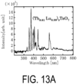
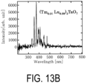
- FIGS. 13A and 13B the results of radioluminescence measurement with X-ray for each of the above-described samples are shown in FIGS. 13A and 13B .
- FIG. 13A in the sample of Tb-doped Lu 3 TaO 7 , an emission peak that was not confirmed in the sample free of additive elements was clearly confirmed in the range of from 500 to 600 nm. From this result, it was found that light emission derived from each additive element was exhibited by changing the additive element.
- the present invention in which a single crystal having a density of M 3 (Ta 1-x Nb x )O 5 of at least one element M selected from rare earth elements of 8.0 g/cm 3 or more is used, can provide a lead-free crystal material having a higher density that can be used as a scintillator material.
Landscapes
- Chemical & Material Sciences (AREA)
- Crystallography & Structural Chemistry (AREA)
- Organic Chemistry (AREA)
- Metallurgy (AREA)
- Materials Engineering (AREA)
- Engineering & Computer Science (AREA)
- High Energy & Nuclear Physics (AREA)
- Molecular Biology (AREA)
- Spectroscopy & Molecular Physics (AREA)
- General Physics & Mathematics (AREA)
- Life Sciences & Earth Sciences (AREA)
- Health & Medical Sciences (AREA)
- Physics & Mathematics (AREA)
- Inorganic Chemistry (AREA)
- Crystals, And After-Treatments Of Crystals (AREA)
Applications Claiming Priority (2)
| Application Number | Priority Date | Filing Date | Title |
|---|---|---|---|
| JP2022092879 | 2022-06-08 | ||
| PCT/JP2023/020646 WO2023238795A1 (ja) | 2022-06-08 | 2023-06-02 | 結晶材料、シンチレータ、および放射線検出器 |
Publications (2)
| Publication Number | Publication Date |
|---|---|
| EP4538431A1 true EP4538431A1 (de) | 2025-04-16 |
| EP4538431A4 EP4538431A4 (de) | 2026-05-20 |
Family
ID=89118401
Family Applications (1)
| Application Number | Title | Priority Date | Filing Date |
|---|---|---|---|
| EP23819775.0A Pending EP4538431A4 (de) | 2022-06-08 | 2023-06-02 | Kristallmaterial, szintillator und strahlungsdetektor |
Country Status (4)
| Country | Link |
|---|---|
| US (1) | US20250341023A1 (de) |
| EP (1) | EP4538431A4 (de) |
| JP (1) | JPWO2023238795A1 (de) |
| WO (1) | WO2023238795A1 (de) |
Family Cites Families (9)
| Publication number | Priority date | Publication date | Assignee | Title |
|---|---|---|---|---|
| EP1816241A4 (de) * | 2004-11-08 | 2010-04-28 | Tohoku Techno Arch Co Ltd | Pr-haltiger einkristall für szintillator, herstellungsverfahren dafür, strahlungsdetektor und inspektionsapparatur |
| JP5288226B2 (ja) * | 2005-09-16 | 2013-09-11 | 日立金属株式会社 | 磁性合金、アモルファス合金薄帯、および磁性部品 |
| WO2012105582A1 (en) * | 2011-01-31 | 2012-08-09 | Canon Kabushiki Kaisha | Composition for optical members and optical member |
| CN104364887B (zh) * | 2012-05-22 | 2017-09-22 | 株式会社东芝 | 等离子体处理装置用部件和等离子体处理装置用部件的制造方法 |
| WO2015037726A1 (ja) * | 2013-09-13 | 2015-03-19 | Tdk株式会社 | シンチレータ結晶材料、単結晶シンチレータ、放射線検出器、撮像装置および非破壊検査装置 |
| US9561969B2 (en) * | 2014-04-18 | 2017-02-07 | University Of Tennessee Research Foundation | Intrinsic complex halide elpasolite scintillators and methods of making and using same |
| WO2016167334A1 (ja) * | 2015-04-16 | 2016-10-20 | 三菱化学株式会社 | 放射線像変換スクリーン、フラットパネルディテクタ、放射線検出装置、及びシンチレータ |
| US10000698B2 (en) * | 2016-03-08 | 2018-06-19 | Lawrence Livermore National Security, Llc | Transparent ceramic garnet scintillator detector for positron emission tomography |
| CN110629287A (zh) * | 2019-10-23 | 2019-12-31 | 安徽工业大学 | 一种铈掺杂钽铌酸镧闪烁晶体材料及其制备方法 |
-
2023
- 2023-06-02 WO PCT/JP2023/020646 patent/WO2023238795A1/ja not_active Ceased
- 2023-06-02 EP EP23819775.0A patent/EP4538431A4/de active Pending
- 2023-06-02 JP JP2024526421A patent/JPWO2023238795A1/ja active Pending
- 2023-06-02 US US18/872,132 patent/US20250341023A1/en active Pending
Also Published As
| Publication number | Publication date |
|---|---|
| EP4538431A4 (de) | 2026-05-20 |
| JPWO2023238795A1 (de) | 2023-12-14 |
| US20250341023A1 (en) | 2025-11-06 |
| WO2023238795A1 (ja) | 2023-12-14 |
Similar Documents
| Publication | Publication Date | Title |
|---|---|---|
| Kamada et al. | Composition engineering in cerium-doped (Lu, Gd) 3 (Ga, Al) 5O12 single-crystal scintillators | |
| US8999281B2 (en) | Scintillator single crystal, heat treatment method for production of scintillator single crystal, and method for production of scintillator single crystal | |
| JP6971327B2 (ja) | 一価イオンが共ドープされたガーネットシンチレータ | |
| EP2640807A1 (de) | Leuchtstoff mit dotiertem seltenerdsilikat | |
| JPWO2006049284A1 (ja) | Prを含むシンチレータ用単結晶及びその製造方法並びに放射線検出器及び検査装置 | |
| US20070292330A1 (en) | Scintillator single crystal and process for its production | |
| US11567223B2 (en) | Scintillation material of rare earth orthosilicate doped with strong electron-affinitive element and its preparation method and application thereof | |
| EP3636805B1 (de) | Herstellungsverfahren für einen yttriumdotierten bariumfluoridkristall | |
| US8778225B2 (en) | Iodide single crystal, production process thereof, and scintillator comprising iodide single crystal | |
| JP2009046598A (ja) | シンチレータ用単結晶材料 | |
| Zhang et al. | Structural and optical properties of GdAlO3: Tb3+ crystal obtained by optical floating zone method | |
| WO2007099772A1 (ja) | シンチレータ用単結晶材料及び製造方法 | |
| US9175420B2 (en) | Suppression of crystal growth instabilities during production of rare-earth oxyorthosilicate crystals | |
| US20250341023A1 (en) | Crystal material, scintillator, and radiation detector | |
| WO2003080903A1 (en) | LUMINOUS MATERIAL FOR SCINTILLATOR COMPRISING SINGLE CRYSTAL OF Yb MIXED CRYSTAL OXIDE | |
| CN112522787A (zh) | 一种硅格位掺杂竞争发光中心的稀土正硅酸盐闪烁材料及其制备方法和应用 | |
| Yiting et al. | Vertical bridgman growth and scintillation properties of doped Bi4Si3O12 crystals | |
| WO2024179025A1 (zh) | 一种铈激活的稀土硅酸盐无机闪烁材料及其制备方法 | |
| CN117186891B (zh) | 一种高品质因子的过渡金属元素掺杂石榴石构型铝酸盐闪烁材料及其制备方法和应用 | |
| US20250102686A1 (en) | Codoped cesium iodide scintillators | |
| JPWO2018110451A1 (ja) | 電離放射線検出用の蛍光体、該蛍光体を含む蛍光体材料、並びに該蛍光体材料を備えた検査装置及び診断装置 | |
| JP4839634B2 (ja) | シンチレータの製造方法及びシンチレータ | |
| CN100388405C (zh) | 掺铈掺铕铝酸镥钇亚微米成像荧光屏及其制备方法 | |
| JP2004137489A (ja) | 放射線検出用フッ化物単結晶材料及び放射線検出器 | |
| CN121975523A (zh) | 高能量分辨石榴石铝酸盐闪烁材料及其制备方法与应用 |
Legal Events
| Date | Code | Title | Description |
|---|---|---|---|
| STAA | Information on the status of an ep patent application or granted ep patent |
Free format text: STATUS: THE INTERNATIONAL PUBLICATION HAS BEEN MADE |
|
| PUAI | Public reference made under article 153(3) epc to a published international application that has entered the european phase |
Free format text: ORIGINAL CODE: 0009012 |
|
| STAA | Information on the status of an ep patent application or granted ep patent |
Free format text: STATUS: REQUEST FOR EXAMINATION WAS MADE |
|
| 17P | Request for examination filed |
Effective date: 20241205 |
|
| AK | Designated contracting states |
Kind code of ref document: A1 Designated state(s): AL AT BE BG CH CY CZ DE DK EE ES FI FR GB GR HR HU IE IS IT LI LT LU LV MC ME MK MT NL NO PL PT RO RS SE SI SK SM TR |
|
| DAV | Request for validation of the european patent (deleted) | ||
| DAX | Request for extension of the european patent (deleted) | ||
| A4 | Supplementary search report drawn up and despatched |
Effective date: 20260420 |
|
| RIC1 | Information provided on ipc code assigned before grant |
Ipc: C30B 29/30 20060101AFI20260414BHEP Ipc: C30B 15/08 20060101ALI20260414BHEP Ipc: C30B 15/34 20060101ALI20260414BHEP |