EP4538075A2 - Kühl- oder warmvorrichtung und fahrzeug - Google Patents
Kühl- oder warmvorrichtung und fahrzeug Download PDFInfo
- Publication number
- EP4538075A2 EP4538075A2 EP25160633.1A EP25160633A EP4538075A2 EP 4538075 A2 EP4538075 A2 EP 4538075A2 EP 25160633 A EP25160633 A EP 25160633A EP 4538075 A2 EP4538075 A2 EP 4538075A2
- Authority
- EP
- European Patent Office
- Prior art keywords
- machine room
- refrigerating
- warming apparatus
- cavity
- heat
- Prior art date
- Legal status (The legal status is an assumption and is not a legal conclusion. Google has not performed a legal analysis and makes no representation as to the accuracy of the status listed.)
- Pending
Links
Images


Classifications
-
- B—PERFORMING OPERATIONS; TRANSPORTING
- B60—VEHICLES IN GENERAL
- B60H—ARRANGEMENTS OF HEATING, COOLING, VENTILATING OR OTHER AIR-TREATING DEVICES SPECIALLY ADAPTED FOR PASSENGER OR GOODS SPACES OF VEHICLES
- B60H3/00—Other air-treating devices
-
- B—PERFORMING OPERATIONS; TRANSPORTING
- B60—VEHICLES IN GENERAL
- B60H—ARRANGEMENTS OF HEATING, COOLING, VENTILATING OR OTHER AIR-TREATING DEVICES SPECIALLY ADAPTED FOR PASSENGER OR GOODS SPACES OF VEHICLES
- B60H1/00—Heating, cooling or ventilating devices
- B60H1/00507—Details, e.g. mounting arrangements, desaeration devices
- B60H1/00514—Details of air conditioning housings
- B60H1/0055—Details of air conditioning housings the housing or parts thereof being integrated in other devices, e.g. dashboard
-
- B—PERFORMING OPERATIONS; TRANSPORTING
- B60—VEHICLES IN GENERAL
- B60H—ARRANGEMENTS OF HEATING, COOLING, VENTILATING OR OTHER AIR-TREATING DEVICES SPECIALLY ADAPTED FOR PASSENGER OR GOODS SPACES OF VEHICLES
- B60H1/00—Heating, cooling or ventilating devices
- B60H1/00507—Details, e.g. mounting arrangements, desaeration devices
- B60H1/00592—Add-on devices, e.g. heat/cooling boxes, compartment dividers, upgrade sets
-
- B—PERFORMING OPERATIONS; TRANSPORTING
- B60—VEHICLES IN GENERAL
- B60R—VEHICLES, VEHICLE FITTINGS, OR VEHICLE PARTS, NOT OTHERWISE PROVIDED FOR
- B60R7/00—Stowing or holding appliances inside vehicle primarily intended for personal property smaller than suit-cases, e.g. travelling articles, or maps
- B60R7/04—Stowing or holding appliances inside vehicle primarily intended for personal property smaller than suit-cases, e.g. travelling articles, or maps in driver or passenger space, e.g. using racks
-
- F—MECHANICAL ENGINEERING; LIGHTING; HEATING; WEAPONS; BLASTING
- F25—REFRIGERATION OR COOLING; COMBINED HEATING AND REFRIGERATION SYSTEMS; HEAT PUMP SYSTEMS; MANUFACTURE OR STORAGE OF ICE; LIQUEFACTION SOLIDIFICATION OF GASES
- F25D—REFRIGERATORS; COLD ROOMS; ICE-BOXES; COOLING OR FREEZING APPARATUS NOT OTHERWISE PROVIDED FOR
- F25D17/00—Arrangements for circulating cooling fluids; Arrangements for circulating gas, e.g. air, within refrigerated spaces
- F25D17/04—Arrangements for circulating cooling fluids; Arrangements for circulating gas, e.g. air, within refrigerated spaces for circulating air, e.g. by convection
- F25D17/06—Arrangements for circulating cooling fluids; Arrangements for circulating gas, e.g. air, within refrigerated spaces for circulating air, e.g. by convection by forced circulation
- F25D17/067—Evaporator fan units
-
- F—MECHANICAL ENGINEERING; LIGHTING; HEATING; WEAPONS; BLASTING
- F25—REFRIGERATION OR COOLING; COMBINED HEATING AND REFRIGERATION SYSTEMS; HEAT PUMP SYSTEMS; MANUFACTURE OR STORAGE OF ICE; LIQUEFACTION SOLIDIFICATION OF GASES
- F25D—REFRIGERATORS; COLD ROOMS; ICE-BOXES; COOLING OR FREEZING APPARATUS NOT OTHERWISE PROVIDED FOR
- F25D27/00—Lighting arrangements
-
- F—MECHANICAL ENGINEERING; LIGHTING; HEATING; WEAPONS; BLASTING
- F25—REFRIGERATION OR COOLING; COMBINED HEATING AND REFRIGERATION SYSTEMS; HEAT PUMP SYSTEMS; MANUFACTURE OR STORAGE OF ICE; LIQUEFACTION SOLIDIFICATION OF GASES
- F25D—REFRIGERATORS; COLD ROOMS; ICE-BOXES; COOLING OR FREEZING APPARATUS NOT OTHERWISE PROVIDED FOR
- F25D29/00—Arrangement or mounting of control or safety devices
- F25D29/003—Arrangement or mounting of control or safety devices for movable devices
-
- F—MECHANICAL ENGINEERING; LIGHTING; HEATING; WEAPONS; BLASTING
- F25—REFRIGERATION OR COOLING; COMBINED HEATING AND REFRIGERATION SYSTEMS; HEAT PUMP SYSTEMS; MANUFACTURE OR STORAGE OF ICE; LIQUEFACTION SOLIDIFICATION OF GASES
- F25D—REFRIGERATORS; COLD ROOMS; ICE-BOXES; COOLING OR FREEZING APPARATUS NOT OTHERWISE PROVIDED FOR
- F25D29/00—Arrangement or mounting of control or safety devices
- F25D29/005—Mounting of control devices
-
- B—PERFORMING OPERATIONS; TRANSPORTING
- B60—VEHICLES IN GENERAL
- B60N—SEATS SPECIALLY ADAPTED FOR VEHICLES; VEHICLE PASSENGER ACCOMMODATION NOT OTHERWISE PROVIDED FOR
- B60N3/00—Arrangements or adaptations of other passenger fittings, not otherwise provided for
- B60N3/10—Arrangements or adaptations of other passenger fittings, not otherwise provided for of receptacles for food or beverages, e.g. refrigerated
- B60N3/104—Arrangements or adaptations of other passenger fittings, not otherwise provided for of receptacles for food or beverages, e.g. refrigerated with refrigerating or warming systems
-
- F—MECHANICAL ENGINEERING; LIGHTING; HEATING; WEAPONS; BLASTING
- F25—REFRIGERATION OR COOLING; COMBINED HEATING AND REFRIGERATION SYSTEMS; HEAT PUMP SYSTEMS; MANUFACTURE OR STORAGE OF ICE; LIQUEFACTION SOLIDIFICATION OF GASES
- F25D—REFRIGERATORS; COLD ROOMS; ICE-BOXES; COOLING OR FREEZING APPARATUS NOT OTHERWISE PROVIDED FOR
- F25D2201/00—Insulation
- F25D2201/10—Insulation with respect to heat
- F25D2201/14—Insulation with respect to heat using subatmospheric pressure
-
- F—MECHANICAL ENGINEERING; LIGHTING; HEATING; WEAPONS; BLASTING
- F25—REFRIGERATION OR COOLING; COMBINED HEATING AND REFRIGERATION SYSTEMS; HEAT PUMP SYSTEMS; MANUFACTURE OR STORAGE OF ICE; LIQUEFACTION SOLIDIFICATION OF GASES
- F25D—REFRIGERATORS; COLD ROOMS; ICE-BOXES; COOLING OR FREEZING APPARATUS NOT OTHERWISE PROVIDED FOR
- F25D23/00—General constructional features
- F25D23/003—General constructional features for cooling refrigerating machinery
-
- F—MECHANICAL ENGINEERING; LIGHTING; HEATING; WEAPONS; BLASTING
- F25—REFRIGERATION OR COOLING; COMBINED HEATING AND REFRIGERATION SYSTEMS; HEAT PUMP SYSTEMS; MANUFACTURE OR STORAGE OF ICE; LIQUEFACTION SOLIDIFICATION OF GASES
- F25D—REFRIGERATORS; COLD ROOMS; ICE-BOXES; COOLING OR FREEZING APPARATUS NOT OTHERWISE PROVIDED FOR
- F25D23/00—General constructional features
- F25D23/006—General constructional features for mounting refrigerating machinery components
-
- F—MECHANICAL ENGINEERING; LIGHTING; HEATING; WEAPONS; BLASTING
- F25—REFRIGERATION OR COOLING; COMBINED HEATING AND REFRIGERATION SYSTEMS; HEAT PUMP SYSTEMS; MANUFACTURE OR STORAGE OF ICE; LIQUEFACTION SOLIDIFICATION OF GASES
- F25D—REFRIGERATORS; COLD ROOMS; ICE-BOXES; COOLING OR FREEZING APPARATUS NOT OTHERWISE PROVIDED FOR
- F25D2323/00—General constructional features not provided for in other groups of this subclass
- F25D2323/002—Details for cooling refrigerating machinery
- F25D2323/0026—Details for cooling refrigerating machinery characterised by the incoming air flow
- F25D2323/00265—Details for cooling refrigerating machinery characterised by the incoming air flow through the front top part
-
- F—MECHANICAL ENGINEERING; LIGHTING; HEATING; WEAPONS; BLASTING
- F25—REFRIGERATION OR COOLING; COMBINED HEATING AND REFRIGERATION SYSTEMS; HEAT PUMP SYSTEMS; MANUFACTURE OR STORAGE OF ICE; LIQUEFACTION SOLIDIFICATION OF GASES
- F25D—REFRIGERATORS; COLD ROOMS; ICE-BOXES; COOLING OR FREEZING APPARATUS NOT OTHERWISE PROVIDED FOR
- F25D2323/00—General constructional features not provided for in other groups of this subclass
- F25D2323/002—Details for cooling refrigerating machinery
- F25D2323/0027—Details for cooling refrigerating machinery characterised by the out-flowing air
- F25D2323/00276—Details for cooling refrigerating machinery characterised by the out-flowing air from the bottom
-
- F—MECHANICAL ENGINEERING; LIGHTING; HEATING; WEAPONS; BLASTING
- F25—REFRIGERATION OR COOLING; COMBINED HEATING AND REFRIGERATION SYSTEMS; HEAT PUMP SYSTEMS; MANUFACTURE OR STORAGE OF ICE; LIQUEFACTION SOLIDIFICATION OF GASES
- F25D—REFRIGERATORS; COLD ROOMS; ICE-BOXES; COOLING OR FREEZING APPARATUS NOT OTHERWISE PROVIDED FOR
- F25D2323/00—General constructional features not provided for in other groups of this subclass
- F25D2323/002—Details for cooling refrigerating machinery
- F25D2323/0027—Details for cooling refrigerating machinery characterised by the out-flowing air
- F25D2323/00277—Details for cooling refrigerating machinery characterised by the out-flowing air from the side
-
- F—MECHANICAL ENGINEERING; LIGHTING; HEATING; WEAPONS; BLASTING
- F25—REFRIGERATION OR COOLING; COMBINED HEATING AND REFRIGERATION SYSTEMS; HEAT PUMP SYSTEMS; MANUFACTURE OR STORAGE OF ICE; LIQUEFACTION SOLIDIFICATION OF GASES
- F25D—REFRIGERATORS; COLD ROOMS; ICE-BOXES; COOLING OR FREEZING APPARATUS NOT OTHERWISE PROVIDED FOR
- F25D2400/00—General features of, or devices for refrigerators, cold rooms, ice-boxes, or for cooling or freezing apparatus not covered by any other subclass
- F25D2400/10—Refrigerator top-coolers
-
- F—MECHANICAL ENGINEERING; LIGHTING; HEATING; WEAPONS; BLASTING
- F25—REFRIGERATION OR COOLING; COMBINED HEATING AND REFRIGERATION SYSTEMS; HEAT PUMP SYSTEMS; MANUFACTURE OR STORAGE OF ICE; LIQUEFACTION SOLIDIFICATION OF GASES
- F25D—REFRIGERATORS; COLD ROOMS; ICE-BOXES; COOLING OR FREEZING APPARATUS NOT OTHERWISE PROVIDED FOR
- F25D2700/00—Means for sensing or measuring; Sensors therefor
- F25D2700/12—Sensors measuring the inside temperature
-
- F—MECHANICAL ENGINEERING; LIGHTING; HEATING; WEAPONS; BLASTING
- F25—REFRIGERATION OR COOLING; COMBINED HEATING AND REFRIGERATION SYSTEMS; HEAT PUMP SYSTEMS; MANUFACTURE OR STORAGE OF ICE; LIQUEFACTION SOLIDIFICATION OF GASES
- F25D—REFRIGERATORS; COLD ROOMS; ICE-BOXES; COOLING OR FREEZING APPARATUS NOT OTHERWISE PROVIDED FOR
- F25D31/00—Other cooling or freezing apparatus
- F25D31/005—Combined cooling and heating devices
Definitions
- a part constituting the refrigeration cycle since a part constituting the refrigeration cycle is large in size, most of the parts are mounted on a trunk, and only a door of a door of the refrigerator is opened to the inside of the vehicle. In this case, there is a limitation that a position for installing the refrigerator for the vehicle is limited. Also, there is a limitation that the trunk is significantly reduced in volume to reduce an amount of cargo that is capable of being loaded in the trunk.
- the vehicle in another embodiment, to obtain a vehicle on which a refrigerating or warming apparatus having a quick temperature adjustment performance is mounted, includes: a console; a suction port and an exhaust port, which are provided in left and right sides of the console; a cavity and a machine room, which are horizontally provided in an inner space of the console; a compressor and a first heat exchange module, which are provided in the machine room; and a second heat exchange module accommodated in the cavity.
- the vehicle may further include a passage guide provided in the refrigerator bottom frame to guide a flow of air discharged to the outside of the machine room to the exhaust port.
- the vehicle may further include a connection passage between an inlet end of the exhaust port and a discharge end of the passage guide.
- the vehicle may further include a blocking wall blocking a space between a bottom of an inner space of the console and the discharge end of the passage guide.
- the passage guide for guiding the discharge-side air of the internal air flow to the direction opposite to the cavity may be provided.
- the hot air may not be applied the cavity to reduce the heat load.
- the width of the air flow decreases ad the external air flow proceeds, the sufficient space for cooling each of the parts provided inside and outside the machine room and dissipating the heat of the parts may be secured.
- the passage guide may be vertically aligned with the compressor to quickly discharge the air and realize the high-integration of the machine room.
- the air flowing through the controller may be introduced into the machine room to satisfy the heat dissipation conditions of the controller.
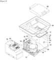
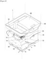
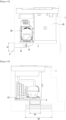
- the vehicle refrigerator 7 includes a refrigerator bottom frame 8 supporting parts, a machine room 200 provided in a left side of the refrigerator bottom frame 8, and a cavity 100 provided in a right side of the refrigerator bottom frame 8.
- the machine room 200 may be covered by a machine room cover 700, and an upper side of the cavity 100 may be covered by the console cover 300 and a door 800.
- first flow and the second flow are provided in opposite directions.
- the vacuum adiabatic body 101 may include a first plate member 10 providing a boundary of a low-temperature inner space of the cavity 100, a second plate member 20 providing a boundary of a high-temperature outer space, and a conductive resistance sheet 60 blocking heat transfer between the plate members 10 and 20. Since the vacuum adiabatic body 101 has a thin adiabatic thickness to maximally obtain adiabatic efficiency, the cavity 100 having large capacity may be realized.
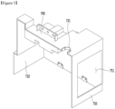
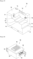
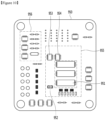
- a first step portion 732, a second stepped part 733, and a third stepped part 735 may be successively provided backward from the front surface.
- a controller placing part 734 having the same height as the third stepped part is disposed on the second stepped part 733. According to this structure, the controller 900 may be disposed in parallel to the third stepped part 735 and the controller placing part 734.
- a large cover suction hole (see reference numeral 751 of Fig. 5 ) that is opened in the rear surface of the machine room cover 700 may be provided.
- a predetermined space may be provided between the rear surface of the machine room cover 700 and the rear surface of the console space 4.
- the cover suction hole 751 is provided in the rear surface 750 of the machine room cover 700. Air may be introduced forward from the rear surface of the machine room through the cover suction hole 751.
- the air introduced through the cover suction hole 751 may pass through the condensation module 500 to perform a condensation action of the refrigerant and thereby to be heated. Then, heat exchange action with respect to the driver and the expansion valve is performed. Thereafter, the refrigerant cools the compressor 201 and is discharged to the bottom surface of the machine room 200.
- a path through which the air suctioned from the right side through the suction portion 5 moves in the right direction from the cavity 100 to the machine room a path through which the moves from a region of machine room to the outside of the machine room, a path through which the air moves downward from an upper side of the machine room, a path through which the air moves forward from the inside of the machine room, a path through which the air moves downward from a front portion of the machine room, and a path through which the air moves from the machine room to the left side and then exhausted through the exhaust port 6.
- the reason is for preventing the hot air discharged to the outside of the machine room cover 700 does not recirculate to the suction-side of the condensation fan 501.
- the inside of the machine room surrounded by the machine room cover 700 may not communicate with the other sides except for the passage guide 81.
- the air discharged from the inside of the machine room 200 may not be discharged to the outside of the console space 4, but flow again into the inside of the machine room 200 to have great influence on the efficiency reduction of the refrigeration system.
- the air in the machine room may be discharged only through the flow guide 81 and not discharged to the other parts, and the air discharged through the flow guide 81 may be smoothly discharged to the exhaust port. If the air discharged through the passage guide is stagnated in the console space 4 without being discharged through the exhaust port 6, some of the air may eventually flow into the machine room 200. This causes severe cooling efficiency deterioration.
- the maximum rotation rate of the condensing fan 501 is preferably limited to about 2,000 rpm.
- the upper surface 730 is provided with stepped parts 732, 733, and 735 to smoothly flow the air and prevent problem in positions of the internal parts disposed inside the machine room and the external parts disposed outside the machine room from occurring.
- Fig. 8 is a perspective view of the controller
- Fig. 9 is an exploded perspective view of the controller.
- a heat sink 930 is provided which comes into contact with a heat generation portion of the control board 950 to promote the heat radiation of the control board 950.
- a cover hole 921 that is opened to a top surface is provided in the upper cover 920. The heat sink 930 is exposed to the outside through the cover hole 921.
- the refrigerator control circuit 956 may perform functions such as door opening/ closing, a fan operation, data storage, state determination, and a command.
- the compressor control circuit 951 is configured to control rotation of a motor of the compressor and has a high heat generation value due to execution of the switching operation and supply of the driving current.
- a temperature sensor 952 is provided in the vicinity of the compressor control circuit 951 to stop the compressor 201 when the temperature sensor 952 senses a temperature equal to or higher than a threshold value. Therefore, it is important that the temperature sensor 952 should not rise above the threshold value.
- Another circuit part having a high heat generation value in the control board is a DC-DC converter 953 and a diode 954 for boosting a voltage from about 12 volts to about 40 volts.
- a DC-DC converter 953 and a diode 954 for boosting a voltage from about 12 volts to about 40 volts.
- Fig. 11 is a block diagram for explaining control of the vehicle refrigerator.
- a condensation fan 281 that draws an air flow inside the machine room and a compressor 282 that draws a refrigerant flow from the refrigeration system are provided in the machine room 200.
- the condensation fan 281 and the compressor 282 are controlled by the control unit 961.
- a relay switch 966 operates under the control of the control unit 961, and voltage regulators 965 and 967 control an operation of fans 182 and 281.
- An UART port for inputting data may be provided on the control board 950. Necessary data may be stored by the UART port.
- a compressor control circuit for switching the compressor 282 and supplying a high voltage to the compressor 282 is provided in plurality of chips on the board between the compressor 282 and the controller 961.
- the compressor control circuit 951 may operate by a control command of the control unit 961 to supply energy to the compressor 282.
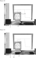
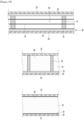
- connection passage 65 may be provided in a path between the passage guide 81 and the exhaust port 6.
- the connection passage 65 is a member for connecting the passage guide 81 provided in the refrigerator bottom frame 8 to an inlet end of the exhaust port 6.
- the exhaust port has a width W2 greater than that of the passage guide 81. According to this, the air discharged from the passage guide 81 is diffused, and a flow velocity thereof is slowed down so that an effect of preventing direct contact with the assistant driver is obtained. Also, a smooth exhaust operation may be obtained, and the recirculation of the discharged air may be suppressed.
- the spacing part between the refrigerator bottom frame 8 and the console space 4 is blocked by the blocking wall 66, and the discharged air does not flow therebetween.
- hot air recirculated to the machine room 200 i.e., the inlet side of the condensation module 500, may be removed.
- the blocking wall 66 may be a preferred means for preventing the recirculation of the exhaust air of the machine room.
- connection passage 65 extends to the vicinity of the inlet end of the exhaust port 6 and does not come into contact with the exhaust port 6. This is because the discharged air of the connection passage 65 is directly discharged through the exhaust port 6, thereby preventing a large flow rate from being generated and causing the user to feel uncomfortable. Also, it is possible to prevent the recirculation of the machine room discharge air by such a structure.
- connection passage 65 may have a size greater than that of the inlet side of the connection passage 65.
- connection passage 65 may act as a diffuser by itself.
- the outlet end of the connection passage 65 may be aligned with the size of the exhaust port 6, and the outlet end of the connection passage 65 may come into contact with the inlet end of the exhaust port 6 when the diffuser is employed. In this case, the discomfort of the assistant driver may be eliminated.
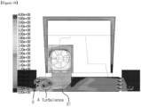
- the turbulence region A is generated in the discharge part of the passage guide 81 due to the size of the excess flow guide and the influence of the turbulence region A is generated between the refrigerator bottom frame 8 and the console space 4 so that the flow reaches the spacing part. As a result, it is seen that recirculation of the discharged air occurs.
- the third space is provided as a space in the vacuum state
- the first and second plate members 10 and 20 receive a force contracting in a direction in which they approach each other due to a force corresponding to a pressure difference between the first and second spaces. Therefore, the vacuum space part 50 may be deformed in a direction in which it is reduced. In this case, adiabatic loss may be caused due to an increase in amount of heat radiation, caused by the contraction of the vacuum space part 50, and an increase in amount of heat conduction, caused by contact between the plate members 10 and 20.
- a supporting unit 30 may be provided to reduce the deformation of the vacuum space part 50.
- the supporting unit 30 includes bars 31.
- the bars 31 may extend in a direction substantially vertical to the first and second plate members 10 and 20 so as to support a distance between the first and second plate members 10 and 20.
- a support plate 35 may be additionally provided to at least one end of the bar 31.
- the support plate 35 connects at least two bars 31 to each other, and may extend in a direction horizontal to the first and second plate members 10 and 20.
- the support plate 35 may be provided in a plate shape, or may be provided in a lattice shape such that its area contacting the first or second plate member 10 or 20 is decreased, thereby reducing heat transfer.
- the bars 31 and the support plate 35 are fixed to each other at at least one portion, to be inserted together between the first and second plate members 10 and 20.
- the support plate 35 contacts at least one of the first and second plate members 10 and 20, thereby preventing deformation of the first and second plate members 10 and 20.
- a total sectional area of the support plate 35 is provided to be greater than that of the bars 31, so that heat transferred through the bars 31 may be diffused through the support plate 35.
- a material of the supporting unit 30 may include a resin selected from the group consisting of PC, glass fiber PC, low outgassing PC, PPS, and LCP so as to obtain high compressive strength, low outgassing and water absorption, low thermal conductivity, high compressive strength at high temperature, and excellent machinability.
- the first and second plate members 10 and 20 may be made of a stainless material capable of preventing corrosion and providing a sufficient strength.
- the stainless material has a relatively high emissivity of 0.16, and hence a large amount of radiation heat may be transferred.
- the supporting unit 30 made of the resin has a lower emissivity than the plate members, and is not entirely provided to inner surfaces of the first and second plate members 10 and 20. Hence, the supporting unit 30 does not have great influence on radiation heat. Therefore, the radiation resistance sheet 32 may be provided in a plate shape over a majority of the area of the vacuum space part 50 so as to concentrate on reduction of radiation heat transferred between the first and second plate members 10 and 20.
- the supporting unit 30 maintaining the vacuum space part 50 is not provided.
- the porous substance 33 is provided in a state in which it is surrounded by a film 34.
- the porous substance 33 may be provided in a state in which it is compressed so as to maintain the gap of the vacuum space part 50.
- the film 34 is made of, for example, a PE material, and may be provided in a state in which holes are formed therein.
- the shielding part 62 is provided at the exterior of the conductive resistance sheet 60.
- the conductive resistance sheet 60 when the conductive resistance sheet 60 is exposed to any one of the low-temperature space and the high-temperature space, the conductive resistance sheet 60 does not serve as a conductive resistor as well as the exposed portion thereof, which is not preferable.
- effective heat transfer coefficients (eK: effective K) (W/mK) of the surface conduction heat 1, the supporter conduction heat 2, the gas conduction heat 3, and the radiation transfer heat 4 may have an order of Math Figure 1 .
- the effective heat transfer coefficient (eK) is a value that may be measured using a shape and temperature differences of a target product.
- the effective heat transfer coefficient (eK) is a value that may be obtained by measuring a total heat transfer amount and a temperature at least one portion at which heat is transferred. For example, a calorific value (W) is measured using a heating source that may be quantitatively measured in the refrigerator, a temperature distribution (K) of the door is measured using heats respectively transferred through a main body and an edge of the door of the refrigerator, and a path through which heat is transferred is calculated as a conversion value (m), thereby evaluating an effective heat transfer coefficient.
- the thermal conductivity of the supporting unit is a material property of a material and may be obtained in advance.
- the sum of the gas conduction heat 3, and the radiation transfer heat 4 may be obtained by subtracting the surface conduction heat and the supporter conduction heat from the heat transfer amount of the entire vacuum adiabatic body.
- a ratio of the gas conduction heat 3, and the radiation transfer heat 4 may be obtained by evaluating radiation transfer heat when no gas conduction heat exists by remarkably lowering a vacuum degree of the vacuum space part 50.
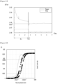
- Fig. 21 is a graph illustrating results obtained by observing a time and a pressure in a process of exhausting the inside of the vacuum adiabatic body when a supporting unit is used.
- the satisfaction of the user may be improved because the vehicle quickly provides food in a desired state by the user.
- a refrigerating or warming apparatus comprising:
- the vehicle according to example 12 further comprising a connection passage between an inlet end of the exhaust port and a discharge end of the passage guide.
Landscapes
- Engineering & Computer Science (AREA)
- Physics & Mathematics (AREA)
- Thermal Sciences (AREA)
- Mechanical Engineering (AREA)
- Chemical & Material Sciences (AREA)
- Combustion & Propulsion (AREA)
- General Engineering & Computer Science (AREA)
- Transportation (AREA)
- Devices That Are Associated With Refrigeration Equipment (AREA)
- Air-Conditioning For Vehicles (AREA)
- Compressor (AREA)
Applications Claiming Priority (3)
| Application Number | Priority Date | Filing Date | Title |
|---|---|---|---|
| KR1020170021560A KR102658454B1 (ko) | 2017-02-17 | 2017-02-17 | 냉온장고, 및 차량 |
| PCT/KR2018/001861 WO2018151494A1 (en) | 2017-02-17 | 2018-02-13 | Refrigerating or warming apparatus, and vehicle |
| EP18754627.0A EP3583000B1 (de) | 2017-02-17 | 2018-02-13 | Kühl- oder warmvorrichtung und fahrzeug |
Related Parent Applications (2)
| Application Number | Title | Priority Date | Filing Date |
|---|---|---|---|
| EP18754627.0A Division EP3583000B1 (de) | 2017-02-17 | 2018-02-13 | Kühl- oder warmvorrichtung und fahrzeug |
| EP18754627.0A Division-Into EP3583000B1 (de) | 2017-02-17 | 2018-02-13 | Kühl- oder warmvorrichtung und fahrzeug |
Publications (2)
| Publication Number | Publication Date |
|---|---|
| EP4538075A2 true EP4538075A2 (de) | 2025-04-16 |
| EP4538075A3 EP4538075A3 (de) | 2025-07-02 |
Family
ID=63169490
Family Applications (2)
| Application Number | Title | Priority Date | Filing Date |
|---|---|---|---|
| EP25160633.1A Pending EP4538075A3 (de) | 2017-02-17 | 2018-02-13 | Kühl- oder warmvorrichtung und fahrzeug |
| EP18754627.0A Active EP3583000B1 (de) | 2017-02-17 | 2018-02-13 | Kühl- oder warmvorrichtung und fahrzeug |
Family Applications After (1)
| Application Number | Title | Priority Date | Filing Date |
|---|---|---|---|
| EP18754627.0A Active EP3583000B1 (de) | 2017-02-17 | 2018-02-13 | Kühl- oder warmvorrichtung und fahrzeug |
Country Status (7)
| Country | Link |
|---|---|
| US (2) | US11618299B2 (de) |
| EP (2) | EP4538075A3 (de) |
| KR (3) | KR102658454B1 (de) |
| CN (3) | CN114523893B (de) |
| AU (1) | AU2018220496B2 (de) |
| RU (1) | RU2729140C1 (de) |
| WO (1) | WO2018151494A1 (de) |
Families Citing this family (3)
| Publication number | Priority date | Publication date | Assignee | Title |
|---|---|---|---|---|
| KR101738787B1 (ko) * | 2015-12-15 | 2017-06-08 | 엘지전자 주식회사 | 진공단열체, 저장고, 차량용 저장고, 및 차량 |
| WO2021245557A1 (en) | 2020-06-03 | 2021-12-09 | Dometic Sweden Ab | Refrigerator |
| KR20230106394A (ko) * | 2022-01-06 | 2023-07-13 | 한온시스템 주식회사 | 차량용 전동 압축기 및 이를 포함하는 열교환 모듈 |
Family Cites Families (34)
| Publication number | Priority date | Publication date | Assignee | Title |
|---|---|---|---|---|
| DE3328120C1 (de) * | 1983-08-04 | 1984-10-18 | Ernst 7500 Karlsruhe Gaus | Kuehlbox fuer Kraftfahrzeuge oder aehnliche mobile Einrichtungen,insbesondere fuer Personenkraftwagen |
| US4637222A (en) * | 1984-06-08 | 1987-01-20 | Nippondenso Co., Ltd. | Refrigerator for vehicle |
| US4759190A (en) * | 1987-04-22 | 1988-07-26 | Leonard Trachtenberg | Vehicle thermoelectric cooling and heating food and drink appliance |
| JPH0526563A (ja) | 1991-07-23 | 1993-02-02 | Toshiba Corp | 冷蔵庫 |
| RU5951U1 (ru) | 1996-11-13 | 1998-02-16 | Аозт "Экохол" | Автомобильный холодильник-нагреватель-подлокотник |
| JPH11223451A (ja) | 1998-02-09 | 1999-08-17 | Sharp Corp | 冷蔵庫及びその冷却機構 |
| JP3886295B2 (ja) | 1999-06-15 | 2007-02-28 | 松下冷機株式会社 | 冷凍システムのパワー制御装置およびコンプレッサ |
| US6763666B2 (en) | 2000-06-28 | 2004-07-20 | Textron Automotive Company Inc. | Console heating and cooling apparatus |
| CN2443869Y (zh) * | 2000-09-05 | 2001-08-22 | 胡春福 | 车用冰箱 |
| RU16715U1 (ru) | 2000-09-28 | 2001-02-10 | Дорошенко Сергей Павлович | Мини-холодильник для автомобиля "волга" |
| KR100848512B1 (ko) * | 2002-03-29 | 2008-07-25 | 삼성전자주식회사 | 김치냉장고 |
| CN1331770C (zh) | 2002-11-12 | 2007-08-15 | 牛晓军 | 纳米SiOx复合聚丙烯酰胺阳离子絮凝剂及其制备方法 |
| KR100506605B1 (ko) * | 2003-05-09 | 2005-08-08 | 삼성전자주식회사 | 냉장고 |
| CN2691933Y (zh) * | 2004-03-06 | 2005-04-13 | 江苏阪神电器股份有限公司 | 车载移动式冰柜 |
| KR100744504B1 (ko) | 2004-12-02 | 2007-08-01 | 엘지전자 주식회사 | 냉난방 시스템 |
| DE102004058196A1 (de) | 2004-12-02 | 2006-06-08 | BSH Bosch und Siemens Hausgeräte GmbH | Einbaukältegerät |
| JP3819014B2 (ja) | 2004-12-15 | 2006-09-06 | シャープ株式会社 | 冷蔵庫 |
| KR101319434B1 (ko) * | 2005-12-27 | 2013-10-17 | 한라비스테온공조 주식회사 | 열전소자 모듈을 이용한 자동차 후석측 냉온장장치 |
| DE102007011114A1 (de) * | 2007-03-07 | 2008-09-11 | BSH Bosch und Siemens Hausgeräte GmbH | Kältegerät |
| KR101387489B1 (ko) * | 2007-07-11 | 2014-04-21 | 엘지전자 주식회사 | 냉장고 |
| US20090058120A1 (en) * | 2007-08-29 | 2009-03-05 | Mazda Motor Corporation | Center console structure of vehicle |
| KR20110019074A (ko) * | 2009-08-19 | 2011-02-25 | 엘지전자 주식회사 | 냉장고 |
| CN102494465A (zh) | 2011-12-08 | 2012-06-13 | 合肥美的荣事达电冰箱有限公司 | 冰箱及用于冰箱的制冷装置 |
| CN203116352U (zh) | 2012-06-07 | 2013-08-07 | 太仓京和机电有限公司 | 提手与顶盖分离的机组和装有该机组的玄米冷藏保管箱 |
| KR101974360B1 (ko) * | 2012-07-06 | 2019-05-03 | 삼성전자주식회사 | 냉장고 |
| CN103453630B (zh) * | 2013-06-04 | 2015-12-09 | 湖南吉利汽车部件有限公司 | 一种车载冷暧贮藏箱 |
| CN105263753A (zh) | 2013-06-06 | 2016-01-20 | 捷温有限公司 | 车用饮料架 |
| KR101592708B1 (ko) | 2014-06-13 | 2016-02-15 | 현대자동차주식회사 | 냉온장 컵홀더 |
| KR102529853B1 (ko) | 2015-08-03 | 2023-05-08 | 엘지전자 주식회사 | 진공단열체, 진공단열체의 제조방법, 다공성물질패키지, 및 냉장고 |
| KR102529852B1 (ko) * | 2015-08-03 | 2023-05-08 | 엘지전자 주식회사 | 진공단열체 및 냉장고 |
| US10488083B2 (en) * | 2015-12-18 | 2019-11-26 | Friedrich Air Conditioning Co., Ltd. | Variable refrigerant package |
| CN205536749U (zh) | 2016-01-21 | 2016-08-31 | 周小能 | 容积可调的车载冰箱 |
| KR102658453B1 (ko) * | 2017-02-02 | 2024-04-17 | 엘지전자 주식회사 | 차량용 냉장고, 및 차량 |
| KR102658800B1 (ko) | 2017-02-02 | 2024-04-19 | 엘지전자 주식회사 | 차량용 냉장고, 및 차량 |
-
2017
- 2017-02-17 KR KR1020170021560A patent/KR102658454B1/ko active Active
-
2018
- 2018-02-13 CN CN202210152222.XA patent/CN114523893B/zh active Active
- 2018-02-13 EP EP25160633.1A patent/EP4538075A3/de active Pending
- 2018-02-13 EP EP18754627.0A patent/EP3583000B1/de active Active
- 2018-02-13 WO PCT/KR2018/001861 patent/WO2018151494A1/en not_active Ceased
- 2018-02-13 CN CN202210153185.4A patent/CN114523894B/zh active Active
- 2018-02-13 CN CN201880012558.8A patent/CN110300681B/zh active Active
- 2018-02-13 AU AU2018220496A patent/AU2018220496B2/en active Active
- 2018-02-13 RU RU2019129086A patent/RU2729140C1/ru active
- 2018-02-13 US US16/486,865 patent/US11618299B2/en active Active
-
2023
- 2023-02-10 US US18/108,254 patent/US20230182530A1/en active Pending
-
2024
- 2024-04-12 KR KR1020240049621A patent/KR102817801B1/ko active Active
-
2025
- 2025-05-13 KR KR1020250062118A patent/KR20250076473A/ko active Pending
Also Published As
| Publication number | Publication date |
|---|---|
| AU2018220496B2 (en) | 2022-07-14 |
| EP3583000A4 (de) | 2020-12-23 |
| CN114523893A (zh) | 2022-05-24 |
| US11618299B2 (en) | 2023-04-04 |
| CN110300681A (zh) | 2019-10-01 |
| WO2018151494A1 (en) | 2018-08-23 |
| EP3583000A1 (de) | 2019-12-25 |
| CN114523893B (zh) | 2023-12-12 |
| KR20240056691A (ko) | 2024-04-30 |
| US20230182530A1 (en) | 2023-06-15 |
| EP4538075A3 (de) | 2025-07-02 |
| RU2729140C1 (ru) | 2020-08-04 |
| RU2020124274A (ru) | 2020-09-09 |
| US20190381856A1 (en) | 2019-12-19 |
| CN110300681B (zh) | 2022-03-08 |
| CN114523894A (zh) | 2022-05-24 |
| KR20250076473A (ko) | 2025-05-29 |
| CN114523894B (zh) | 2023-11-28 |
| KR102658454B1 (ko) | 2024-04-17 |
| RU2020124274A3 (de) | 2022-01-17 |
| KR102817801B1 (ko) | 2025-06-09 |
| KR20180095280A (ko) | 2018-08-27 |
| AU2018220496A1 (en) | 2019-08-29 |
| EP3583000B1 (de) | 2025-04-02 |
Similar Documents
| Publication | Publication Date | Title |
|---|---|---|
| AU2021218201B2 (en) | Refrigerator for vehicle and vehicle | |
| US20230365044A1 (en) | Vacuum adiabatic body, refrigerating or warming apparatus, and vehicle | |
| US20230182530A1 (en) | Refrigerating or warming apparatus, and vehicle | |
| US12263772B2 (en) | Refrigerator for vehicle and vehicle | |
| RU2775367C2 (ru) | Устройство, имеющее функцию охлаждения и нагревания, и транспортное средство |
Legal Events
| Date | Code | Title | Description |
|---|---|---|---|
| PUAI | Public reference made under article 153(3) epc to a published international application that has entered the european phase |
Free format text: ORIGINAL CODE: 0009012 |
|
| STAA | Information on the status of an ep patent application or granted ep patent |
Free format text: STATUS: REQUEST FOR EXAMINATION WAS MADE |
|
| 17P | Request for examination filed |
Effective date: 20250227 |
|
| AC | Divisional application: reference to earlier application |
Ref document number: 3583000 Country of ref document: EP Kind code of ref document: P |
|
| AK | Designated contracting states |
Kind code of ref document: A2 Designated state(s): AL AT BE BG CH CY CZ DE DK EE ES FI FR GB GR HR HU IE IS IT LI LT LU LV MC MK MT NL NO PL PT RO RS SE SI SK SM TR |
|
| REG | Reference to a national code |
Ref country code: DE Ref legal event code: R079 Free format text: PREVIOUS MAIN CLASS: B60H0001000000 Ipc: B60N0003100000 |
|
| PUAL | Search report despatched |
Free format text: ORIGINAL CODE: 0009013 |
|
| AK | Designated contracting states |
Kind code of ref document: A3 Designated state(s): AL AT BE BG CH CY CZ DE DK EE ES FI FR GB GR HR HU IE IS IT LI LT LU LV MC MK MT NL NO PL PT RO RS SE SI SK SM TR |
|
| RIC1 | Information provided on ipc code assigned before grant |
Ipc: B60H 1/00 20060101ALI20250528BHEP Ipc: F25D 31/00 20060101ALI20250528BHEP Ipc: B60N 3/10 20060101AFI20250528BHEP |