EP4537795A2 - Stentfedern und stents zur reparatur von rohren - Google Patents
Stentfedern und stents zur reparatur von rohren Download PDFInfo
- Publication number
- EP4537795A2 EP4537795A2 EP24221715.6A EP24221715A EP4537795A2 EP 4537795 A2 EP4537795 A2 EP 4537795A2 EP 24221715 A EP24221715 A EP 24221715A EP 4537795 A2 EP4537795 A2 EP 4537795A2
- Authority
- EP
- European Patent Office
- Prior art keywords
- stent
- stent spring
- spring
- configuration
- strands
- Prior art date
- Legal status (The legal status is an assumption and is not a legal conclusion. Google has not performed a legal analysis and makes no representation as to the accuracy of the status listed.)
- Pending
Links
Images


Classifications
-
- F—MECHANICAL ENGINEERING; LIGHTING; HEATING; WEAPONS; BLASTING
- F16—ENGINEERING ELEMENTS AND UNITS; GENERAL MEASURES FOR PRODUCING AND MAINTAINING EFFECTIVE FUNCTIONING OF MACHINES OR INSTALLATIONS; THERMAL INSULATION IN GENERAL
- F16L—PIPES; JOINTS OR FITTINGS FOR PIPES; SUPPORTS FOR PIPES, CABLES OR PROTECTIVE TUBING; MEANS FOR THERMAL INSULATION IN GENERAL
- F16L55/00—Devices or appurtenances for use in, or in connection with, pipes or pipe systems
- F16L55/16—Devices for covering leaks in pipes or hoses, e.g. hose-menders
- F16L55/162—Devices for covering leaks in pipes or hoses, e.g. hose-menders from inside the pipe
- F16L55/163—Devices for covering leaks in pipes or hoses, e.g. hose-menders from inside the pipe a ring, a band or a sleeve being pressed against the inner surface of the pipe
-
- F—MECHANICAL ENGINEERING; LIGHTING; HEATING; WEAPONS; BLASTING
- F16—ENGINEERING ELEMENTS AND UNITS; GENERAL MEASURES FOR PRODUCING AND MAINTAINING EFFECTIVE FUNCTIONING OF MACHINES OR INSTALLATIONS; THERMAL INSULATION IN GENERAL
- F16L—PIPES; JOINTS OR FITTINGS FOR PIPES; SUPPORTS FOR PIPES, CABLES OR PROTECTIVE TUBING; MEANS FOR THERMAL INSULATION IN GENERAL
- F16L55/00—Devices or appurtenances for use in, or in connection with, pipes or pipe systems
- F16L55/16—Devices for covering leaks in pipes or hoses, e.g. hose-menders
- F16L55/168—Devices for covering leaks in pipes or hoses, e.g. hose-menders from outside the pipe
- F16L55/17—Devices for covering leaks in pipes or hoses, e.g. hose-menders from outside the pipe by means of rings, bands or sleeves pressed against the outside surface of the pipe or hose
-
- F—MECHANICAL ENGINEERING; LIGHTING; HEATING; WEAPONS; BLASTING
- F16—ENGINEERING ELEMENTS AND UNITS; GENERAL MEASURES FOR PRODUCING AND MAINTAINING EFFECTIVE FUNCTIONING OF MACHINES OR INSTALLATIONS; THERMAL INSULATION IN GENERAL
- F16L—PIPES; JOINTS OR FITTINGS FOR PIPES; SUPPORTS FOR PIPES, CABLES OR PROTECTIVE TUBING; MEANS FOR THERMAL INSULATION IN GENERAL
- F16L55/00—Devices or appurtenances for use in, or in connection with, pipes or pipe systems
- F16L55/18—Appliances for use in repairing pipes
-
- F—MECHANICAL ENGINEERING; LIGHTING; HEATING; WEAPONS; BLASTING
- F16—ENGINEERING ELEMENTS AND UNITS; GENERAL MEASURES FOR PRODUCING AND MAINTAINING EFFECTIVE FUNCTIONING OF MACHINES OR INSTALLATIONS; THERMAL INSULATION IN GENERAL
- F16L—PIPES; JOINTS OR FITTINGS FOR PIPES; SUPPORTS FOR PIPES, CABLES OR PROTECTIVE TUBING; MEANS FOR THERMAL INSULATION IN GENERAL
- F16L57/00—Protection of pipes or objects of similar shape against external or internal damage or wear
- F16L57/02—Protection of pipes or objects of similar shape against external or internal damage or wear against cracking or buckling
-
- A—HUMAN NECESSITIES
- A61—MEDICAL OR VETERINARY SCIENCE; HYGIENE
- A61F—FILTERS IMPLANTABLE INTO BLOOD VESSELS; PROSTHESES; DEVICES PROVIDING PATENCY TO, OR PREVENTING COLLAPSING OF, TUBULAR STRUCTURES OF THE BODY, e.g. STENTS; ORTHOPAEDIC, NURSING OR CONTRACEPTIVE DEVICES; FOMENTATION; TREATMENT OR PROTECTION OF EYES OR EARS; BANDAGES, DRESSINGS OR ABSORBENT PADS; FIRST-AID KITS
- A61F2/00—Filters implantable into blood vessels; Prostheses, i.e. artificial substitutes or replacements for parts of the body; Appliances for connecting them with the body; Devices providing patency to, or preventing collapsing of, tubular structures of the body, e.g. stents
- A61F2/82—Devices providing patency to, or preventing collapsing of, tubular structures of the body, e.g. stents
- A61F2/86—Stents in a form characterised by the wire-like elements; Stents in the form characterised by a net-like or mesh-like structure
- A61F2/90—Stents in a form characterised by the wire-like elements; Stents in the form characterised by a net-like or mesh-like structure characterised by a net-like or mesh-like structure
- A61F2/91—Stents in a form characterised by the wire-like elements; Stents in the form characterised by a net-like or mesh-like structure characterised by a net-like or mesh-like structure made from perforated sheets or tubes, e.g. perforated by laser cuts or etched holes
- A61F2/915—Stents in a form characterised by the wire-like elements; Stents in the form characterised by a net-like or mesh-like structure characterised by a net-like or mesh-like structure made from perforated sheets or tubes, e.g. perforated by laser cuts or etched holes with bands having a meander structure, adjacent bands being connected to each other
Definitions
- This disclosure relates to the field of pipe repair. More specifically, this disclosure relates to stent springs and stents for repairing a pipe.
- Piping systems including municipal water systems, can develop breaks in pipe walls that can cause leaking.
- Example of breaks in a pipe wall can include radial cracks, axial cracks, point cracks, etc. Repairing a break in a pipe wall often requires the piping system to be shut off, which can be inconvenient for customers and costly for providers. Further, repairs can necessitate grandiose construction, including the digging up of streets, sidewalks, and the like, which can be costly and time-consuming.
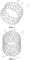
- a stent spring for repairing a pipe comprising a substantially tubular mesh structure defining a void, the void defining a central axis, the mesh structure comprising one or more strands, the one or more strands defining a plurality of openings, wherein the stent spring is configurable in an expanded stent spring configuration and a compressed stent spring configuration; and a tab extending radially inward from the mesh structure into the void, the tab defining a tab opening.
- a stent spring for repairing a pipe comprising a substantially tubular mesh structure comprising one or more strands, the one or more strands comprising a spring material, wherein the stent spring is expandable and compressible between an expanded stent spring configuration and a compressed stent spring configuration; and an elastic wire connected to the one or more strands, the elastic wire configured to increase a flexibility of the stent spring.
- the stent 100 can be expanded within a pipe (not shown) such that the seal 170 can engage an inner wall (not shown) of the pipe where a crack or other damage is present, in order to create a watertight seal between the stent 100 and the inner wall of the pipe to prevent leaking at the damage site.
- the stent spring 120 can be formed from a spring material.
- the stent spring 120 can comprise a metal material, such as stainless steel, spring steel, aluminum, nitinol, cobalt chromium, or any other suitable material.
- the stent spring 120 can be formed from a plastic material, such as, for example, nylon, POM (polyoxymethylene), or PVC (polyvinyl chloride).
- the stent spring 120 can be formed from a carbon fiber material.
- the material can be an NSF certified material that can comply with various public health safety standards. For example, in some aspects, the material can be approved as safe for use in drinking-water applications.
- the seal 170 can wrap around a circumference of the stent spring 120, and the inner surface 174 of the seal 170 can engage the outer surface 126 of the stent spring 120.
- the seal 170 can cover the entire outer surface 126 of the stent spring 120, as shown.
- the seal 170 can cover only a portion of the outer surface 126 of the stent spring 120.
- the seal 170 may not wrap entirely around the circumference of the stent spring 120.
- the seal 170 can fit snugly on the stent spring 120.
- the seal 170 can be coupled to the stent spring 120 by a fastener (not shown), such as, for example, stitching, adhesives, ties, or any other suitable fastener known in the art.
- a compression force (i.e., a pushing force, a pulling force, or any other suitable force) can be applied to the stent 100 by a compression mechanism to bias the stent 100, including the stent spring 120 and the seal 170, to the compressed configuration.
- a compression mechanism to bias the stent 100, including the stent spring 120 and the seal 170, to the compressed configuration.
- the compression force can overcome the spring force, and the seal 170 and stent spring 120 can compress or fold radially inward towards the void 130 to define a smaller stent diameter D 1 and a smaller overall stent volume than in the expanded configuration.
- the reduced stent diameter D 1 and stent volume in the compressed configuration can allow for easier insertion of the stent 100 into the pipe or a pipeline (not shown) and easier navigation of the stent 100 through the pipe or pipeline.
- the stent spring 120 can bias the stent 100 back to the expanded configuration.
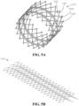
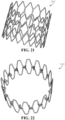
- some of the openings 142a can substantially define a diamond shape, and some other openings 142b can substantially define a series of diamond and half-diamond shapes.
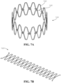
- Figure 7A illustrates still another aspect of the stent spring 120 in the rolled configuration
- Figure 7B illustrates the stent spring 120 of Figure 7A in the unrolled configuration.
- the openings 142 can substantially define an elongated hexagonal shape.
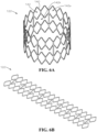
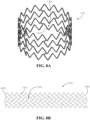
- Figure 8A illustrates the stent spring 120 in the rolled configuration, according to a further aspect of the present disclosure
- Figure 8B illustrates the stent spring 120 of Figure 8A in the unrolled configuration.
- the openings 142 can substantially define a chevron pattern.
- Figure 9A illustrates the stent spring 120 in the rolled configuration
- Figure 9B illustrates the stent spring 120 of Figure 9A in the unrolled configuration
- the openings 142 can substantially define an elongated hexagonal shape
- the stent spring 120 can comprise a spring steel material.
- Example aspects can be coated with a rubber or liquid metal material, zinc-nickel material, phosphate, electrophoretic paint (e-coating), polyester, or fusion-bonded epoxy (FBE), as described above.
- the stent spring 120 can comprise a stainless steel material, or any other suitable spring material.
- Figure 10 illustrates still another aspect of the stent spring 120 the rolled configuration.
- the openings 142 can substantially define an elongated hexagonal shape.
- the stent spring 120 can comprise a carbon fiber material.
- the stent spring 120 comprises the tabs 960 extending radially inward towards the void 130.
- the tabs 960 can be formed extending inward rather than having to be bent inwards, as may be required by the aspect of Figure 9A .
- Each of the tabs 960 can define one of the tab openings 962 therethrough.
- the wire can be dissolved by electricity, chemicals, water, or any other suitable dissolving mechanism.
- the compression mechanism can be a hose clamp.
- the hose clamp or other compression mechanism can comprise a worm drive.
- Figure 11 illustrates another example aspect of the stent spring 120 in the rolled configuration.
- the present stent spring 120 can comprise an inner stent spring 1122 aligned and connected with an outer stent spring 1124 to provide increased stiffness of the stent spring 120, while maintaining flexibility of the stent spring 120.
- Each of the inner stent spring 1122 and outer stent spring 1124 of the present aspect can be substantially similar in shape to the stent spring 120 illustrated in Figure 10 ; however, in other aspects, the inner and outer stent springs 1122,1124 can be differently shaped.
- the inner and outer stent springs 1122,1124 can be formed from carbon fiber, and in another example aspect, the inner and outer stent springs 1122,1124 can be formed from nylon. In other aspects, the inner and outer stent springs 1122,1124 can be formed from any suitable material, including but not limited to stainless steel, spring steel, aluminum, nitinol, cobalt chromium, POM (polyoxymethylene), and PVC (polyvinyl chloride). According to example aspects, the inner and outer stent springs can be joined together at a plurality of upper bends 1102 and lower bends 1104 thereof, as shown.
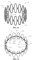
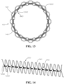
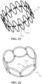
- Figures 12 and 13 illustrates an example aspect of the stent spring 120 in the rolled configuration, wherein the tabs 960 are formed as hollow cylindrical structures 1262 each defining the tab opening 962 extending therethrough.
- a coil spring 1220 can extend through the tab openings 962, as shown.
- the coil spring 1220 can define a coil spring force.
- the coil spring 1220 can be compressed in the compressed stent spring configuration and can be expanded in the expanded stent spring configuration.
- a compression force e.g. a pushing force, tension or pulling force, or any other suitable force
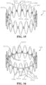
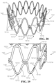
- Figures 15 and 16 illustrates an example aspect of the stent spring 120 in the rolled configuration, according to another aspect of the present disclosure.
- the stent spring 120 can be similar to the stent spring 120 illustrated Figure 10 .
- the stent spring 120 of the present aspect can further comprise a wire or wires 1510 connected to one or more of the strands 140 of the stent spring 120.
- the wires 1510 can be a plurality of Nitinol super-elastic wires 1512, which can be configured to provide added flexibility to the stent spring 120.
- Figures 18 and 19 illustrates another aspect, wherein each of the wires 1510 can be positioned on an inner periphery 1810 of the stent spring 120 proximate to an upper bend 1812 or lower bend 1814 thereof.
- the wires 1510 can be connected to the stent spring 120 by an adhesive, or other fastener, and the first and second ends 1514,1516 of the wires 1510 do not extend into the strands 140.
- the first and second ends 1514,1516 of each of the wires 1510 can engage the first and second grooves (not shown) formed in a corresponding strand 140 to connect the wire 1510 to the stent spring 120.
- Example aspects of the stent spring 120 can comprise a coating, such as, for example, a rubber coating.
- the stent spring 120 can be coated in a Plasti Dip ® coating.
- a Plasti Dip ® coating is a synthetic rubber coating that can be applied by spraying, brushing, dipping, or the like, and which can be configured to air dry.
- the Plasti Dip ® material can be non-slip, flexible, durable, and insulating material in some aspects.
- the stent spring 120 can be coated in a Flex Seal ® coating.
- the Flex Seal ® coating is a synthetic rubber coating similar to the Plasti Dip ® coating.
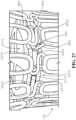
- the compression disc 2510 can further comprise a plurality of connectors 2620 generally received between the upper disc 2512 and lower disc 2712 and proximate to the outer side edge 2518 of the compression disc 2510.
- a head 2622 of each of the connectors 2620 can be configured to extend into a corresponding one of the disc slots 2516.
- an inner end 2662 of each of the tabs 960 can be pushed past the head 2622 of the corresponding connector 2620 and into the corresponding disc slot 2516, such that the head 2622 of each connector 2620 extends through the tab opening 962 (shown in Figure 9A ) of the corresponding tab 960.
- a stent spring for repairing a pipe can comprise a substantially tubular mesh structure defining a void, the void can define a central axis, the mesh structure can comprise one or more strands, and the one or more strands can define a plurality of openings.
- the stent spring can be configurable in an expanded stent spring configuration and a compressed stent spring configuration.
- the stent spring can further comprise a tab extending radially inward from the mesh structure into the void, and the tab can define a tab opening.
- the stent spring can comprise an inner stent spring connected to an outer stent spring, the inner stent spring can comprise the mesh structure and the tab, and the outer stent spring can be configured to increase a stiffness of the inner stent spring.
- the elastic wire can define a first end and a second end, the first end of the elastic wire can engage a first one of the strands, and the second end of the elastic wire can engage a second one of the strands.
- the first one of the strands can define a first groove
- the second one of the strands can define a second groove
- the first end can be received within the first groove
- the second end can be received within the second groove.
- the elastic wire can define a middle section between the first end and second end, and at least a portion of the middle section can be exposed.
- the elastic wire can be positioned on an inner periphery of the stent spring.
- a method for retaining a stent in a compressed configuration can comprise providing a stent, wherein the stent can comprise a stent spring, a seal, and a tab extending radially inward from the stent spring.
- the method can further comprise biasing the stent to a compressed configuration and engaging the tab with a compression mechanism to retain the stent in the compressed configuration.
- a stent in another exemplary aspect, can comprise a stent spring and a seal wrapped around a circumference of the stent spring, the stent spring can define a substantially tubular mesh structure, the stent can be configurable in an expanded configuration and a compressed configuration, and the stent spring can bias the stent to the expanded configuration.
Landscapes
- Engineering & Computer Science (AREA)
- General Engineering & Computer Science (AREA)
- Mechanical Engineering (AREA)
- Media Introduction/Drainage Providing Device (AREA)
Priority Applications (1)
| Application Number | Priority Date | Filing Date | Title |
|---|---|---|---|
| EP26161120.6A EP4726246A2 (de) | 2019-02-19 | 2020-02-18 | Stentfedern und stents zur reparatur von rohren |
Applications Claiming Priority (4)
| Application Number | Priority Date | Filing Date | Title |
|---|---|---|---|
| US201962807264P | 2019-02-19 | 2019-02-19 | |
| US201962834168P | 2019-04-15 | 2019-04-15 | |
| PCT/US2020/018593 WO2020172136A1 (en) | 2019-02-19 | 2020-02-18 | Stent springs and stents for repairing pipes |
| EP20758706.4A EP3928022B1 (de) | 2019-02-19 | 2020-02-18 | Stentfedern und stents zur reparatur von rohren |
Related Parent Applications (2)
| Application Number | Title | Priority Date | Filing Date |
|---|---|---|---|
| EP20758706.4A Division-Into EP3928022B1 (de) | 2019-02-19 | 2020-02-18 | Stentfedern und stents zur reparatur von rohren |
| EP20758706.4A Division EP3928022B1 (de) | 2019-02-19 | 2020-02-18 | Stentfedern und stents zur reparatur von rohren |
Related Child Applications (1)
| Application Number | Title | Priority Date | Filing Date |
|---|---|---|---|
| EP26161120.6A Division EP4726246A2 (de) | 2019-02-19 | 2020-02-18 | Stentfedern und stents zur reparatur von rohren |
Publications (2)
| Publication Number | Publication Date |
|---|---|
| EP4537795A2 true EP4537795A2 (de) | 2025-04-16 |
| EP4537795A3 EP4537795A3 (de) | 2025-08-20 |
Family
ID=72041948
Family Applications (6)
| Application Number | Title | Priority Date | Filing Date |
|---|---|---|---|
| EP22204247.5A Active EP4148316B1 (de) | 2019-02-19 | 2020-02-18 | Stentfedern zur reparatur von rohren |
| EP20758706.4A Active EP3928022B1 (de) | 2019-02-19 | 2020-02-18 | Stentfedern und stents zur reparatur von rohren |
| EP24221715.6A Pending EP4537795A3 (de) | 2019-02-19 | 2020-02-18 | Stentfedern und stents zur reparatur von rohren |
| EP24221702.4A Pending EP4509097A3 (de) | 2019-02-19 | 2020-02-18 | Stentfedern und stents zur reparatur von rohren |
| EP26161120.6A Pending EP4726246A2 (de) | 2019-02-19 | 2020-02-18 | Stentfedern und stents zur reparatur von rohren |
| EP24221729.7A Pending EP4512376A3 (de) | 2019-02-19 | 2020-02-18 | Stentfedern und stents zur reparatur von rohren |
Family Applications Before (2)
| Application Number | Title | Priority Date | Filing Date |
|---|---|---|---|
| EP22204247.5A Active EP4148316B1 (de) | 2019-02-19 | 2020-02-18 | Stentfedern zur reparatur von rohren |
| EP20758706.4A Active EP3928022B1 (de) | 2019-02-19 | 2020-02-18 | Stentfedern und stents zur reparatur von rohren |
Family Applications After (3)
| Application Number | Title | Priority Date | Filing Date |
|---|---|---|---|
| EP24221702.4A Pending EP4509097A3 (de) | 2019-02-19 | 2020-02-18 | Stentfedern und stents zur reparatur von rohren |
| EP26161120.6A Pending EP4726246A2 (de) | 2019-02-19 | 2020-02-18 | Stentfedern und stents zur reparatur von rohren |
| EP24221729.7A Pending EP4512376A3 (de) | 2019-02-19 | 2020-02-18 | Stentfedern und stents zur reparatur von rohren |
Country Status (3)
| Country | Link |
|---|---|
| US (3) | US11353154B2 (de) |
| EP (6) | EP4148316B1 (de) |
| WO (1) | WO2020172136A1 (de) |
Families Citing this family (8)
| Publication number | Priority date | Publication date | Assignee | Title |
|---|---|---|---|---|
| US10641427B2 (en) | 2018-04-03 | 2020-05-05 | Mueller International, Llc | Stents and methods for repairing pipes |
| EP4148316B1 (de) | 2019-02-19 | 2026-03-11 | Mueller International, LLC | Stentfedern zur reparatur von rohren |
| US11079058B2 (en) | 2019-03-15 | 2021-08-03 | Mueller International , LLC | Stent with coiled spring |
| US11187366B2 (en) | 2019-03-15 | 2021-11-30 | Mueller International, Llc | Stent for repairing a pipe |
| US11326731B2 (en) | 2019-04-24 | 2022-05-10 | Mueller International, Llc | Pipe repair assembly |
| US11391405B2 (en) | 2019-08-09 | 2022-07-19 | Mueller International, Llc | Deployment probe for pipe repair device |
| US11802646B2 (en) | 2019-08-09 | 2023-10-31 | Mueller International, Llc | Pipe repair device |
| US20230338175A1 (en) * | 2022-04-26 | 2023-10-26 | Accumedical Beijing Ltd. | Repositionable intracranial stent with retrieval mechanism |
Family Cites Families (66)
| Publication number | Priority date | Publication date | Assignee | Title |
|---|---|---|---|---|
| US3656771A (en) | 1970-12-11 | 1972-04-18 | Irrigation Accessories Co | Flexible seal assembly for spigot and bell conduit joint |
| US3895652A (en) | 1974-01-11 | 1975-07-22 | Roger G Zach | Diametrically expansible coil spring conduit plug |
| US4426095A (en) | 1981-09-28 | 1984-01-17 | Concrete Pipe & Products Corp. | Flexible seal |
| US4589447A (en) | 1983-08-03 | 1986-05-20 | Owens-Corning Fiberglas Corporation | Method of depositing a membrane within a conduit |
| EP0159300A1 (de) | 1984-03-30 | 1985-10-23 | Stig Westman | Reparaturhülse für Rohre |
| DE3610626A1 (de) | 1986-03-29 | 1987-10-08 | Norske Stats Oljeselskap | Vorrichtung zum erzeugen von radial auf eine zylindrische flaeche wirkenden kraeften, insbesondere anstell- oder haltekraeften |
| US5119862A (en) | 1988-10-31 | 1992-06-09 | Link-Pipe Technlogies, Inc. | Conduit repair apparatus |
| US4927189A (en) | 1989-04-10 | 1990-05-22 | Burkit John W | Internal expansion coupling device |
| CA2022301C (en) | 1989-08-14 | 1996-08-06 | Takayuki Kawafuji | Liner for pipeline repair and method for repairing pipelines |
| US5351720A (en) | 1992-03-10 | 1994-10-04 | Link-Pipe, Inc. | Apparatus for repairing conduits |
| JP2660101B2 (ja) * | 1992-05-08 | 1997-10-08 | シュナイダー・(ユーエスエイ)・インコーポレーテッド | 食道ステント及び運搬具 |
| ES2114964T3 (es) * | 1993-04-23 | 1998-06-16 | Schneider Europ Ag | Endoprotesis con una capa de recubrimiento de material elastico y metodo para aplicar la capa sobre la endoprotesis. |
| CA2192520A1 (en) * | 1996-03-05 | 1997-09-05 | Ian M. Penn | Expandable stent and method for delivery of same |
| US5624124A (en) | 1996-07-15 | 1997-04-29 | Fmc Corporation | Bore seal assembly with wear ring having curvilinear spring support surface |
| WO1998020810A1 (en) * | 1996-11-12 | 1998-05-22 | Medtronic, Inc. | Flexible, radially expansible luminal prostheses |
| DK174814B1 (da) | 1998-02-25 | 2003-12-01 | Cook William Europ | Stentaggregat |
| DK1087727T3 (da) | 1998-06-02 | 2005-01-31 | Cook Inc | Flersidet, intraluminal, medicinsk anordning |
| US6820653B1 (en) | 1999-04-12 | 2004-11-23 | Carnegie Mellon University | Pipe inspection and repair system |
| KR100786028B1 (ko) | 2000-02-03 | 2007-12-17 | 쿡 인코포레이티드 | 이식가능한 혈관장치 |
| US7267141B1 (en) * | 2000-06-05 | 2007-09-11 | Milliken & Company | Method of on-site production of novel textile reinforced thermoplastic or thermoset pipes |
| WO2001096092A1 (en) * | 2000-06-09 | 2001-12-20 | Fiberliner Networks | Method and apparatus for lining a conduit |
| NO335594B1 (no) | 2001-01-16 | 2015-01-12 | Halliburton Energy Serv Inc | Ekspanderbare anordninger og fremgangsmåte for disse |
| US6648071B2 (en) * | 2001-01-24 | 2003-11-18 | Schlumberger Technology Corporation | Apparatus comprising expandable bistable tubulars and methods for their use in wellbores |
| US6712556B2 (en) | 2001-05-18 | 2004-03-30 | G. Gregory Penza | Method and apparatus for routing cable in existing pipelines |
| EP1399200B2 (de) | 2001-06-11 | 2014-07-02 | Boston Scientific Limited | Komposit eptfe/textil prothese |
| US8488290B2 (en) | 2001-06-15 | 2013-07-16 | George M. Kauffman | Protective device |
| WO2003018100A1 (en) | 2001-08-22 | 2003-03-06 | Hasan Semih Oktay | Flexible mems actuated controlled expansion stent |
| ATE310559T1 (de) | 2002-05-29 | 2005-12-15 | Cook William A Australia | Trigger-draht system für eine prothesenplazierungsvorrichtung |
| US7611528B2 (en) | 2003-01-24 | 2009-11-03 | Medtronic Vascular, Inc. | Stent-graft delivery system |
| US7776078B2 (en) | 2003-05-22 | 2010-08-17 | Boston Scientfic Scimed, Inc. | Catheter balloon with improved retention |
| DE10357061B4 (de) * | 2003-12-04 | 2005-09-08 | Tracto-Technik Gmbh | Schneidsystem, Vorrichtung und Verfahren zum Zerteilen von Rohren |
| US20050212220A1 (en) | 2004-03-26 | 2005-09-29 | Stamped Fittings, Inc. | Gasket for duct, pipe and tube joints |
| JP2005278993A (ja) * | 2004-03-30 | 2005-10-13 | Terumo Corp | 生体内留置用ステントおよびその製造方法 |
| KR100732864B1 (ko) | 2005-08-10 | 2007-06-27 | 이철민 | 비 굴착식 관로 보수용 메쉬철망 설치공법 |
| WO2008066923A1 (en) * | 2006-11-30 | 2008-06-05 | William Cook Europe Aps | Implant release mechanism |
| US7896915B2 (en) | 2007-04-13 | 2011-03-01 | Jenavalve Technology, Inc. | Medical device for treating a heart valve insufficiency |
| US20080269789A1 (en) * | 2007-04-27 | 2008-10-30 | Uri Eli | Implantable device with miniature rotating portion for the treatment of atherosclerosis, especially vulnerable plaques |
| US7815673B2 (en) * | 2008-04-01 | 2010-10-19 | Medtronic Vascular, Inc. | Double-walled stent system |
| US8652202B2 (en) | 2008-08-22 | 2014-02-18 | Edwards Lifesciences Corporation | Prosthetic heart valve and delivery apparatus |
| US9052051B2 (en) | 2009-04-20 | 2015-06-09 | Link-Pipe, Inc. | Apparatus and method for internal repair of conduits |
| GB0911579D0 (en) | 2009-07-03 | 2009-08-12 | Brinker Technology Ltd | Apparatus and methods for maintenance and repair of vessels |
| US9326870B2 (en) * | 2010-04-23 | 2016-05-03 | Medtronic Vascular, Inc. | Biodegradable stent having non-biodegradable end portions and mechanisms for increased stent hoop strength |
| US9867725B2 (en) * | 2010-12-13 | 2018-01-16 | Microvention, Inc. | Stent |
| EP2579810A4 (de) * | 2011-02-03 | 2014-07-30 | Endospan Ltd | Aus einem formspeichernden material hergestellte implantierbare medizinische vorrichtungen |
| US8783297B2 (en) * | 2011-04-27 | 2014-07-22 | Massachusetts Institute Of Technology | Robotic system for pipeline rehabilitation |
| US20130018450A1 (en) | 2011-07-13 | 2013-01-17 | Hunt James B | Prosthesis delivery system with retention sleeve |
| US9278018B2 (en) * | 2011-12-14 | 2016-03-08 | Cook Medical Technologies Llc | Circumferential trigger wire for deploying an endoluminal prosthesis |
| US20130248042A1 (en) | 2012-03-23 | 2013-09-26 | Altran Solutions Corp. | Methods and apparatuses for repairing a conduit |
| WO2014204807A1 (en) | 2013-06-19 | 2014-12-24 | Aga Medical Corporation | Collapsible valve having paravalvular leak protection |
| CA2929112A1 (en) | 2013-10-29 | 2015-05-07 | Source 1 Environmental, Llc | Apparatus and method for repairing a pipe |
| US10111741B2 (en) | 2014-10-29 | 2018-10-30 | W. L. Gore & Associates, Inc. | Intralumenal stent graft fixation |
| US9433520B2 (en) | 2015-01-29 | 2016-09-06 | Intact Vascular, Inc. | Delivery device and method of delivery |
| WO2016183526A1 (en) | 2015-05-14 | 2016-11-17 | Cephea Valve Technologies, Inc. | Replacement mitral valves |
| US10265169B2 (en) | 2015-11-23 | 2019-04-23 | Edwards Lifesciences Corporation | Apparatus for controlled heart valve delivery |
| EP4424341A3 (de) | 2016-04-25 | 2024-11-20 | Solinas Medical, Inc. | Selbstverschliessende rohrförmige transplantate, pflaster und verfahren zur herstellung und verwendung davon |
| DE102016006561B4 (de) | 2016-05-25 | 2022-07-28 | Uhrig Kanaltechnik Gmbh | Dichtungsmanschette für Rohrversätze |
| CA3051272C (en) | 2017-01-23 | 2023-08-22 | Cephea Valve Technologies, Inc. | Replacement mitral valves |
| US10627038B2 (en) | 2017-09-26 | 2020-04-21 | Mueller International, Llc | Devices and methods for repairing pipes |
| DE202018100823U1 (de) | 2018-02-15 | 2018-05-16 | Hans Bohnet | Dichtungsmanschette zum Einsetzen in ein Rohrleitungssystem |
| US10641427B2 (en) | 2018-04-03 | 2020-05-05 | Mueller International, Llc | Stents and methods for repairing pipes |
| EP4148316B1 (de) | 2019-02-19 | 2026-03-11 | Mueller International, LLC | Stentfedern zur reparatur von rohren |
| US11187366B2 (en) | 2019-03-15 | 2021-11-30 | Mueller International, Llc | Stent for repairing a pipe |
| US11079058B2 (en) | 2019-03-15 | 2021-08-03 | Mueller International , LLC | Stent with coiled spring |
| US11326731B2 (en) | 2019-04-24 | 2022-05-10 | Mueller International, Llc | Pipe repair assembly |
| US11391405B2 (en) | 2019-08-09 | 2022-07-19 | Mueller International, Llc | Deployment probe for pipe repair device |
| US11802646B2 (en) | 2019-08-09 | 2023-10-31 | Mueller International, Llc | Pipe repair device |
-
2020
- 2020-02-18 EP EP22204247.5A patent/EP4148316B1/de active Active
- 2020-02-18 WO PCT/US2020/018593 patent/WO2020172136A1/en not_active Ceased
- 2020-02-18 EP EP20758706.4A patent/EP3928022B1/de active Active
- 2020-02-18 US US16/792,984 patent/US11353154B2/en active Active
- 2020-02-18 EP EP24221715.6A patent/EP4537795A3/de active Pending
- 2020-02-18 EP EP24221702.4A patent/EP4509097A3/de active Pending
- 2020-02-18 EP EP26161120.6A patent/EP4726246A2/de active Pending
- 2020-02-18 EP EP24221729.7A patent/EP4512376A3/de active Pending
-
2022
- 2022-04-22 US US17/727,574 patent/US11781697B2/en active Active
-
2023
- 2023-08-25 US US18/237,948 patent/US20230408018A1/en active Pending
Also Published As
| Publication number | Publication date |
|---|---|
| US20230408018A1 (en) | 2023-12-21 |
| US11353154B2 (en) | 2022-06-07 |
| EP4509097A2 (de) | 2025-02-19 |
| EP4148316A1 (de) | 2023-03-15 |
| EP3928022B1 (de) | 2025-01-29 |
| EP4148316B1 (de) | 2026-03-11 |
| EP3928022A4 (de) | 2022-12-14 |
| EP4726246A2 (de) | 2026-04-15 |
| EP4512376A3 (de) | 2025-06-04 |
| US11781697B2 (en) | 2023-10-10 |
| EP4512376A2 (de) | 2025-02-26 |
| US20220243854A1 (en) | 2022-08-04 |
| EP3928022A1 (de) | 2021-12-29 |
| EP4509097A3 (de) | 2025-08-20 |
| WO2020172136A1 (en) | 2020-08-27 |
| US20200263823A1 (en) | 2020-08-20 |
| EP4537795A3 (de) | 2025-08-20 |
Similar Documents
| Publication | Publication Date | Title |
|---|---|---|
| US11781697B2 (en) | Stent springs and stents for repairing pipes | |
| US12305788B2 (en) | Stent spring for pipe repair device | |
| US10641427B2 (en) | Stents and methods for repairing pipes | |
| US11480286B2 (en) | Stent for repairing a pipe | |
| US11079058B2 (en) | Stent with coiled spring | |
| US12523332B2 (en) | Pipe repair assembly | |
| JP5236936B2 (ja) | 可撓性管継手 | |
| WO2025071822A1 (en) | Pipe repair stent with friction elements | |
| CA2594236C (en) | Method and device for repairing or reinforcing an underground pipe | |
| US8668231B1 (en) | Pipe repair coupling | |
| JPH09250683A (ja) | 管継手の防食コア | |
| JP2009014149A (ja) | 補修用管および配管補修方法 |
Legal Events
| Date | Code | Title | Description |
|---|---|---|---|
| PUAI | Public reference made under article 153(3) epc to a published international application that has entered the european phase |
Free format text: ORIGINAL CODE: 0009012 |
|
| STAA | Information on the status of an ep patent application or granted ep patent |
Free format text: STATUS: THE APPLICATION HAS BEEN PUBLISHED |
|
| AC | Divisional application: reference to earlier application |
Ref document number: 3928022 Country of ref document: EP Kind code of ref document: P |
|
| AK | Designated contracting states |
Kind code of ref document: A2 Designated state(s): AL AT BE BG CH CY CZ DE DK EE ES FI FR GB GR HR HU IE IS IT LI LT LU LV MC MK MT NL NO PL PT RO RS SE SI SK SM TR |
|
| P01 | Opt-out of the competence of the unified patent court (upc) registered |
Free format text: CASE NUMBER: APP_24734/2025 Effective date: 20250523 |
|
| REG | Reference to a national code |
Ref country code: DE Ref legal event code: R079 Free format text: PREVIOUS MAIN CLASS: A61F0002915000 Ipc: F16L0055163000 |
|
| PUAL | Search report despatched |
Free format text: ORIGINAL CODE: 0009013 |
|
| AK | Designated contracting states |
Kind code of ref document: A3 Designated state(s): AL AT BE BG CH CY CZ DE DK EE ES FI FR GB GR HR HU IE IS IT LI LT LU LV MC MK MT NL NO PL PT RO RS SE SI SK SM TR |
|
| RIC1 | Information provided on ipc code assigned before grant |
Ipc: F16L 55/163 20060101AFI20250717BHEP Ipc: A61F 2/82 20130101ALI20250717BHEP Ipc: A61F 2/90 20130101ALI20250717BHEP Ipc: F16L 55/18 20060101ALI20250717BHEP Ipc: F16L 57/02 20060101ALI20250717BHEP Ipc: A61F 2/915 20130101ALI20250717BHEP |
|
| STAA | Information on the status of an ep patent application or granted ep patent |
Free format text: STATUS: REQUEST FOR EXAMINATION WAS MADE |
|
| 17P | Request for examination filed |
Effective date: 20260218 |