EP4537795A2 - Stent springs and stents for repairing pipes - Google Patents
Stent springs and stents for repairing pipes Download PDFInfo
- Publication number
- EP4537795A2 EP4537795A2 EP24221715.6A EP24221715A EP4537795A2 EP 4537795 A2 EP4537795 A2 EP 4537795A2 EP 24221715 A EP24221715 A EP 24221715A EP 4537795 A2 EP4537795 A2 EP 4537795A2
- Authority
- EP
- European Patent Office
- Prior art keywords
- stent
- stent spring
- spring
- configuration
- strands
- Prior art date
- Legal status (The legal status is an assumption and is not a legal conclusion. Google has not performed a legal analysis and makes no representation as to the accuracy of the status listed.)
- Pending
Links
Images


Classifications
-
- F—MECHANICAL ENGINEERING; LIGHTING; HEATING; WEAPONS; BLASTING
- F16—ENGINEERING ELEMENTS AND UNITS; GENERAL MEASURES FOR PRODUCING AND MAINTAINING EFFECTIVE FUNCTIONING OF MACHINES OR INSTALLATIONS; THERMAL INSULATION IN GENERAL
- F16L—PIPES; JOINTS OR FITTINGS FOR PIPES; SUPPORTS FOR PIPES, CABLES OR PROTECTIVE TUBING; MEANS FOR THERMAL INSULATION IN GENERAL
- F16L55/00—Devices or appurtenances for use in, or in connection with, pipes or pipe systems
- F16L55/16—Devices for covering leaks in pipes or hoses, e.g. hose-menders
- F16L55/162—Devices for covering leaks in pipes or hoses, e.g. hose-menders from inside the pipe
- F16L55/163—Devices for covering leaks in pipes or hoses, e.g. hose-menders from inside the pipe a ring, a band or a sleeve being pressed against the inner surface of the pipe
-
- F—MECHANICAL ENGINEERING; LIGHTING; HEATING; WEAPONS; BLASTING
- F16—ENGINEERING ELEMENTS AND UNITS; GENERAL MEASURES FOR PRODUCING AND MAINTAINING EFFECTIVE FUNCTIONING OF MACHINES OR INSTALLATIONS; THERMAL INSULATION IN GENERAL
- F16L—PIPES; JOINTS OR FITTINGS FOR PIPES; SUPPORTS FOR PIPES, CABLES OR PROTECTIVE TUBING; MEANS FOR THERMAL INSULATION IN GENERAL
- F16L55/00—Devices or appurtenances for use in, or in connection with, pipes or pipe systems
- F16L55/16—Devices for covering leaks in pipes or hoses, e.g. hose-menders
- F16L55/168—Devices for covering leaks in pipes or hoses, e.g. hose-menders from outside the pipe
- F16L55/17—Devices for covering leaks in pipes or hoses, e.g. hose-menders from outside the pipe by means of rings, bands or sleeves pressed against the outside surface of the pipe or hose
-
- F—MECHANICAL ENGINEERING; LIGHTING; HEATING; WEAPONS; BLASTING
- F16—ENGINEERING ELEMENTS AND UNITS; GENERAL MEASURES FOR PRODUCING AND MAINTAINING EFFECTIVE FUNCTIONING OF MACHINES OR INSTALLATIONS; THERMAL INSULATION IN GENERAL
- F16L—PIPES; JOINTS OR FITTINGS FOR PIPES; SUPPORTS FOR PIPES, CABLES OR PROTECTIVE TUBING; MEANS FOR THERMAL INSULATION IN GENERAL
- F16L55/00—Devices or appurtenances for use in, or in connection with, pipes or pipe systems
- F16L55/18—Appliances for use in repairing pipes
-
- F—MECHANICAL ENGINEERING; LIGHTING; HEATING; WEAPONS; BLASTING
- F16—ENGINEERING ELEMENTS AND UNITS; GENERAL MEASURES FOR PRODUCING AND MAINTAINING EFFECTIVE FUNCTIONING OF MACHINES OR INSTALLATIONS; THERMAL INSULATION IN GENERAL
- F16L—PIPES; JOINTS OR FITTINGS FOR PIPES; SUPPORTS FOR PIPES, CABLES OR PROTECTIVE TUBING; MEANS FOR THERMAL INSULATION IN GENERAL
- F16L57/00—Protection of pipes or objects of similar shape against external or internal damage or wear
- F16L57/02—Protection of pipes or objects of similar shape against external or internal damage or wear against cracking or buckling
-
- A—HUMAN NECESSITIES
- A61—MEDICAL OR VETERINARY SCIENCE; HYGIENE
- A61F—FILTERS IMPLANTABLE INTO BLOOD VESSELS; PROSTHESES; DEVICES PROVIDING PATENCY TO, OR PREVENTING COLLAPSING OF, TUBULAR STRUCTURES OF THE BODY, e.g. STENTS; ORTHOPAEDIC, NURSING OR CONTRACEPTIVE DEVICES; FOMENTATION; TREATMENT OR PROTECTION OF EYES OR EARS; BANDAGES, DRESSINGS OR ABSORBENT PADS; FIRST-AID KITS
- A61F2/00—Filters implantable into blood vessels; Prostheses, i.e. artificial substitutes or replacements for parts of the body; Appliances for connecting them with the body; Devices providing patency to, or preventing collapsing of, tubular structures of the body, e.g. stents
- A61F2/82—Devices providing patency to, or preventing collapsing of, tubular structures of the body, e.g. stents
- A61F2/86—Stents in a form characterised by the wire-like elements; Stents in the form characterised by a net-like or mesh-like structure
- A61F2/90—Stents in a form characterised by the wire-like elements; Stents in the form characterised by a net-like or mesh-like structure characterised by a net-like or mesh-like structure
- A61F2/91—Stents in a form characterised by the wire-like elements; Stents in the form characterised by a net-like or mesh-like structure characterised by a net-like or mesh-like structure made from perforated sheets or tubes, e.g. perforated by laser cuts or etched holes
- A61F2/915—Stents in a form characterised by the wire-like elements; Stents in the form characterised by a net-like or mesh-like structure characterised by a net-like or mesh-like structure made from perforated sheets or tubes, e.g. perforated by laser cuts or etched holes with bands having a meander structure, adjacent bands being connected to each other
Definitions
- This disclosure relates to the field of pipe repair. More specifically, this disclosure relates to stent springs and stents for repairing a pipe.
- Piping systems including municipal water systems, can develop breaks in pipe walls that can cause leaking.
- Example of breaks in a pipe wall can include radial cracks, axial cracks, point cracks, etc. Repairing a break in a pipe wall often requires the piping system to be shut off, which can be inconvenient for customers and costly for providers. Further, repairs can necessitate grandiose construction, including the digging up of streets, sidewalks, and the like, which can be costly and time-consuming.
- a stent spring for repairing a pipe comprising a substantially tubular mesh structure defining a void, the void defining a central axis, the mesh structure comprising one or more strands, the one or more strands defining a plurality of openings, wherein the stent spring is configurable in an expanded stent spring configuration and a compressed stent spring configuration; and a tab extending radially inward from the mesh structure into the void, the tab defining a tab opening.
- a stent spring for repairing a pipe comprising a substantially tubular mesh structure comprising one or more strands, the one or more strands comprising a spring material, wherein the stent spring is expandable and compressible between an expanded stent spring configuration and a compressed stent spring configuration; and an elastic wire connected to the one or more strands, the elastic wire configured to increase a flexibility of the stent spring.
- the stent 100 can be expanded within a pipe (not shown) such that the seal 170 can engage an inner wall (not shown) of the pipe where a crack or other damage is present, in order to create a watertight seal between the stent 100 and the inner wall of the pipe to prevent leaking at the damage site.
- the stent spring 120 can be formed from a spring material.
- the stent spring 120 can comprise a metal material, such as stainless steel, spring steel, aluminum, nitinol, cobalt chromium, or any other suitable material.
- the stent spring 120 can be formed from a plastic material, such as, for example, nylon, POM (polyoxymethylene), or PVC (polyvinyl chloride).
- the stent spring 120 can be formed from a carbon fiber material.
- the material can be an NSF certified material that can comply with various public health safety standards. For example, in some aspects, the material can be approved as safe for use in drinking-water applications.
- the seal 170 can wrap around a circumference of the stent spring 120, and the inner surface 174 of the seal 170 can engage the outer surface 126 of the stent spring 120.
- the seal 170 can cover the entire outer surface 126 of the stent spring 120, as shown.
- the seal 170 can cover only a portion of the outer surface 126 of the stent spring 120.
- the seal 170 may not wrap entirely around the circumference of the stent spring 120.
- the seal 170 can fit snugly on the stent spring 120.
- the seal 170 can be coupled to the stent spring 120 by a fastener (not shown), such as, for example, stitching, adhesives, ties, or any other suitable fastener known in the art.
- a compression force (i.e., a pushing force, a pulling force, or any other suitable force) can be applied to the stent 100 by a compression mechanism to bias the stent 100, including the stent spring 120 and the seal 170, to the compressed configuration.
- a compression mechanism to bias the stent 100, including the stent spring 120 and the seal 170, to the compressed configuration.
- the compression force can overcome the spring force, and the seal 170 and stent spring 120 can compress or fold radially inward towards the void 130 to define a smaller stent diameter D 1 and a smaller overall stent volume than in the expanded configuration.
- the reduced stent diameter D 1 and stent volume in the compressed configuration can allow for easier insertion of the stent 100 into the pipe or a pipeline (not shown) and easier navigation of the stent 100 through the pipe or pipeline.
- the stent spring 120 can bias the stent 100 back to the expanded configuration.
- some of the openings 142a can substantially define a diamond shape, and some other openings 142b can substantially define a series of diamond and half-diamond shapes.
- Figure 7A illustrates still another aspect of the stent spring 120 in the rolled configuration
- Figure 7B illustrates the stent spring 120 of Figure 7A in the unrolled configuration.
- the openings 142 can substantially define an elongated hexagonal shape.
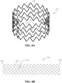
- Figure 8A illustrates the stent spring 120 in the rolled configuration, according to a further aspect of the present disclosure
- Figure 8B illustrates the stent spring 120 of Figure 8A in the unrolled configuration.
- the openings 142 can substantially define a chevron pattern.
- Figure 9A illustrates the stent spring 120 in the rolled configuration
- Figure 9B illustrates the stent spring 120 of Figure 9A in the unrolled configuration
- the openings 142 can substantially define an elongated hexagonal shape
- the stent spring 120 can comprise a spring steel material.
- Example aspects can be coated with a rubber or liquid metal material, zinc-nickel material, phosphate, electrophoretic paint (e-coating), polyester, or fusion-bonded epoxy (FBE), as described above.
- the stent spring 120 can comprise a stainless steel material, or any other suitable spring material.
- Figure 10 illustrates still another aspect of the stent spring 120 the rolled configuration.
- the openings 142 can substantially define an elongated hexagonal shape.
- the stent spring 120 can comprise a carbon fiber material.
- the stent spring 120 comprises the tabs 960 extending radially inward towards the void 130.
- the tabs 960 can be formed extending inward rather than having to be bent inwards, as may be required by the aspect of Figure 9A .
- Each of the tabs 960 can define one of the tab openings 962 therethrough.
- the wire can be dissolved by electricity, chemicals, water, or any other suitable dissolving mechanism.
- the compression mechanism can be a hose clamp.
- the hose clamp or other compression mechanism can comprise a worm drive.
- Figure 11 illustrates another example aspect of the stent spring 120 in the rolled configuration.
- the present stent spring 120 can comprise an inner stent spring 1122 aligned and connected with an outer stent spring 1124 to provide increased stiffness of the stent spring 120, while maintaining flexibility of the stent spring 120.
- Each of the inner stent spring 1122 and outer stent spring 1124 of the present aspect can be substantially similar in shape to the stent spring 120 illustrated in Figure 10 ; however, in other aspects, the inner and outer stent springs 1122,1124 can be differently shaped.
- the inner and outer stent springs 1122,1124 can be formed from carbon fiber, and in another example aspect, the inner and outer stent springs 1122,1124 can be formed from nylon. In other aspects, the inner and outer stent springs 1122,1124 can be formed from any suitable material, including but not limited to stainless steel, spring steel, aluminum, nitinol, cobalt chromium, POM (polyoxymethylene), and PVC (polyvinyl chloride). According to example aspects, the inner and outer stent springs can be joined together at a plurality of upper bends 1102 and lower bends 1104 thereof, as shown.
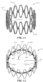
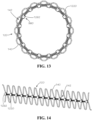
- Figures 12 and 13 illustrates an example aspect of the stent spring 120 in the rolled configuration, wherein the tabs 960 are formed as hollow cylindrical structures 1262 each defining the tab opening 962 extending therethrough.
- a coil spring 1220 can extend through the tab openings 962, as shown.
- the coil spring 1220 can define a coil spring force.
- the coil spring 1220 can be compressed in the compressed stent spring configuration and can be expanded in the expanded stent spring configuration.
- a compression force e.g. a pushing force, tension or pulling force, or any other suitable force
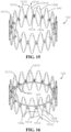
- Figures 15 and 16 illustrates an example aspect of the stent spring 120 in the rolled configuration, according to another aspect of the present disclosure.
- the stent spring 120 can be similar to the stent spring 120 illustrated Figure 10 .
- the stent spring 120 of the present aspect can further comprise a wire or wires 1510 connected to one or more of the strands 140 of the stent spring 120.
- the wires 1510 can be a plurality of Nitinol super-elastic wires 1512, which can be configured to provide added flexibility to the stent spring 120.
- Figures 18 and 19 illustrates another aspect, wherein each of the wires 1510 can be positioned on an inner periphery 1810 of the stent spring 120 proximate to an upper bend 1812 or lower bend 1814 thereof.
- the wires 1510 can be connected to the stent spring 120 by an adhesive, or other fastener, and the first and second ends 1514,1516 of the wires 1510 do not extend into the strands 140.
- the first and second ends 1514,1516 of each of the wires 1510 can engage the first and second grooves (not shown) formed in a corresponding strand 140 to connect the wire 1510 to the stent spring 120.
- Example aspects of the stent spring 120 can comprise a coating, such as, for example, a rubber coating.
- the stent spring 120 can be coated in a Plasti Dip ® coating.
- a Plasti Dip ® coating is a synthetic rubber coating that can be applied by spraying, brushing, dipping, or the like, and which can be configured to air dry.
- the Plasti Dip ® material can be non-slip, flexible, durable, and insulating material in some aspects.
- the stent spring 120 can be coated in a Flex Seal ® coating.
- the Flex Seal ® coating is a synthetic rubber coating similar to the Plasti Dip ® coating.
- the compression disc 2510 can further comprise a plurality of connectors 2620 generally received between the upper disc 2512 and lower disc 2712 and proximate to the outer side edge 2518 of the compression disc 2510.
- a head 2622 of each of the connectors 2620 can be configured to extend into a corresponding one of the disc slots 2516.
- an inner end 2662 of each of the tabs 960 can be pushed past the head 2622 of the corresponding connector 2620 and into the corresponding disc slot 2516, such that the head 2622 of each connector 2620 extends through the tab opening 962 (shown in Figure 9A ) of the corresponding tab 960.
- a stent spring for repairing a pipe can comprise a substantially tubular mesh structure defining a void, the void can define a central axis, the mesh structure can comprise one or more strands, and the one or more strands can define a plurality of openings.
- the stent spring can be configurable in an expanded stent spring configuration and a compressed stent spring configuration.
- the stent spring can further comprise a tab extending radially inward from the mesh structure into the void, and the tab can define a tab opening.
- the stent spring can comprise an inner stent spring connected to an outer stent spring, the inner stent spring can comprise the mesh structure and the tab, and the outer stent spring can be configured to increase a stiffness of the inner stent spring.
- the elastic wire can define a first end and a second end, the first end of the elastic wire can engage a first one of the strands, and the second end of the elastic wire can engage a second one of the strands.
- the first one of the strands can define a first groove
- the second one of the strands can define a second groove
- the first end can be received within the first groove
- the second end can be received within the second groove.
- the elastic wire can define a middle section between the first end and second end, and at least a portion of the middle section can be exposed.
- the elastic wire can be positioned on an inner periphery of the stent spring.
- a method for retaining a stent in a compressed configuration can comprise providing a stent, wherein the stent can comprise a stent spring, a seal, and a tab extending radially inward from the stent spring.
- the method can further comprise biasing the stent to a compressed configuration and engaging the tab with a compression mechanism to retain the stent in the compressed configuration.
- a stent in another exemplary aspect, can comprise a stent spring and a seal wrapped around a circumference of the stent spring, the stent spring can define a substantially tubular mesh structure, the stent can be configurable in an expanded configuration and a compressed configuration, and the stent spring can bias the stent to the expanded configuration.
Landscapes
- Engineering & Computer Science (AREA)
- General Engineering & Computer Science (AREA)
- Mechanical Engineering (AREA)
- Media Introduction/Drainage Providing Device (AREA)
Abstract
Description
- This disclosure relates to the field of pipe repair. More specifically, this disclosure relates to stent springs and stents for repairing a pipe.
- Piping systems, including municipal water systems, can develop breaks in pipe walls that can cause leaking. Example of breaks in a pipe wall can include radial cracks, axial cracks, point cracks, etc. Repairing a break in a pipe wall often requires the piping system to be shut off, which can be inconvenient for customers and costly for providers. Further, repairs can necessitate grandiose construction, including the digging up of streets, sidewalks, and the like, which can be costly and time-consuming.
- It is to be understood that this summary is not an extensive overview of the disclosure. This summary is exemplary and not restrictive, and it is intended neither to identify key or critical elements of the disclosure nor delineate the scope thereof. The sole purpose of this summary is to explain and exemplify certain concepts off the disclosure as an introduction to the following complete and extensive detailed description.
- Disclosed in a stent spring for repairing a pipe can comprising a substantially tubular mesh structure defining a void, the void defining a central axis, the mesh structure comprising one or more strands, the one or more strands defining a plurality of openings, wherein the stent spring is configurable in an expanded stent spring configuration and a compressed stent spring configuration; and a tab extending radially inward from the mesh structure into the void, the tab defining a tab opening.
- Also disclosed is a stent spring for repairing a pipe comprising a substantially tubular mesh structure comprising one or more strands, the one or more strands comprising a spring material, wherein the stent spring is expandable and compressible between an expanded stent spring configuration and a compressed stent spring configuration; and an elastic wire connected to the one or more strands, the elastic wire configured to increase a flexibility of the stent spring.
- A method for retaining a stent in a compressed configuration is also disclosed, the method comprising providing a stent, the stent comprising a stent spring, a seal, and a tab extending radially inward from the stent spring; biasing the stent to a compressed configuration; and engaging the tab with a compression mechanism to retain the stent in the compressed configuration.
- A stent is also disclosed, the stent comprising a stent spring defining a substantially tubular mesh structure; and a seal wrapped around a circumference of the stent spring, wherein the stent is configurable in an expanded configuration and a compressed configuration and the stent spring biases the stent to the expanded configuration
- Various implementations described in the present disclosure may include additional systems, methods, features, and advantages, which may not necessarily be expressly disclosed herein but will be apparent to one of ordinary skill in the art upon examination of the following detailed description and accompanying drawings. It is intended that all such systems, methods, features, and advantages be included within the present disclosure and protected by the accompanying claims.
- The features and components of the following figures are illustrated to emphasize the general principles of the present disclosure. Corresponding features and components throughout the figures may be designated by matching reference characters for the sake of consistency and clarity.
-
FIG. 1A is a top perspective view of a stent, in accordance with one aspect of the present disclosure, comprising a stent spring and a seal. -
FIG. 1B is a top perspective view of the stent spring ofFIG. 1A . -
FIG. 2 is a top perspective view of the stent spring, in accordance with another aspect of the present disclosure. -
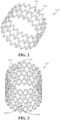
FIG. 3 is a top perspective view of the stent spring, in accordance with another aspect of the present disclosure. -
FIG. 4A is a perspective view of the stent spring, in accordance with another aspect of the present disclosure, wherein the stent spring is in a rolled configuration. -
FIG. 4B is perspective view of the stent spring ofFIG. 4A , wherein the stent spring is in an unrolled configuration. -
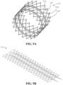
FIG. 5A is a bottom perspective view of the stent spring, in accordance with another aspect of the present disclosure, in the rolled configuration. -
FIG. 5B is perspective view of the stent spring ofFIG. 5A in the unrolled configuration. -
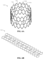
FIG. 6A is a top perspective view of the stent spring, in accordance with another aspect of the present disclosure, in the rolled configuration. -
FIG. 6B is perspective view of the stent spring ofFIG. 6A in the unrolled configuration. -
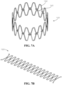
FIG. 7A is a top perspective view of the stent spring, in accordance with another aspect of the present disclosure, in the rolled configuration. -
FIG. 7B is perspective view of the stent spring ofFIG. 7A in the unrolled configuration. -
FIG. 8A is a top perspective view of the stent spring, in accordance with another aspect of the present disclosure, in the rolled configuration. -
FIG. 8B is front view of the stent spring ofFIG. 8A in the unrolled configuration. -
FIG. 9A is a top perspective view of the stent spring, in accordance with another aspect of the present disclosure, in the rolled configuration. -
FIG. 9B is perspective view of the stent spring ofFIG. 9A in the unrolled configuration. -
FIG. 10 is a top perspective view of the stent spring, in accordance with another aspect of the present disclosure. -
FIG. 11 is a top perspective view of the stent spring, according to another aspect of the present disclosure. -
FIG. 12 is a top perspective view of the stent spring in the rolled configuration, according to another aspect of the present disclosure. -
FIG. 13 is a top view of the stent spring ofFIG. 12 . -
FIG. 14 is a perspective view of the stent spring ofFIG. 12 in the unrolled configuration. -
FIG. 15 is a top perspective view of the stent spring, according to another aspect of the present disclosure, wherein the stent spring comprises elastic wires. -
FIG. 16 is a top perspective view of the stent spring ofFIG. 15 further comprising a connecting band. -
FIG. 17 is a top perspective view of another aspect of the stent spring comprising the elastic wires. -
FIG. 18 is a top perspective view of another aspect of the stent spring comprising the elastic wires. -
FIG. 19 is a top perspective view of the stent spring ofFIG. 18 . -
FIG. 20 is a front view of the stent spring comprising a rubber coating according to another aspect of the present disclosure. -
FIG. 21 is a perspective view of the stent spring comprising the rubber coating according to another aspect of the present disclosure. -
FIG. 22 is a top perspective view of the stent spring ofFIG. 20 without the rubber coating. -
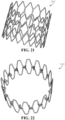
FIG. 23 is a top perspective view of the stent spring in accordance to another aspect of the present disclosure. -
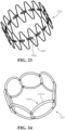
FIG. 24 is a top perspective of another aspect of the stent spring, according to another aspect of the present disclosure. -
FIG. 25 is a top view of the stent spring retained in a compressed stent spring configuration by a compression mechanism. -
FIG. 26 is a detail view of the stent spring ofFIG. 25 retained in the compressed stent spring configuration by the compression mechanism ofFIG. 25 . -
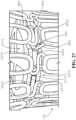
FIG. 27 is another detail view of the stent spring ofFIG. 25 retained in the compressed stent spring configuration by the compression mechanism ofFIG. 25 . -
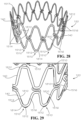
FIG. 28 is a top perspective view of the stent spring comprising the elastic wires, according to another aspect of the present disclosure. -
FIG. 29 is a detail view of the stent spring ofFIG. 28 . -
FIG. 30 is a top perspective view of the stent spring ofFIG. 18 further comprising the rubber coating. -
FIG. 31 is a detail view of the stent spring ofFIG. 30 . - The present disclosure can be understood more readily by reference to the following detailed description, examples, drawings, and claims, and the previous and following description. However, before the present devices, systems, and/or methods are disclosed and described, it is to be understood that this disclosure is not limited to the specific devices, systems, and/or methods disclosed unless otherwise specified, and, as such, can, of course, vary. It is also to be understood that the terminology used herein is for the purpose of describing particular aspects only and is not intended to be limiting.
- The following description is provided as an enabling teaching of the present devices, systems, and/or methods in its best, currently known aspect. To this end, those skilled in the relevant art will recognize and appreciate that many changes can be made to the various aspects of the present devices, systems, and/or methods described herein, while still obtaining the beneficial results of the present disclosure. It will also be apparent that some of the desired benefits of the present disclosure can be obtained by selecting some of the features of the present disclosure without utilizing other features. Accordingly, those who work in the art will recognize that many modifications and adaptations to the present disclosure are possible and can even be desirable in certain circumstances and are a part of the present disclosure. Thus, the following description is provided as illustrative of the principles of the present disclosure and not in limitation thereof.
- As used throughout, the singular forms "a," "an" and "the" include plural referents unless the context clearly dictates otherwise. Thus, for example, reference to "an element" can include two or more such elements unless the context indicates otherwise.
- Ranges can be expressed herein as from "about" one particular value, and/or to "about" another particular value. When such a range is expressed, another aspect includes from the one particular value and/or to the other particular value. Similarly, when values are expressed as approximations, by use of the antecedent "about," it will be understood that the particular value forms another aspect. It will be further understood that the endpoints of each of the ranges are significant both in relation to the other endpoint, and independently of the other endpoint.
- For purposes of the current disclosure, a material property or dimension measuring about X or substantially X on a particular measurement scale measures within a range between X plus an industry-standard upper tolerance for the specified measurement and X minus an industry-standard lower tolerance for the specified measurement. Because tolerances can vary between different materials, processes and between different models, the tolerance for a particular measurement of a particular component can fall within a range of tolerances.
- As used herein, the terms "optional" or "optionally" mean that the subsequently described event or circumstance can or cannot occur, and that the description includes instances where said event or circumstance occurs and instances where it does not.
- The word "or" as used herein means any one member of a particular list and also includes any combination of members of that list. Further, one should note that conditional language, such as, among others, "can," "could," "might," or "may," unless specifically stated otherwise, or otherwise understood within the context as used, is generally intended to convey that certain aspects include, while other aspects do not include, certain features, elements and/or steps. Thus, such conditional language is not generally intended to imply that features, elements and/or steps are in any way required for one or more particular aspects or that one or more particular aspects necessarily include logic for deciding, with or without user input or prompting, whether these features, elements and/or steps are included or are to be performed in any particular aspect.
- Disclosed are components that can be used to perform the disclosed methods and systems. These and other components are disclosed herein, and it is understood that when combinations, subsets, interactions, groups, etc. of these components are disclosed that while specific reference of each various individual and collective combinations and permutation of these may not be explicitly disclosed, each is specifically contemplated and described herein, for all methods and systems. This applies to all aspects of this application including, but not limited to, steps in disclosed methods. Thus, if there are a variety of additional steps that can be performed it is understood that each of these additional steps can be performed with any specific aspect or combination of aspects of the disclosed methods.
- Disclosed in the present application is a stent for repairing a pipe, and associated methods, systems, devices, and various apparatus. Example aspects of the stent can be oriented in an expanded configuration and a compressed configuration. The stent can comprise a stent spring and a seal. Example aspects of the stent spring can define a tubular mesh structure comprising one or more strands. It would be understood by one of skill in the art that the disclosed stent is described in but a few exemplary aspects among many. No particular terminology or description should be considered limiting on the disclosure or the scope of any claims issuing therefrom.
-
Figure 1A illustrates a first aspect of astent 100 according to the present disclosure. As shown, thestent 100 can comprise astent spring 120 and aseal 170. Example aspects of thestent spring 120 can define a spring force and can be expandable and compressible, such that thestent spring 120 can be oriented in an expanded stent spring configuration, as shown inFigure 1A , and a compressed stent spring configuration, as shown inFigure 25 . As such, thestent 100 itself can also be oriented in an expanded configuration and a compressed configuration. According to example aspects, thestent 100 can be expanded within a pipe (not shown) such that theseal 170 can engage an inner wall (not shown) of the pipe where a crack or other damage is present, in order to create a watertight seal between thestent 100 and the inner wall of the pipe to prevent leaking at the damage site. - As shown in
Figure 1A , thestent spring 120 can bias thestent 100 to the expanded configuration. In the depicted aspect, thestent spring 120 can be formed as a substantially tubular mesh structure defining opposing open ends (e.g. atop end 122 and a bottom end 124). Thestent spring 120 can further define an outer surface 126 (shown inFigure 1B ) and an oppositeinner surface 128. Theinner surface 128 can define avoid 130. The void 130 can extend between the open top and bottom ends 122,124 of thestent spring 120, and can allow fluid to pass therethrough when thestent 100 is received in the pipe. Acentral axis 132 can extend substantially through a center of the void 130, as shown. According to example aspects, thestent spring 120 can be formed from a spring material. For example, thestent spring 120 can comprise a metal material, such as stainless steel, spring steel, aluminum, nitinol, cobalt chromium, or any other suitable material. In other aspects, thestent spring 120 can be formed from a plastic material, such as, for example, nylon, POM (polyoxymethylene), or PVC (polyvinyl chloride). In still another aspect, thestent spring 120 can be formed from a carbon fiber material. Optionally, the material can be an NSF certified material that can comply with various public health safety standards. For example, in some aspects, the material can be approved as safe for use in drinking-water applications. Moreover, in some aspects, thestent spring 120 can comprise a coating, such as, for example, a rubber or liquid metal coating. The coating can improve mechanical properties of thestent spring 120. For example, the coating can improve the tensile strength of thestent spring 120 by providing a flexible and/or springy outer layer. In some aspects, the coating can also be corrosion resistant, or a separate coating can be applied for corrosion resistance. For example, a corrosion resistant coating can comprise a zinc-nickel material, phosphate, electrophoretic paint (e-coating), polyester, fusion-bonded epoxy (FBE), or any other suitable corrosion resistant material. - Example aspects of the
seal 170 can be formed as a continuous, tubular sleeve structure, as shown, and can define anouter surface 172 and aninner surface 174. In the present aspect, theouter surface 172 of theseal 170 can define a stent diameter D1 of thestent 100. Example aspects of theseal 170 can comprise a flexible and compressible material, such as, for example, neoprene. In other aspects, theseal 170 can be formed from another synthetic rubber material such as EPDM rubber, natural rubber, foam, epoxy, silicone, a resin-soaked cloth, or any other suitable flexible material for providing a watertight seal between thestent 100 and the inner wall of the pipe. According to example aspects, theseal 170 can wrap around a circumference of thestent spring 120, and theinner surface 174 of theseal 170 can engage theouter surface 126 of thestent spring 120. In a particular aspect, theseal 170 can cover the entireouter surface 126 of thestent spring 120, as shown. However, in other aspects, theseal 170 can cover only a portion of theouter surface 126 of thestent spring 120. In still other aspects, theseal 170 may not wrap entirely around the circumference of thestent spring 120. In the present aspect, theseal 170 can fit snugly on thestent spring 120. In some aspects, theseal 170 can be coupled to thestent spring 120 by a fastener (not shown), such as, for example, stitching, adhesives, ties, or any other suitable fastener known in the art. - In the expanded configuration of the
stent 100, as shown inFigure 1A , the spring force of thestent spring 120 can bias thestent spring 120 and theseal 170 radially outward relative to thecentral axis 132, such that each of thestent spring 120 and seal 170 can define relatively concentric tubular shapes, as shown. In the expanded configuration, thestent 100 can define its largest possible stent diameter D1. In some aspects, in the expanded configuration, the stent diameter D1 can be slightly greater than an inner pipe diameter as defined by the inner wall of the pipe to aid in retaining thestent 100 against the inner wall. - In the compressed configuration, a compression force (i.e., a pushing force, a pulling force, or any other suitable force) can be applied to the
stent 100 by a compression mechanism to bias thestent 100, including thestent spring 120 and theseal 170, to the compressed configuration. Various example aspects of such the compression mechanism are described through the present application, including, for example, an internal compression disc 2510 (shown inFigure 25 ). The compression force can overcome the spring force, and theseal 170 andstent spring 120 can compress or fold radially inward towards the void 130 to define a smaller stent diameter D1 and a smaller overall stent volume than in the expanded configuration. The reduced stent diameter D1 and stent volume in the compressed configuration can allow for easier insertion of thestent 100 into the pipe or a pipeline (not shown) and easier navigation of thestent 100 through the pipe or pipeline. When the compression force is removed or reduced to less than the spring force, thestent spring 120 can bias thestent 100 back to the expanded configuration. -
Figure 1B illustrates thestent spring 120 ofFigure 1A with the seal 170 (shown inFigure 1A ) removed for full visibility of the of thestent spring 120. As shown, the tubular mesh structure of thestent spring 120 can comprise one ormore strands 140 arranged to define a plurality ofopenings 142 therebetween. In the present aspect, as shown, a plurality of theopenings 142a can define a substantially circular shape, whileother openings 142b can define a shape that is substantially that of a pair of conjoined diamonds. In other aspects, theopenings 142 can define any other suitable shape(s), some examples of which are described below. According to example aspects, the mesh structure of thestent spring 120 can be laser cut, chemically etched, or stamped from a sheet of material (e.g., a sheet of metal). In other aspects, the mesh structure of thestent spring 120 can be formed by stereolithography (e.g., 3D printing), or by any other suitable manufacturing method suitable for forming a mesh structure. In some example aspects, thestent spring 120 can be oriented in a rolled configuration for use, as shown, and an unrolled configuration, as shown inFigure 4B . In example aspects, thestent spring 120 can be manufactured in the unrolled configuration, and rolled into the rolled configuration thereafter for use.Figures 2 and 3 each illustrate an additional example aspect of thestent spring 120 in the rolled configuration. As shown in the aspect ofFigure 2 , some or all of theopenings 142 can substantially define an M-shape. As shown in the aspect ofFigure 3 , some of theopenings 142a can substantially define a diamond shape, and someother openings 142b can substantially define a series of conjoined diamond and half-diamond shapes. -
Figure 4A illustrates thestent spring 120 in the rolled configuration, according to another aspect of the present disclosure, andFigure 4B illustrates thestent spring 120 ofFigure 4A in the unrolled configuration. As shown inFigure 4A , some of theopenings 142a can substantially define a diamond shape, and someother openings 142b can substantially define a conjoined series of diamond and partial-diamond shapes. As shown, in the unrolled configuration, thestent spring 120 can be substantially flat and can define afirst end 450 and an opposingsecond end 452. According to example aspects, the mesh structure of thestent spring 120 can be manufactured in the unrolled configuration, for example, by laser cutting or sterolithography. Thestent spring 120 can then be rolled into the rolled configuration. To retain thestent spring 120 in the rolled configuration, thefirst end 450 of thestent spring 120 can be spot welded, riveted, or otherwise attached by any suitable attachment method, to thesecond end 452. In other aspects, thefirst end 450 of thestent spring 120 can be attached to thesecond end 452 by a fastener, such as, for example, one or more nut and bolt assemblies, adhesives, clips, snaps, ties, or any other suitable fastener or combination of fasteners know in the art. Furthermore, according to example aspects, the rolled stent spring 120 (or in other aspects, the unrolled stent spring 120) can be heat treated to harden thestent spring 120. In one example aspect, thestent spring 120 can be hardened to between about 40-45 HRC, for example and without limitationcircular. -
Figure 5A illustrates thestent spring 120 in the rolled configuration, according to another aspect of the present disclosure, andFigure 5B illustrates thestent spring 120 ofFigure 5A in the unrolled configuration. Referring toFigure 5A , in the present aspect, some of theopenings 142a can substantially define a diamond shape, and someother openings 142b can substantially define a pair of half-diamond shapes connected by an elongated rectangular shape.Figure 6A illustrates thestent spring 120 in the rolled configuration, according to yet another aspect of the present disclosure, andFigure 6B illustrates thestent spring 120 ofFigure 6A in the unrolled configuration. Referring toFigure 6A , in the present aspect, some of theopenings 142a can substantially define a diamond shape, and someother openings 142b can substantially define a series of diamond and half-diamond shapes.Figure 7A illustrates still another aspect of thestent spring 120 in the rolled configuration, andFigure 7B illustrates thestent spring 120 ofFigure 7A in the unrolled configuration. In the present aspect, theopenings 142 can substantially define an elongated hexagonal shape.Figure 8A illustrates thestent spring 120 in the rolled configuration, according to a further aspect of the present disclosure, andFigure 8B illustrates thestent spring 120 ofFigure 8A in the unrolled configuration. In the present aspect, theopenings 142 can substantially define a chevron pattern. -
Figure 9A illustrates thestent spring 120 in the rolled configuration, according to yet another aspect of the present disclosure, andFigure 9B illustrates thestent spring 120 ofFigure 9A in the unrolled configuration. In the present aspect, theopenings 142 can substantially define an elongated hexagonal shape. Furthermore, in the present aspect, thestent spring 120 can comprise a spring steel material. Example aspects can be coated with a rubber or liquid metal material, zinc-nickel material, phosphate, electrophoretic paint (e-coating), polyester, or fusion-bonded epoxy (FBE), as described above. In other aspects, thestent spring 120 can comprise a stainless steel material, or any other suitable spring material. As shown, example aspects of thestent spring 120 can comprise one ormore tabs 960, each defining atab opening 962 therethrough. Thetabs 960 can be bent inward towards thevoid 130 and the compression mechanism can engage thetabs 960 to compress thestent spring 120 to the compressed stent spring configuration. In a first example aspects, a cable (not shown), or other fastening device, can pass through the tab opening 962 of each of thetabs 960 and can be tightened to contract the stent 100 (shown inFigure 1A ) to the compressed configuration. -
Figure 10 illustrates still another aspect of thestent spring 120 the rolled configuration. In the present aspect, theopenings 142 can substantially define an elongated hexagonal shape. Furthermore, in the present aspect, thestent spring 120 can comprise a carbon fiber material. As shown, thestent spring 120 comprises thetabs 960 extending radially inward towards thevoid 130. In the present aspect, thetabs 960 can be formed extending inward rather than having to be bent inwards, as may be required by the aspect ofFigure 9A . Each of thetabs 960 can define one of thetab openings 962 therethrough. As described above, in example aspects, a cable (not shown) can pass through the tab opening 962 of each of thetabs 960 and can be tightened to contract the stent 100 (shown inFigure 1A ) to the compressed configuration through tension in the cable. The cable can be cut to release the tension force on thestent 100 and to allow thestent spring 120 to return to the expanded stent spring configuration, thus biasing thestent 100 to the expanded configuration. In other aspects, thestent 100 can be compressed by another compression or contraction mechanism, such as a compression sleeve or tube, a dissolvable wire, or any other suitable mechanisms known in the art. In an aspect comprising a dissolvable wire, the wire can be dissolved by electricity, chemicals, water, or any other suitable dissolving mechanism. In still another aspect, the compression mechanism can be a hose clamp. In some aspects, the hose clamp or other compression mechanism can comprise a worm drive. -
Figure 11 illustrates another example aspect of thestent spring 120 in the rolled configuration. As shown, thepresent stent spring 120 can comprise aninner stent spring 1122 aligned and connected with anouter stent spring 1124 to provide increased stiffness of thestent spring 120, while maintaining flexibility of thestent spring 120. Each of theinner stent spring 1122 andouter stent spring 1124 of the present aspect can be substantially similar in shape to thestent spring 120 illustrated inFigure 10 ; however, in other aspects, the inner and outer stent springs 1122,1124 can be differently shaped. In one example aspect, the inner and outer stent springs 1122,1124 can be formed from carbon fiber, and in another example aspect, the inner and outer stent springs 1122,1124 can be formed from nylon. In other aspects, the inner and outer stent springs 1122,1124 can be formed from any suitable material, including but not limited to stainless steel, spring steel, aluminum, nitinol, cobalt chromium, POM (polyoxymethylene), and PVC (polyvinyl chloride). According to example aspects, the inner and outer stent springs can be joined together at a plurality ofupper bends 1102 andlower bends 1104 thereof, as shown. -
Figures 12 and13 illustrates an example aspect of thestent spring 120 in the rolled configuration, wherein thetabs 960 are formed as hollowcylindrical structures 1262 each defining thetab opening 962 extending therethrough. In the present aspect, acoil spring 1220 can extend through thetab openings 962, as shown. Thecoil spring 1220 can define a coil spring force. In example aspects, like thestent spring 120, thecoil spring 1220 can be compressed in the compressed stent spring configuration and can be expanded in the expanded stent spring configuration. As described above, in the compressed stent spring configuration, a compression force (e.g. a pushing force, tension or pulling force, or any other suitable force) can be applied to the stent 100 (shown inFigure 1A ). The compression force can overcome the spring force of thestent spring 120 and the coil spring force of thecoil spring 1220, and thestent spring 120,coil spring 1220, and seal 170 (shown inFigure 1A ) can be compressed or folded radially inward towards thevoid 130. When compressed, thestent 100 can define a smaller stent diameter D1 (shown inFigure 1A ) and a smaller overall stent volume than in the expanded configuration. When the compression force is removed or reduced to less than the spring force and coil spring force, both of thestent spring 120 and thecoil spring 1220 can assist in biasing thestent 100 fully back to the expanded configuration. As such, in instances where one of thestent spring 120 andcoil spring 1220 may not bias thestent 100 fully back to the expanded configuration on its own, the other of thestent spring 120 andcoil spring 1220 can assist in further biasing thestent 100 towards the expanded configuration. Moreover, as shown inFigure 13 , example aspects of thestent spring 120 can be formed from a Windform® material, such as, for example, a Windform® SP material. The Windform SP material is a carbon fiber reinforced composite polyamide material, which can be durable, insulating, and water resistant.Figure 14 illustrates thestent spring 120 ofFigures 12 and13 in the unrolled configuration. -
Figures 15 and 16 illustrates an example aspect of thestent spring 120 in the rolled configuration, according to another aspect of the present disclosure. Thestent spring 120 can be similar to thestent spring 120 illustratedFigure 10 . However, as shown, thestent spring 120 of the present aspect can further comprise a wire orwires 1510 connected to one or more of thestrands 140 of thestent spring 120. In one example aspect, thewires 1510 can be a plurality of Nitinolsuper-elastic wires 1512, which can be configured to provide added flexibility to thestent spring 120. In example aspects, each of the Nitinolsuper-elastic wires 1512 can define afirst end 1514, asecond end 1516, and amiddle section 1517 extending therebetween. Thefirst end 1514 can be received within a first groove (not shown) formed within a correspondingfirst strand 140a, and thesecond end 1516 can be received within a second groove (not shown) of an adjacentsecond strand 140b. - As shown in
Figure 16 , in some aspects, the compression mechanism can be a connectingband 1610. The connectingband 1610 can engage each of thetabs 960 of thestent spring 120 to retain thestent spring 120 in the compressed stent spring configuration while thewires 1510 are assembled with thestent spring 120. Furthermore, in the present aspect, themiddle section 1517 of eachwire 1510 can be substantially exposed. However, in other aspects, thewires 1510 can be more fully received within thestrands 140 of thestent spring 120, such that a lesser portion of themiddle section 1517 is exposed, as depicted inFigure 17 , and in still other aspects, thewires 1510 can be completely received within thestrands 140.Figures 18 and19 illustrates another aspect, wherein each of thewires 1510 can be positioned on aninner periphery 1810 of thestent spring 120 proximate to anupper bend 1812 orlower bend 1814 thereof. In one aspect, thewires 1510 can be connected to thestent spring 120 by an adhesive, or other fastener, and the first andsecond ends wires 1510 do not extend into thestrands 140. However, in other aspects, the first andsecond ends wires 1510 can engage the first and second grooves (not shown) formed in acorresponding strand 140 to connect thewire 1510 to thestent spring 120. - Example aspects of the
stent spring 120 can comprise a coating, such as, for example, a rubber coating. For example, as shown in the aspect ofFigure 20 , thestent spring 120 can be coated in a Plasti Dip® coating. A Plasti Dip® coating is a synthetic rubber coating that can be applied by spraying, brushing, dipping, or the like, and which can be configured to air dry. The Plasti Dip® material can be non-slip, flexible, durable, and insulating material in some aspects. In another example aspect, as shown inFigure 21 , thestent spring 120 can be coated in a Flex Seal® coating. The Flex Seal® coating is a synthetic rubber coating similar to the Plasti Dip® coating. The Flex Seal® coating can be applied by pouring, rolling, dippy, spraying, or the like, and can be durable, flexible, insulating, and water resistant. In other aspects, the coating can be any other suitable coating known in the art. Example aspects of the coating can be flexible and can improve the flexibility of thestent spring 120. In some example aspects, the coating can also be a non-slip coating that can improve the grip of thestent spring 120 on the seal 170 (shown inFigure 1A ), the pipe (not shown), or any other component engaged by thestent spring 120.Figure 22 illustrates thestent spring 120 ofFigure 20 without the Plasti Dip® coating applied. -
Figure 23 illustrates another example aspect of thestent spring 120 that can be substantially similar to thestent spring 120 ofFigure 9A . However, in the present aspect, as shown, thetabs 960 can definelarger tab openings 962 than thetab openings 962 shown inFigure 9A . Thelarger tab openings 962 can accommodate for a larger or different compression mechanism for compressing the stent 100 (shown inFigure 1A ).Figure 24 illustrates still another example aspect of thestent spring 120, wherein thestrands 140 of thestent spring 120 can be a plurality of connected, substantially circular, resilient andflexible strands 2440, as shown. The flexibility of thestrands 140 can allow thestent spring 120 to be compressed to the compressed stent spring configuration, and the resiliency of thestrands 140 can bias thestent spring 120 from the compressed stent spring configuration to the expanded stent spring configuration. - According to example aspects, the
stent spring 120 can be compressed by the compression mechanism, as described above. For example, in a particular aspect, the compression mechanism can be aninternal compression disc 2510 as illustrated inFigure 25 . According to example aspects, thecompression disc 2510 can engage each of thetabs 960 of thestent spring 120 to pull thestent spring 120 radially inward and to retain thestent spring 120 in the compressed stent spring configuration. In the present aspect, thecompression disc 2510 can comprise anupper disc 2512 and a lower disc 2712 (shown inFigure 27 ) connected to theupper disc 2512.Disc openings 2514 can be formed in each of the upper andlower discs more disc slots 2516 can be formed at anouter side edge 2518 of thecompression disc 2510. - Referring to
Figures 26 and27 , thecompression disc 2510 can further comprise a plurality ofconnectors 2620 generally received between theupper disc 2512 andlower disc 2712 and proximate to theouter side edge 2518 of thecompression disc 2510. Ahead 2622 of each of theconnectors 2620 can be configured to extend into a corresponding one of thedisc slots 2516. To mount thestent spring 120 to thecompression disc 2510 in the compressed stent spring configuration, aninner end 2662 of each of thetabs 960 can be pushed past thehead 2622 of the correspondingconnector 2620 and into thecorresponding disc slot 2516, such that thehead 2622 of eachconnector 2620 extends through the tab opening 962 (shown inFigure 9A ) of thecorresponding tab 960. To move thestent spring 120 to the expanded stent spring configuration, thecompression disc 2510 can be slid axially relative to the central axis 132 (shown inFigure 1A ). Thetabs 960 of thestent spring 120 can be pushed past theheads 2622 of the correspondingconnectors 2620, such that each of theconnectors 2620 can be disengaged from the corresponding tab opening 962, and thecompression disc 2510 can be disengaged from thestent spring 120. With thecompression disc 2510 disengaged from thestent spring 120, the spring force of thestent spring 120 can bias the stent 100 (shown inFigure 1A ) to the expanded configuration. -
Figures 28 and 29 illustrate another aspect of thestent spring 120 comprising the wires 1510 (e.g., the Nitinol super-elastic wires 1512). Thestent spring 120 of the present aspect can be similar to thestent spring 120 ofFigure 17 , wherein thefirst end 1514 of eachwire 1510 can be received through the first groove (not shown) formed within one of thestrands 140, and thesecond end 1516 of eachwire 1510 can be received within the second groove (not shown) formed in thesame strand 140. Eachwire 1510 can be oriented proximate to one of theupper bends 1812 orlower bends 1814 of thestent spring 120, as shown. In the present aspect, the first andsecond ends wires 1510 can pass through the corresponding first and second grooves, respectively, and can abut theinner periphery 1810 of thestent spring 120 proximate to the corresponding upper orlower bend middle section 1517 can be exposed. -
Figures 30 and 31 illustrate thestent spring 120 ofFigures 18 and19 dipped in the rubber coating, such as, for example, the Plasti Dip® coating or the Flex Seal® coating, as described above with reference toFigures 20 ,21, and 22 . - In one exemplary aspect, a stent spring for repairing a pipe can comprise a substantially tubular mesh structure defining a void, the void can define a central axis, the mesh structure can comprise one or more strands, and the one or more strands can define a plurality of openings. The stent spring can be configurable in an expanded stent spring configuration and a compressed stent spring configuration. The stent spring can further comprise a tab extending radially inward from the mesh structure into the void, and the tab can define a tab opening.
- In a further exemplary aspect, the stent spring can further comprise a compression mechanism configured to engage the tab to bias the stent spring to the compressed stent spring configuration. In a further exemplary aspect, the compression mechanism can comprise a cable configured to extend through the tab opening of the tab. In a further exemplary aspect, the compression mechanism can comprise a compression disc, wherein the compression disc can define a disc slot formed in an outer side edge of the compression disc, and a connector, wherein the connector can comprise a head and the head can extend into the disc slot. In a further exemplary aspect, the tab can extend into the disc slot, and the head can extend through the tab opening. In a further exemplary aspect, the stent spring can further comprise one or more elastic wires connected to the one or more strands, wherein the one or more elastic wires can be configured to increase a flexibility of the stent spring. In a further exemplary aspect, the stent spring can further comprise a coil spring extending through the tab opening, wherein the coil spring can be configured to assist in biasing the stent spring to the expanded stent spring configuration. In a further exemplary aspect, the stent spring can further comprise a flexible coating on the one or more strands, wherein the flexible coating can comprise a synthetic rubber material. In a further exemplary aspect, the stent spring can comprise an inner stent spring connected to an outer stent spring, the inner stent spring can comprise the mesh structure and the tab, and the outer stent spring can be configured to increase a stiffness of the inner stent spring.
- In another exemplary aspect, a stent spring for repairing a pipe can comprise a substantially tubular mesh structure comprising one or more strands, and the one or more strands can comprise a spring material. The stent spring can be expandable and compressible between an expanded stent spring configuration and a compressed stent spring configuration. The stent spring can further comprising an elastic wire connected to the one or more strands, wherein the elastic wire can be configured to increase a flexibility of the stent spring.
- In a further exemplary aspect, the elastic wire can define a first end and a second end, the first end of the elastic wire can engage a first one of the strands, and the second end of the elastic wire can engage a second one of the strands. In a further exemplary aspect, the first one of the strands can define a first groove, the second one of the strands can define a second groove, the first end can be received within the first groove, and the second end can be received within the second groove. In a further exemplary aspect, the elastic wire can define a middle section between the first end and second end, and at least a portion of the middle section can be exposed. In a further exemplary aspect, the elastic wire can be positioned on an inner periphery of the stent spring. In a further exemplary aspect, the one or more strands can define at least one of an upper bend and a lower bend, and the elastic wire can be positioned proximate to the at least one of an upper bend and a lower bend. In a further exemplary aspect, a first end of the elastic wire can extend through a first groove of the mesh structure and abut an inner periphery of the stent spring, a second end of the elastic wire can extend through a second groove of the mesh structure and abut an inner periphery of the stent spring, and a middle section of the elastic wire can be exposed. In a further exemplary aspect, the one or more strands can define a plurality of openings. In a further exemplary aspect, the stent spring can further comprise a tab extending radially inward from the mesh structure and a compression mechanism engaging the tab to retain the stent spring in the compressed stent spring configuration.
- In another exemplary aspect, a method for retaining a stent in a compressed configuration can comprise providing a stent, wherein the stent can comprise a stent spring, a seal, and a tab extending radially inward from the stent spring. The method can further comprise biasing the stent to a compressed configuration and engaging the tab with a compression mechanism to retain the stent in the compressed configuration.
- In a further exemplary aspect, engaging the tab with a compression mechanism can comprise inserting the tab into a disc slot of the compression mechanism and engaging a tab opening of the tab with a connector of the compression mechanism.
- In another exemplary aspect, a stent can comprise a stent spring and a seal wrapped around a circumference of the stent spring, the stent spring can define a substantially tubular mesh structure, the stent can be configurable in an expanded configuration and a compressed configuration, and the stent spring can bias the stent to the expanded configuration.
- One should note that conditional language, such as, among others, "can," "could," "might," or "may," unless specifically stated otherwise, or otherwise understood within the context as used, is generally intended to convey that certain embodiments include, while other embodiments do not include, certain features, elements and/or steps. Thus, such conditional language is not generally intended to imply that features, elements and/or steps are in any way required for one or more particular embodiments or that one or more particular embodiments necessarily include logic for deciding, with or without user input or prompting, whether these features, elements and/or steps are included or are to be performed in any particular embodiment.
- It should be emphasized that the above-described embodiments are merely possible examples of implementations, merely set forth for a clear understanding of the principles of the present disclosure. Any process descriptions or blocks in flow diagrams should be understood as representing modules, segments, or portions of code which include one or more executable instructions for implementing specific logical functions or steps in the process, and alternate implementations are included in which functions may not be included or executed at all, may be executed out of order from that shown or discussed, including substantially concurrently or in reverse order, depending on the functionality involved, as would be understood by those reasonably skilled in the art of the present disclosure. Many variations and modifications may be made to the above-described embodiment(s) without departing substantially from the spirit and principles of the present disclosure. Further, the scope of the present disclosure is intended to cover any and all combinations and subcombinations of all elements, features, and aspects discussed above. All such modifications and variations are intended to be included herein within the scope of the present disclosure, and all possible claims to individual aspects or combinations of elements or steps are intended to be supported by the present disclosure.
Claims (12)
- A stent spring for repairing a pipe comprising:a substantially tubular mesh structure defining a void, the void defining a central axis, the mesh structure comprising one or more strands, the one or more strands defining a plurality of openings, wherein the stent spring is configurable in an expanded stent spring configuration and a compressed stent spring configuration; anda tab extending radially inward from the mesh structure into the void, the tab defining a tab opening; anda flexible coating on the one or more strands, the flexible coating comprising a synthetic rubber material.
- The stent spring according to claim 1, wherein the flexible coating is a non-slip coating.
- The stent spring according to claim 1 or claim 2, further comprising a compression mechanism configured to engage the tab to bias the stent spring to the compressed stent spring configuration.
- The stent spring according to any of claims 1 to 3, further comprising an elastic wire connected to the one or more strands, the elastic wire configured to increase a flexibility of the stent spring.
- The stent spring according to claim 4, wherein;the elastic wire defines a first end and a second end;the first end of the elastic wire engages a first one of the strands; andthe second end of the elastic wire engages a second one of the strands.
- The stent spring according to claim 4 or claim 5, wherein:the first one of the strands defines a first groove;the second one of the strands defines a second groove;the first end is received within the first groove; andthe second end is received within the second groove.
- The stent spring according to claim 5, wherein the elastic wire defines a middle section between the first end and second end, and at least a portion of the middle section is exposed.
- The stent spring according to any of claims 4 to 7, wherein the elastic wire is positioned on an inner periphery of the stent spring.
- The stent spring according to any of claims 4 to 8, wherein:the one or more strands define at least one of an upper bend and a lower bend; andthe elastic wire is positioned proximate to the at least one of an upper bend and a lower bend.
- The stent spring according to claim 4, wherein:a first end of the elastic wire extends through a first groove of the mesh structure and abuts an inner periphery of the stent spring;a second end of the elastic wire extends through a second groove of the mesh structure and abuts an inner periphery of the stent spring; anda middle section of the elastic wire is exposed.
- The stent spring according to any of claims 1 to 10, wherein the one or more strands define a plurality of openings.
- A stent comprising:a stent spring comprising:a substantially tubular mesh structure defining a void, the void defining a central axis, the mesh structure comprising one or more strands, the one or more strands defining a plurality of openings, wherein the stent spring is configurable in an expanded stent spring configuration and a compressed stent spring configuration; anda tab extending radially inward from the mesh structure into the void, the tab defining a tab opening; anda flexible coating on the one or more strands, the flexible coating comprising a synthetic rubber material; anda seal wrapped around a circumference of the stent spring, wherein the stent is configurable in an expanded configuration and a compressed configuration and the stent spring biases the stent to the expanded configuration.
Applications Claiming Priority (4)
| Application Number | Priority Date | Filing Date | Title |
|---|---|---|---|
| US201962807264P | 2019-02-19 | 2019-02-19 | |
| US201962834168P | 2019-04-15 | 2019-04-15 | |
| PCT/US2020/018593 WO2020172136A1 (en) | 2019-02-19 | 2020-02-18 | Stent springs and stents for repairing pipes |
| EP20758706.4A EP3928022B1 (en) | 2019-02-19 | 2020-02-18 | Stent springs and stents for repairing pipes |
Related Parent Applications (2)
| Application Number | Title | Priority Date | Filing Date |
|---|---|---|---|
| EP20758706.4A Division-Into EP3928022B1 (en) | 2019-02-19 | 2020-02-18 | Stent springs and stents for repairing pipes |
| EP20758706.4A Division EP3928022B1 (en) | 2019-02-19 | 2020-02-18 | Stent springs and stents for repairing pipes |
Publications (2)
| Publication Number | Publication Date |
|---|---|
| EP4537795A2 true EP4537795A2 (en) | 2025-04-16 |
| EP4537795A3 EP4537795A3 (en) | 2025-08-20 |
Family
ID=72041948
Family Applications (5)
| Application Number | Title | Priority Date | Filing Date |
|---|---|---|---|
| EP24221715.6A Pending EP4537795A3 (en) | 2019-02-19 | 2020-02-18 | Stent springs and stents for repairing pipes |
| EP24221729.7A Pending EP4512376A3 (en) | 2019-02-19 | 2020-02-18 | Stent springs and stents for repairing pipes |
| EP20758706.4A Active EP3928022B1 (en) | 2019-02-19 | 2020-02-18 | Stent springs and stents for repairing pipes |
| EP24221702.4A Pending EP4509097A3 (en) | 2019-02-19 | 2020-02-18 | Stent springs and stents for repairing pipes |
| EP22204247.5A Pending EP4148316A1 (en) | 2019-02-19 | 2020-02-18 | Stent springs and stents for repairing pipes |
Family Applications After (4)
| Application Number | Title | Priority Date | Filing Date |
|---|---|---|---|
| EP24221729.7A Pending EP4512376A3 (en) | 2019-02-19 | 2020-02-18 | Stent springs and stents for repairing pipes |
| EP20758706.4A Active EP3928022B1 (en) | 2019-02-19 | 2020-02-18 | Stent springs and stents for repairing pipes |
| EP24221702.4A Pending EP4509097A3 (en) | 2019-02-19 | 2020-02-18 | Stent springs and stents for repairing pipes |
| EP22204247.5A Pending EP4148316A1 (en) | 2019-02-19 | 2020-02-18 | Stent springs and stents for repairing pipes |
Country Status (3)
| Country | Link |
|---|---|
| US (3) | US11353154B2 (en) |
| EP (5) | EP4537795A3 (en) |
| WO (1) | WO2020172136A1 (en) |
Families Citing this family (8)
| Publication number | Priority date | Publication date | Assignee | Title |
|---|---|---|---|---|
| US10641427B2 (en) | 2018-04-03 | 2020-05-05 | Mueller International, Llc | Stents and methods for repairing pipes |
| EP4537795A3 (en) | 2019-02-19 | 2025-08-20 | Mueller International, LLC | Stent springs and stents for repairing pipes |
| US11079058B2 (en) | 2019-03-15 | 2021-08-03 | Mueller International , LLC | Stent with coiled spring |
| US11187366B2 (en) | 2019-03-15 | 2021-11-30 | Mueller International, Llc | Stent for repairing a pipe |
| US11326731B2 (en) | 2019-04-24 | 2022-05-10 | Mueller International, Llc | Pipe repair assembly |
| US11391405B2 (en) | 2019-08-09 | 2022-07-19 | Mueller International, Llc | Deployment probe for pipe repair device |
| US11802646B2 (en) | 2019-08-09 | 2023-10-31 | Mueller International, Llc | Pipe repair device |
| US20230338175A1 (en) * | 2022-04-26 | 2023-10-26 | Accumedical Beijing Ltd. | Repositionable intracranial stent with retrieval mechanism |
Family Cites Families (66)
| Publication number | Priority date | Publication date | Assignee | Title |
|---|---|---|---|---|
| US3656771A (en) | 1970-12-11 | 1972-04-18 | Irrigation Accessories Co | Flexible seal assembly for spigot and bell conduit joint |
| US3895652A (en) | 1974-01-11 | 1975-07-22 | Roger G Zach | Diametrically expansible coil spring conduit plug |
| US4426095A (en) | 1981-09-28 | 1984-01-17 | Concrete Pipe & Products Corp. | Flexible seal |
| US4589447A (en) | 1983-08-03 | 1986-05-20 | Owens-Corning Fiberglas Corporation | Method of depositing a membrane within a conduit |
| EP0159300A1 (en) | 1984-03-30 | 1985-10-23 | Stig Westman | Repair sleeve for piping |
| DE3610626A1 (en) | 1986-03-29 | 1987-10-08 | Norske Stats Oljeselskap | DEVICE FOR GENERATING FORCES RADIAL ON A CYLINDRICAL SURFACE, IN PARTICULAR EMPLOYEES OR HOLDING FORCES |
| US5119862A (en) | 1988-10-31 | 1992-06-09 | Link-Pipe Technlogies, Inc. | Conduit repair apparatus |
| US4927189A (en) | 1989-04-10 | 1990-05-22 | Burkit John W | Internal expansion coupling device |
| CA2022301C (en) | 1989-08-14 | 1996-08-06 | Takayuki Kawafuji | Liner for pipeline repair and method for repairing pipelines |
| US5351720A (en) | 1992-03-10 | 1994-10-04 | Link-Pipe, Inc. | Apparatus for repairing conduits |
| EP0639958A1 (en) * | 1992-05-08 | 1995-03-01 | Schneider (Usa) Inc. | Esophageal stent and delivery tool |
| ATE164056T1 (en) | 1993-04-23 | 1998-04-15 | Schneider Europ Ag | STENT HAVING A COATING OF ELASTIC MATERIAL AND METHOD FOR APPLYING THE COATING TO THE STENT |
| CA2192520A1 (en) * | 1996-03-05 | 1997-09-05 | Ian M. Penn | Expandable stent and method for delivery of same |
| US5624124A (en) | 1996-07-15 | 1997-04-29 | Fmc Corporation | Bore seal assembly with wear ring having curvilinear spring support surface |
| WO1998020810A1 (en) * | 1996-11-12 | 1998-05-22 | Medtronic, Inc. | Flexible, radially expansible luminal prostheses |
| DK174814B1 (en) | 1998-02-25 | 2003-12-01 | Cook William Europ | stent device |
| US6200336B1 (en) | 1998-06-02 | 2001-03-13 | Cook Incorporated | Multiple-sided intraluminal medical device |
| US6820653B1 (en) | 1999-04-12 | 2004-11-23 | Carnegie Mellon University | Pipe inspection and repair system |
| DE60127530T2 (en) | 2000-02-03 | 2007-12-13 | Cook Inc., Bloomington | IMPLANTABLE VASCULAR DEVICE |
| US7267141B1 (en) * | 2000-06-05 | 2007-09-11 | Milliken & Company | Method of on-site production of novel textile reinforced thermoplastic or thermoset pipes |
| WO2001096092A1 (en) | 2000-06-09 | 2001-12-20 | Fiberliner Networks | Method and apparatus for lining a conduit |
| NO335594B1 (en) | 2001-01-16 | 2015-01-12 | Halliburton Energy Serv Inc | Expandable devices and methods thereof |
| US6648071B2 (en) * | 2001-01-24 | 2003-11-18 | Schlumberger Technology Corporation | Apparatus comprising expandable bistable tubulars and methods for their use in wellbores |
| US6712556B2 (en) | 2001-05-18 | 2004-03-30 | G. Gregory Penza | Method and apparatus for routing cable in existing pipelines |
| EP1399200B2 (en) | 2001-06-11 | 2014-07-02 | Boston Scientific Limited | COMPOSITE ePTFE/TEXTILE PROSTHESIS |
| US8488290B2 (en) | 2001-06-15 | 2013-07-16 | George M. Kauffman | Protective device |
| US7097658B2 (en) | 2001-08-22 | 2006-08-29 | Hasan Semih Oktay | Flexible MEMS actuated controlled expansion stent |
| ATE310559T1 (en) | 2002-05-29 | 2005-12-15 | Cook William A Australia | TRIGGER WIRE SYSTEM FOR A PROSTHESIS PLACEMENT DEVICE |
| US7611528B2 (en) | 2003-01-24 | 2009-11-03 | Medtronic Vascular, Inc. | Stent-graft delivery system |
| US7776078B2 (en) | 2003-05-22 | 2010-08-17 | Boston Scientfic Scimed, Inc. | Catheter balloon with improved retention |
| DE10357061B4 (en) * | 2003-12-04 | 2005-09-08 | Tracto-Technik Gmbh | Cutting system, apparatus and method for cutting pipes |
| US20050212220A1 (en) | 2004-03-26 | 2005-09-29 | Stamped Fittings, Inc. | Gasket for duct, pipe and tube joints |
| JP2005278993A (en) | 2004-03-30 | 2005-10-13 | Terumo Corp | Stent for indwelling in living body, and production method of the same |
| KR100732864B1 (en) * | 2005-08-10 | 2007-06-27 | 이철민 | Non excavation pipeline repair mesh wire installation method |
| JP5109195B2 (en) * | 2006-11-30 | 2012-12-26 | クック・メディカル・テクノロジーズ・リミテッド・ライアビリティ・カンパニー | Implant release mechanism |
| US7896915B2 (en) | 2007-04-13 | 2011-03-01 | Jenavalve Technology, Inc. | Medical device for treating a heart valve insufficiency |
| US20090171448A1 (en) * | 2007-04-27 | 2009-07-02 | Uri Eli | Implantable device with miniature rotating portion for energy harvesting |
| US7806919B2 (en) * | 2008-04-01 | 2010-10-05 | Medtronic Vascular, Inc. | Double-walled stent system |
| US8652202B2 (en) | 2008-08-22 | 2014-02-18 | Edwards Lifesciences Corporation | Prosthetic heart valve and delivery apparatus |
| US9052051B2 (en) | 2009-04-20 | 2015-06-09 | Link-Pipe, Inc. | Apparatus and method for internal repair of conduits |
| GB0911579D0 (en) | 2009-07-03 | 2009-08-12 | Brinker Technology Ltd | Apparatus and methods for maintenance and repair of vessels |
| US9326870B2 (en) * | 2010-04-23 | 2016-05-03 | Medtronic Vascular, Inc. | Biodegradable stent having non-biodegradable end portions and mechanisms for increased stent hoop strength |
| US9867725B2 (en) * | 2010-12-13 | 2018-01-16 | Microvention, Inc. | Stent |
| EP2579810A4 (en) * | 2011-02-03 | 2014-07-30 | Endospan Ltd | Implantable medical devices constructed of shape memory material |
| US8783297B2 (en) | 2011-04-27 | 2014-07-22 | Massachusetts Institute Of Technology | Robotic system for pipeline rehabilitation |
| US20130018450A1 (en) | 2011-07-13 | 2013-01-17 | Hunt James B | Prosthesis delivery system with retention sleeve |
| US9278018B2 (en) * | 2011-12-14 | 2016-03-08 | Cook Medical Technologies Llc | Circumferential trigger wire for deploying an endoluminal prosthesis |
| US20130248042A1 (en) | 2012-03-23 | 2013-09-26 | Altran Solutions Corp. | Methods and apparatuses for repairing a conduit |
| WO2014204807A1 (en) * | 2013-06-19 | 2014-12-24 | Aga Medical Corporation | Collapsible valve having paravalvular leak protection |
| US20160238178A1 (en) | 2013-10-29 | 2016-08-18 | Jeffrey M. Urbanski | Apparatus For Repairing A Pipe |
| US10111741B2 (en) | 2014-10-29 | 2018-10-30 | W. L. Gore & Associates, Inc. | Intralumenal stent graft fixation |
| US9433520B2 (en) | 2015-01-29 | 2016-09-06 | Intact Vascular, Inc. | Delivery device and method of delivery |
| EP3294221B1 (en) | 2015-05-14 | 2024-03-06 | Cephea Valve Technologies, Inc. | Replacement mitral valves |
| US10265169B2 (en) | 2015-11-23 | 2019-04-23 | Edwards Lifesciences Corporation | Apparatus for controlled heart valve delivery |
| EP4424341A3 (en) | 2016-04-25 | 2024-11-20 | Solinas Medical, Inc. | Self-sealing tubular grafts, patches, and methods for making and using them |
| DE102016006561B4 (en) | 2016-05-25 | 2022-07-28 | Uhrig Kanaltechnik Gmbh | Sealing sleeve for pipe offsets |
| CA3051272C (en) | 2017-01-23 | 2023-08-22 | Cephea Valve Technologies, Inc. | Replacement mitral valves |
| US10627038B2 (en) | 2017-09-26 | 2020-04-21 | Mueller International, Llc | Devices and methods for repairing pipes |
| DE202018100823U1 (en) | 2018-02-15 | 2018-05-16 | Hans Bohnet | Gasket for insertion into a piping system |
| US10641427B2 (en) | 2018-04-03 | 2020-05-05 | Mueller International, Llc | Stents and methods for repairing pipes |
| EP4537795A3 (en) | 2019-02-19 | 2025-08-20 | Mueller International, LLC | Stent springs and stents for repairing pipes |
| US11187366B2 (en) | 2019-03-15 | 2021-11-30 | Mueller International, Llc | Stent for repairing a pipe |
| US11079058B2 (en) | 2019-03-15 | 2021-08-03 | Mueller International , LLC | Stent with coiled spring |
| US11326731B2 (en) | 2019-04-24 | 2022-05-10 | Mueller International, Llc | Pipe repair assembly |
| US11391405B2 (en) | 2019-08-09 | 2022-07-19 | Mueller International, Llc | Deployment probe for pipe repair device |
| US11802646B2 (en) | 2019-08-09 | 2023-10-31 | Mueller International, Llc | Pipe repair device |
-
2020
- 2020-02-18 EP EP24221715.6A patent/EP4537795A3/en active Pending
- 2020-02-18 WO PCT/US2020/018593 patent/WO2020172136A1/en not_active Ceased
- 2020-02-18 EP EP24221729.7A patent/EP4512376A3/en active Pending
- 2020-02-18 EP EP20758706.4A patent/EP3928022B1/en active Active
- 2020-02-18 EP EP24221702.4A patent/EP4509097A3/en active Pending
- 2020-02-18 US US16/792,984 patent/US11353154B2/en active Active
- 2020-02-18 EP EP22204247.5A patent/EP4148316A1/en active Pending
-
2022
- 2022-04-22 US US17/727,574 patent/US11781697B2/en active Active
-
2023
- 2023-08-25 US US18/237,948 patent/US20230408018A1/en active Pending
Also Published As
| Publication number | Publication date |
|---|---|
| US20220243854A1 (en) | 2022-08-04 |
| US20230408018A1 (en) | 2023-12-21 |
| EP3928022B1 (en) | 2025-01-29 |
| US11781697B2 (en) | 2023-10-10 |
| EP4509097A2 (en) | 2025-02-19 |
| EP3928022A4 (en) | 2022-12-14 |
| EP4512376A3 (en) | 2025-06-04 |
| EP4537795A3 (en) | 2025-08-20 |
| EP4509097A3 (en) | 2025-08-20 |
| EP4512376A2 (en) | 2025-02-26 |
| WO2020172136A1 (en) | 2020-08-27 |
| US11353154B2 (en) | 2022-06-07 |
| EP4148316A1 (en) | 2023-03-15 |
| EP3928022A1 (en) | 2021-12-29 |
| US20200263823A1 (en) | 2020-08-20 |
Similar Documents
| Publication | Publication Date | Title |
|---|---|---|
| US11781697B2 (en) | Stent springs and stents for repairing pipes | |
| US12305788B2 (en) | Stent spring for pipe repair device | |
| US10641427B2 (en) | Stents and methods for repairing pipes | |
| US11480286B2 (en) | Stent for repairing a pipe | |
| US11079058B2 (en) | Stent with coiled spring | |
| US6022054A (en) | Thin wall fiberglass pipe connectors | |
| US11326731B2 (en) | Pipe repair assembly | |
| EP1877692B1 (en) | Combination of a pipe and a flexible liner assembly for repairing or reinforcing the pipe | |
| US20250102098A1 (en) | Pipe repair stent with friction elements | |
| US8668231B1 (en) | Pipe repair coupling |
Legal Events
| Date | Code | Title | Description |
|---|---|---|---|
| PUAI | Public reference made under article 153(3) epc to a published international application that has entered the european phase |
Free format text: ORIGINAL CODE: 0009012 |
|
| STAA | Information on the status of an ep patent application or granted ep patent |
Free format text: STATUS: THE APPLICATION HAS BEEN PUBLISHED |
|
| AC | Divisional application: reference to earlier application |
Ref document number: 3928022 Country of ref document: EP Kind code of ref document: P |
|
| AK | Designated contracting states |
Kind code of ref document: A2 Designated state(s): AL AT BE BG CH CY CZ DE DK EE ES FI FR GB GR HR HU IE IS IT LI LT LU LV MC MK MT NL NO PL PT RO RS SE SI SK SM TR |
|
| P01 | Opt-out of the competence of the unified patent court (upc) registered |
Free format text: CASE NUMBER: APP_24734/2025 Effective date: 20250523 |
|
| REG | Reference to a national code |
Ref country code: DE Ref legal event code: R079 Free format text: PREVIOUS MAIN CLASS: A61F0002915000 Ipc: F16L0055163000 |
|
| PUAL | Search report despatched |
Free format text: ORIGINAL CODE: 0009013 |
|
| AK | Designated contracting states |
Kind code of ref document: A3 Designated state(s): AL AT BE BG CH CY CZ DE DK EE ES FI FR GB GR HR HU IE IS IT LI LT LU LV MC MK MT NL NO PL PT RO RS SE SI SK SM TR |
|
| RIC1 | Information provided on ipc code assigned before grant |
Ipc: F16L 55/163 20060101AFI20250717BHEP Ipc: A61F 2/82 20130101ALI20250717BHEP Ipc: A61F 2/90 20130101ALI20250717BHEP Ipc: F16L 55/18 20060101ALI20250717BHEP Ipc: F16L 57/02 20060101ALI20250717BHEP Ipc: A61F 2/915 20130101ALI20250717BHEP |