EP4534775A1 - Belüftetes fassadenbefestigungssystem - Google Patents
Belüftetes fassadenbefestigungssystem Download PDFInfo
- Publication number
- EP4534775A1 EP4534775A1 EP23201320.1A EP23201320A EP4534775A1 EP 4534775 A1 EP4534775 A1 EP 4534775A1 EP 23201320 A EP23201320 A EP 23201320A EP 4534775 A1 EP4534775 A1 EP 4534775A1
- Authority
- EP
- European Patent Office
- Prior art keywords
- plate
- bracket
- insulation
- support wall
- lobes
- Prior art date
- Legal status (The legal status is an assumption and is not a legal conclusion. Google has not performed a legal analysis and makes no representation as to the accuracy of the status listed.)
- Pending
Links
Images

Classifications
-
- E—FIXED CONSTRUCTIONS
- E04—BUILDING
- E04F—FINISHING WORK ON BUILDINGS, e.g. STAIRS, FLOORS
- E04F13/00—Coverings or linings, e.g. for walls or ceilings
- E04F13/07—Coverings or linings, e.g. for walls or ceilings composed of covering or lining elements; Sub-structures therefor; Fastening means therefor
- E04F13/08—Coverings or linings, e.g. for walls or ceilings composed of covering or lining elements; Sub-structures therefor; Fastening means therefor composed of a plurality of similar covering or lining elements
- E04F13/0801—Separate fastening elements
- E04F13/0803—Separate fastening elements with load-supporting elongated furring elements between wall and covering elements
- E04F13/0805—Separate fastening elements with load-supporting elongated furring elements between wall and covering elements with additional fastening elements between furring elements and the wall
- E04F13/0807—Separate fastening elements with load-supporting elongated furring elements between wall and covering elements with additional fastening elements between furring elements and the wall adjustable perpendicular to the wall
-
- E—FIXED CONSTRUCTIONS
- E04—BUILDING
- E04F—FINISHING WORK ON BUILDINGS, e.g. STAIRS, FLOORS
- E04F13/00—Coverings or linings, e.g. for walls or ceilings
- E04F13/07—Coverings or linings, e.g. for walls or ceilings composed of covering or lining elements; Sub-structures therefor; Fastening means therefor
- E04F13/08—Coverings or linings, e.g. for walls or ceilings composed of covering or lining elements; Sub-structures therefor; Fastening means therefor composed of a plurality of similar covering or lining elements
- E04F13/0801—Separate fastening elements
- E04F13/0832—Separate fastening elements without load-supporting elongated furring elements between wall and covering elements
- E04F13/0853—Separate fastening elements without load-supporting elongated furring elements between wall and covering elements adjustable perpendicular to the wall
-
- E—FIXED CONSTRUCTIONS
- E04—BUILDING
- E04F—FINISHING WORK ON BUILDINGS, e.g. STAIRS, FLOORS
- E04F13/00—Coverings or linings, e.g. for walls or ceilings
- E04F13/07—Coverings or linings, e.g. for walls or ceilings composed of covering or lining elements; Sub-structures therefor; Fastening means therefor
- E04F13/08—Coverings or linings, e.g. for walls or ceilings composed of covering or lining elements; Sub-structures therefor; Fastening means therefor composed of a plurality of similar covering or lining elements
- E04F13/0801—Separate fastening elements
- E04F13/0832—Separate fastening elements without load-supporting elongated furring elements between wall and covering elements
- E04F13/086—Separate fastening elements without load-supporting elongated furring elements between wall and covering elements fixed by means of clamping action
-
- E—FIXED CONSTRUCTIONS
- E04—BUILDING
- E04F—FINISHING WORK ON BUILDINGS, e.g. STAIRS, FLOORS
- E04F13/00—Coverings or linings, e.g. for walls or ceilings
- E04F13/007—Outer coverings for walls with ventilating means
Definitions
- This invention relates in general to devices for connecting a façade wall (also called a mounted façade, hanging fagade or curtain façade) and more specifically to ventilated rainscreen façades or rainscreen façades to a support wall. It further refers to a solution for tightly attaching insulation panels to the support wall in the ventilated interspace between support wall and façade. It also refers to a holding arrangement comprising at least a bracket and an adapter plate useful for mounting such façade panels.
- the bracket again exhibits essentially an L-shape with a (short) fixing base and an (extended) horizontal arm.
- This horizontal arm again has an essentially flat, plate-like, rectangular shape and the fixing plate is arranged at a right angle to it.
- the invention also allows for creating an insulation of a building comprising two layers of insulation panels.
- the first insulation layer will be mounted as described above.
- the second layer with a plurality of insulation panels forming a second layer of insulation are being clamped between the first layer of insulation and a plurality of adapter plates.
- Those additional adapter plates are being sled on the horizontal arms of the existing mounted brackets; until the insulation panels are sandwiched between the lower side of the adapter plates and the first layer of insulation.
- the adapter plates can be secured by means of fixings to the horizontal arms of the existing brackets. As a result, the horizontal arm of the bracket serves twice as mounting point for adapter plates.
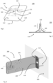
- Figure 1 shows an adapter plate 100 to be used in conjunction with a bracket 200 ( FIG. 3 , 4 ) for fixedly mounting an insulation panel 320 to a support wall 300 ( FIG. 5 +6).
- an adapter plate 100 as shown will be capable of fastening similar flat, plate-shaped objects to a support wall such as noise absorbing panels or alike.
- the adapter plate 100 exhibits an essentially flat base plate 100 with an upper side 112 and a lower side 114.
- the lower side 114 is provided to be the (later) contact surface with an insulation panel.
- From the surface of the upper side 112 there are protruding preferably (and at least) three holding / clamping structures, hereinafter designated as lobes 130, 140, 150.
- Each of the lobes has a tongue-shape with one end connected to the base plate 110 and a free end.
- the embodiment shown in Fig. 1 and Fig. 2 exhibits two sections 160, 170 for each lobe.
- a first section or spacer section 160 directly adjacent to the base plate 110 is angled under an angle ⁇ , to be chosen between 10° ⁇ ⁇ ⁇ 50°, preferably around 35°.
- the second section 170 (end section) of each lobe is again angled resulting in the end section 170 being essentially arranged in a 90° angle towards the base plate 110.
- Lengths and angles of spacer section 160 and end section 170 may be chosen differently than shown in Fig. 2 without changing the gist of the invention.
- Spacer section 160 may for example be realized as a 90° curve.
- the three lobes are arranged in such a way, that second and third lobes 140, 150 are arranged side by side but distanced from each other.
- the first lobe 130 is arranged such that it is facing, but not filling the gap between second and third lobes 140, 150.
- the result of said arrangement can be seen in Figure 2 :
- the end sections 170 of the lobes 130, 140, 150 form a guide slot 120 defined by the surfaces of the end sections 170.
- the width of that gap is chosen such it can (later) accommodate a bracket's 200 horizontal arm 220.
- angled spacer sections 160 form a funnel or guidance for the horizontal arm 220 when adapter plate 100 is properly connected to bracket 200. For that reason, any shape of spacer section 160 deviating from the described preferred embodiment shall be regarded equivalent if it serves the same purpose. However, having a funnel or guidance as described is a by far preferred embodiment, but not an essential one.
- lobes 130, 140, 150 are equipped with regular and oblong through holes allowing for fixings such as screws, rivets or alike to be set through them to connect said adapter plate 100 with a bracket 200.
- Lobe 130 exhibits a cutout 180, which has been specifically provided for allowing the clamp section 240 to pass when the adapter plate 100 is being slid onto a bracket 200.
- An adapter plate 100 can be manufactured from metal or injection molded from plastic. The applicability of material depends on the technical application and specific regulations such fire safety regulations. If made from metal, aluminium or steel are preferred. Manufacturing may use known techniques such as punching, bending, cold forming or alike.
- the shape of the adapter plate as shown is square or rectangular, but may be realized as circle, oval or of irregular shape. Since the adapter plate has also the function of a load distribution plate (when used to press an insulation panel to a support wall), dimensions of the plate, especially its effective surface, will be determined based on considerations of material savings (weight, cost) and the required holding surface. It will be designed by the man skilled in the art based on specifications and his/her experience. As an example, adapter plates between 10cm x 10cm and 13cm x 20cm have been realized with rounded corners.
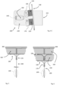
- FIG. 3 shows a so-called bracket 200, which is a load bearing part known in the art.
- the bracket 200 has an essential L-shape with a fixing base 210 and a horizontal arm 220.
- "Horizontal” in this case refers to the positioning of the arm when the bracket 200 has been properly attached to a support wall 300.
- fasteners 310 such as screws have been used to attach the bracket to such a wall.
- the bracket's horizontal arm 220 is here shown as an essentially flat rectangle with rounded corners with its base plane oriented vertically in its mounted position.
- Mounting holes 230 may be provided to allow fixings, such as a nut & bolt connection, blind rivets or alike between them and the adapter plate's mounting holes.
- the bracket's mounting holes are optional, because it may be preferred to use self-cutting and self-tapping screws.
- bracket 200 exhibits a clamp 240 with a spring-loaded tongue 250 at the free end of the horizontal arm 220.
- This clamp 240 is provided to attach a further rail-profile connecting a plurality of brackets attached to a support wall 300, thus defining a plane for the rainscreen facade.
- Said rail profile may come in variants depending on the type of façade and has therefore been omitted in the figures.
- mounting holes 230 shown in Fig. 3 is exemplary and not imperative.
- the pattern shown allows for a tilted fixture of an adapter plate 100 and is being further shown and described with respect to FIG. 4C .
- FIG. 5 and 6 are now being discussed together, exhibiting inter alia a major advantage of the design of said adapter plate 100 in combination with the bracket 200.
- Both Fig. 5 and 6 show the bracket 200 mounted to the support wall 300 as shown in Fig. 3 .
Landscapes
- Engineering & Computer Science (AREA)
- Architecture (AREA)
- Civil Engineering (AREA)
- Structural Engineering (AREA)
- Finishing Walls (AREA)
Priority Applications (1)
| Application Number | Priority Date | Filing Date | Title |
|---|---|---|---|
| EP23201320.1A EP4534775A1 (de) | 2023-10-02 | 2023-10-02 | Belüftetes fassadenbefestigungssystem |
Applications Claiming Priority (1)
| Application Number | Priority Date | Filing Date | Title |
|---|---|---|---|
| EP23201320.1A EP4534775A1 (de) | 2023-10-02 | 2023-10-02 | Belüftetes fassadenbefestigungssystem |
Publications (1)
| Publication Number | Publication Date |
|---|---|
| EP4534775A1 true EP4534775A1 (de) | 2025-04-09 |
Family
ID=88241232
Family Applications (1)
| Application Number | Title | Priority Date | Filing Date |
|---|---|---|---|
| EP23201320.1A Pending EP4534775A1 (de) | 2023-10-02 | 2023-10-02 | Belüftetes fassadenbefestigungssystem |
Country Status (1)
| Country | Link |
|---|---|
| EP (1) | EP4534775A1 (de) |
Citations (3)
| Publication number | Priority date | Publication date | Assignee | Title |
|---|---|---|---|---|
| DE1056349B (de) * | 1954-08-02 | 1959-04-30 | Eckel Oliver C | Vorrichtung zum Befestigen von Bauteilen, insbesondere Isolierplatten |
| US3019864A (en) * | 1959-10-12 | 1962-02-06 | Tempmaster Corp | Lagging mount |
| EP3783166A1 (de) * | 2019-08-20 | 2021-02-24 | Saint-Gobain Isover | Abstandsvorrichtung, die ein kit zur befestigung eines auskleidungssystems an einer auszukleidenden struktur umfasst |
-
2023
- 2023-10-02 EP EP23201320.1A patent/EP4534775A1/de active Pending
Patent Citations (3)
| Publication number | Priority date | Publication date | Assignee | Title |
|---|---|---|---|---|
| DE1056349B (de) * | 1954-08-02 | 1959-04-30 | Eckel Oliver C | Vorrichtung zum Befestigen von Bauteilen, insbesondere Isolierplatten |
| US3019864A (en) * | 1959-10-12 | 1962-02-06 | Tempmaster Corp | Lagging mount |
| EP3783166A1 (de) * | 2019-08-20 | 2021-02-24 | Saint-Gobain Isover | Abstandsvorrichtung, die ein kit zur befestigung eines auskleidungssystems an einer auszukleidenden struktur umfasst |
Similar Documents
| Publication | Publication Date | Title |
|---|---|---|
| US6128883A (en) | Brick anchor system | |
| US20060156651A1 (en) | Mounting system with threaded sliding block | |
| US10309100B2 (en) | Mullion cover hanger and curtain wall insulation system incorporating the same | |
| CA2684085C (en) | A substructure for aligning a building cover structure and an assembly bracket for use in such substructure | |
| US8844210B2 (en) | Upmount overhead brackets for office partition systems | |
| PL207375B1 (pl) | Struktura izolująca akustycznie dla budynku | |
| RU2317764C2 (ru) | Система, зажимной элемент и запирающий элемент для соединения профильных элементов | |
| EP4534775A1 (de) | Belüftetes fassadenbefestigungssystem | |
| EP0730069A1 (de) | Anordnung mit einer Platte und einem Querschnitt, sowie einem Federelement, einer Platte, einem Querschnitt und einem Formstreifen geeignet für die Anwendung in einer solchen Anordnung | |
| PL202049B1 (pl) | Zespół mocujący do mocowania okładziny do różnych elementów budowlanych, zwłaszcza do ścian budynku | |
| US11781318B2 (en) | Ceiling panel | |
| EP1764455A2 (de) | Verankerungssystem für Verkleidungsplatten und Profilen, insbesondere für hinterlüftete Fassaden | |
| JP3616614B2 (ja) | 吊りボルト支持装置 | |
| PL179060B1 (pl) | Katownik podporowy PL | |
| EP3994318B1 (de) | Profilbefestigungszubehör und stützsystem mit solch einem profilbefestigungszubehör für verkleidung, erhöhte fussböden, abgehängte decken oder dergleichen | |
| JPH0544423Y2 (de) | ||
| US12295491B2 (en) | Shelf support | |
| EP4148338B1 (de) | Kombination aus klammer und profilträger | |
| US11993490B2 (en) | Rail-fastening system | |
| JPH0544424Y2 (de) | ||
| EP1310611A1 (de) | Vorrichtung zur verstellbaren Montage eines Paneels | |
| EP3799235B1 (de) | Trägerbefestigungselement für eine elektrische installationsdose | |
| JP2862667B2 (ja) | 外壁パネルの取り付け方法及びこれに用いる外壁パネル | |
| EP1923520B1 (de) | Wandelement | |
| JP7474185B2 (ja) | 水切り仮固定治具 |
Legal Events
| Date | Code | Title | Description |
|---|---|---|---|
| PUAI | Public reference made under article 153(3) epc to a published international application that has entered the european phase |
Free format text: ORIGINAL CODE: 0009012 |
|
| STAA | Information on the status of an ep patent application or granted ep patent |
Free format text: STATUS: THE APPLICATION HAS BEEN PUBLISHED |
|
| AK | Designated contracting states |
Kind code of ref document: A1 Designated state(s): AL AT BE BG CH CY CZ DE DK EE ES FI FR GB GR HR HU IE IS IT LI LT LU LV MC ME MK MT NL NO PL PT RO RS SE SI SK SM TR |
|
| STAA | Information on the status of an ep patent application or granted ep patent |
Free format text: STATUS: REQUEST FOR EXAMINATION WAS MADE |
|
| 17P | Request for examination filed |
Effective date: 20251009 |