EP3783166A1 - Abstandsvorrichtung, die ein kit zur befestigung eines auskleidungssystems an einer auszukleidenden struktur umfasst - Google Patents
Abstandsvorrichtung, die ein kit zur befestigung eines auskleidungssystems an einer auszukleidenden struktur umfasst Download PDFInfo
- Publication number
- EP3783166A1 EP3783166A1 EP20188522.5A EP20188522A EP3783166A1 EP 3783166 A1 EP3783166 A1 EP 3783166A1 EP 20188522 A EP20188522 A EP 20188522A EP 3783166 A1 EP3783166 A1 EP 3783166A1
- Authority
- EP
- European Patent Office
- Prior art keywords
- plate
- fixing
- positioning wing
- spacer device
- positioning
- Prior art date
- Legal status (The legal status is an assumption and is not a legal conclusion. Google has not performed a legal analysis and makes no representation as to the accuracy of the status listed.)
- Pending
Links
- 238000009413 insulation Methods 0.000 claims abstract description 101
- 238000004873 anchoring Methods 0.000 claims abstract description 83
- 125000006850 spacer group Chemical group 0.000 claims description 60
- 230000000284 resting effect Effects 0.000 claims description 3
- 238000012423 maintenance Methods 0.000 claims description 2
- 238000000034 method Methods 0.000 claims description 2
- 230000002787 reinforcement Effects 0.000 description 12
- VYPSYNLAJGMNEJ-UHFFFAOYSA-N Silicium dioxide Chemical compound O=[Si]=O VYPSYNLAJGMNEJ-UHFFFAOYSA-N 0.000 description 10
- 239000000463 material Substances 0.000 description 9
- 229910052782 aluminium Inorganic materials 0.000 description 6
- XAGFODPZIPBFFR-UHFFFAOYSA-N aluminium Chemical compound [Al] XAGFODPZIPBFFR-UHFFFAOYSA-N 0.000 description 6
- 238000010276 construction Methods 0.000 description 6
- 239000011888 foil Substances 0.000 description 5
- 239000012528 membrane Substances 0.000 description 5
- 239000000377 silicon dioxide Substances 0.000 description 5
- 239000000853 adhesive Substances 0.000 description 4
- 230000001070 adhesive effect Effects 0.000 description 4
- 238000002955 isolation Methods 0.000 description 4
- 229920002994 synthetic fiber Polymers 0.000 description 4
- 230000008901 benefit Effects 0.000 description 3
- 230000000903 blocking effect Effects 0.000 description 3
- -1 polyethylene Polymers 0.000 description 3
- 239000000843 powder Substances 0.000 description 3
- 210000002105 tongue Anatomy 0.000 description 3
- 238000013519 translation Methods 0.000 description 3
- 239000002023 wood Substances 0.000 description 3
- 230000015572 biosynthetic process Effects 0.000 description 2
- 239000000470 constituent Substances 0.000 description 2
- 238000005520 cutting process Methods 0.000 description 2
- 239000002657 fibrous material Substances 0.000 description 2
- BASFCYQUMIYNBI-UHFFFAOYSA-N platinum Chemical compound [Pt] BASFCYQUMIYNBI-UHFFFAOYSA-N 0.000 description 2
- 238000009428 plumbing Methods 0.000 description 2
- 238000007789 sealing Methods 0.000 description 2
- XLYOFNOQVPJJNP-UHFFFAOYSA-N water Chemical compound O XLYOFNOQVPJJNP-UHFFFAOYSA-N 0.000 description 2
- 238000004078 waterproofing Methods 0.000 description 2
- 239000004698 Polyethylene Substances 0.000 description 1
- 239000004743 Polypropylene Substances 0.000 description 1
- 229910000831 Steel Inorganic materials 0.000 description 1
- 230000009471 action Effects 0.000 description 1
- 238000004026 adhesive bonding Methods 0.000 description 1
- 230000004888 barrier function Effects 0.000 description 1
- 239000011449 brick Substances 0.000 description 1
- 230000015556 catabolic process Effects 0.000 description 1
- 239000000919 ceramic Substances 0.000 description 1
- 239000003818 cinder Substances 0.000 description 1
- 230000000295 complement effect Effects 0.000 description 1
- 239000004035 construction material Substances 0.000 description 1
- 238000006731 degradation reaction Methods 0.000 description 1
- 230000006866 deterioration Effects 0.000 description 1
- 238000009826 distribution Methods 0.000 description 1
- 238000005553 drilling Methods 0.000 description 1
- 239000000835 fiber Substances 0.000 description 1
- 239000003365 glass fiber Substances 0.000 description 1
- 208000014674 injury Diseases 0.000 description 1
- 238000003780 insertion Methods 0.000 description 1
- 230000037431 insertion Effects 0.000 description 1
- 230000010354 integration Effects 0.000 description 1
- 230000014759 maintenance of location Effects 0.000 description 1
- 238000004519 manufacturing process Methods 0.000 description 1
- 229910052751 metal Inorganic materials 0.000 description 1
- 239000002184 metal Substances 0.000 description 1
- 238000012986 modification Methods 0.000 description 1
- 230000004048 modification Effects 0.000 description 1
- 239000004033 plastic Substances 0.000 description 1
- 229920006255 plastic film Polymers 0.000 description 1
- 229920000573 polyethylene Polymers 0.000 description 1
- 229920000139 polyethylene terephthalate Polymers 0.000 description 1
- 239000005020 polyethylene terephthalate Substances 0.000 description 1
- 229920006254 polymer film Polymers 0.000 description 1
- 229920001155 polypropylene Polymers 0.000 description 1
- 239000012254 powdered material Substances 0.000 description 1
- 230000008569 process Effects 0.000 description 1
- 230000001698 pyrogenic effect Effects 0.000 description 1
- 239000003507 refrigerant Substances 0.000 description 1
- 239000011435 rock Substances 0.000 description 1
- 239000010959 steel Substances 0.000 description 1
- 230000008733 trauma Effects 0.000 description 1
- 230000000472 traumatic effect Effects 0.000 description 1
Images


Classifications
-
- E—FIXED CONSTRUCTIONS
- E04—BUILDING
- E04F—FINISHING WORK ON BUILDINGS, e.g. STAIRS, FLOORS
- E04F13/00—Coverings or linings, e.g. for walls or ceilings
- E04F13/07—Coverings or linings, e.g. for walls or ceilings composed of covering or lining elements; Sub-structures therefor; Fastening means therefor
- E04F13/08—Coverings or linings, e.g. for walls or ceilings composed of covering or lining elements; Sub-structures therefor; Fastening means therefor composed of a plurality of similar covering or lining elements
- E04F13/0801—Separate fastening elements
- E04F13/0832—Separate fastening elements without load-supporting elongated furring elements between wall and covering elements
- E04F13/0853—Separate fastening elements without load-supporting elongated furring elements between wall and covering elements adjustable perpendicular to the wall
-
- E—FIXED CONSTRUCTIONS
- E04—BUILDING
- E04F—FINISHING WORK ON BUILDINGS, e.g. STAIRS, FLOORS
- E04F13/00—Coverings or linings, e.g. for walls or ceilings
- E04F13/07—Coverings or linings, e.g. for walls or ceilings composed of covering or lining elements; Sub-structures therefor; Fastening means therefor
- E04F13/08—Coverings or linings, e.g. for walls or ceilings composed of covering or lining elements; Sub-structures therefor; Fastening means therefor composed of a plurality of similar covering or lining elements
- E04F13/0801—Separate fastening elements
- E04F13/0832—Separate fastening elements without load-supporting elongated furring elements between wall and covering elements
- E04F13/086—Separate fastening elements without load-supporting elongated furring elements between wall and covering elements fixed by means of clamping action
-
- E—FIXED CONSTRUCTIONS
- E04—BUILDING
- E04F—FINISHING WORK ON BUILDINGS, e.g. STAIRS, FLOORS
- E04F13/00—Coverings or linings, e.g. for walls or ceilings
- E04F13/07—Coverings or linings, e.g. for walls or ceilings composed of covering or lining elements; Sub-structures therefor; Fastening means therefor
- E04F13/08—Coverings or linings, e.g. for walls or ceilings composed of covering or lining elements; Sub-structures therefor; Fastening means therefor composed of a plurality of similar covering or lining elements
- E04F13/0875—Coverings or linings, e.g. for walls or ceilings composed of covering or lining elements; Sub-structures therefor; Fastening means therefor composed of a plurality of similar covering or lining elements having a basic insulating layer and at least one covering layer
-
- E—FIXED CONSTRUCTIONS
- E04—BUILDING
- E04B—GENERAL BUILDING CONSTRUCTIONS; WALLS, e.g. PARTITIONS; ROOFS; FLOORS; CEILINGS; INSULATION OR OTHER PROTECTION OF BUILDINGS
- E04B1/00—Constructions in general; Structures which are not restricted either to walls, e.g. partitions, or floors or ceilings or roofs
- E04B1/62—Insulation or other protection; Elements or use of specified material therefor
- E04B1/74—Heat, sound or noise insulation, absorption, or reflection; Other building methods affording favourable thermal or acoustical conditions, e.g. accumulating of heat within walls
- E04B1/76—Heat, sound or noise insulation, absorption, or reflection; Other building methods affording favourable thermal or acoustical conditions, e.g. accumulating of heat within walls specifically with respect to heat only
- E04B1/762—Exterior insulation of exterior walls
- E04B1/7629—Details of the mechanical connection of the insulation to the wall
-
- E—FIXED CONSTRUCTIONS
- E04—BUILDING
- E04B—GENERAL BUILDING CONSTRUCTIONS; WALLS, e.g. PARTITIONS; ROOFS; FLOORS; CEILINGS; INSULATION OR OTHER PROTECTION OF BUILDINGS
- E04B1/00—Constructions in general; Structures which are not restricted either to walls, e.g. partitions, or floors or ceilings or roofs
- E04B1/62—Insulation or other protection; Elements or use of specified material therefor
- E04B1/74—Heat, sound or noise insulation, absorption, or reflection; Other building methods affording favourable thermal or acoustical conditions, e.g. accumulating of heat within walls
- E04B1/76—Heat, sound or noise insulation, absorption, or reflection; Other building methods affording favourable thermal or acoustical conditions, e.g. accumulating of heat within walls specifically with respect to heat only
- E04B1/78—Heat insulating elements
- E04B1/80—Heat insulating elements slab-shaped
- E04B1/803—Heat insulating elements slab-shaped with vacuum spaces included in the slab
-
- Y—GENERAL TAGGING OF NEW TECHNOLOGICAL DEVELOPMENTS; GENERAL TAGGING OF CROSS-SECTIONAL TECHNOLOGIES SPANNING OVER SEVERAL SECTIONS OF THE IPC; TECHNICAL SUBJECTS COVERED BY FORMER USPC CROSS-REFERENCE ART COLLECTIONS [XRACs] AND DIGESTS
- Y02—TECHNOLOGIES OR APPLICATIONS FOR MITIGATION OR ADAPTATION AGAINST CLIMATE CHANGE
- Y02A—TECHNOLOGIES FOR ADAPTATION TO CLIMATE CHANGE
- Y02A30/00—Adapting or protecting infrastructure or their operation
- Y02A30/24—Structural elements or technologies for improving thermal insulation
- Y02A30/242—Slab shaped vacuum insulation
-
- Y—GENERAL TAGGING OF NEW TECHNOLOGICAL DEVELOPMENTS; GENERAL TAGGING OF CROSS-SECTIONAL TECHNOLOGIES SPANNING OVER SEVERAL SECTIONS OF THE IPC; TECHNICAL SUBJECTS COVERED BY FORMER USPC CROSS-REFERENCE ART COLLECTIONS [XRACs] AND DIGESTS
- Y02—TECHNOLOGIES OR APPLICATIONS FOR MITIGATION OR ADAPTATION AGAINST CLIMATE CHANGE
- Y02B—CLIMATE CHANGE MITIGATION TECHNOLOGIES RELATED TO BUILDINGS, e.g. HOUSING, HOUSE APPLIANCES OR RELATED END-USER APPLICATIONS
- Y02B80/00—Architectural or constructional elements improving the thermal performance of buildings
- Y02B80/10—Insulation, e.g. vacuum or aerogel insulation
Definitions
- the present invention relates to the field of systems for lining structures to be doubled, of the roof, wall or floor type. More particularly, the present invention relates to the field of lining systems comprising at least one insulation layer.
- Lining systems for structures to be doubled comprise, in a known manner, at least one frame, for example metal, on which are fixed construction panels, for example plasterboard or wood
- the construction panels are fixed on the framework so that an internal space is generated between the construction panel concerned and the structure to be lined and acoustically and / or thermally insulating panels can thus be placed in this internal space.
- These acoustically and / or thermally insulating panels are fixed by conventional fixing means, such as screws, nails or staples, to the framework of the lining system.
- Refrigerant trucks or refrigerators are today equipped with thermally insulating panels which have a thickness much less than the thickness of thermally insulating panels today used in the construction of real estate buildings.
- the integration of such panels in the constructions of real estate buildings would thus make it possible to improve the thermal insulation of such buildings, while reducing the total thickness of the roofs, floors, or ceilings thus equipped.
- These insulation boards include material that is evacuated in an envelope.
- the thermal insulation and mechanical strength properties of these panels are linked in particular to the fact that the material, whatever it is, is kept under vacuum.
- These thermally insulating panels are, for example, composed of silica powder encapsulated under vacuum in an aluminum foil. The silica being put in bulk in these aluminum sheets, the slightest leak in these aluminum sheets causes the panel concerned to lose all its mechanical strength and therefore also its thermal insulation properties. In other words, it is impossible to fix such panels directly on the framework of the lining system using the conventional fixing means described above, at the risk of damaging these panels and breaking the vacuum retention and consequently of cause them to lose their thermal and mechanical properties, making them unusable.
- the present invention aims to solve at least this problem by proposing a kit for fixing a lining system on a structure to be doubled allowing the insulation panels to be fixed without trauma, that is to say without any means of fastening the cross member (s) insulation panel (s) concerned.
- An object of the present invention thus relates to a kit for fixing a lining system to a structure to be lined, in particular a roof, a wall or a floor, the lining system comprising at least one insulation layer and one facing, the insulation layer comprising at least two juxtaposed insulation panels, the fixing kit comprising at least one means of anchoring to the structure to be lined, at least one plate for holding the insulation layer, and at least one fixing plate intended for fixing the facing, the anchoring means comprising at least one wing for positioning the insulation layer.
- the insulation panels forming the insulation layer are, on the one hand, supported by the first bearing surface formed on the positioning wing and, on the other hand, held between the means of anchor which is fixed to the structure to be doubled and the retaining plate itself at least fixed to the positioning wing.
- the bearing surface formed on the positioning wing is configured to support at least two insulation panels.
- this support surface is configured to support at least two insulation panels which extend, respectively, in a plane parallel to a main extension plane of the anchoring means.
- the at least one anchoring means comprises an anchoring plate fixed to the structure to be doubled by at least one third fixing means.
- the two insulation panels supported by the bearing surface formed on the positioning wing extend, respectively, in a plane parallel to a main extension plane of the anchoring plate of the anchoring means.
- the at least one third fixing means comprises at least one hole adapted to receive a fixing screw.
- the hole of the third fixing means can be pre-drilled or else produced directly during the screwing of the fixing screw.
- the anchoring plate and the positioning wing form a T or L-shaped structure.
- a first plane in which the anchoring plate is mainly inscribed and a second plane in which the positioning wing is mainly inscribed are transverse to each other.
- the two insulation panels supported by the bearing surface formed on the positioning wing thus extend, respectively, in a plane parallel to the foreground in which the anchoring plate mainly fits.
- an angle formed between the first plane and the second plane may be equal to, or substantially equal to 90 °.
- the positioning wing and the support plate form a T or L-shaped structure.
- the second plane in which mainly extends the positioning wing and a third plane in which mainly extends the retaining plate are transverse.
- an angle formed between the second plane and the third plane may be equal or substantially equal to 90 °.
- the anchoring plate and the positioning wing are integral with one another.
- the anchoring plate and the positioning wing can form a single unit, i.e. a single assembly which cannot be separated without causing damage to the anchoring plate and / or the wing. positioning.
- the anchoring plate can have a square or circular shape.
- this makes it possible to position the spacer device, and more particularly the anchoring plate of the latter in at least at least two positions.
- the anchoring plate being integral with the positioning wing, and therefore with the first bearing surface provided on this positioning wing, it is understood that one can thus choose a mounting direction - vertically or horizontally or obliquely by compared to the structure to be doubled - insulation panels on this first support surface, depending on the size of the environment of the structure to be doubled.
- the anchoring plate has a height equal to, or substantially equal to, 100 mm or 150 mm.
- the anchoring plate is square, it is understood that the height of this anchoring plate corresponds to a dimension measured between two parallel edges of this anchoring plate, in a direction perpendicular to these edges. If the anchor plate is circular then a diameter of this anchor plate is between 40 mm and 100 mm.
- the anchoring plate carries at least one return extending transversely to said anchoring plate and in a direction opposite to the positioning wing.
- an oblong hole is made in the return of the anchoring plate, this oblong hole being configured to receive a fixing member allowing the fixing of the anchoring plate on the structure to be doubled.
- an oblong hole makes it possible to secure the anchoring plate on one side of the structure to be doubled, rather than on a face of this structure to be doubled oriented towards the part to be insulated.
- this oblong hole gives a degree of freedom to the fixing of the bracing device on the structure to be doubled, which makes it possible to best align all the bracing devices used on the same structure to be doubled, so as to align both the positioning wings and the respective fixing plates of these spacer devices, and therefore, ultimately, to correctly align the insulation panels received on the positioning wings and the facings attached to the plates of fixation.
- the first fixing means comprises at least one opening made in the holding plate and at least one first means for locking the positioning wing in position relative to the holding plate, the positioning wing passing through the retaining plate by the at least one opening.
- the at least one first locking means can be a screw which passes through at least the positioning wing and the retaining plate. This screw can be received in pre-drilled holes, respectively, in the positioning wing and in the support plate. Alternatively, these holes can be drilled directly from the during screw tightening.
- the at least one opening made in the retaining plate may take the form of a slot delimited by a main reinforcement which extends from the retaining plate, in the direction of the fixing plate, the at least a screw then passes through the positioning wing and the main reinforcement which delimits the at least one opening.
- the positioning wing is divided, at its distal end opposite the anchoring means, into two branches extending in a doubling direction and parallel to one another.
- the term “doubling direction” is understood to mean a direction along which the anchoring means, the retaining plate and the fixing plate of the spacer device are aligned.
- the first fixing means then comprises two openings made through the retaining plate, each opening being adapted to receive one of the branches of the positioning wing.
- the two branches of the positioning wing can delimit between them an adjustment zone housing, at least partially, the at least one first locking means of the first fixing means.
- the at least one first locking means may for example comprise at least two notches formed on at least one of the branches of the positioning wing and at least one tooth carried by the retaining plate, the at least one tooth being adapted to cooperate with the at least two notches to block the position of the retaining plate relative to the positioning wing.
- a distance between the holding plate and the anchoring plate integral with the positioning wing is modified depending on whether the tooth cooperates with one or the other of the notches formed in the adjustment zone.
- this exemplary embodiment of at least one first locking means thus makes it possible to control the distance between the retaining plate and the anchoring plate secured to the positioning wing, so as to allow the insertion of insulation panels of different thicknesses against the first bearing surface carried by the positioning flange, without however allowing any play to appear between the insulation panel and the fixing support according to the invention.
- the positioning wing comprises two branches
- the latter have identical lengths, these lengths participating in defining a guard zone formed between the support plate and the fixing plate.
- the term “length” is understood here to mean a dimension measured parallel to the direction of doubling between an edge of the positioning wing from which the branches emerge and their distal end opposite the anchoring means.
- the guard zone corresponds for its part to a zone suitable for receiving, for example, plumbing or electric cables.
- the first bearing surface extends between the anchoring plate and the edge of the positioning wing from which this positioning wing is divided into the two branches.
- the length of the branches of the positioning wing also participates in determining a dimension of the first bearing surface measured parallel to the doubling direction.
- the fixing plate and the retaining plate are made integral with one another by a rod received in a recess.
- one of the fixing plate and the retaining plate is provided with a rod extending in the doubling direction, and the other among the fixing plate and the retaining plate.
- holding comprises at least one recess engaged on said rod.
- at least one primary rib is formed at the periphery of said rod and the recess has at least one secondary rib projecting towards the inside of the recess, the secondary rib being adapted to cooperate with the at least one. primary rib for the relative blocking of the fixing plate and of the translation support plate in the doubling direction.
- the at least one primary rib extends only over part of the periphery of the rod so that the latter is inserted into the recess and then a quarter turn is made so that the at least a primary rib is blocked in translation along the lining direction by abutting against the at least one secondary rib which protrudes into the recess.
- this exemplary embodiment allows a simple blocking and quick to produce the fixing plate relative to the retaining plate.
- the second bearing surface has at least one transverse dimension greater than or equal to 30 mm, preferably greater than or equal to 45 mm.
- the minimum transverse dimension of the fixing plate is for its part greater than or equal to 30 mm, preferably greater than or equal to 45 mm.
- the transverse dimension of the second bearing surface may be equal to 150 mm.
- one face of the retaining plate turned towards the anchoring means is flat.
- this face of the retaining plate is devoid of roughness thus avoiding damage to the insulation panel.
- the spacer device can also comprise at least one blind tunnel which extends from the fixing plate, in the direction of the retaining plate, this blind tunnel receiving the distal end of the positioning wing opposite the anchoring means.
- a length of this blind tunnel that is to say a dimension measured parallel to the doubling direction between the fixing plate and an entrance to this blind tunnel, determines a dimension of the guard zone suitable for receiving various elements, such as, for example, plumbing or electrical cables.
- this blind tunnel also ensures the formation of a minimum space between the fixing plate and the retaining plate which makes it possible to fix the facing to the fixing plate, for example by means of a screw, without damaging the insulation layer. .
- the present invention also relates to a lining system for a structure comprising a plurality of spacer devices according to the invention fixed to the structure to be lined, an insulation layer formed of a plurality of juxtaposed insulation panels, each panel insulation comprising two main faces and at least one edge connecting said main faces, and a facing, in which the at least one edge of at least one insulation panel is supported on at least one positioning wing of a bracing device, the retaining plate of said spacer device rests against a main face of said insulation panel, and the facing rests directly on the second bearing surface of the fixing plate. More particularly, as previously mentioned, the edge of at least one panel bears on the first bearing surface of the positioning wing.
- the edges of at least two insulation panels can bear on the bearing surface of the positioning wing.
- two insulation panels are then supported by the bearing surface of the positioning wing, each panel extending in a plane parallel to the foreground in which mainly extends the anchoring plate of the means of 'anchoring.
- the facing is advantageously fixed to the fixing plate.
- the facing can be fixed to the fixing plate.
- the facing can be fixed to the fixing plate by gluing means, in particular an adhesive or an adhesive element of the film or tape type.
- At least one of the insulation panels is a vacuum panel.
- all the insulation panels forming the insulation layer can be vacuum insulation panels.
- at least one of the insulation panels, advantageously all of the insulation panels comprises a material placed under vacuum in an envelope.
- a material can for example be a fibrous material, for example based on glass fibers or rock or ceramic fibers and / or a powder material such as silica powder (for example pyrogenic or precipitated), this material being shaped where appropriate and this form being preserved once placed under vacuum.
- the envelope allowing the fibrous or powdered material to be kept under vacuum can be formed of one or more layers, for example of one or more plastic or polymer films, which can optionally be metallized, or metallic, and / or one or more fibrous layers.
- One or more sheets of aluminum, or of polyethylene, or of polyethylene terephthalate, or of polypropylene, or of steel can in particular form said envelope, the thickness of each layer or sheet generally not exceeding 100 ⁇ m.
- the envelope can optionally be formed different layers and / or sheets depending on the side of the envelope considered.
- at least one of the insulation panels comprises silica encapsulated under vacuum in at least one aluminum foil or in at least one foil of synthetic material.
- the present invention finally relates to a process for lining a structure to be doubled comprising at least one step of fixing at least two spacer devices according to the invention on the structure to be doubled, a step of positioning at least one. insulation panel resting on the first bearing surfaces of the positioning wings of each spacer device, at least one step of fixing a retaining plate on each positioning wing, at least one step of fixing a fixing plate on each retaining plate and at least one step of fixing a facing on at least one fixing plate.
- the positioning step may consist in positioning at least two insulation panels resting on each first bearing surface of each positioning wing.
- the characteristics, variants and the different embodiments of the invention can be associated with each other, in various combinations, as long as they are not incompatible or exclusive to each other. It is in particular possible to imagine variants of the invention comprising only a selection of characteristics described below in isolation from the other characteristics described, if this selection of characteristics is sufficient to confer a technical advantage or to differentiate the invention from in the state of the prior art.
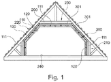
- the figure 1 schematically illustrates, in section, a lining system 100 according to the invention attached to a structure to be doubled 200. More particularly, this figure 1 illustrates an implementation of the lining system 100 according to the invention in the attic of a dwelling.
- the structure to be doubled 200 comprises both straight walls 210, that is to say perpendicular to a floor 240, inclined walls 220, and a roof 230.
- the structure to be doubled could also be formed by the floor without departing from the context of the present invention.
- the lining system 100 comprises at least one insulation layer 110 and a facing 120 fixed to the structure to be lined 200 by means of at least one spacer device 301, advantageously a plurality of spacer devices 301
- Each spacer device 301 comprises at least fixing kit 300 which comprises at least one anchoring means on the structure to be lined, at least one wing for positioning the insulation layer coming from the anchoring means and at least a facing fixing plate.
- the insulation layer 110 comprises a plurality of insulation panels 111 juxtaposed to each other.
- These insulation panels 111 each have two main faces 112 - only one being visible on the figure 2 - And at least one edge 113 connecting said main faces 112.
- each insulation panel 111 comprises at least two perpendicular edges 113 connecting the main faces 112 of the insulation panel 111 concerned.
- these insulation panels 111 are vacuum panels and more particularly they comprise bulk silica encapsulated under vacuum in an aluminum foil, or in a foil of a synthetic material.
- the spacer devices 301 according to the invention make it possible to fix these insulation panels 111 to the structure to be lined 200 without drilling, cutting, or other action which would lead to their degradation and the loss of their thermal insulation properties.
- the figure 2 illustrates more particularly the structure to be doubled 200 on which are fixed a plurality of spacer devices 301, these spacer devices 301 maintaining the insulation panels 111 in position. So this figure 2 makes the fixing plate 320 of each of these spacer devices 301 particularly visible.
- these fixing plates 320 are intended to receive the facing.
- This facing can for example comprise a plurality of plates of a construction material, such as plasterboard or wood plates for example.
- This facing can be screwed on, or glued to the fixing plates 320, for example by means of an adhesive or an adhesive element of the film or tape type. He is heard that any other means of maintaining this facing on the fixing plates 320 can be envisaged without departing from the context of the present invention.
- This figure 2 also illustrates the fact that the bracing device 301 is suitable for being fixed to different types of surfaces, such as for example rafters 221 of a frame, or else a wall 222 made of concrete, cinder block, brick or wood .
- the figures 3 to 5 more particularly illustrate the spacer device 301 according to a first embodiment of the present invention, the figure 3 being a perspective view of the spacer device 301 assembled and the figure 4 being a first exploded view of this spacer device 301 and the figure 5 being a second exploded view of this spacer device 301.
- the spacer device 301 comprises the anchoring means 310 to the structure to be doubled, a positioning wing 330 of the insulation layer, a holding plate 340 and the fixing plate 320 of the facing.
- the anchoring means 310, the positioning wing 330 of the insulation layer, the retaining plate 340 and the fixing plate 320 are aligned, in that order, along a direction of. dubbing X.
- the anchoring means 310 comprises an anchoring plate 311 which extends mainly in a first plane P1.
- the positioning wing 330 for its part comes from the anchoring plate 311 and it has at least a first bearing surface 331 intended to receive an insulation panel, and more particularly an edge of this insulation panel.
- the positioning wing 330 extends mainly in a second plane P2, transverse and advantageously perpendicular to the first plane P1.
- the positioning wing 330 is adapted to receive at least two insulation panels, each of these insulation panels extending in a plane parallel to the first plane P1 in which the anchoring plate 311 mainly fits. .
- the anchoring plate 311 and the positioning wing 331 form a T-shaped structure, that is to say an angle ⁇ formed between the first plane P1 in which mainly fits the anchoring plate 311 and the second plane P2 in which mainly fits the positioning wing 330 is equal to or substantially equal to 90 °.
- the anchoring plate 311 and the first bearing surface 331 can, alternatively, form an L-shaped structure, the angle formed between the first plane and the second plane also being equal to, or substantially equal to 90 °.
- the anchoring plate 311 and the positioning wing 330 form a one-piece assembly, that is to say a single assembly which cannot be separated without causing damage to the anchoring plate 311 or of the positioning wing 330.
- the anchoring plate 311 has a square shape so that it can be positioned in two distinct perpendicular positions, depending on the direction in which it is desired to insert the insulation panel between the fixing plate 311 and the mounting plate. holding 340.
- this square shape of the fixing plate 311 advantageously makes it possible to adapt the assembly to the size of the environment.
- the anchoring plate can have a circular shape.
- the positioning wing 330 is placed between two adjacent insulation panels, the positioning wing 330 being able to extend along a horizontal direction, or substantially horizontal, or in a vertical direction, or substantially vertical. In the case where the positioning wing 330 is horizontal, the latter carries two insulation panels.
- the anchoring plate 311 has a height h equal between 100 mm and 150 mm. As shown, the height h of this anchoring plate 311 corresponds to a dimension, the longest, measured between two parallel edges of this anchoring plate 311, in a direction perpendicular to these edges.
- the retaining plate 340 extends mainly in a third plane P3 transverse to the second plane P2 in which the first bearing surface 331 is mainly inscribed. According to the particular example illustrated in figures 3 to 5 , this third plane P3 is perpendicular to the second plane P2 in which the first bearing surface 331 is inscribed and parallel to the first plane P1 in which the fixing plate 320 is mainly inscribed.
- This support plate 340 is provided with at least a first fixing means 341 configured to allow the attachment of this support plate 340 to the positioning wing 330.
- this first fixing means 341 comprises at least one opening 342 through which extends the positioning wing 330 and at least one first locking means 370 of the retaining plate 340 on the positioning wing 330.
- the opening 342 takes the form of a slot formed through a constituent plate of the retaining plate 340.
- This opening 342 is delimited by a main reinforcement 343 which extends over an entire width of the retaining plate, c ' that is to say between two opposite edges of this support plate 340, away from the support plate 340, towards the fixing plate 320.
- This main reinforcement 343 comprises at least two parallel plates 344 arranged at a distance from one of the 'other, this distance forming the opening 342 and this distance being thus calculated to allow at least the passage of the positioning wing 330.
- Each of these plates 344 is also secured to the retaining plate 340 thanks to secondary reinforcements 345 .
- the support plate 340 comprises three secondary reinforcements 345 arranged at an equal distance from each other, along the main reinforcement 343. As shown, these secondary reinforcements 345 extend transversely, advantageously perpendicularly, to the reinforcement main 343. It is also noted that the main reinforcement 343 and the secondary reinforcements 345 extend away from the retaining plate 340, in the direction of the fixing plate 320.
- this makes it possible to ensure that a space left between the anchor plate 311 and the support plate 340 is completely free to receive one of the insulation panels.
- these insulation panels can thus be arranged edge to edge with respect to each other, thus avoiding the creation of thermal bridges.
- the first locking means 370 of the first fixing means 341 is formed by at least one screw.
- the first locking means 370 more particularly comprises two screws. These screws are received in holes 346 pre-drilled in the main reinforcement 343 which delimits the opening 342. These screws also pass through the positioning flange 330.
- the holes for receiving the screws in the positioning wing 330 are made directly during screwing. It is understood that this is only an exemplary embodiment and that all of the orifices could be pre-drilled, or on the contrary formed directly during screwing without departing from the context of the present invention.
- At least one face 360 of the retaining plate 340 is thus arranged to bear against the insulation panel disposed at the level of the first bearing surface 331 of the spacer device 301 concerned.
- this face 360 of the retaining plate 340 is arranged to bear against the two insulation panels supported by the first bearing surface 331 of the spacer device 301 concerned.
- this at least one face 360 of the retaining plate 340 is arranged to bear against one of the main faces of the insulation panel concerned.
- this face 360 is flat, that is to say that it has no roughness so as not to risk damaging the insulation panel concerned.
- the fixing plate 320 for its part comprises at least one second bearing surface 321 on which the facing as described above is fixed. 15.
- this second bearing surface 321 has a transverse dimension T1, that is to say a dimension measured between two edges of the second bearing surface 321 opposite, along a transverse direction Y perpendicular to the lining direction X, greater than or equal to 30 mm, preferably greater than or equal to 45 mm.
- the second bearing surface 321 has dimensions which are identical, or substantially identical, to the dimensions of the fixing plate 320 mentioned above.
- the fixing plate 320 further comprises a second fixing means 322.
- this second fixing means 322 is configured to allow the fixing of the fixing plate 320 on the positioning wing 330.
- this second fixing means 322 comprises at least one second locking means 323 of the mounting plate.
- fixing 320 on the positioning wing 330 and at least one blind tunnel 328 which extends from the fixing plate 320 and which receives this positioning wing 330.
- this terminal tunnel 328 has at least one open end 329 which receives the positioning wing 330 and one end closed by the fixing plate 320.
- the second locking means 323 takes the form of two screws which pass through the blind tunnel 328 and the positioning wing 330. Similar to what has been described above, these screws can be received in pre-drilled bores or, alternatively, such bores can be made directly during screwing.
- the anchoring plate 311 comprises at least one third fixing means 312 configured to allow the fixing of this anchoring plate 311 on the structure to be doubled.
- this third fixing means 312 comprises at least one hole 313 and a fixing screw 314 received in at least one hole 313.
- this hole 313 is an oblong hole, which makes it possible to give a degree of freedom to the fixing of the anchoring plate 311 on the structure to be doubled, thus allowing a certain tolerance as to the width of the insulation panels held by the spacer devices 301 according to the invention, the width of a panel being measured between two opposite edges of this panel, parallel to the transverse direction Y illustrated in the drawings.
- a guard zone 350 is also provided between the retaining plate 340 and the fixing plate 320.
- this guard zone 350 makes it possible to pass, for example, electric power cables, and thus hide these cables in the final construction. Even more advantageously, this guard zone 350 makes it possible to ensure that the fixing means used to fix the facing on the fixing plate 320 do not damage the insulation panel received between the anchoring plate 311 and the plate. hold 340.
- bracing devices 301 In order to allow each spacer device 301, and more particularly the first bearing surfaces 311 of these spacer devices 301, to support at minus two insulation panels, these bracing devices 301 have particular dimensions detailed with reference to the figure 5 .
- the anchor plate 311 is thus defined by at least its height h and a transverse dimension T2 measured between two opposite edges of the anchor plate 311, along the transverse direction Y perpendicular to the doubling direction X.
- the positioning wing 330 and more particularly the first bearing surface 331 formed on this positioning wing 330 is defined by at least one length L measured parallel to the lining direction X, between one face of the anchoring means 310 from which extends the positioning wing 330 and a free edge 334 of this positioning wing 330, that is to say an edge of this positioning wing 330 through which it is inserted into the opening 342 formed in the constituent plate of the support plate 340, and a transverse dimension T3 measured between two edges of the positioning wing 330 opposite, along the transverse direction Y perpendicular to the doubling direction X.
- the positioning wing 330 has a thickness E less than or equal to 3 mm.
- This thickness E is measured between two edges of the positioning wing 330 opposite to each other, in a direction perpendicular to these two edges and perpendicular to the lining direction X and to the direction transverse Y to this direction of X lining.
- a thickness makes it possible to further reduce the risks of the formation of thermal bridges.
- the positioning wing 330 comprises a synthetic material.
- the anchoring means 310, the positioning wing 330, the retaining plate 320 and the fixing plate 340 comprise, respectively, a synthetic material.
- the support plate 340 is defined by at least one height h2 measured between two parallel edges of this support plate 340, in a direction perpendicular to these edges and by at least one transverse dimension T4 measured between two edges of the support plate 340 opposite , along the transverse direction Y.
- the fixing plate 320 is for its part defined by its transverse dimension T1 as defined above, and by at least one height h3 measured between two parallel edges of this fixing plate 320, in a direction perpendicular to these edges.
- the transverse dimension T3 of this first bearing surface 331 is greater than or equal to 45 mm.
- the length L of this first bearing surface 331 is greater than or equal to 70mm.
- a ratio between an area of the first bearing surface 331 of the positioning wing 330 on a surface of the anchoring means is between 0.59 and 0.73
- a ratio between the area of the first bearing surface 331 and an area of the retaining plate is between 0.59 and 0.73
- a ratio between the area of the first bearing surface 331 and an area of the fixing plate 320 is between 0.59 and 0.73.
- the figures 6 and 7 illustrate the spacer device 301 according to a second exemplary embodiment of the present invention.
- This second exemplary embodiment differs from the first exemplary embodiment in particular in that the second fixing means 322 enables the fixing plate 320 to be fixed on the retaining plate 340, rather than on the anchoring means 310 as is the case. case of the first embodiment described above. It will be understood that, according to this second exemplary embodiment, the second fixing means 322 is distributed between the fixing plate 320 and the retaining plate 340.
- the dimensions given above, with reference to the figure 5 apply mutatis mutandis to the spacer device 301 according to the second exemplary embodiment of the invention.
- this second fixing means 322 thus comprises a rod 324 which extends parallel, or substantially parallel, to the doubling direction X and at least one recess 325 configured to receive this rod 324. More particularly, this rod 324 comprises at least one primary rib 326 formed at the periphery of this rod 324, that is to say on an external perimeter of this rod 324, and the recess 325 in turn comprises at least one secondary rib 327 which protrudes in the recess 325 is which is intended to cooperate with at least one primary rib 326 so as to secure the retaining plate 340 with the fixing plate 320.
- the rod 324 has a cross section, that is to say a section with four branches 361, at least one primary rib 326 being formed in at least one groove 362 delimited by two successive branches 361.
- two primary ribs 326 are formed in two non-successive grooves 362.
- the rod 324 is inserted into the recess 325 so that the secondary rib 327 formed in this recess 325 slides in one of the grooves 362 devoid of a primary rib 326, then the rod 324 is turned by a quarter of a turn so that at least one of the primary ribs 326 formed on this rod 324 abuts against the secondary rib 327, thus blocking in translation along the doubling direction X, the fixing plate 320 on the plate holding 340.
- this example of the second fixing means is particularly advantageous for the technician for whom the invention is intended since it allows simple and rapid mounting of each fixing plate 320 on each holding plate 340.
- the rod 324 is carried by the retaining plate 340 and the recess 325 is made through the fixing plate 320 but it is understood that the elements could be reversed, that is to say that the rod 324 can be carried by the fixing plate 320 and the recess 325 can be made in the retaining plate 340, without departing from the context of the present invention.
- this second embodiment has the advantage of reducing the number of fixing means to be put in place.
- this second exemplary embodiment makes it possible to save the screw (s) otherwise used to fix the fixing plate to the retaining plate, which represents, on a large scale, savings in time and money.
- This second exemplary embodiment also differs from the first exemplary embodiment by the extent of the opening 342 which receives the positioning wing 330.
- the plate of holder 340 comprises a single opening which extends between two opposite edges of the holder plate while, according to the second exemplary embodiment illustrated in figures 6 and 7 , two openings 342 are formed in the holding plate 340, on either side of the rod 324 which participates in forming the second fixing means 322.
- the positioning wing 330 is itself separate, from its end opposite to the anchoring plate 311, in two branches 332 parallel to each other, each of these branches 332 being intended to be received in one of the openings 342 of the holding plate 340.
- the holding plate 340 comprises the recess 325 rather than the rod 324, the openings 342 are distributed on both sides on the other side of this recess 325.
- the retaining plate 340 abuts against a portion 336 of the positioning wing 330 from which extend the two branches 332.
- the first bearing surface 331 is, according to the example illustrated. on the figures 6 and 7 , delimited on the one hand by the fixing plate 311 and on the other hand by this section 336 of the positioning wing 330.
- each sleeve 352 is formed by one of the openings 342 of the first fixing means and a second end 354 of the sleeve 352, opposite to the first end 353 along the X-doubling direction, is closed by the fixing plate 320.
- screws passing through the sleeves 352 and the branches 332 can also be put in place to ensure the fixing of the support plate 340 on the positioning wing 330 , these screws then forming the second fixing means mentioned above.
- the sleeves can be made from one material with the retaining plate, that is to say that they then form a single assembly which cannot be separated without causing the deterioration of at least one of the sleeves or of the holding plate.
- the spacer device comprises only a single sleeve, whether or not made from material with the retaining plate, this sleeve then comprising a groove for receiving the rod.
- this second exemplary embodiment provision may be made to interpose a sealing membrane between the fixing plate and the plate. maintenance.
- the waterproofing membrane is more particularly held by the rod and pierced exclusively by this rod, thus limiting the flow of air and water vapor.
- the sealing membrane is pierced by the rod and then this rod is inserted into the recess as described above.
- this waterproofing membrane called the vapor barrier membrane, is made of a material which allows water vapor to pass more or less.
- the figure 8 illustrates a first variant embodiment of the present invention in which the first locking means 370 of the first fixing means of the retaining plate 340 on the anchoring means 310 forms a means of adjusting the position of the retaining plate 340 by in relation to the anchoring plate 311.
- the first locking means 370 according to this first variant embodiment of the invention makes it possible to adjust a distance between the retaining plate 340 and the anchoring plate 311. More particularly this distance is measured between the anchor plate 311 and the support plate 320, parallel to the doubling direction X.
- this first variant of the present invention makes it possible to carry out an adjustment along this doubling direction X so to be able to use the same spacer device 301 for fixing insulation panels of different thicknesses, for example from one site to another.
- the positioning wing 330 comprises the two branches 332 described above. These branches 332 delimit an adjustment zone 333 which houses the first locking means 370 distributed between the positioning wing 330 and the retaining plate 340.
- the first locking means 370 according to this first variant comprises at least two notches 335 formed on a lateral edge of one and / or the other of the two branches 332 of the positioning wing 330 and at least one tooth 348 carried by the retaining plate 340 and configured to come into abutment against one of the notches 335 carried by the positioning wing 330 so as to block the positioning wing 330 in position relative to the holding plate 340, along the doubling direction X.
- the first locking means 370 according to this first variant comprises a plurality of notches 335 with which at least one tooth 348 is able to cooperate.
- the holding plate 340 comprises two tabs 349 which extend parallel to the doubling direction X away from the holding plate 340, towards the fixing plate 320, and which are each provided with a tooth 348 whose function was explained in the previous paragraph.
- These two teeth 348 extend away from one another in a direction Y transverse to the doubling direction X, for example orthogonally.
- each of these tongues 349 is elastically deformable in the second plane P2 in which extends mainly the first bearing surface 331 intended to receive the edge of the insulation panel.
- the distance between the anchoring plate 320 and the support plate 340 is controlled by the choice of the notches 335 at the abutment of which the teeth 348 carried by the support plate 340 are arranged.
- This first variant thus makes it possible to using the spacer device 301 according to the invention with insulation panels which have different thicknesses. Advantageously, this allows a standardization of the part, and thus economies of scale during production.
- the first fixing means illustrated on figure 8 also differs from the embodiments previously described by the opening 342.
- the first fixing means thus comprises two openings 342 distributed on either side of the two tongues 349 and which extend to an edge of the retaining plate 340.
- these openings 342 have, according to the example shown on figure 8 , a transverse end, that is to say an end along the transverse direction Y, open.
- a means for adjusting a distance measured between the holding plate and the fixing plate, along the dubbing direction may for example be made to pass various cables, for example power supply cables, in the guard zone generated between this fixing plate and the retaining plate.
- an adjustment means thus makes it possible to adapt the size of the guard zone formed between the retaining plate and the fixing plate according to the elements which one wishes to pass through it.
- the figure 9 illustrates a second variant of the present invention, also applicable both to the first and to the second exemplary embodiments described above.
- the anchoring plate 311 comprises a return 316 which extends transversely to this anchoring plate 311, away from the positioning wing 330.
- the return 316 and the positioning wing 330 both emerge from the mounting plate 311 and extend away from each other, in two opposite directions, i.e. they each emerge from a separate face of the fixing plate 311.
- the return 316 extends mainly in a fourth plane P4 transverse to the first plane P1 in which mainly extends the anchoring plate 311.
- the first plane P1 and the fourth plane P4 are perpendicular to each other.
- an oblong hole 317 is made in this return 316, this oblong hole 317 being intended to receive a fixing member, such as for example a screw.
- a fixing member such as for example a screw.
- this oblong hole 317 formed in the return 316 as described above makes it possible to secure the anchoring plate 311 on one side of the structure to be doubled, rather than on one face of this structure to be doubled oriented towards the room to be insulated, that is to say in particular in the case where the structure to be doubled is formed by rafters.
- this oblong hole 317 gives a degree of freedom to the fixing of the spacer device 301 on the structure to be lined, which makes it possible to properly align all of the spacer devices 301. used on the same structure to be doubled, so as to align, at least, the respective fixing plates 320 of these spacer devices 301, and therefore, ultimately, to align the facings fixed to these fixing plates 320.
- the invention therefore proposes a simple and capable of being standardized means for supporting thermal insulation panels, in particular under vacuum, with respect to the structure of a building without having to damage in any way the said thermal insulation panel. insulation, that is to say without cutting or traumatic fixing means. It is understood that the invention is not limited to the means described and illustrated here and that it also extends to any equivalent means and configuration and to any technically operative combination of such means.
- the fixing means described for fixing the different parts of the spacer device to each other and for fixing the spacer device on the structure to be doubled can be modified without harming the invention insofar as they meet the requirements. features described in this document.
Applications Claiming Priority (1)
| Application Number | Priority Date | Filing Date | Title |
|---|---|---|---|
| FR1909290A FR3100041B1 (fr) | 2019-08-20 | 2019-08-20 | Kit de fixation d’un système de doublage sur une structure à doubler |
Publications (1)
| Publication Number | Publication Date |
|---|---|
| EP3783166A1 true EP3783166A1 (de) | 2021-02-24 |
Family
ID=69375415
Family Applications (1)
| Application Number | Title | Priority Date | Filing Date |
|---|---|---|---|
| EP20188522.5A Pending EP3783166A1 (de) | 2019-08-20 | 2020-07-30 | Abstandsvorrichtung, die ein kit zur befestigung eines auskleidungssystems an einer auszukleidenden struktur umfasst |
Country Status (2)
| Country | Link |
|---|---|
| EP (1) | EP3783166A1 (de) |
| FR (1) | FR3100041B1 (de) |
Cited By (1)
| Publication number | Priority date | Publication date | Assignee | Title |
|---|---|---|---|---|
| CN115411461A (zh) * | 2022-10-10 | 2022-11-29 | 厦门海辰储能科技股份有限公司 | 线束隔离板及电池模组 |
Citations (9)
| Publication number | Priority date | Publication date | Assignee | Title |
|---|---|---|---|---|
| DE1056349B (de) * | 1954-08-02 | 1959-04-30 | Eckel Oliver C | Vorrichtung zum Befestigen von Bauteilen, insbesondere Isolierplatten |
| EP0561657A1 (de) * | 1992-03-18 | 1993-09-22 | Rocamat | Vorrichtung zur Befestigung von Verblendungsplatten |
| EP0921252A2 (de) * | 1997-12-02 | 1999-06-09 | SFS Industrie Holding AG | Befestigungselement zur Abstandsbefestigung von Latten, Profilen, Platten oder dergleichen an einem festen Untergrund, Hilfsvorrichtung zum Bohren von Löchern in einem Untergrund zum Einsetzen der Befestigungselemente sowie Verfahren zur Abstandsbefestigung unter Einsatz eines solchen Befestigungselementes |
| FR2849461A1 (fr) * | 2002-12-26 | 2004-07-02 | Saint Gobain Isover | Systeme pour maintenir et regler la distance a une paroi d'un profile destine a l'appui d'un parement |
| WO2013088075A1 (fr) * | 2011-12-14 | 2013-06-20 | Electricite De France | Système d'isolation thermique avec appuis intermédiaires pour maintenir des panneaux piv et procédé d'assemblage associé |
| FR3022935A1 (fr) * | 2014-06-26 | 2016-01-01 | Lr Etanco Atel | Systeme pour realiser une etancheite a l'air le long d'un mur. |
| US20160040425A1 (en) * | 2014-08-05 | 2016-02-11 | Kamran Farahmandpour | Façade Wall Attachment System |
| US20170130464A1 (en) * | 2015-11-06 | 2017-05-11 | James Hardie Technology Limited | Adjustable building panel support device |
| US20170342724A1 (en) * | 2016-05-26 | 2017-11-30 | Kamran Farahmandpour | Cladding Tie |
-
2019
- 2019-08-20 FR FR1909290A patent/FR3100041B1/fr active Active
-
2020
- 2020-07-30 EP EP20188522.5A patent/EP3783166A1/de active Pending
Patent Citations (9)
| Publication number | Priority date | Publication date | Assignee | Title |
|---|---|---|---|---|
| DE1056349B (de) * | 1954-08-02 | 1959-04-30 | Eckel Oliver C | Vorrichtung zum Befestigen von Bauteilen, insbesondere Isolierplatten |
| EP0561657A1 (de) * | 1992-03-18 | 1993-09-22 | Rocamat | Vorrichtung zur Befestigung von Verblendungsplatten |
| EP0921252A2 (de) * | 1997-12-02 | 1999-06-09 | SFS Industrie Holding AG | Befestigungselement zur Abstandsbefestigung von Latten, Profilen, Platten oder dergleichen an einem festen Untergrund, Hilfsvorrichtung zum Bohren von Löchern in einem Untergrund zum Einsetzen der Befestigungselemente sowie Verfahren zur Abstandsbefestigung unter Einsatz eines solchen Befestigungselementes |
| FR2849461A1 (fr) * | 2002-12-26 | 2004-07-02 | Saint Gobain Isover | Systeme pour maintenir et regler la distance a une paroi d'un profile destine a l'appui d'un parement |
| WO2013088075A1 (fr) * | 2011-12-14 | 2013-06-20 | Electricite De France | Système d'isolation thermique avec appuis intermédiaires pour maintenir des panneaux piv et procédé d'assemblage associé |
| FR3022935A1 (fr) * | 2014-06-26 | 2016-01-01 | Lr Etanco Atel | Systeme pour realiser une etancheite a l'air le long d'un mur. |
| US20160040425A1 (en) * | 2014-08-05 | 2016-02-11 | Kamran Farahmandpour | Façade Wall Attachment System |
| US20170130464A1 (en) * | 2015-11-06 | 2017-05-11 | James Hardie Technology Limited | Adjustable building panel support device |
| US20170342724A1 (en) * | 2016-05-26 | 2017-11-30 | Kamran Farahmandpour | Cladding Tie |
Cited By (3)
| Publication number | Priority date | Publication date | Assignee | Title |
|---|---|---|---|---|
| CN115411461A (zh) * | 2022-10-10 | 2022-11-29 | 厦门海辰储能科技股份有限公司 | 线束隔离板及电池模组 |
| CN115411461B (zh) * | 2022-10-10 | 2023-09-08 | 厦门海辰储能科技股份有限公司 | 线束隔离板及电池模组 |
| WO2024078425A1 (zh) * | 2022-10-10 | 2024-04-18 | 厦门海辰储能科技股份有限公司 | 线束隔离板及电池模组 |
Also Published As
| Publication number | Publication date |
|---|---|
| FR3100041B1 (fr) | 2021-10-22 |
| FR3100041A1 (fr) | 2021-02-26 |
Similar Documents
| Publication | Publication Date | Title |
|---|---|---|
| EP2791441B1 (de) | Wärmedämmsystem und entsprechendes montageverfahren | |
| WO2001021904A1 (fr) | Structure acoustique de batiment | |
| EP3783166A1 (de) | Abstandsvorrichtung, die ein kit zur befestigung eines auskleidungssystems an einer auszukleidenden struktur umfasst | |
| FR2984380A1 (fr) | Systeme d'isolation thermique avec appuis intermediaires pour maintenir des panneaux piv et procede d'assemblage associe | |
| EP3009582B1 (de) | Verstrebungsvorrichtung für die befestigung eines halteprofils für eine hohltrennwand einer zu dämmenden wand | |
| EP0974706B1 (de) | Verstellbare Trennwand | |
| EP3196372B1 (de) | Wärmedämmsystem und -verfahren, bei dem verbundpaneele zur definition einer dämmschicht für vip-elemente verwendet werden | |
| FR2996237A1 (fr) | Panneau de toiture | |
| EP2959074B1 (de) | Bausatz zum anbringen eines wandbelags, geeignet zum halten von vips und entsprechender stützprofilabschnitt | |
| CA3104029A1 (fr) | Dispositif d'entretoisement pour la fixation d'un parement | |
| EP2959073B1 (de) | Befestigungsset zum halten von vip sowie zugehörige verfahrung und vorrichtung zum verkleiden einer wand | |
| EP0426187A1 (de) | Fassadensystem zur Abschliessung von Gebäuden von Decke zu Decke | |
| FR2526837A1 (fr) | Panneau de veture externe comportant son dispositif de fixation | |
| EP2860320B1 (de) | Wärmeisolierter Boden mit Vakuumisolationspaneelen (VIP), Bodenmodul und Montage-Kit | |
| FR3090028A1 (fr) | Appui de fenêtre ou élément de seuil, pièce de débord pour un tel appui, et leur procédé de mise en œuvre | |
| EP3916168B1 (de) | Abstandhalter für die auskleidung einer wand | |
| FR2977265A1 (fr) | Panneau composite pour l'isolation thermique de facade de batiments | |
| FR2865750A1 (fr) | Procede de construction de batiments a ossature bois et elements pour sa mise en oeuvre | |
| FR2885376A1 (fr) | Systeme mecanique d'alignement de panneaux multicouches | |
| EP3832049A1 (de) | Wandverkleidung eines gebäudes | |
| EP2868836A1 (de) | Vorrichtung und Verfahren zur Montage eines Gegenstands an einer Wand | |
| FR3090573A1 (fr) | Panneau de revêtement mural pour aéronef à isolation intégrée | |
| FR3103839A1 (fr) | Revêtement de façade d’un mur d’un bâtiment. | |
| FR3020519A1 (fr) | Bouchon monobloc encastrable d'etancheite a l'air | |
| FR2974385A1 (fr) | Panneau de porte comprenant un insert decoratif |
Legal Events
| Date | Code | Title | Description |
|---|---|---|---|
| PUAI | Public reference made under article 153(3) epc to a published international application that has entered the european phase |
Free format text: ORIGINAL CODE: 0009012 |
|
| STAA | Information on the status of an ep patent application or granted ep patent |
Free format text: STATUS: THE APPLICATION HAS BEEN PUBLISHED |
|
| AK | Designated contracting states |
Kind code of ref document: A1 Designated state(s): AL AT BE BG CH CY CZ DE DK EE ES FI FR GB GR HR HU IE IS IT LI LT LU LV MC MK MT NL NO PL PT RO RS SE SI SK SM TR |
|
| AX | Request for extension of the european patent |
Extension state: BA ME |
|
| STAA | Information on the status of an ep patent application or granted ep patent |
Free format text: STATUS: REQUEST FOR EXAMINATION WAS MADE |
|
| 17P | Request for examination filed |
Effective date: 20210824 |
|
| RBV | Designated contracting states (corrected) |
Designated state(s): AL AT BE BG CH CY CZ DE DK EE ES FI FR GB GR HR HU IE IS IT LI LT LU LV MC MK MT NL NO PL PT RO RS SE SI SK SM TR |
|
| STAA | Information on the status of an ep patent application or granted ep patent |
Free format text: STATUS: EXAMINATION IS IN PROGRESS |
|
| 17Q | First examination report despatched |
Effective date: 20221130 |