EP4530586A2 - Kraftsensor mit target auf halbleitergehäuse - Google Patents
Kraftsensor mit target auf halbleitergehäuse Download PDFInfo
- Publication number
- EP4530586A2 EP4530586A2 EP25157905.8A EP25157905A EP4530586A2 EP 4530586 A2 EP4530586 A2 EP 4530586A2 EP 25157905 A EP25157905 A EP 25157905A EP 4530586 A2 EP4530586 A2 EP 4530586A2
- Authority
- EP
- European Patent Office
- Prior art keywords
- sensing element
- flexible piece
- magnet
- sensor
- semiconductor package
- Prior art date
- Legal status (The legal status is an assumption and is not a legal conclusion. Google has not performed a legal analysis and makes no representation as to the accuracy of the status listed.)
- Pending
Links
Images


Classifications
-
- G—PHYSICS
- G01—MEASURING; TESTING
- G01L—MEASURING FORCE, STRESS, TORQUE, WORK, MECHANICAL POWER, MECHANICAL EFFICIENCY, OR FLUID PRESSURE
- G01L5/00—Apparatus for, or methods of, measuring force, work, mechanical power, or torque, specially adapted for specific purposes
- G01L5/22—Apparatus for, or methods of, measuring force, work, mechanical power, or torque, specially adapted for specific purposes for measuring the force applied to control members, e.g. control members of vehicles, triggers
- G01L5/226—Apparatus for, or methods of, measuring force, work, mechanical power, or torque, specially adapted for specific purposes for measuring the force applied to control members, e.g. control members of vehicles, triggers to manipulators, e.g. the force due to gripping
-
- G—PHYSICS
- G01—MEASURING; TESTING
- G01G—WEIGHING
- G01G7/00—Weighing apparatus wherein the balancing is effected by magnetic, electromagnetic, or electrostatic action, or by means not provided for in the preceding groups
- G01G7/02—Weighing apparatus wherein the balancing is effected by magnetic, electromagnetic, or electrostatic action, or by means not provided for in the preceding groups by electromagnetic action
-
- B—PERFORMING OPERATIONS; TRANSPORTING
- B25—HAND TOOLS; PORTABLE POWER-DRIVEN TOOLS; MANIPULATORS
- B25J—MANIPULATORS; CHAMBERS PROVIDED WITH MANIPULATION DEVICES
- B25J13/00—Controls for manipulators
- B25J13/08—Controls for manipulators by means of sensing devices, e.g. viewing or touching devices
- B25J13/081—Touching devices, e.g. pressure-sensitive
- B25J13/082—Grasping-force detectors
-
- G—PHYSICS
- G01—MEASURING; TESTING
- G01L—MEASURING FORCE, STRESS, TORQUE, WORK, MECHANICAL POWER, MECHANICAL EFFICIENCY, OR FLUID PRESSURE
- G01L1/00—Measuring force or stress, in general
- G01L1/04—Measuring force or stress, in general by measuring elastic deformation of gauges, e.g. of springs
-
- G—PHYSICS
- G01—MEASURING; TESTING
- G01L—MEASURING FORCE, STRESS, TORQUE, WORK, MECHANICAL POWER, MECHANICAL EFFICIENCY, OR FLUID PRESSURE
- G01L1/00—Measuring force or stress, in general
- G01L1/12—Measuring force or stress, in general by measuring variations in the magnetic properties of materials resulting from the application of stress
- G01L1/122—Measuring force or stress, in general by measuring variations in the magnetic properties of materials resulting from the application of stress by using permanent magnets
-
- G—PHYSICS
- G01—MEASURING; TESTING
- G01L—MEASURING FORCE, STRESS, TORQUE, WORK, MECHANICAL POWER, MECHANICAL EFFICIENCY, OR FLUID PRESSURE
- G01L1/00—Measuring force or stress, in general
- G01L1/12—Measuring force or stress, in general by measuring variations in the magnetic properties of materials resulting from the application of stress
- G01L1/127—Measuring force or stress, in general by measuring variations in the magnetic properties of materials resulting from the application of stress by using inductive means
-
- G—PHYSICS
- G01—MEASURING; TESTING
- G01L—MEASURING FORCE, STRESS, TORQUE, WORK, MECHANICAL POWER, MECHANICAL EFFICIENCY, OR FLUID PRESSURE
- G01L1/00—Measuring force or stress, in general
- G01L1/14—Measuring force or stress, in general by measuring variations in capacitance or inductance of electrical elements, e.g. by measuring variations of frequency of electrical oscillators
-
- G—PHYSICS
- G01—MEASURING; TESTING
- G01L—MEASURING FORCE, STRESS, TORQUE, WORK, MECHANICAL POWER, MECHANICAL EFFICIENCY, OR FLUID PRESSURE
- G01L5/00—Apparatus for, or methods of, measuring force, work, mechanical power, or torque, specially adapted for specific purposes
- G01L5/16—Apparatus for, or methods of, measuring force, work, mechanical power, or torque, specially adapted for specific purposes for measuring several components of force
- G01L5/164—Apparatus for, or methods of, measuring force, work, mechanical power, or torque, specially adapted for specific purposes for measuring several components of force using variations in inductance
-
- G—PHYSICS
- G01—MEASURING; TESTING
- G01L—MEASURING FORCE, STRESS, TORQUE, WORK, MECHANICAL POWER, MECHANICAL EFFICIENCY, OR FLUID PRESSURE
- G01L5/00—Apparatus for, or methods of, measuring force, work, mechanical power, or torque, specially adapted for specific purposes
- G01L5/16—Apparatus for, or methods of, measuring force, work, mechanical power, or torque, specially adapted for specific purposes for measuring several components of force
- G01L5/169—Apparatus for, or methods of, measuring force, work, mechanical power, or torque, specially adapted for specific purposes for measuring several components of force using magnetic means
-
- G—PHYSICS
- G01—MEASURING; TESTING
- G01R—MEASURING ELECTRIC VARIABLES; MEASURING MAGNETIC VARIABLES
- G01R33/00—Arrangements or instruments for measuring magnetic variables
- G01R33/0047—Housings or packaging of magnetic sensors ; Holders
-
- G—PHYSICS
- G01—MEASURING; TESTING
- G01R—MEASURING ELECTRIC VARIABLES; MEASURING MAGNETIC VARIABLES
- G01R33/00—Arrangements or instruments for measuring magnetic variables
- G01R33/02—Measuring direction or magnitude of magnetic fields or magnetic flux
- G01R33/06—Measuring direction or magnitude of magnetic fields or magnetic flux using galvano-magnetic devices
- G01R33/07—Hall effect devices
- G01R33/072—Constructional adaptation of the sensor to specific applications
-
- A—HUMAN NECESSITIES
- A47—FURNITURE; DOMESTIC ARTICLES OR APPLIANCES; COFFEE MILLS; SPICE MILLS; SUCTION CLEANERS IN GENERAL
- A47J—KITCHEN EQUIPMENT; COFFEE MILLS; SPICE MILLS; APPARATUS FOR MAKING BEVERAGES
- A47J42/00—Coffee mills; Spice mills
- A47J42/38—Parts or details
- A47J42/44—Automatic starting or stopping devices; Warning devices
Definitions
- the invention relates to the field of force sensors. More specifically it relates to force sensors using position sensing, a sensor assembly, and a manufacture method.
- Force sensors can be used in robotics to assist robotic manipulation of objects. While optical feedback is commonly used by robots to localize and grasp an object, the force is difficult to control, which may cause faulty manipulation or positioning of the manipulated piece, or even damage to the piece.
- Robotic clamps or hands can include force-torque sensors, for example on the mechanical part that drives the motion of the grasping pieces (claws, fingers or the like).
- this measurement is indirect. Measuring the deformation of the contact surface with the piece to be handled is not straightforward.
- the surface which contacts the piece to be grasped is flexible.
- the deformation of the surface can be measured by a position sensor.
- the position sensor usually a chip, is covered by a large block of flexible material with wide contact area, several times wider than the position sensor, ensuring reliable contact.
- these sensors usually require large footprint, which is usually available only in large robot claws for heavy duty and large industrial pieces. Additionally, robotic manipulation with these systems present hurdles or cannot be used for manipulation of delicate objects.
- the present invention provides a force sensor comprising a sensing system comprising a target piece and a sensing element.
- the sensing element is configured to sense changes of the magnetic field from motion of the target piece with respect to the sensing element, the sensing element being configured to provide a signal representative of changes of the target piece position.
- An integrated circuit comprises processing means for processing signals from the sensing element.
- the integrated circuit is packaged in a semiconductor package where its top projection forms an outline. In other words, the projection of the package with the largest area is the outline.
- the semiconductor package also known as IC package
- a flexible piece comprises the target piece for providing motion of the target piece upon contact with an external body.
- the flexible piece is attached to the semiconductor package, where the attachment area between the flexible piece and the semiconductor package is smaller than or equal to the outline of the semiconductor package.
- the flexible piece is arranged for receiving a force stimulus, so that upon exerting a force on the flexible piece, the displacement of the target piece with respect to the surface of the semiconductor package can be sensed by the sensing element.
- a compact force sensor can be obtained with low footprint, with a target embedded in a flexible piece which is directly integrated on a semiconductor package.
- the semiconductor package comprises a surface facing away from the integrated circuit and wherein the flexible piece is deposited or adhered to the surface of the semiconductor package.
- the flexible piece is an elastomeric sheet.
- the elastomeric sheet can be easily provided, for example, by molding and attaching to the semiconductor package.
- the semiconductor package has a planar shape with a lateral projection with lower area than a top projection of the semiconductor package, wherein the flexible piece is attached to that semiconductor package without extending beyond the top projection.
- the footprint of the force sensor is as large as a semiconductor package.
- the sensing element is a Hall effect-based position sensing element and the target piece is a magnetic target piece.
- the sensing element is an inductive sensing element
- the target piece is a conductive target piece
- sensing is robust against stray fields. It is a further advantage that magnetic pieces can be manipulated, as they have less influence on the electric field of the inductive sensing element.
- the target piece is a metallic sheet embedded in or provided on the flexible piece.
- a metallic sheet may be easy to provide on or within the flexible piece, for example it may be a metal plate on or embedded in the flexible piece.
- the target piece is a rigid target piece with less flexibility than the flexible piece so that the force stimulus on the target piece deforms the flexible piece.
- the target piece has a predetermined shape with a largest dimension in the top projection
- the semiconductor package have a largest dimension in the top projection
- the ratio between said dimension of the semiconductor package and said dimension of the target piece is 1.5 or larger.
- the target piece is a metal trace deposited on the flexible piece. It is an advantage of embodiment of the present invention that the sensor has a low profile.
- the target piece is a metal plate.
- the metal plate may be embedded in the flexible piece.
- the sensing element is provided between the integrated circuit and the target piece.
- the sensitivity of the sensing element is high by placing the sensing element close to the sensed target.
- the sensing element (102) is adjacent to the integrated circuit (IC).
- the senor has a low profile. It is a further advantage that the IC substrate can be offset over the flexible piece so the substrate does not receive direct stress from the contact of external objects with the flexible piece.
- the sensing element is integrated with the processing means in the integrated circuit (IC).
- the senor has very compact and a low profile.
- the present invention includes a sensor assembly comprising the force sensor of the first aspect of the present invention wherein the integrated circuit (IC) is further adapted to provide readout signals based on the processed signals from the sensing element.
- the assembly further comprises a support structure, wherein the force sensor is provided on the support structure including connections for rerouting readout signals generated in the force sensor to an external output.
- the support structure may be a PCB, but in some embodiments the sensor assembly is a PCB-less sensor.
- the present invention includes a method of manufacture of a force sensor comprising:
- providing a flexible piece including a target piece comprises embedding a target piece inside the flexible piece so the target piece is completely surrounded by the material of the flexible piece.
- attaching the flexible piece comprises attaching the flexible piece so that the top projection of said flexible piece does not extend over the top projection of the integrated circuit.
- integrated circuit reference is made to a semiconductor substrate including electronic components forming a circuit for a purpose, for example processing signals and providing readout signals based on the processed signals.
- target piece or “target” for short, reference is made to a shaped piece of material whose position variation is sensed by a sensing element.
- flexible piece reference is made to a shaped piece of material with flexible properties, for example it may be compressible, and it preferably has elastic properties so it returns to the original shape in the absence of forces. Compression on the flexible piece provides a displacement of the material matrix forming the piece.
- elastomer will be used, but the present invention is not limited to pieces made by elastomeric polymers.
- the present invention aims to improve automatized grasping and handling of objects.
- Robots grasp objects supported by computer-aided vision feedback.
- robotic hands or claws need to incorporate tactile sensors. These sensors need to be small and able to detect forces within a range sensitive enough for the required application.
- the present invention provides a force sensor for sensing contact of a robotic hand or claw with an object to be handled.
- the present invention provides force sensing based on proximity sensing using a sensing element which senses changes of position of a movable target.
- the extent of the target motion depends on the contact force (both in magnitude and direction) of the claw with the object to be handled.
- Sensing may be based on an electromagnetic sensing. For example, it may be based on the detection of variations of a magnetic or, in general, electromagnetic field, due to the target motion.
- the target may generate a magnetic field, for example it may be a magnet or it may be a conductor in which a magnetic field can be induced.
- the sensing element may sense changes of the position depending on the nature of the field.
- the sensing element produces signals which are processed by processing means in a packaged integrated circuit.
- the target piece and the sensing element may be appropriately chosen and combined, thus forming a 'sensing system' with elements adapted to cooperate with each other to generate or induce an electromagnetic field whose changes are caused by motion of the target and whose detection by the sensing element can be correlated with the amount of displacement of the target.
- a magnetic sensing element e.g. a Hall sensor
- a magnet as a target.
- Motion of the target piece due to contact is provided by an elastic or flexible piece which supports the target piece.
- the flexible piece deforms in accordance with the contact force.
- the target piece, being part of the flexible piece, also moves.
- the processing means is configured to accept the signal from the sensing element and process it to provide the contact force.
- the processing may include comparison and correlation with stored values (e.g. in a lookup table) which link the signal measured with displacement of the target, or calculation based on mathematical relationships including e.g. the compression modulus of the flexible piece, calculation of displacement of the target, etc.
- the sensing element and the processing means used to process the measurement are included in a single semiconductor package.
- the flexible piece is provided on the semiconductor package, the flexible piece being smaller than the package itself, without completely surrounding the package.
- the present invention relates to a force sensor, in particular a sensor for sensing contact forces between an object and a grabbing robotic hand or claw. It includes a sensing system including a sensing element which can sense the position displacement of a suitable target, and the target itself. It also includes a processing means (e.g. a processor) provided in a semiconductor package, also called integrated circuit package, or IC package for short, although in embodiments of the present invention the IC package also includes the sensing element, not only the IC with the processing means. The processing means receives measurement signals from the position sensing element. These signals indicate displacement of the target piece included in a flexible piece deposited on or attached to the IC package.
- a sensing system including a sensing element which can sense the position displacement of a suitable target, and the target itself.
- a processing means e.g. a processor
- IC package also includes the sensing element, not only the IC with the processing means.
- the processing means receives measurement signals from the position sensing element. These signals indicate displacement
- the target piece may comprise of magnetic material, and/or electrically conductive material, depending on the type of sensing element.
- it may be a magnet for a Hall sensing element.
- it may be a metal sheet, plate or trace, for an induction-based sensing element.
- the flexible piece does not surround completely the IC package. For example, it may only partially overlap the IC package.
- the IC package layout, or overlay, or top view, contains completely the attachment area of the flexible piece.
- the flexible piece may not extend beyond the outline of the IC package.
- the footprint of the force sensor is the area which the sensor occupies on a larger system, for example a PCB.
- the force sensor of the present invention has a footprint as large as the IC package, instead of being a large piece of rubber or other elastomer overlapping the processor and the sensing element.
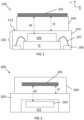
- FIG 1 shows an exemplary embodiment of a force sensor 100 including a Hall sensing element 102 placed on and connected to the integrated circuit IC.
- the sensing element 102 may be a different type of proximity detector (such an induction-based sensing element), as long as it can detect at least the variation of position of a target.
- the force sensor 100 comprises a package 105 including an integrated circuit IC and the sensing element 102 which are covered or encapsulated by a mold 103, such as resin or the like, or any other known materials.
- FIG 1 shows the sensing element 102 in contact with the integrated circuit IC, the sensing element being an element surrounded by the package 105, for example embedded in the same mold as the circuit IC, except where it is in contact with the circuit IC.
- the relative position of the sensing element with the circuit is explained below.
- the sensing element 102 may be monolithically integrated in the IC.
- the integrated circuit package 105 may be a 'small outline integrated circuit' (SOIC), a 'quad flat no leads' (QFN) package, etc.
- the package 105 has usually a flat profile, with a relatively large surface area on the top projection, compared with the small, narrow area of the lateral projection of the package 105.
- FIG 1 shows the lateral view of the sensor.
- the area of the surface corresponding to the top projection will be named top surface 113 for short. It is an external surface, facing away from the internal circuit IC. Typically it is a planar, flat surface, but it may have other profiles.
- the force sensor comprises a flexible piece 104, such as a compressible sheet or plate, for example an elastomer.
- the flexible piece includes a target piece 101, where at least one surface may be uncovered to provide contact with the piece to be grasped. For example it may be adhered on the top surface of the elastomer facing away from the top surface 113 of the package, forming a layered stack.
- the target piece may be partially or completely embedded within the flexible piece, as shown in the FIG 2 and FIG 3 described below.
- the target piece 101 may be a magnet, for example, a two pole magnet having an axial magnetization, perpendicular to the top surface of the integrated circuit IC (the surface of the IC facing the elastomer).
- the present invention is not limited to this, and magnets with other magnetization (different orientation, different multipolarity) can also be considered.
- the target piece may be a plate such as a planar plate or sheet, providing a relatively wide area for contact, thus allowing sensing contact forces. In some embodiments it may be stiffer than the flexible piece.
- the target piece may be a very thin sheet of material, e.g. a metal trace deposited on the elastomer, or embedded therein, etc.
- the target can also be formed with a suspension of discrete metallic parts in the elastomer (e.g. metallic or magnetic beads and/or powder).
- the sensing element is sensitive to changes of position of the target piece, which is in turn configured to be detected by the sensing element 102.
- the flexible piece 104 is provided on the external surface of the semiconductor package 105, for example directly on the top surface 113 of the encapsulant or mold 103.
- the 'top' refers to the part of the package facing the object to be contacted, so the flexible piece 104 is arranged for receiving a force stimulus.
- the elastomer is on the IC package, not on a different support such as a PCB or a spacer or the like. The elastomer is directly adhered to the IC package. In order to obtain a good compact force sensor, the flexible piece does not completely overlap the package.
- the flexible piece is attached to an area of the mold smaller than the top surface 113 of the mold, although in other embodiments the attachment area may be equal to the top surface 113 of the mold.
- at least part of the flexible piece may be partially embedded by the IC package, for example in its mold.
- An exemplary embodiment is shown in FIG 3 , although said configuration may be present in any other embodiment of the present invention.
- the elastomer is in contact with the IC as shown in FIG 4 below.
- the sensing element is configured to measure the relative displacement of the position of a target piece with respect to the IC package containing the sensing element. This displacement depends on force applied on the flexible piece including the target piece, from which a signal is obtained and processed by the processing means of the IC circuit.
- the sensing element is a sensing element for sensing EM fields, in particular changes of EM fields due to said motion: in case of compression, the larger the compression, the more the target will approach the sensing element, which is detected by the sensing element, and larger contact force will be detected.
- the sensing element can measure a position in general, for example a linear position, or an angular position.
- the sensing element may measure a magnetic strength, depending on the magnetic flux and changes thereof, which may be related to the proximity of the target piece to the sensing material (which in turn can be linked to the compression force).
- the sensing element may be a Hall effect-based position sensing element, and the target piece may be a magnet whose magnetic field can be sensed by the position sensing element. When a force is applied on the flexible piece, the target piece changes its position accordingly relative to the Hall sensors, which provide a measurement signal dependent of the motion of the target.
- the sensing element is an inductive sensing element with coils through which a known current flows, which generates a magnetic field through a conductive target. Changes in the target position induce a current on the target, which affects the magnetic field. This effect is detected as changes of current flowing through the inductive coils, so the sensing element can sense changes of the position of the target piece relative to the sensing element.
- the target may be a metal plate, metal trace or the like, as long as it provides sufficient conductance to provide signal (e.g. via high enough eddy currents). It is noted that the inductive solution enables stray field robustness, while the magnetic solution allows measurement of contact with conductive and ferromagnetic materials.
- the sensor can measure alternatively or additionally shear stress (displacement in at least the X directions which is perpendicular to the normal of the contact surface, e.g. perpendicular to the direction of the compression force) by suitable configuration of the sensing element or elements.
- the integrated circuit IC includes at least the integrated processing means, such as a processor, which can be provided on a semiconductor substrate (e.g. silicon substrate, the present invention not being limited thereto).
- the processing means is configured or programmed for processing signals from the sensing element 102.
- the processing means and the sensing element are suitably connected, so the processing means can receive said signals.
- the processing means may be configured or programmed to process the positioning displacement information into signals representative of the contact force, and provide such signals as readout signals indicative of the force exerted on the target piece causing its displacement. At least the displacement of the target, the elastic parameters of the flexible piece and other parameters, such as e.g. acceleration, may be used for calibration of the force sensor.
- the readout signals may be output, for example to a conductor, e.g. a frame 106, via wiring.
- the readout signals can be obtained through connections via contacts, pins, etc. to an external circuit such as a PCB, the present invention not being limited thereto.
- the sensing element and the IC are both encapsulated in the same package.
- the sensing element 102 is connected to the IC and placed on top thereof, so the sensing element 102 is placed between the flexible piece 104 and the IC, separated from the flexible piece 104 by mold 103 of the package.
- the target piece 101 is spaced from the sensing element 102 by a first distance d1 encompassing the distance (d1-t1) between the sensing element 102 (or the part receiving the sensed field) and the flexible piece 104, plus the thickness t1 of the flexible piece which ensures that enough flexible material is provided, so a measurable displacement takes place for a predetermined range of contact forces on the flexible piece.
- Distance d1 between the target piece and the sensing element can be optimized by selecting the appropriate flexible piece and the thickness t1 thereof, so that there can be enough displacement on the target piece to be sensed by the sensing element, but avoiding the thickness to be so large that the field from the target (e.g. magnetic field) is weakened at the position of the sensing element 102.
- Calibration data can also be provided and stored in, for example, a memory, e.g. an integrated memory.
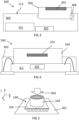
- the sensing element 202 and processing means can be integrated in the same integrated circuit IC2. This configuration can be applied to any other embodiment, not being limited to the embodiment of FIG 2 .
- FIG 2 shows a force sensor 200 including a compact elastomer 204, for example an elastomeric sheet, completely embedding the target piece 201.
- a compact elastomer 204 for example an elastomeric sheet
- the thickness t2 of the flexible piece can be tailored, so as to provide enough cushion to improve sensitivity of the sensing element while at the same time keeping the distance d2 between the target piece 201 and the sensing element 202 not so large that it hinders significantly the signal detection characteristics (such as e.g. signal to noise ratio).
- the target piece 201 may be covered by a shielding layer or it may be embedded within the elastomer 204, specially shielding the target piece 201 from physical contact with external pieces or from potentially corrosive or oxidating environment, also in the case of embedding the target piece 201 in the flexible piece potentially improving compactness.
- FIG 2 also shows that the integrated circuit IC may also integrate the sensing element 102.
- the package can be very compact, as the mold 203 still encapsulates both the sensing element and the processing means, but both in a single integrated circuit, e.g. in a single semiconductor die.
- This embodiment is very compact and has low profile and footprint, due to the combination of the sensing element-processing means integration and the target-elastomer integration.
- the elastomer integrating the target may be applied to any other embodiment, as well as the integrated circuit IC integrating the sensing element can be applied to any other embodiment.
- the sensing element or parts thereof may be integrated in the same semiconductor substrate as the processing means, forming an integrated circuit with both. In other embodiments, only some parts of the sensing element may be integrated in the semiconductor die.
- the sensing element 302 can be placed adjacent to the integrated circuit IC3 with the processing means.
- the signals may be transmitted from the sensing element 302 to the processing means by wirebonds, for example.
- the integrated circuit and the sensing element 302 do not even need to be in physical contact, both of them are however encapsulated in the same mold 303.
- the sensing element may be overlapped by the target.
- the target piece may be centered with the sensing element or, in the case of the embodiment of FIG 3 , the sensing element (and the integrated circuit IC3) may be laid out offset from the center of the target and for example also from the whole flexible piece.
- the force sensor has larger footprint, but potentially lower profile (less height) than other embodiments such as e.g. the embodiment of FIG 1 , in a simple layout of easy manufacture.
- This configuration also reduces risks to damage the circuit with the processing means, because most or all pressure from the contact forces is not transmitted through the flexible piece 304 and mold 303 directly on the integrated circuit IC3, thus protecting the processing means in the integrated circuit IC3.
- FIG 3 also shows a flexible piece 304 partially embedded in the mold 303.
- the mold 303 may be shaped to fit the flexible piece 304, thus reducing the risk of tearing the flexible piece away from the package due to shear forces perpendicular to the compressing forces.
- the mold and the elastomer may be shaped so they interlock, e.g. including interlocking elements 308 such as ribs and slits.
- the flexible piece may be flush with the mold surface, so no adhesive is absolutely required.
- the surface of the flexible piece keeping it fixed in place is smaller than the area of the package where the flexible piece is provided (e.g. it does not extend beyond the package).
- the top projection of the flexible piece may not extend beyond the top projection of the package, thus allowing a compact force sensor with small footprint.
- the top projection may also be understood as the direction following the applied contact force to be measured.
- the top projection of the target is also contained with the area of the IC package.
- the target may be smaller than the IC package, e.g. smaller area and/or smaller volume.
- a small target e.g. small magnet
- the size ratio between the IC and the target piece is 1.5 or more, for example between 1.5 and 3, or even larger than 3.
- the target piece 301 may be partially embedded in the flexible piece 304, for example it may be flush with the flexible piece.
- the force sensor may be configured to provide dual sensing, allowing detecting shear forces, for example shear forces in one direction or two orthogonal directions in the plane perpendicular to the direction of the compressing forces.
- Signals generated by the sensing element in the integrated circuit can be processed into readout signals, which can be output by connections from the integrated circuit to the exterior (e.g. through wires, a frame 106, pins, etc., not pictured in FIG 2 or FIG 3 ).
- the exterior may include a support structure holding the force sensor and conductors for sending the readout signals from the processing unit in the integrated circuit to an external device.
- the support structure is a PCB.
- the present invention is not limited to attachment of the flexible piece to the top surface of the mold of the package.
- the mold of the package may comprise an opening or cavity exposing the interior, e.g. the semiconductor material of the IC substrate, or even the sensing element.
- the IC substrate can receive the flexible piece as shown in FIG 4 .
- the flexible piece may be attached to the semiconductor package, being held in place by the mold, optionally further being attached to the integrated circuit, e.g. to the substrate of the IC.
- the flexible piece may be in physical contact or adhered to the sensing element.
- the mold may only partially cover the IC substrate, leaving space to receive the flexible piece.
- the target piece is completely supported or embedded by the flexible piece.
- the target piece is smaller than the flexible piece, for example the target piece may be completely contained in the top view or outline of the flexible piece.
- the target is smaller than the package, so the target is contained in the outline of the IC package, allows to detect shear stress easily. It is advantageous that the magnet is smaller than a ratio of the outline.
- the side of the flexible piece e.g. the largest side, e.g. the diameter if the top view is a circumference
- the largest dimension of the target piece may have a ratio of 1.5, or 2, or 3.
- the exemplary force sensor on which simulations were made as shown in FIG 6 to FIG 9 had a target with a diametral dimension of 1.5mm and a side of the outline of 5mm (ratio 3).
- Shear stress can advantageously be resolved with accuracy, as the field changes noticeably, when the outline (e.g. top view) of the magnet is smaller than the outline (e.g. top view or top surface) of the IC package, in particular with ratios equal to or larger than 1.5, e.g. between 1.5 and 3. This applies to both magnetic and inductive sensing (thus, for magnetic targets and inductive targets).
- the shear stress detection is not limited to magnetic detection systems.
- the skilled person can suitably adapt other systems for detection of shear stress.
- two induction coils per axis may be located around the neutral position of the target. At the neutral position, the signals are balanced. When the inductive target moves right or left, the signal (or a ratio of signals) will be unbalanced and a displacement can be detected. When the target moves up or down, the intensity changes.
- the senor can measure compression (displacement in Z direction, see FIG 1 or FIG 4 ). In some embodiments, the sensor can measure shear stress (displacement in the X/Y directions, see FIG 1 or FIG 4 ). In some embodiments, it can measure displacement in the three directions.
- the senor can eventually also measure torsion, not only translation of the magnet in the x/y/z directions but also rotation of the magnet (for example defined by two angles).
- This can be implemented, for example, with a 3D sensor, for example a 3D Hall sensor made of a combination of horizontal Hall elements (sensitive to motions with direction perpendicular to the IC) and vertical Hall elements (sensitive to motions with direction parallel to the IC).
- the implementation can provide a 3D sensor made of horizontal Hall elements and magnetic concentrators disposed so as to concentrate components of the magnetic field in different directions separately.
- magneto-resistive elements such as AMR, or GMR, or TMR can be used.
- Bz Any component or combination of components (Bx, By, Bz) can be used to detect the displacement in different directions.
- Bz is not bound to measurement solely of compression, and Bx,By is not bound to shear stress measurement.
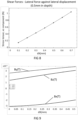
- FIG 6 to FIG 9 show stress tensor variation and simulations of compression and shear tests of a force sensor which may be, for example, a 6x6 mm QFN IC package with one magnetic probe (although the present invention may include more probes) on a support and may receive on the top surface a piece of elastomer with a height of 2.5 mm and a top area of 5x5 mm, where the IC package completely surrounds the elastomer.
- the target piece may be a magnetic disk of 1.5 mm diameter and 0.5 mm thickness, flush with the surface of the elastomer opposite to the surface attached to the IC package, and in the center of the top projection of the elastomer.
- the probe itself may be offset with the axis of the magnet, for example it may be at a distance in the order of 1 mm from the axis.
- the sensing element or sensing elements may be offset with the axis crossing the center of the target piece up to 2 mm or less.
- the target may be at the same distance of both while not under a contact force.
- the senor may include one sensing element, which may be centered or not with respect to the target piece. In those embodiments where it is not centered, the sensing element may not overlap with the target piece in the top projection.
- the probe is located outside the outer periphery of the top projection of the target piece (magnet). For multiple probes, in some embodiments they may be laid out symmetrically around the axis of the target piece (e.g. on the vertices of a square, if there are four sensing elements, where the axis of the target piece passes through the center of the square).
- FIG 6 shows the normal force (in Newtons) as function of the compression displacement (in mm) for the exemplary force sensor described above.
- the simulation of the magnetic field variation with the position, using one probe, is shown in FIG 7 , for the three dimensions (X, Y, Z).
- FIG 8 shows the shear force (in Newtons) as function of the compression displacement (in mm) for the same force.
- the simulation of the magnetic field variation with the position, using one off-centered probe, is shown in FIG 9 , for the three dimensions (X, Y, Z).
- the present invention provides a contact sensor assembly including the force sensor of the first aspect, and further including a support structure for the force sensor.
- the support structure may provide transfer of signals from the force sensor to an output or data storage or the like.
- Such output may be a user interface such as a screen.
- the output or data storage may also be part of the assembly.
- FIG 5 shows a perspective view of an exemplary embodiment of the assembly of the present invention.
- the force sensor 100 is provided on the support structure 401, and the top surface of the IC package 105 completely surrounds the flexible piece 104 of the force sensor 100, so the flexible piece 104 does not extend over the support structure 401, as it is limited by the top surface 113 of the mold 103 of the package (as shown in FIG 1 ).
- the support structure 401 may comprise connections and conductive paths such as conductive tracks, for rerouting signals provided by the force sensor 100 to a device for storing and/or displaying data.
- the integrated circuit IC may receive signals from the sensing element 102, representative of the motion of the target 101 (see FIG 1 ) caused by a contact force following the compression direction 402, on the flexible piece supporting said target.
- the integrated circuit IC can be configured to process these signals and provide readout signals, which are rerouted to a display, data storage or the like through conductive tracks in the PCB being the support structure 401.
- the force sensor may be connected to conductive paths in the support structure via contacts through the package of the sensor to the integrated circuit.
- the contact sensor assembly is not limited by a PCB being the support structure, and the assembly may be a PCB-less assembly.
- the chip package may be contacted (e.g. soldered) to electrical leads and clipped or glued or 'heat-stacked' to a plastic assembly.
- the present invention provides a method for manufacturing the force sensor of the first aspect of the present invention.
- the method can be divided in three main manufacturing steps: manufacturing the flexible piece, manufacturing the IC package, and providing the flexible piece on the IC package.
- FIG 10 shows a simplified scheme for manufacturing the force sensor.
- the method includes providing S10 a flexible piece including the target piece, providing circuitry S20 with sensing means and processing means (such as a sensing element and an integrated processor), packaging S30 the circuitry and finally providing the force sensor by attaching S40 the flexible piece including the target piece to the IC package.
- Providing S10 the flexible piece including the target piece may comprise integrating or embedding S14 the target piece with the flexible piece, for example by molding the flexible piece with the target piece inside the flexible material, thus completely embedding the target piece inside the flexible piece.
- Embedding S14 the target piece inside the flexible piece allows protection of the target against the environment and against damage from contact with the object to be grasped, but the thickness between the contact surface of the flexible piece and the target should not be so large the contact forces are dampened, thus reducing sensibility.
- the present invention is not limited thereto, and the method may include separately providing S11 the flexible piece, providing S12 the target piece, and then attaching S13 the target piece to the flexible piece, which is a simple process.
- This attachment can be done with adhesive, for example on the surface of the flexible piece, or without adhesive, by fitting the target piece inside an open hole in the flexible piece.
- the target piece may be a metal trace deposited on the surface of the elastomer, for example.
- the target piece may be only partially embedded, where only a part of the target piece is external (e.g. a surface of the target) while the rest of the target piece is surrounded by the flexible piece.
- the target piece may be further covered by a shielding layer to protect it from damages from the contact with external pieces and/or environment.
- the flexibility of the piece can be chosen by choosing suitable materials, and the thickness of the flexible piece between the target and the surface to be attached to the IC package can be optimized taking into account the range of displacement (deformation) under contact forces, which improves with the increasing thickness, and the sensitivity of the sensing element, which drops with distance between sensing element and the target piece. Additionally, a low profile is preferred.
- Providing the target may comprise providing a suitably shaped magnet or metal piece, e.g. sheet, with a resistivity such that it is suitable for inductance sensing.
- Providing the flexible piece S10, S11, S14 may comprise providing an elastomeric polymer, such as silicone rubber. In some embodiments it may comprise molding, e.g. injection molding the piece in a predetermined shape and size, e.g. including a surface for attaching to a surface of the IC package without surpassing the boundaries of said surface of the IC package.
- Providing S20 an IC with a processor and the sensing element may comprise separately providing S21 an integrated circuit with a processor and providing S21 a sensing element, and electrically connecting them, so the signals from the sensing element can be sent to the integrated circuit.
- it may further comprise attaching them together, for example the sensing element may be placed on the side of the IC facing the target. In some embodiments, they may be laid out adjacent to each other, for example on a common support or frame.
- the sensing element may be provided in the integrated circuit; in other words, the method may comprise providing S23 the processing means and the sensing element integrated in the same integrated circuit IC.
- the method comprises packaging S30 the sensing element and the processing means in the integrated circuit together, for example by overmolding both elements, thus providing a packaged integrated circuit with a sensing element and processing means for processing signals generated by the sensing element.
- Packaging S30 the IC and the sensing element may comprise providing an IC package with a planar profile, where the largest surfaces are opposite to each other.
- the packaging may be done by orienting the sensing element so it faces one of these largest external surfaces of the IC package, which is known in the frame of the present invention as the 'top surface' 113 as explained with reference to FIG 1 . For example, it may be closest to the top surface.
- packaging S30 may comprise providing an IC package by overmolding the IC and sensing element while leaving a cavity for receiving the flexible piece.
- the IC and/or sensing element may be only partially overmolded, so the flexible piece can be attached to the IC or sensing element of the IC package.
- the flexible piece and the IC package are attached to each other S40.
- the attachment of the flexible piece is done so as to allow the maximum displacement of the target piece relative to the IC package upon contact.
- the IC package upon attachment the IC package is oriented so the sensing element faces the target, e.g. is closest to the target, e.g. is closest to the top surface where the flexible piece is provided.
- the attachment may be done with no adhesive, by interlocking elements provided in the IC package upon molding and on the flexible piece, or by addition of an adhesive layer.
- the attachment may be done directly on the IC or sensing element by fitting the flexible piece into a cavity provided in the mold of the IC package, as explained above. In any case, no spacer is required between the IC package and the flexible piece.
- the attachment is done S40 so that the surface of the flexible piece is attached only to the surface of the IC package.
- the flexible piece may not be attached to any substrate outside the IC package.
- the shape of the elastomer and its positioning results in that the top projection of the flexible piece is confined to the area of the top surface of the package, reducing sensor footprint.
- the attachment may be done so that the axis of the target piece passes through a sensing element so the sensing element will be centered. In other embodiments, the attachment may be done so that the axis does not cross any sensing element, where the sensing element is at a distance of 2 mm or less from the axis.
- the force sensor may be attached to a substrate such as a PCB, thus obtaining a force sensor assembly.
- the attachment may include soldering the IC package to the PCB, if present. This can be done for example after or before attaching the flexible piece on the IC package.
- the method may be adapted for the production of a sensor in accordance with any of the embodiments of the first aspects.
- the target piece and the IC package may be provided so the target piece is at least 1.5 times smaller in at least one dimension than the IC package, for example 3 times smaller, or even smaller, the at least one dimension being measured as from the top projection of the force sensor.
Landscapes
- Physics & Mathematics (AREA)
- General Physics & Mathematics (AREA)
- Engineering & Computer Science (AREA)
- Condensed Matter Physics & Semiconductors (AREA)
- Electromagnetism (AREA)
- Human Computer Interaction (AREA)
- Robotics (AREA)
- Mechanical Engineering (AREA)
- Force Measurement Appropriate To Specific Purposes (AREA)
- Pressure Sensors (AREA)
Priority Applications (1)
| Application Number | Priority Date | Filing Date | Title |
|---|---|---|---|
| EP25157905.8A EP4530586A3 (de) | 2021-06-28 | 2021-06-28 | Kraftsensor mit target auf halbleitergehäuse |
Applications Claiming Priority (2)
| Application Number | Priority Date | Filing Date | Title |
|---|---|---|---|
| EP21182116.0A EP4113085B1 (de) | 2021-06-28 | 2021-06-28 | Kraftsensor mit ziel auf einem halbleitergehäuse |
| EP25157905.8A EP4530586A3 (de) | 2021-06-28 | 2021-06-28 | Kraftsensor mit target auf halbleitergehäuse |
Related Parent Applications (2)
| Application Number | Title | Priority Date | Filing Date |
|---|---|---|---|
| EP21182116.0A Division EP4113085B1 (de) | 2021-06-28 | 2021-06-28 | Kraftsensor mit ziel auf einem halbleitergehäuse |
| EP21182116.0A Division-Into EP4113085B1 (de) | 2021-06-28 | 2021-06-28 | Kraftsensor mit ziel auf einem halbleitergehäuse |
Publications (2)
| Publication Number | Publication Date |
|---|---|
| EP4530586A2 true EP4530586A2 (de) | 2025-04-02 |
| EP4530586A3 EP4530586A3 (de) | 2025-06-18 |
Family
ID=76695620
Family Applications (3)
| Application Number | Title | Priority Date | Filing Date |
|---|---|---|---|
| EP21182116.0A Active EP4113085B1 (de) | 2021-06-28 | 2021-06-28 | Kraftsensor mit ziel auf einem halbleitergehäuse |
| EP25157905.8A Pending EP4530586A3 (de) | 2021-06-28 | 2021-06-28 | Kraftsensor mit target auf halbleitergehäuse |
| EP21206815.9A Pending EP4113086A1 (de) | 2021-06-28 | 2021-11-05 | Kraftmesswaage mit zielteil |
Family Applications Before (1)
| Application Number | Title | Priority Date | Filing Date |
|---|---|---|---|
| EP21182116.0A Active EP4113085B1 (de) | 2021-06-28 | 2021-06-28 | Kraftsensor mit ziel auf einem halbleitergehäuse |
Family Applications After (1)
| Application Number | Title | Priority Date | Filing Date |
|---|---|---|---|
| EP21206815.9A Pending EP4113086A1 (de) | 2021-06-28 | 2021-11-05 | Kraftmesswaage mit zielteil |
Country Status (6)
| Country | Link |
|---|---|
| US (3) | US12287233B2 (de) |
| EP (3) | EP4113085B1 (de) |
| JP (1) | JP2024526586A (de) |
| KR (1) | KR102928589B1 (de) |
| CN (1) | CN117597570A (de) |
| WO (1) | WO2023275010A1 (de) |
Families Citing this family (5)
| Publication number | Priority date | Publication date | Assignee | Title |
|---|---|---|---|---|
| EP4113085B1 (de) * | 2021-06-28 | 2025-03-26 | Melexis Technologies SA | Kraftsensor mit ziel auf einem halbleitergehäuse |
| JP2023092112A (ja) * | 2021-12-21 | 2023-07-03 | 株式会社ジャパンディスプレイ | 圧力センサの校正方法 |
| EP4339573A1 (de) * | 2022-09-15 | 2024-03-20 | Melexis Technologies SA | Anordnung eines integrierten soft-kraft-sensors |
| CN119880235B (zh) * | 2025-01-20 | 2025-10-17 | 河北工业大学 | 一种基于磁性薄膜的三维力-温度双模态触觉传感器 |
| CN120084474B (zh) * | 2025-02-21 | 2025-11-18 | 东南大学 | 基于径向磁化的自解耦三维力多模态传感装置、系统及方法 |
Citations (1)
| Publication number | Priority date | Publication date | Assignee | Title |
|---|---|---|---|---|
| US20210018574A1 (en) | 2018-03-24 | 2021-01-21 | Melexis Technologies Sa | Magnetic sensor component and assembly |
Family Cites Families (43)
| Publication number | Priority date | Publication date | Assignee | Title |
|---|---|---|---|---|
| US5000274A (en) * | 1989-01-19 | 1991-03-19 | K-Tron International, Inc. | Weight sensor |
| JP2673849B2 (ja) * | 1992-04-09 | 1997-11-05 | 畑村 洋太郎 | 力検出手段付き直線運動用案内装置 |
| JPH06151892A (ja) * | 1992-11-04 | 1994-05-31 | Fujikura Ltd | 集積化半導体圧力センサ |
| JPH06252421A (ja) * | 1993-02-26 | 1994-09-09 | Fujikura Ltd | 集積化半導体圧力センサ |
| JP3131642B2 (ja) * | 1994-09-14 | 2001-02-05 | 日本電子工業株式会社 | 応力複合化センサ及びこれを用いた構造体の応力測定装置 |
| JPH08110351A (ja) * | 1994-10-12 | 1996-04-30 | Nippondenso Co Ltd | 半導体力学センサ装置 |
| US6026694A (en) * | 1998-03-30 | 2000-02-22 | Serena Industries Incorporated | Linear force sensing device |
| US7047826B2 (en) * | 1999-05-07 | 2006-05-23 | Northwestern University | Force sensors |
| JP4559706B2 (ja) * | 2001-04-19 | 2010-10-13 | 旭化成エレクトロニクス株式会社 | ポインティングデバイス |
| US7536218B2 (en) * | 2005-07-15 | 2009-05-19 | Biosense Webster, Inc. | Hybrid magnetic-based and impedance-based position sensing |
| JP4165589B2 (ja) * | 2006-08-09 | 2008-10-15 | ソニー株式会社 | 検出装置およびその検出方法 |
| JP5003336B2 (ja) * | 2007-07-31 | 2012-08-15 | ソニー株式会社 | 検出装置、ロボット装置、および入力装置 |
| ATE490051T1 (de) * | 2007-10-22 | 2010-12-15 | Eads Deutschland Gmbh | Werkzeughalter und verfahren zur erzeugung einer inkrementellen folie damit |
| JP2009229453A (ja) * | 2008-02-28 | 2009-10-08 | Seiko Epson Corp | 圧力検出装置及び圧力検出方法 |
| JP2009295301A (ja) * | 2008-06-02 | 2009-12-17 | Tokai Rika Co Ltd | 複合スイッチレバー装置及びその磁気検出部の構造 |
| JP2010199148A (ja) * | 2009-02-23 | 2010-09-09 | Fujikura Ltd | 半導体センサデバイス及びその製造方法、パッケージ及びその製造方法、モジュール及びその製造方法、並びに電子機器 |
| US8047085B2 (en) * | 2009-05-27 | 2011-11-01 | Corning Incorporated | Force monitoring methods and apparatus |
| JP5500957B2 (ja) * | 2009-11-26 | 2014-05-21 | キヤノン株式会社 | 磁気式力覚センサ |
| DE102010026516B4 (de) * | 2010-07-08 | 2013-04-11 | Austriamicrosystems Ag | Feder für einen Drucktaster, Federanordnung und Tasteranordnung |
| JP5609613B2 (ja) * | 2010-12-14 | 2014-10-22 | 株式会社村田製作所 | 衝撃及び音響センサ |
| DE102012101081B4 (de) * | 2012-02-09 | 2023-08-31 | Univerza V Ljubljani Fakulteta Za Elektrotehniko | Verfahren und Vorrichtung zur Krafterfassung |
| JP6097081B2 (ja) * | 2013-01-15 | 2017-03-15 | 東洋ゴム工業株式会社 | センサとその製造方法 |
| ITMI20130482A1 (it) | 2013-03-29 | 2014-09-30 | St Microelectronics Srl | Dispositivo elettronico integrato per il monitoraggio di pressione all'interno di una struttura solida |
| US10145908B2 (en) * | 2013-07-19 | 2018-12-04 | Allegro Microsystems, Llc | Method and apparatus for magnetic sensor producing a changing magnetic field |
| EP3111180A1 (de) * | 2014-02-26 | 2017-01-04 | 3M Innovative Properties Company | Auf kraft reagierende induktoren für kraftsensoren |
| EP3229634A1 (de) * | 2014-12-10 | 2017-10-18 | HCI Viocare Technologies Ltd. | Kraftmesser |
| US9766142B1 (en) * | 2015-03-20 | 2017-09-19 | Cory S. Hague | Magnetic force sensor systems and methods |
| JP6491087B2 (ja) * | 2015-12-22 | 2019-03-27 | 株式会社豊田中央研究所 | センサ装置 |
| JP6817035B2 (ja) * | 2016-02-01 | 2021-01-20 | アルプスアルパイン株式会社 | 電子装置およびその製造方法 |
| DE102016103325B4 (de) * | 2016-02-25 | 2025-03-20 | Infineon Technologies Ag | Magnetischer Winkelpositionssensor |
| US10054503B2 (en) * | 2016-03-11 | 2018-08-21 | Microsoft Technology Licensing, Llc | Force sensor |
| EP3223429A1 (de) * | 2016-03-24 | 2017-09-27 | The Swatch Group Research and Development Ltd. | Kraftsensor, insbesondere für eine berührungsempfindliche platte |
| JP6703728B2 (ja) * | 2016-07-11 | 2020-06-03 | 学校法人早稲田大学 | 近接触覚センサ |
| EP3517897B1 (de) * | 2018-01-25 | 2020-10-28 | Melexis Technologies SA | Positionserfassungsvorrichtung |
| US11300397B2 (en) * | 2019-03-20 | 2022-04-12 | Massachusetts Institute Of Technology | Compliant force sensing system |
| CN111618912A (zh) * | 2020-06-28 | 2020-09-04 | 威海华菱光电股份有限公司 | 触觉传感器 |
| CN112067170A (zh) * | 2020-09-14 | 2020-12-11 | 哈尔滨工业大学 | 一种基于变压器原理的柔性触觉传感器及其柔性触觉检测系统 |
| EP4113085B1 (de) * | 2021-06-28 | 2025-03-26 | Melexis Technologies SA | Kraftsensor mit ziel auf einem halbleitergehäuse |
| CN117501082A (zh) * | 2021-06-29 | 2024-02-02 | 新加坡国立大学 | 力传感器和包含力传感器的设备 |
| US11920992B2 (en) * | 2021-07-20 | 2024-03-05 | Toyota Research Institute, Inc. | Deformable sensors and methods using magnetic repulsion for modifying run-time membrane stiffness |
| US11740065B2 (en) * | 2021-08-06 | 2023-08-29 | Toyota Research Institute, Inc. | Deformable sensors and methods for modifying run-time membrane stiffness using magnetic attraction |
| EP4148395B1 (de) * | 2021-09-09 | 2025-01-01 | Melexis Technologies SA | Magnetische sensorvorrichtungen, systeme und verfahren sowie ein kraftsensor |
| EP4187262A1 (de) * | 2021-11-25 | 2023-05-31 | Melexis Technologies SA | Beschichtungstechnikbasierte spannungsreduktionsschicht |
-
2021
- 2021-06-28 EP EP21182116.0A patent/EP4113085B1/de active Active
- 2021-06-28 EP EP25157905.8A patent/EP4530586A3/de active Pending
- 2021-11-05 EP EP21206815.9A patent/EP4113086A1/de active Pending
-
2022
- 2022-06-27 US US17/850,509 patent/US12287233B2/en active Active
- 2022-06-27 US US17/850,566 patent/US12339159B2/en active Active
- 2022-06-28 JP JP2023579527A patent/JP2024526586A/ja active Pending
- 2022-06-28 KR KR1020237043270A patent/KR102928589B1/ko active Active
- 2022-06-28 CN CN202280045893.4A patent/CN117597570A/zh active Pending
- 2022-06-28 WO PCT/EP2022/067664 patent/WO2023275010A1/en not_active Ceased
-
2025
- 2025-05-22 US US19/216,365 patent/US20250283751A1/en active Pending
Patent Citations (1)
| Publication number | Priority date | Publication date | Assignee | Title |
|---|---|---|---|---|
| US20210018574A1 (en) | 2018-03-24 | 2021-01-21 | Melexis Technologies Sa | Magnetic sensor component and assembly |
Also Published As
| Publication number | Publication date |
|---|---|
| US20250283751A1 (en) | 2025-09-11 |
| CN117597570A (zh) | 2024-02-23 |
| EP4113085A1 (de) | 2023-01-04 |
| EP4530586A3 (de) | 2025-06-18 |
| KR102928589B1 (ko) | 2026-02-19 |
| JP2024526586A (ja) | 2024-07-19 |
| EP4113086A1 (de) | 2023-01-04 |
| US12339159B2 (en) | 2025-06-24 |
| KR20240024084A (ko) | 2024-02-23 |
| WO2023275010A1 (en) | 2023-01-05 |
| US12287233B2 (en) | 2025-04-29 |
| US20220412816A1 (en) | 2022-12-29 |
| EP4113085B1 (de) | 2025-03-26 |
| US20220412791A1 (en) | 2022-12-29 |
Similar Documents
| Publication | Publication Date | Title |
|---|---|---|
| US12339159B2 (en) | Force sensor with target on semiconductor package | |
| JP5851841B2 (ja) | 磁場センサおよび磁場センサを製造する方法 | |
| US9196437B2 (en) | Operation input apparatus and operation input detection apparatus | |
| KR101953643B1 (ko) | 스플릿 리드 프레임을 갖는 집적 회로 패키지 | |
| US8089276B2 (en) | Magnetic field sensor assembly | |
| CN118884312B (zh) | 一种磁场传感器及基于磁场传感器检测磁场分量的方法 | |
| KR20160128996A (ko) | 자기 탄성 센서 | |
| EP2339362A1 (de) | Magnetsensormodul und Bolzenpositionsdetektor | |
| CN117484552A (zh) | 基于磁感应力觉自解耦的多功能电子皮肤及其制备方法 | |
| CN114354025B (zh) | 一种测力装置及末端执行器 | |
| EP4303551A1 (de) | Sensoranordnung mit weichkraftsensoren | |
| KR20250099961A (ko) | 2차원 압력 센서 및 2차원 압력 센서 어레이 | |
| WO2025141097A1 (en) | Methods and devices for measuring a mechanical force | |
| EP4286812A1 (de) | Weicher kraftsensor | |
| WO2023275006A1 (en) | Force sensing scale with target | |
| JPH02284082A (ja) | ホール効果型センサ装置 | |
| EP4339573A1 (de) | Anordnung eines integrierten soft-kraft-sensors | |
| CN115667964A (zh) | 磁传感器封装 | |
| JPH0727785A (ja) | 加速度センサー |
Legal Events
| Date | Code | Title | Description |
|---|---|---|---|
| PUAI | Public reference made under article 153(3) epc to a published international application that has entered the european phase |
Free format text: ORIGINAL CODE: 0009012 |
|
| STAA | Information on the status of an ep patent application or granted ep patent |
Free format text: STATUS: THE APPLICATION HAS BEEN PUBLISHED |
|
| AC | Divisional application: reference to earlier application |
Ref document number: 4113085 Country of ref document: EP Kind code of ref document: P |
|
| AK | Designated contracting states |
Kind code of ref document: A2 Designated state(s): AL AT BE BG CH CY CZ DE DK EE ES FI FR GB GR HR HU IE IS IT LI LT LU LV MC MK MT NL NO PL PT RO RS SE SI SK SM TR |
|
| REG | Reference to a national code |
Ref country code: DE Ref legal event code: R079 Free format text: PREVIOUS MAIN CLASS: G01G0019520000 Ipc: G01L0001120000 |
|
| PUAL | Search report despatched |
Free format text: ORIGINAL CODE: 0009013 |
|
| AK | Designated contracting states |
Kind code of ref document: A3 Designated state(s): AL AT BE BG CH CY CZ DE DK EE ES FI FR GB GR HR HU IE IS IT LI LT LU LV MC MK MT NL NO PL PT RO RS SE SI SK SM TR |
|
| RIC1 | Information provided on ipc code assigned before grant |
Ipc: B25J 13/08 20060101ALI20250512BHEP Ipc: G01L 5/22 20060101ALI20250512BHEP Ipc: G01L 5/169 20200101ALI20250512BHEP Ipc: G01L 5/164 20200101ALI20250512BHEP Ipc: G01L 1/14 20060101ALI20250512BHEP Ipc: G01L 1/12 20060101AFI20250512BHEP |
|
| STAA | Information on the status of an ep patent application or granted ep patent |
Free format text: STATUS: REQUEST FOR EXAMINATION WAS MADE |
|
| 17P | Request for examination filed |
Effective date: 20251218 |
|
| STAA | Information on the status of an ep patent application or granted ep patent |
Free format text: STATUS: EXAMINATION IS IN PROGRESS |