EP4530476A2 - Klimaanlage - Google Patents
Klimaanlage Download PDFInfo
- Publication number
- EP4530476A2 EP4530476A2 EP25152288.4A EP25152288A EP4530476A2 EP 4530476 A2 EP4530476 A2 EP 4530476A2 EP 25152288 A EP25152288 A EP 25152288A EP 4530476 A2 EP4530476 A2 EP 4530476A2
- Authority
- EP
- European Patent Office
- Prior art keywords
- flow fan
- cross flow
- end protrusion
- air conditioner
- heat exchanger
- Prior art date
- Legal status (The legal status is an assumption and is not a legal conclusion. Google has not performed a legal analysis and makes no representation as to the accuracy of the status listed.)
- Pending
Links
Images


Classifications
-
- F—MECHANICAL ENGINEERING; LIGHTING; HEATING; WEAPONS; BLASTING
- F24—HEATING; RANGES; VENTILATING
- F24F—AIR-CONDITIONING; AIR-HUMIDIFICATION; VENTILATION; USE OF AIR CURRENTS FOR SCREENING
- F24F1/00—Room units for air-conditioning, e.g. separate or self-contained units or units receiving primary air from a central station
- F24F1/0007—Indoor units, e.g. fan coil units
- F24F1/0018—Indoor units, e.g. fan coil units characterised by fans
- F24F1/0025—Cross-flow or tangential fans
-
- F—MECHANICAL ENGINEERING; LIGHTING; HEATING; WEAPONS; BLASTING
- F04—POSITIVE - DISPLACEMENT MACHINES FOR LIQUIDS; PUMPS FOR LIQUIDS OR ELASTIC FLUIDS
- F04D—NON-POSITIVE-DISPLACEMENT PUMPS
- F04D17/00—Radial-flow pumps, e.g. centrifugal pumps; Helico-centrifugal pumps
- F04D17/02—Radial-flow pumps, e.g. centrifugal pumps; Helico-centrifugal pumps having non-centrifugal stages, e.g. centripetal
- F04D17/04—Radial-flow pumps, e.g. centrifugal pumps; Helico-centrifugal pumps having non-centrifugal stages, e.g. centripetal of transverse-flow type
-
- F—MECHANICAL ENGINEERING; LIGHTING; HEATING; WEAPONS; BLASTING
- F04—POSITIVE - DISPLACEMENT MACHINES FOR LIQUIDS; PUMPS FOR LIQUIDS OR ELASTIC FLUIDS
- F04D—NON-POSITIVE-DISPLACEMENT PUMPS
- F04D29/00—Details, component parts, or accessories
- F04D29/40—Casings; Connections of working fluid
- F04D29/42—Casings; Connections of working fluid for radial or helico-centrifugal pumps
- F04D29/44—Fluid-guiding means, e.g. diffusers
- F04D29/441—Fluid-guiding means, e.g. diffusers especially adapted for elastic fluid pumps
-
- F—MECHANICAL ENGINEERING; LIGHTING; HEATING; WEAPONS; BLASTING
- F04—POSITIVE - DISPLACEMENT MACHINES FOR LIQUIDS; PUMPS FOR LIQUIDS OR ELASTIC FLUIDS
- F04D—NON-POSITIVE-DISPLACEMENT PUMPS
- F04D29/00—Details, component parts, or accessories
- F04D29/66—Combating cavitation, whirls, noise, vibration or the like; Balancing
- F04D29/661—Combating cavitation, whirls, noise, vibration or the like; Balancing especially adapted for elastic fluid pumps
- F04D29/663—Sound attenuation
-
- F—MECHANICAL ENGINEERING; LIGHTING; HEATING; WEAPONS; BLASTING
- F24—HEATING; RANGES; VENTILATING
- F24F—AIR-CONDITIONING; AIR-HUMIDIFICATION; VENTILATION; USE OF AIR CURRENTS FOR SCREENING
- F24F1/00—Room units for air-conditioning, e.g. separate or self-contained units or units receiving primary air from a central station
- F24F1/0007—Indoor units, e.g. fan coil units
- F24F1/0043—Indoor units, e.g. fan coil units characterised by mounting arrangements
- F24F1/0057—Indoor units, e.g. fan coil units characterised by mounting arrangements mounted in or on a wall
-
- F—MECHANICAL ENGINEERING; LIGHTING; HEATING; WEAPONS; BLASTING
- F24—HEATING; RANGES; VENTILATING
- F24F—AIR-CONDITIONING; AIR-HUMIDIFICATION; VENTILATION; USE OF AIR CURRENTS FOR SCREENING
- F24F13/00—Details common to, or for air-conditioning, air-humidification, ventilation or use of air currents for screening
- F24F13/20—Casings or covers
-
- F—MECHANICAL ENGINEERING; LIGHTING; HEATING; WEAPONS; BLASTING
- F24—HEATING; RANGES; VENTILATING
- F24F—AIR-CONDITIONING; AIR-HUMIDIFICATION; VENTILATION; USE OF AIR CURRENTS FOR SCREENING
- F24F13/00—Details common to, or for air-conditioning, air-humidification, ventilation or use of air currents for screening
- F24F13/24—Means for preventing or suppressing noise
-
- F—MECHANICAL ENGINEERING; LIGHTING; HEATING; WEAPONS; BLASTING
- F05—INDEXING SCHEMES RELATING TO ENGINES OR PUMPS IN VARIOUS SUBCLASSES OF CLASSES F01-F04
- F05D—INDEXING SCHEME FOR ASPECTS RELATING TO NON-POSITIVE-DISPLACEMENT MACHINES OR ENGINES, GAS-TURBINES OR JET-PROPULSION PLANTS
- F05D2250/00—Geometry
- F05D2250/50—Inlet or outlet
- F05D2250/51—Inlet
Definitions
- the present disclosure mainly relates to an air conditioner for household.
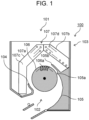
- an air conditioner includes, within a housing, a cross flow fan having a plurality of blades, a stabilizer, a rear guider, and a heat exchanger.
- the heat exchanger includes a front heat exchanger disposed on a front side of the cross flow fan and a rear heat exchanger disposed on a rear side of the cross flow fan.
- Such an air conditioner is configured to suck air from a top surface side of the housing of the air conditioner, exchange heat between the sucked air and a refrigerant flowing inside the heat exchanger, and blow out the air from a bottom surface side of the housing. Accordingly, indoor air conditioning is performed.
- the air conditioner includes an air blowing passage that allows an air outlet and a suction port to communicate with each other.
- the air conditioner includes a cross flow fan, a rear guider, a stabilizer, a front heat exchanger, and a rear heat exchanger within the air blowing passage.
- the cross flow fan includes a plurality of blades.
- the rear guider includes a proximity portion that approach to face the cross flow fan and is separated from the cross flow fan by a predetermined dimension, and an upper end protrusion that further extends from the proximity portion toward an upper side of the rear heat exchanger.
- the front heat exchanger is disposed in front of the cross flow fan, and the rear heat exchanger is disposed behind the cross flow fan.
- the present disclosure provides an air conditioner that rectifies an airflow flowing into a cross flow fan and improves air blowing performance.
- An air conditioner includes a cross flow fan, a stabilizer, a rear guider, a front heat exchanger disposed at a front side of the cross flow fan, and a rear heat exchanger disposed at a rear side of the cross flow fan.
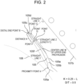
- the rear guider includes a proximity portion facing the cross flow fan and disposed to be in vicinity of the cross flow fan at a predetermined distance, and an upper end protrusion extending upward from the proximity portion.
- the upper end protrusion of the rear guider has an arcuate portion that circumscribes straight line X perpendicular to a downstream surface of the rear heat exchanger.
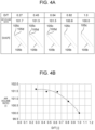
- distal end point B When a contact point between straight line X and the arcuate portion is defined as distal end point B, distal end point B is positioned at a side of the cross flow fan with respect to a center line of the upper end protrusion, and when a diameter of the arcuate portion is defined as D and a thickness of the upper end protrusion is defined as T, D/T ⁇ 0.6 is satisfied.
- the air conditioner of the present disclosure can improve the air blowing performance by improving the turbulence of the airflow flowing into the cross flow fan.
- Fig. 6 is a longitudinal sectional view of air conditioner 1 according to PTL 1.
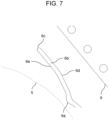
- Fig. 7 is a diagram illustrating a longitudinal sectional configuration near upper end protrusion 6b of air conditioner 1.
- Fig. 8 is a flowchart illustrating a flow of air near upper end protrusion 6b of air conditioner 1.
Landscapes
- Engineering & Computer Science (AREA)
- Mechanical Engineering (AREA)
- General Engineering & Computer Science (AREA)
- Chemical & Material Sciences (AREA)
- Combustion & Propulsion (AREA)
- Air-Conditioning Room Units, And Self-Contained Units In General (AREA)
- Structures Of Non-Positive Displacement Pumps (AREA)
Applications Claiming Priority (3)
| Application Number | Priority Date | Filing Date | Title |
|---|---|---|---|
| JP2022044828 | 2022-03-22 | ||
| PCT/JP2023/009491 WO2023182025A1 (ja) | 2022-03-22 | 2023-03-13 | 空気調和機 |
| EP23774622.7A EP4498014A4 (de) | 2022-03-22 | 2023-03-13 | Klimaanlage |
Related Parent Applications (2)
| Application Number | Title | Priority Date | Filing Date |
|---|---|---|---|
| EP23774622.7A Division EP4498014A4 (de) | 2022-03-22 | 2023-03-13 | Klimaanlage |
| EP23774622.7A Division-Into EP4498014A4 (de) | 2022-03-22 | 2023-03-13 | Klimaanlage |
Publications (2)
| Publication Number | Publication Date |
|---|---|
| EP4530476A2 true EP4530476A2 (de) | 2025-04-02 |
| EP4530476A3 EP4530476A3 (de) | 2025-06-25 |
Family
ID=88101407
Family Applications (2)
| Application Number | Title | Priority Date | Filing Date |
|---|---|---|---|
| EP25152288.4A Pending EP4530476A3 (de) | 2022-03-22 | 2023-03-13 | Klimaanlage |
| EP23774622.7A Pending EP4498014A4 (de) | 2022-03-22 | 2023-03-13 | Klimaanlage |
Family Applications After (1)
| Application Number | Title | Priority Date | Filing Date |
|---|---|---|---|
| EP23774622.7A Pending EP4498014A4 (de) | 2022-03-22 | 2023-03-13 | Klimaanlage |
Country Status (4)
| Country | Link |
|---|---|
| EP (2) | EP4530476A3 (de) |
| JP (1) | JPWO2023182025A1 (de) |
| CN (1) | CN118475798A (de) |
| WO (1) | WO2023182025A1 (de) |
Citations (1)
| Publication number | Priority date | Publication date | Assignee | Title |
|---|---|---|---|---|
| JP2001124362A (ja) | 1999-10-27 | 2001-05-11 | Matsushita Electric Ind Co Ltd | 横断流送風装置 |
Family Cites Families (6)
| Publication number | Priority date | Publication date | Assignee | Title |
|---|---|---|---|---|
| JP3326576B2 (ja) * | 1994-08-25 | 2002-09-24 | 松下電器産業株式会社 | 空気調和機の室内ユニット |
| JP4510172B2 (ja) * | 1999-04-05 | 2010-07-21 | シャープ株式会社 | クロスフローファン |
| JP2001090689A (ja) * | 1999-09-24 | 2001-04-03 | Daikin Ind Ltd | ファン機構及びファン機構を備えた空調室内機 |
| JP2014020243A (ja) * | 2012-07-17 | 2014-02-03 | Panasonic Corp | 横断流送風装置 |
| JP5477441B2 (ja) * | 2012-09-28 | 2014-04-23 | ダイキン工業株式会社 | 空気調和機 |
| JP7620838B2 (ja) * | 2019-06-17 | 2025-01-24 | パナソニックIpマネジメント株式会社 | 空気調和機 |
-
2023
- 2023-03-13 EP EP25152288.4A patent/EP4530476A3/de active Pending
- 2023-03-13 JP JP2024510018A patent/JPWO2023182025A1/ja active Pending
- 2023-03-13 CN CN202380015861.4A patent/CN118475798A/zh active Pending
- 2023-03-13 EP EP23774622.7A patent/EP4498014A4/de active Pending
- 2023-03-13 WO PCT/JP2023/009491 patent/WO2023182025A1/ja not_active Ceased
Patent Citations (1)
| Publication number | Priority date | Publication date | Assignee | Title |
|---|---|---|---|---|
| JP2001124362A (ja) | 1999-10-27 | 2001-05-11 | Matsushita Electric Ind Co Ltd | 横断流送風装置 |
Also Published As
| Publication number | Publication date |
|---|---|
| JPWO2023182025A1 (de) | 2023-09-28 |
| WO2023182025A1 (ja) | 2023-09-28 |
| EP4530476A3 (de) | 2025-06-25 |
| EP4498014A1 (de) | 2025-01-29 |
| CN118475798A (zh) | 2024-08-09 |
| EP4498014A4 (de) | 2025-06-25 |
Similar Documents
| Publication | Publication Date | Title |
|---|---|---|
| CN103597288B (zh) | 空气调节机 | |
| EP2554850B1 (de) | Turbolüfter und innenraum-klimaanlage damit | |
| JP4998530B2 (ja) | 貫流ファン、送風機及び空気調和機 | |
| JP2007292053A (ja) | 多翼ファン | |
| JP2011069320A5 (de) | ||
| JP6444528B2 (ja) | 軸流ファン、及び、その軸流ファンを有する空気調和装置 | |
| EP4428375A1 (de) | Lüfter und laufrad | |
| CN111750436B (zh) | 天花板埋入式空气调节机 | |
| EP4530476A2 (de) | Klimaanlage | |
| EP2280176B1 (de) | Querstromlüfter und klimaanlage damit | |
| EP2472190B1 (de) | Gebläseeinheit und damit ausgestattete klimaanlage | |
| JP6554665B2 (ja) | 空気調和機 | |
| EP3985323B1 (de) | Klimaanlage | |
| EP4027018A1 (de) | Querstromlüfterschaufel, querstromlüfter und inneneinheit einer klimaanlage | |
| EP2905474A1 (de) | Propellerlüfter | |
| JP2006275488A (ja) | 空気調和機 | |
| JP2016145661A (ja) | 空気調和機 | |
| US12140325B2 (en) | Air conditioner including a centrifugal fan | |
| JP4698818B2 (ja) | 多翼送風機 | |
| US12258976B2 (en) | Axial fan | |
| EP4357717A1 (de) | Wärmetauscher und klimaanlage | |
| EP3315786A1 (de) | Turbolüfter und klimaanlage damit | |
| JP4214994B2 (ja) | 空気調和機 | |
| JP2023139347A (ja) | 空気調和機 | |
| CN118148955A (zh) | 一种离心风叶以及空调器 |
Legal Events
| Date | Code | Title | Description |
|---|---|---|---|
| PUAI | Public reference made under article 153(3) epc to a published international application that has entered the european phase |
Free format text: ORIGINAL CODE: 0009012 |
|
| STAA | Information on the status of an ep patent application or granted ep patent |
Free format text: STATUS: REQUEST FOR EXAMINATION WAS MADE |
|
| 17P | Request for examination filed |
Effective date: 20250116 |
|
| AC | Divisional application: reference to earlier application |
Ref document number: 4498014 Country of ref document: EP Kind code of ref document: P |
|
| AK | Designated contracting states |
Kind code of ref document: A2 Designated state(s): AL AT BE BG CH CY CZ DE DK EE ES FI FR GB GR HR HU IE IS IT LI LT LU LV MC ME MK MT NL NO PL PT RO RS SE SI SK SM TR |
|
| PUAL | Search report despatched |
Free format text: ORIGINAL CODE: 0009013 |
|
| AK | Designated contracting states |
Kind code of ref document: A3 Designated state(s): AL AT BE BG CH CY CZ DE DK EE ES FI FR GB GR HR HU IE IS IT LI LT LU LV MC ME MK MT NL NO PL PT RO RS SE SI SK SM TR |
|
| RIC1 | Information provided on ipc code assigned before grant |
Ipc: F04D 29/66 20060101ALI20250522BHEP Ipc: F24F 13/24 20060101ALI20250522BHEP Ipc: F24F 13/20 20060101ALI20250522BHEP Ipc: F24F 1/0007 20190101ALI20250522BHEP Ipc: F04D 29/44 20060101ALI20250522BHEP Ipc: F04D 17/04 20060101ALI20250522BHEP Ipc: F04D 25/08 20060101AFI20250522BHEP |