EP4530476A2 - Air conditioner - Google Patents
Air conditioner Download PDFInfo
- Publication number
- EP4530476A2 EP4530476A2 EP25152288.4A EP25152288A EP4530476A2 EP 4530476 A2 EP4530476 A2 EP 4530476A2 EP 25152288 A EP25152288 A EP 25152288A EP 4530476 A2 EP4530476 A2 EP 4530476A2
- Authority
- EP
- European Patent Office
- Prior art keywords
- flow fan
- cross flow
- end protrusion
- air conditioner
- heat exchanger
- Prior art date
- Legal status (The legal status is an assumption and is not a legal conclusion. Google has not performed a legal analysis and makes no representation as to the accuracy of the status listed.)
- Pending
Links
Images


Classifications
-
- F—MECHANICAL ENGINEERING; LIGHTING; HEATING; WEAPONS; BLASTING
- F24—HEATING; RANGES; VENTILATING
- F24F—AIR-CONDITIONING; AIR-HUMIDIFICATION; VENTILATION; USE OF AIR CURRENTS FOR SCREENING
- F24F1/00—Room units for air-conditioning, e.g. separate or self-contained units or units receiving primary air from a central station
- F24F1/0007—Indoor units, e.g. fan coil units
- F24F1/0018—Indoor units, e.g. fan coil units characterised by fans
- F24F1/0025—Cross-flow or tangential fans
-
- F—MECHANICAL ENGINEERING; LIGHTING; HEATING; WEAPONS; BLASTING
- F04—POSITIVE - DISPLACEMENT MACHINES FOR LIQUIDS; PUMPS FOR LIQUIDS OR ELASTIC FLUIDS
- F04D—NON-POSITIVE-DISPLACEMENT PUMPS
- F04D17/00—Radial-flow pumps, e.g. centrifugal pumps; Helico-centrifugal pumps
- F04D17/02—Radial-flow pumps, e.g. centrifugal pumps; Helico-centrifugal pumps having non-centrifugal stages, e.g. centripetal
- F04D17/04—Radial-flow pumps, e.g. centrifugal pumps; Helico-centrifugal pumps having non-centrifugal stages, e.g. centripetal of transverse-flow type
-
- F—MECHANICAL ENGINEERING; LIGHTING; HEATING; WEAPONS; BLASTING
- F04—POSITIVE - DISPLACEMENT MACHINES FOR LIQUIDS; PUMPS FOR LIQUIDS OR ELASTIC FLUIDS
- F04D—NON-POSITIVE-DISPLACEMENT PUMPS
- F04D29/00—Details, component parts, or accessories
- F04D29/40—Casings; Connections of working fluid
- F04D29/42—Casings; Connections of working fluid for radial or helico-centrifugal pumps
- F04D29/44—Fluid-guiding means, e.g. diffusers
- F04D29/441—Fluid-guiding means, e.g. diffusers especially adapted for elastic fluid pumps
-
- F—MECHANICAL ENGINEERING; LIGHTING; HEATING; WEAPONS; BLASTING
- F04—POSITIVE - DISPLACEMENT MACHINES FOR LIQUIDS; PUMPS FOR LIQUIDS OR ELASTIC FLUIDS
- F04D—NON-POSITIVE-DISPLACEMENT PUMPS
- F04D29/00—Details, component parts, or accessories
- F04D29/66—Combating cavitation, whirls, noise, vibration or the like; Balancing
- F04D29/661—Combating cavitation, whirls, noise, vibration or the like; Balancing especially adapted for elastic fluid pumps
- F04D29/663—Sound attenuation
-
- F—MECHANICAL ENGINEERING; LIGHTING; HEATING; WEAPONS; BLASTING
- F24—HEATING; RANGES; VENTILATING
- F24F—AIR-CONDITIONING; AIR-HUMIDIFICATION; VENTILATION; USE OF AIR CURRENTS FOR SCREENING
- F24F1/00—Room units for air-conditioning, e.g. separate or self-contained units or units receiving primary air from a central station
- F24F1/0007—Indoor units, e.g. fan coil units
- F24F1/0043—Indoor units, e.g. fan coil units characterised by mounting arrangements
- F24F1/0057—Indoor units, e.g. fan coil units characterised by mounting arrangements mounted in or on a wall
-
- F—MECHANICAL ENGINEERING; LIGHTING; HEATING; WEAPONS; BLASTING
- F24—HEATING; RANGES; VENTILATING
- F24F—AIR-CONDITIONING; AIR-HUMIDIFICATION; VENTILATION; USE OF AIR CURRENTS FOR SCREENING
- F24F13/00—Details common to, or for air-conditioning, air-humidification, ventilation or use of air currents for screening
- F24F13/20—Casings or covers
-
- F—MECHANICAL ENGINEERING; LIGHTING; HEATING; WEAPONS; BLASTING
- F24—HEATING; RANGES; VENTILATING
- F24F—AIR-CONDITIONING; AIR-HUMIDIFICATION; VENTILATION; USE OF AIR CURRENTS FOR SCREENING
- F24F13/00—Details common to, or for air-conditioning, air-humidification, ventilation or use of air currents for screening
- F24F13/24—Means for preventing or suppressing noise
-
- F—MECHANICAL ENGINEERING; LIGHTING; HEATING; WEAPONS; BLASTING
- F05—INDEXING SCHEMES RELATING TO ENGINES OR PUMPS IN VARIOUS SUBCLASSES OF CLASSES F01-F04
- F05D—INDEXING SCHEME FOR ASPECTS RELATING TO NON-POSITIVE-DISPLACEMENT MACHINES OR ENGINES, GAS-TURBINES OR JET-PROPULSION PLANTS
- F05D2250/00—Geometry
- F05D2250/50—Inlet or outlet
- F05D2250/51—Inlet
Definitions
- the present disclosure mainly relates to an air conditioner for household.
- an air conditioner includes, within a housing, a cross flow fan having a plurality of blades, a stabilizer, a rear guider, and a heat exchanger.
- the heat exchanger includes a front heat exchanger disposed on a front side of the cross flow fan and a rear heat exchanger disposed on a rear side of the cross flow fan.
- Such an air conditioner is configured to suck air from a top surface side of the housing of the air conditioner, exchange heat between the sucked air and a refrigerant flowing inside the heat exchanger, and blow out the air from a bottom surface side of the housing. Accordingly, indoor air conditioning is performed.
- the air conditioner includes an air blowing passage that allows an air outlet and a suction port to communicate with each other.
- the air conditioner includes a cross flow fan, a rear guider, a stabilizer, a front heat exchanger, and a rear heat exchanger within the air blowing passage.
- the cross flow fan includes a plurality of blades.
- the rear guider includes a proximity portion that approach to face the cross flow fan and is separated from the cross flow fan by a predetermined dimension, and an upper end protrusion that further extends from the proximity portion toward an upper side of the rear heat exchanger.
- the front heat exchanger is disposed in front of the cross flow fan, and the rear heat exchanger is disposed behind the cross flow fan.
- the present disclosure provides an air conditioner that rectifies an airflow flowing into a cross flow fan and improves air blowing performance.
- An air conditioner includes a cross flow fan, a stabilizer, a rear guider, a front heat exchanger disposed at a front side of the cross flow fan, and a rear heat exchanger disposed at a rear side of the cross flow fan.
- the rear guider includes a proximity portion facing the cross flow fan and disposed to be in vicinity of the cross flow fan at a predetermined distance, and an upper end protrusion extending upward from the proximity portion.
- the upper end protrusion of the rear guider has an arcuate portion that circumscribes straight line X perpendicular to a downstream surface of the rear heat exchanger.
- distal end point B When a contact point between straight line X and the arcuate portion is defined as distal end point B, distal end point B is positioned at a side of the cross flow fan with respect to a center line of the upper end protrusion, and when a diameter of the arcuate portion is defined as D and a thickness of the upper end protrusion is defined as T, D/T ⁇ 0.6 is satisfied.
- the air conditioner of the present disclosure can improve the air blowing performance by improving the turbulence of the airflow flowing into the cross flow fan.
- Fig. 6 is a longitudinal sectional view of air conditioner 1 according to PTL 1.
- Fig. 7 is a diagram illustrating a longitudinal sectional configuration near upper end protrusion 6b of air conditioner 1.
- Fig. 8 is a flowchart illustrating a flow of air near upper end protrusion 6b of air conditioner 1.
Landscapes
- Engineering & Computer Science (AREA)
- Mechanical Engineering (AREA)
- General Engineering & Computer Science (AREA)
- Chemical & Material Sciences (AREA)
- Combustion & Propulsion (AREA)
- Air-Conditioning Room Units, And Self-Contained Units In General (AREA)
- Structures Of Non-Positive Displacement Pumps (AREA)
Abstract
Description
- The present disclosure mainly relates to an air conditioner for household.
- In general, an air conditioner includes, within a housing, a cross flow fan having a plurality of blades, a stabilizer, a rear guider, and a heat exchanger. The heat exchanger includes a front heat exchanger disposed on a front side of the cross flow fan and a rear heat exchanger disposed on a rear side of the cross flow fan. Such an air conditioner is configured to suck air from a top surface side of the housing of the air conditioner, exchange heat between the sucked air and a refrigerant flowing inside the heat exchanger, and blow out the air from a bottom surface side of the housing. Accordingly, indoor air conditioning is performed.
- PTL 1 discloses an air conditioner that suppresses noise. The air conditioner includes an air blowing passage that allows an air outlet and a suction port to communicate with each other. The air conditioner includes a cross flow fan, a rear guider, a stabilizer, a front heat exchanger, and a rear heat exchanger within the air blowing passage. The cross flow fan includes a plurality of blades. The rear guider includes a proximity portion that approach to face the cross flow fan and is separated from the cross flow fan by a predetermined dimension, and an upper end protrusion that further extends from the proximity portion toward an upper side of the rear heat exchanger. The front heat exchanger is disposed in front of the cross flow fan, and the rear heat exchanger is disposed behind the cross flow fan.
- PTL 1: Unexamined
Japanese Patent Publication No. 2001-124362 - However, in the air conditioner described in PTL 1, there is a problem that air blowing performance deteriorates due to collision of a suction airflow generated by rotation of the cross flow fan with a reverse vortex and flowing of a turbulent airflow into the cross flow fan.
- The present disclosure provides an air conditioner that rectifies an airflow flowing into a cross flow fan and improves air blowing performance.
- An air conditioner according to the present disclosure includes a cross flow fan, a stabilizer, a rear guider, a front heat exchanger disposed at a front side of the cross flow fan, and a rear heat exchanger disposed at a rear side of the cross flow fan. The rear guider includes a proximity portion facing the cross flow fan and disposed to be in vicinity of the cross flow fan at a predetermined distance, and an upper end protrusion extending upward from the proximity portion. In sectional view of the rear guider orthogonal to an axis of rotation of the cross flow fan, the upper end protrusion of the rear guider has an arcuate portion that circumscribes straight line X perpendicular to a downstream surface of the rear heat exchanger. When a contact point between straight line X and the arcuate portion is defined as distal end point B, distal end point B is positioned at a side of the cross flow fan with respect to a center line of the upper end protrusion, and when a diameter of the arcuate portion is defined as D and a thickness of the upper end protrusion is defined as T, D/T < 0.6 is satisfied.
- The air conditioner of the present disclosure can improve the air blowing performance by improving the turbulence of the airflow flowing into the cross flow fan.
-
-
Fig. 1 is a longitudinal sectional view of an air conditioner according to a first exemplary embodiment of the present disclosure. -
Fig. 2 is a diagram illustrating a longitudinal sectional configuration near an upper end protrusion of the air conditioner according to the first exemplary embodiment. -
Fig. 3 is a flowchart illustrating a flow of air near the upper end protrusion of the air conditioner according to the first exemplary embodiment. -
Fig. 4A is a diagram illustrating a change in blown air volume ratio of the air conditioner with respect to D/T and a shape of the upper end protrusion in the first exemplary embodiment. -
Fig. 4B is a graph representing the change in blown air volume ratio of the air conditioner with respect to D/T in the first exemplary embodiment. -
Fig. 5A is a diagram illustrating an input change of the cross flow fan of the air conditioner with respect to D/T and the shape of the upper end protrusion according to the first exemplary embodiment. -
Fig. 5B is a graph representing the input change of the cross flow fan of the air conditioner with respect to D/T in the first exemplary embodiment. -
Fig. 6 is a longitudinal sectional view illustrating an air conditioner according to PTL 1. -
Fig. 7 is a diagram illustrating a longitudinal sectional configuration near an upper end protrusion of the air conditioner according to PTL 1. -
Fig. 8 is a flowchart illustrating a flow of air near the upper end protrusion of the air conditioner according to PTL 1. - At a time when the present inventors have conceived the present disclosure, there has been a problem that, in the air conditioner, a surrounding airflow is entrained to form a vortex flow upstream of the proximity portion between the cross flow fan and the rear guider and the blade passes through the vortex flow to generate interference noise. The vortex flow is generated when a reverse flow in a direction opposite to a rotation direction of the cross flow fan is generated in a gap between the cross flow fan and the rear guider, and the reverse flow passes through the proximity portion between the cross flow fan and the rear guider. As a solution to this problem, there is a technique for suppressing noise by the upper end protrusion provided from the proximity portion that partitions upstream and downstream behind the cross flow fan toward above the cross flow fan.
- Here, PTL 1 will be described as an example of the air conditioner of the related art with reference to
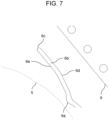
Figs. 6 to 8 .Fig. 6 is a longitudinal sectional view of air conditioner 1 according to PTL 1.Fig. 7 is a diagram illustrating a longitudinal sectional configuration nearupper end protrusion 6b of air conditioner 1.Fig. 8 is a flowchart illustrating a flow of air nearupper end protrusion 6b of air conditioner 1. - A structure of air conditioner 1 disclosed in PTL 1 will be described with reference to
Fig. 6 . Air conditioner 1 includesair blowing passage 4 that allowsair outlet 2 andsuction port 3 to communicate with each other. Air conditioner 1 includescross flow fan 5,rear guider 6, andstabilizer 7 withinair blowing passage 4,front heat exchanger 8 on a front side ofcross flow fan 5, andrear heat exchanger 9 on a rear side ofcross flow fan 5.Cross flow fan 5 includes a plurality ofblades 5a.Rear guider 6 includesproximity portion 6a that facescross flow fan 5 and is disposed to be in vicinity ofcross flow fan 5 at a predetermined distance.Cross flow fan 5 includesupper end protrusion 6b further extending fromproximity portion 6a toward an upper side ofrear heat exchanger 9. - A flow of air of air conditioner 1 disclosed in PTL 1 will be described with reference to
Fig. 7 .Upper end protrusion 6b includesupper end 6c ofupper end protrusion 6b,surface 6d ofupper end protrusion 6b facingrear heat exchanger 9, andsurface 6e ofupper end protrusion 6b facingcross flow fan 5. A suction airflow having passed through a portion ofrear heat exchanger 9 positioned belowupper end 6c ofupper end protrusion 6b flows upward alongsurface 6d ofupper end protrusion 6b facingrear heat exchanger 9, swirls towardcross flow fan 5 near the upper end ofupper end protrusion 6b, and flows intocross flow fan 5. The suction airflow having passed through a portion ofrear heat exchanger 9 positioned above the upper end ofupper end protrusion 6b merges with the suction airflow having passed throughrear heat exchanger 9 positioned below the upper end ofupper end protrusion 6b near the upper end ofupper end protrusion 6b, and flows intocross flow fan 5. A reverse vortex rotating in a direction opposite to a rotation direction ofcross flow fan 5 is generated in a space betweencross flow fan 5 andsurface 6e ofupper end protrusion 6b facingcross flow fan 5. In air conditioner 1, the reverse vortex is attached tosurface 6e ofupper end protrusion 6b facingcross flow fan 5, and a vortex center of the reverse vortex is positioned upstream ofproximity portion 6a. Thus, interference withblades 5a can be alleviated and noise can be suppressed. - Next, the flow of air near
upper end protrusion 6b of air conditioner 1 disclosed in PTL 1 will be described with reference toFig. 8 . InFig. 8 , a solid line indicates a streamline of the airflow, and a contour indicates an eddy viscosity coefficient of the airflow.Upper end protrusion 6b has a uniform shape in a longitudinal direction parallel to an axis of rotation ofcross flow fan 5. A sectional shape of the upper end ofupper end protrusion 6b in a cross section perpendicular to the axis of rotation ofcross flow fan 5 is formed by an arc tangent to the surface ofupper end protrusion 6b facingrear heat exchanger 9 and the surface ofupper end protrusion 6b facingcross flow fan 5. The reverse vortex generated in the space betweencross flow fan 5 and the surface ofupper end protrusion 6b facingcross flow fan 5 and rotating in the direction opposite to the rotation direction ofcross flow fan 5 flows along the arc ofupper end protrusion 6b toward the surface ofupper end protrusion 6b facingrear heat exchanger 9. The suction airflow having passed throughrear heat exchanger 9 positioned below the upper end ofupper end protrusion 6b flows upward along the surface ofupper end protrusion 6b facingrear heat exchanger 9, and flows toward the surface ofupper end protrusion 6b facingcross flow fan 5 along the arc ofupper end protrusion 6b. The reverse vortex and the suction airflow collide with each other near the upper end ofupper end protrusion 6b, become a turbulent airflow, and flow intocross flow fan 5. When the airflow flows intocross flow fan 5, sinceblade 5a crosses the turbulent airflow, a friction loss may occur betweenblade 5a and the suction airflow on a surface ofblade 5a, or noise due to interference may occur. In such a case, the inventors have found that there is a problem that the air blowing performance of the air conditioner is deteriorated, specifically, a blown air volume is reduced, the input power of the fan is increased, or noise cannot be suppressed. The inventors have come to construct the subject matter of the present disclosure to solve the problem. - The present disclosure provides an air conditioner capable of improving air blowing performance by suppressing collision between a suction airflow having passed through a rear heat exchanger and a reverse vortex generated in a space between a cross flow fan and a surface of an upper end protrusion facing the cross flow fan and improving turbulence of an airflow flowing into the cross flow fan.
- Hereinafter, an exemplary embodiment will be described in detail with reference to the drawings. However, unnecessarily detailed description may be omitted. For example, detailed descriptions of already well-known matters and redundant descriptions of substantially identical configurations may be omitted. This is to avoid an unnecessary redundancy in the following description and to facilitate understanding of a person skilled in the art.
- Note that, the accompanying drawings and the following descriptions are only provided to facilitate a person skilled in the art to fully understand the present disclosure, and are not intended to limit the subject matter as defined in the claims in any way.
- Hereinafter,
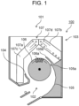
air conditioner 100 of a first exemplary embodiment will be described with reference toFigs. 1 to 3 .Fig. 1 is a longitudinal sectional view ofair conditioner 100 according to the first exemplary embodiment of the present disclosure.Fig. 2 is a diagram illustrating a longitudinal sectional configuration nearupper end protrusion 105b ofair conditioner 100.Fig. 3 is a flowchart illustrating a flow of air nearupper end protrusion 105b ofair conditioner 100. Note that, in the present exemplary embodiment, a left side inFig. 1 is referred to as a front side, and a right side inFig. 1 is referred to as a rear side. - As illustrated in
Fig. 1 ,air conditioner 100 includesbody casing 103 havingsuction port 101 andair outlet 102,stabilizer 104,rear guider 105,cross flow fan 106, andheat exchanger 107. -
Rear guider 105 includesproximity portion 105a andupper end protrusion 105b.Proximity portion 105a is a portion that facescross flow fan 106 and is disposed to be in vicinity ofcross flow fan 106 at a predetermined distance.Upper end protrusion 105b is a portion extending upward fromproximity portion 105a.Rear guider 105 is disposed betweencross flow fan 106 andrear heat exchanger 107b to be described later. -
Cross flow fan 106 includes an axis of rotation and a plurality ofblades 106a disposed in a cylindrical shape. -
Heat exchanger 107 includesfront heat exchanger 107a andrear heat exchanger 107b.Heat exchanger 107 may include an auxiliary heat exchanger.Front heat exchanger 107a is disposed at a front side ofcross flow fan 106.Rear heat exchanger 107b is disposed at a rear side ofcross flow fan 106. In a case where the auxiliary heat exchanger is provided, the auxiliary heat exchanger is disposed, for example, on a surface ofrear heat exchanger 107b opposite to a surface facingcross flow fan 106 andrear heat exchanger 107b. In other words, the auxiliary heat exchanger is disposed on a surface ofrear heat exchanger 107b upstream of air flowing in fromsuction port 101 when the cross flow fan rotates. -
Heat exchanger 107 includes a plurality offins 107c and a plurality ofheat transfer tubes 107d penetrating the plurality offins 107c. Outer diameter Dt of eachheat transfer tube 107d is less than or equal to 5 mm, for example, Dt = 5 mm in the present exemplary embodiment. - Next, in
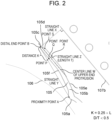
Fig. 2 , detailed shapes ofproximity portion 105a andupper end protrusion 105b ofrear guider 105 will be described. A point having a shortest distance onproximity portion 105a to crossflow fan 106 is defined as proximity point A. A straight line perpendicular to a downstream surface ofrear heat exchanger 107b is defined as straight line X.Upper end protrusion 105b hasarcuate portion 105c circumscribing straight line X, and a contact point between straight line X andarcuate portion 105c is defined as distal end point B. Distal end point B is positioned at a side ofcross flow fan 106 with respect to center line W of the upper end protrusion.Upper end protrusion 105b is configured to satisfy D/T < 0.6 when a diameter ofarcuate portion 105c is defined as D and a thickness ofupper end protrusion 105b is defined as T. - Here, in the present exemplary embodiment, center line W of the upper end protrusion and thickness T of
upper end protrusion 105b are determined as follows. A straight line connecting proximity point A and distal end point B is defined as straight line Y, and a length of straight line Y is defined as L. A point that is on straight line Y and that satisfies K = 0.25 × L when a distance from distal end point B is defined as K is defined as point P. A point that is onsurface 105f ofupper end protrusion 105b facingcross flow fan 106 and that is at a shortest distance from point P to surface 105f ofupper end protrusion 105b facingcross flow fan 106 is defined as point Q. A point that is onsurface 105e ofupper end protrusion 105b facingrear heat exchanger 107b and that is at a shortest distance from point Q tosurface 105e ofupper end protrusion 105b facingrear heat exchanger 107b is defined as point R. A straight line connecting point Q and point R is defined as straight line Z. A straight line passing through a midpoint of straight line Z and orthogonal to straight line Z is defined as center line W of the upper end protrusion. A length of line segment QR on straight line Z is defined as thickness T ofupper end protrusion 105b. -
Upper end protrusion 105b hasflat portion 105d that is tangent toarcuate portion 105c and facesrear heat exchanger 107b.Upper end protrusion 105b is configured to satisfy U/T < 1.0 when a length offlat portion 105d is defined as U. - Hereinafter, an operation of
air conditioner 100 having the above configuration will be described with reference toFig. 3 . - In
air conditioner 100,cross flow fan 106 rotates, and thus, an indoor air is sucked into body casing 103 fromsuction port 101. The indoor air sucked into body casing 103 passes throughfront heat exchanger 107a andrear heat exchanger 107b, flows intocross flow fan 106, and is blown out into an indoor space fromair outlet 102. Note that, inFigs. 1 to 3 ,cross flow fan 106 rotates clockwise. - A suction airflow having passed through a portion of
rear heat exchanger 107b positioned below an upper end ofupper end protrusion 105b due to the rotation ofcross flow fan 106 flows upward alongsurface 105e ofupper end protrusion 105b facingrear heat exchanger 107b, swirls towardcross flow fan 106 near the upper end ofupper end protrusion 105b, and flows intocross flow fan 106. The suction airflow passing through a portion ofrear heat exchanger 107b positioned above the upper end ofupper end protrusion 105b merges with the suction airflow passing through a portion ofrear heat exchanger 107b positioned below the upper end ofupper end protrusion 105b near the upper end ofupper end protrusion 105b, and flows intocross flow fan 106. In a space betweencross flow fan 106 andupper end protrusion 105b, a reverse vortex rotating in a direction opposite to a rotation direction ofcross flow fan 106 is generated. The reverse vortex adheres to surface 105f ofupper end protrusion 105b facingcross flow fan 106, and a vortex center of the reverse vortex is positioned aboveproximity portion 105a. - The suction airflow passing through the portion of
rear heat exchanger 107b positioned below the upper end ofupper end protrusion 105b flows upward alongsurface 105e ofupper end protrusion 105b facingrear heat exchanger 107b and reachesflat portion 105d. The suction airflow passing through the portion ofrear heat exchanger 107b positioned below the upper end ofupper end protrusion 105b peels off fromsurface 105e ofupper end protrusion 105b facingrear heat exchanger 107b at connection point S betweensurface 105e ofupper end protrusion 105b facingrear heat exchanger 107b andflat portion 105d by an inertial force of the suction airflow. - In the present exemplary embodiment,
surface 105e ofupper end protrusion 105b facingrear heat exchanger 107b andflat portion 105d are not continuous, and length U offlat portion 105d satisfies U/T < 1.0 with respect to thickness T ofupper end protrusion 105b. Accordingly, the suction airflow peeling off fromsurface 105e ofupper end protrusion 105b facingrear heat exchanger 107b does not adhere toflat portion 105d again and merges with the flow flowing intocross flow fan 106. - The reverse vortex flows upward along
surface 105f ofupper end protrusion 105b facingcross flow fan 106 and reachesarcuate portion 105c. In the present exemplary embodiment, inarcuate portion 105c, distal end point B is positioned at the side ofcross flow fan 106 with respect to center line W ofupper end protrusion 105b, and diameter D ofarcuate portion 105c satisfies D/T < 0.6 with respect to thickness T ofupper end protrusion 105b. As a result, the reverse vortex has a small deflection radius and is steeply deflected when the reverse vortex flows alongarcuate portion 105c. However, due to the inertial force of the reverse vortex, the reverse vortex peels off fromarcuate portion 105c and merges with the flow flowing intocross flow fan 106. Since distal end point B is positioned at the side ofcross flow fan 106 with respect to center line W ofupper end protrusion 105b, the reverse vortex peels off fromarcuate portion 105c at a position close to crossflow fan 106 and merges with the flow flowing intocross flow fan 106. - The improvement of the air blowing performance with respect to a numerical value of D/T will be described in detail with reference to
Figs. 4A to 5B .Fig. 4A is a diagram illustrating a change in blown air volume ratio ofair conditioner 100 with respect to D/T and a shape ofupper end protrusion 105b.Fig. 4B is a graph representing the change in blown air volume ratio ofair conditioner 100 with respect to the D/T.Fig. 5A is a diagram illustrating an input change (change in input power) ofcross flow fan 106 ofair conditioner 100 with respect to D/T and the shape ofupper end protrusion 105b.Fig. 5B is a graph representing the input change (change in input power) ofcross flow fan 106 ofair conditioner 100 with respect to D/T. - First, in
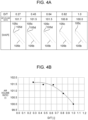
Figs. 4A and 4B , an air volume change with respect to D/T will be described.Figs. 4A and 4B illustrate air volume ratios when the number of rotations ofcross flow fan 106 ofair conditioner 100 per unit time is set to the same number of rotations by using D/T by numerical analysis as a parameter. Note that, regarding the air volume ratio inFigs. 4A and 4B , an air volume ratio when D/T = 1.0 is set to 100. InFig. 4A , the value of D/T is illustrated in an upper part, the air volume ratio is illustrated in a middle part, and the shape ofupper end protrusion 105b is illustrated in a lower part. InFig. 4B , a horizontal axis represents D/T, and a vertical axis represents an air volume ratio with respect to D/T. Assuming that D/T is decreased from 1 to 0.27, as illustrated inFig. 4B , the air volume ratio rapidly increases when D/T is between 1.0 and 0.6, and on the other hand, when D/T becomes less than 0.6, the air volume ratio maintains a substantially constant value. That is, the air volume ratio is rapidly improved when D/T is between 1.0 and 0.6, and the air volume ratio reaches an upper limit when D/T reaches 0.6. Accordingly, it can be said that, when D/T is less than 0.6, the air volume ratio is improved and the air blowing performance is improved. - In
Figs. 5A and 5B , the input change with respect to D/T will be described.Figs. 5A and 5B illustrate an input ratio when a volume of air blown out fromair conditioner 100 is set to the same blown air volume by using D/T by numerical analysis as a parameter. Note that, the input ratio inFigs. 5A and 5B is 100 when D/T = 1.0. InFig. 5A , the value of D/T is illustrated in an upper part, the input ratio is illustrated in a middle part, and the shape ofupper end protrusion 105b is illustrated in a lower part. InFig. 5B , a horizontal axis represents D/T, and a vertical axis represents the input ratio. Assuming that D/T is decreased from 1.0 to 0.27, as illustrated inFig. 5B , the input ratio is maintained at a substantially constant value when D/T is between 1.0 and 0.6, and the input ratio is rapidly decreased when D/T is less than 0.6. That is, it can be said that an effect of improving the input ratio is small when D/T is between 1.0 and 0.6 and an effect of improving the input ratio is exerted when the value of D/T is less than 0.6 with 0.6 as a boundary. That is, it can be said that, when D/T is less than 0.6, the input ratio rapidly decreases and the air blowing performance is improved. As illustrated inFig. 5B , it is found that the input ratio can be reduced by 0.5% at D/T = 0.5 as compared with D/T = 1.0. Accordingly, it can be said that, when D/T is 0.5 or less, the input ratio is further improved, and the air blowing performance is further improved. - As described above, in the present exemplary embodiment,
air conditioner 100 includesbody casing 103 havingsuction port 101 andair outlet 102,stabilizer 104,rear guider 105,cross flow fan 106,front heat exchanger 107a, andrear heat exchanger 107b.Rear guider 105 includesproximity portion 105a facingcross flow fan 106 and approachingcross flow fan 106 with a predetermined dimension (distance), andupper end protrusion 105b extending upward fromproximity portion 105a.Upper end protrusion 105b hasarcuate portion 105c, and distal end point B ofarcuate portion 105c is positioned at the side ofcross flow fan 106 with respect to center line W ofupper end protrusion 105b.Upper end protrusion 105b is configured to satisfy D/T < 0.6 when the diameter ofarcuate portion 105c is defined as D and the thickness ofupper end protrusion 105b is defined as T. - In
arcuate portion 105c, since distal end point B is positioned at the side ofcross flow fan 106 with respect to center line W ofupper end protrusion 105b and D/T < 0.6 is satisfied, the generated reverse vortex has a small deflection radius and is steeply deflected when the reverse vortex flows alongarcuate portion 105c. However, due to the inertial force of the reverse vortex, the reverse vortex peels off fromarcuate portion 105c and merges with the flow flowing intocross flow fan 106. Since distal end point B is positioned at the side ofcross flow fan 106 with respect to center line W ofupper end protrusion 105b, the reverse vortex peels off fromarcuate portion 105c at a position close to crossflow fan 106 and merges with the flow flowing intocross flow fan 106. - Accordingly, in
air conditioner 100 of the present exemplary embodiment, at the upper end ofupper end protrusion 105b, the flowing of the reverse vortex alongarcuate portion 105c ofupper end protrusion 105b towardsurface 105e ofupper end protrusion 105b facingrear heat exchanger 107b is suppressed. Accordingly, the occurrence of collision between the reverse vortex and the suction airflow can be suppressed or alleviated. Thus, the turbulence of the airflow flowing intocross flow fan 106 is improved, and thus, the blown air volume ofcross flow fan 106 can be increased. As a result, the input power to crossflow fan 106 can be reduced. The turbulence of the airflow flowing intocross flow fan 106 is improved, and thus, noise can be suppressed. - Preferably,
upper end protrusion 105b hasflat portion 105d and is configured to satisfy U/T < 1.0 when the length offlat portion 105d is defined as U. With this configuration,surface 105e ofupper end protrusion 105b facingrear heat exchanger 107b andflat portion 105d are connected not to be continuous. Accordingly, at connection point S betweensurface 105e ofupper end protrusion 105b facingrear heat exchanger 107b andflat portion 105d, the suction airflow passing throughrear heat exchanger 107b positioned below the upper end ofupper end protrusion 105b peels off fromsurface 105e ofupper end protrusion 105b facingrear heat exchanger 107b due to the inertial force of the suction airflow. Sinceflat portion 105d is configured to satisfy U/T < 1.0, the suction airflow peeling off fromsurface 105e ofupper end protrusion 105b facingrear heat exchanger 107b does not adhere toflat portion 105d again and merges with the flow flowing intocross flow fan 106. - Accordingly,
air conditioner 100 can suppress the suction airflow from flowing towardsurface 105f ofupper end protrusion 105b facingcross flow fan 106 alongarcuate portion 105c ofupper end protrusion 105b at the upper end ofupper end protrusion 105b, and can suppress or alleviate the occurrence of the collision with the reverse vortex. Thus, the turbulence of the airflow flowing intocross flow fan 106 is improved, and thus, the input power incross flow fan 106 can be reduced. As a result, the noise can be suppressed. - As in the present exemplary embodiment, outer diameter Dt of
heat transfer tube 107d may be Dt = 5 mm. However, outer diameter Dt ofheat transfer tube 107d described in the present exemplary embodiment is merely an example.Heat transfer tube 107d may satisfy Dt ≤ 5 mm. - As described above, even in a case where
air conditioner 100 includesrear heat exchanger 107b in which a pressure loss is reduced by setting outer diameter Dt ofheat transfer tube 107d to Dt = 5 mm, the turbulence of the airflow flowing intocross flow fan 106 is improved, and thus, the blown air volume incross flow fan 106 can be increased. As a result, the input power ofcross flow fan 106 can be reduced. The turbulence of the airflow flowing intocross flow fan 106 is improved, and thus, noise can be suppressed. - Note that, the exemplary embodiment described above is to exemplify the technique in the present disclosure, and thus, various modifications, replacements, additions, omissions, and the like can be made in the scope of claims or in an equivalent scope of the claims.
- The present disclosure can improve the air blowing performance by suppressing or alleviating the occurrence of the collision between the suction airflow and the reverse vortex formed upstream of the proximity portion of the rear guider and improving the turbulence of the airflow flowing into the cross flow fan. Accordingly, it can be suitably used for household air conditioning and commercial air conditioning.
-
- 100
- air conditioner
- 101
- suction port
- 102
- air outlet
- 103
- body casing
- 104
- stabilizer
- 105
- rear guider
- 105a
- proximity portion
- 105b
- upper end protrusion
- 105c
- arcuate portion
- 105d
- flat portion
- 106
- cross flow fan
- 106a
- blade
- 107
- heat exchanger
- 107a
- front heat exchanger
- 107b
- rear heat exchanger
- 107c
- fin
- 107d
- heat transfer tube
- An air conditioner comprising:
- a cross flow fan;
- a stabilizer;
- a rear guider;
- a front heat exchanger that is disposed at a front side of the cross flow fan; and
- a rear heat exchanger that is disposed at a rear side of the cross flow fan,
- wherein
- the rear guider includes
- a proximity portion that faces the cross flow fan, and is disposed to be in vicinity of the cross flow fan at a predetermined distance, and
- an upper end protrusion that extends upward from the proximity portion,
- in sectional view of the rear guider orthogonal to an axis of rotation of the cross flow fan,
- the upper end protrusion of the rear guider has an arcuate portion circumscribing a straight line X perpendicular to a downstream surface of the rear heat exchanger, and
- when a contact point at which the arcuate portion circumscribes the straight line X is a distal end point B, the distal end point B is positioned at a side of the cross flow fan with respect to a center line of the upper end protrusion, and when a diameter of the arcuate portion is defined as D and a thickness of the upper end protrusion is defined as T, D/T < 0.6 is satisfied.
- The air conditioner according to embodiment 1, wherein D/T ≤ 0.5 is satisfied.
- The air conditioner according to
embodiment 1 or 2, wherein - in the sectional view of the rear guider, the upper end protrusion has a flat portion tangent to the arcuate portion and facing the rear heat exchanger, and
- when a length of the flat portion is U, U/T < 1.0 is satisfied.
- The air conditioner according to any one of embodiment 1 to 3, wherein
- the rear heat exchanger includes a fin, and a heat transfer tube penetrating through the fin, and
- an outer diameter Dt of the heat transfer tuber satisfies Dt ≤ 5 mm.
Claims (11)
- An air conditioner (100) comprising:a cross flow fan (106);a stabilizer (104);a rear guider (105);a front heat exchanger (107a) that is disposed at a front side of the cross flow fan (106); anda rear heat exchanger (107b) that is disposed at a rear side of the cross flow fan (106),whereinthe rear guider (105) includesa proximity portion (105a) that faces the cross flow fan (106), and is disposed to be in vicinity of the cross flow fan (106) at a predetermined distance, andan upper end protrusion (105b) that extends upward from the proximity portion (105a),in sectional view of the rear guider (105) orthogonal to an axis of rotation of the cross flow fan (106),the upper end protrusion (105b) of the rear guider (105) has an arcuate portion (105c) circumscribing a straight line X perpendicular to a downstream surface of the rear heat exchanger (107b), andwhen a contact point at which the arcuate portion (105c) circumscribes the straight line X is a distal end point (B), the distal end point (B) is positioned at a side of the cross flow fan (106) with respect to a center line (W) of the upper end protrusion (105b), wherein a diameter of the arcuate portion (105c) is defined as D and a thickness of the upper end protrusion is defined as T.
- The air conditioner (100) according to claim 1, wherein D/T < 1.0 is satisfied.
- The air conditioner (100) according to claim 2, wherein D/T ≤ 0.82 is satisfied.
- The air conditioner (100) according to claim 3, wherein D/T ≤ 0.64 is satisfied.
- The air conditioner (100) according to claim 4, wherein D/T < 0.6 is satisfied.
- The air conditioner (100) according to claim 4, wherein D/T ≤ 0.5 is satisfied.
- The air conditioner (100) according to any one of claims 1 to 6, wherein in the sectional view of the rear guider (105), the upper end protrusion (105b) has a flat portion (105d).
- The air conditioner (100) according to claim 7, wherein the flat portion (105d) is tangent to the arcuate portion (105c).
- The air conditioner (100) of claims 7 or 8, wherein the flat portion (105d) faces the rear heat exchanger (107b).
- The air conditioner (100) of any of claims 7 to 9, wherein when a length of the flat portion (105d) is U, U/T < 1.0 is satisfied.
- The air conditioner (100) according to any one of claims 1 to 10, wherein the rear heat exchanger (107b) includes a fin (107c), and a heat transfer tube (107d) penetrating through the fin (107c), and an outer diameter (Dt) of the heat transfer tube (107d) satisfies Dt ≤ 5 mm.
Applications Claiming Priority (3)
| Application Number | Priority Date | Filing Date | Title |
|---|---|---|---|
| JP2022044828 | 2022-03-22 | ||
| PCT/JP2023/009491 WO2023182025A1 (en) | 2022-03-22 | 2023-03-13 | Air conditioner |
| EP23774622.7A EP4498014A4 (en) | 2022-03-22 | 2023-03-13 | Air conditioner |
Related Parent Applications (2)
| Application Number | Title | Priority Date | Filing Date |
|---|---|---|---|
| EP23774622.7A Division EP4498014A4 (en) | 2022-03-22 | 2023-03-13 | Air conditioner |
| EP23774622.7A Division-Into EP4498014A4 (en) | 2022-03-22 | 2023-03-13 | Air conditioner |
Publications (2)
| Publication Number | Publication Date |
|---|---|
| EP4530476A2 true EP4530476A2 (en) | 2025-04-02 |
| EP4530476A3 EP4530476A3 (en) | 2025-06-25 |
Family
ID=88101407
Family Applications (2)
| Application Number | Title | Priority Date | Filing Date |
|---|---|---|---|
| EP25152288.4A Pending EP4530476A3 (en) | 2022-03-22 | 2023-03-13 | Air conditioner |
| EP23774622.7A Pending EP4498014A4 (en) | 2022-03-22 | 2023-03-13 | Air conditioner |
Family Applications After (1)
| Application Number | Title | Priority Date | Filing Date |
|---|---|---|---|
| EP23774622.7A Pending EP4498014A4 (en) | 2022-03-22 | 2023-03-13 | Air conditioner |
Country Status (4)
| Country | Link |
|---|---|
| EP (2) | EP4530476A3 (en) |
| JP (1) | JPWO2023182025A1 (en) |
| CN (1) | CN118475798A (en) |
| WO (1) | WO2023182025A1 (en) |
Citations (1)
| Publication number | Priority date | Publication date | Assignee | Title |
|---|---|---|---|---|
| JP2001124362A (en) | 1999-10-27 | 2001-05-11 | Matsushita Electric Ind Co Ltd | Cross-flow blower |
Family Cites Families (6)
| Publication number | Priority date | Publication date | Assignee | Title |
|---|---|---|---|---|
| JP3326576B2 (en) * | 1994-08-25 | 2002-09-24 | 松下電器産業株式会社 | Indoor unit of air conditioner |
| JP4510172B2 (en) * | 1999-04-05 | 2010-07-21 | シャープ株式会社 | Cross flow fan |
| JP2001090689A (en) * | 1999-09-24 | 2001-04-03 | Daikin Ind Ltd | Fan mechanism and air conditioner indoor unit equipped with fan mechanism |
| JP2014020243A (en) * | 2012-07-17 | 2014-02-03 | Panasonic Corp | Cross flow air blowing device |
| JP5477441B2 (en) * | 2012-09-28 | 2014-04-23 | ダイキン工業株式会社 | Air conditioner |
| JP7620838B2 (en) * | 2019-06-17 | 2025-01-24 | パナソニックIpマネジメント株式会社 | Air conditioners |
-
2023
- 2023-03-13 EP EP25152288.4A patent/EP4530476A3/en active Pending
- 2023-03-13 JP JP2024510018A patent/JPWO2023182025A1/ja active Pending
- 2023-03-13 CN CN202380015861.4A patent/CN118475798A/en active Pending
- 2023-03-13 EP EP23774622.7A patent/EP4498014A4/en active Pending
- 2023-03-13 WO PCT/JP2023/009491 patent/WO2023182025A1/en not_active Ceased
Patent Citations (1)
| Publication number | Priority date | Publication date | Assignee | Title |
|---|---|---|---|---|
| JP2001124362A (en) | 1999-10-27 | 2001-05-11 | Matsushita Electric Ind Co Ltd | Cross-flow blower |
Also Published As
| Publication number | Publication date |
|---|---|
| JPWO2023182025A1 (en) | 2023-09-28 |
| WO2023182025A1 (en) | 2023-09-28 |
| EP4530476A3 (en) | 2025-06-25 |
| EP4498014A1 (en) | 2025-01-29 |
| CN118475798A (en) | 2024-08-09 |
| EP4498014A4 (en) | 2025-06-25 |
Similar Documents
| Publication | Publication Date | Title |
|---|---|---|
| CN103597288B (en) | Air conditioner | |
| EP2554850B1 (en) | Turbofan and indoor air conditioner equipped with same | |
| JP4998530B2 (en) | Cross-flow fan, blower and air conditioner | |
| JP2007292053A (en) | Multi-wing fan | |
| JP2011069320A5 (en) | ||
| JP6444528B2 (en) | Axial flow fan and air conditioner having the axial flow fan | |
| EP4428375A1 (en) | Fan and impeller | |
| CN111750436B (en) | Ceiling embedded air conditioner | |
| EP4530476A2 (en) | Air conditioner | |
| EP2280176B1 (en) | Cross flow fan and air conditioner equipped with same | |
| EP2472190B1 (en) | Fan unit and air conditioner equipped with fan unit | |
| JP6554665B2 (en) | Air conditioner | |
| EP3985323B1 (en) | Air conditioner | |
| EP4027018A1 (en) | Cross flow fan blade, cross flow fan, and air conditioner indoor unit | |
| EP2905474A1 (en) | Propeller fan | |
| JP2006275488A (en) | Air conditioner | |
| JP2016145661A (en) | Air conditioner | |
| US12140325B2 (en) | Air conditioner including a centrifugal fan | |
| JP4698818B2 (en) | Multi-blade blower | |
| US12258976B2 (en) | Axial fan | |
| EP4357717A1 (en) | Heat exchanger and air conditioner | |
| EP3315786A1 (en) | Turbofan and air conditioner in which same is used | |
| JP4214994B2 (en) | Air conditioner | |
| JP2023139347A (en) | air conditioner | |
| CN118148955A (en) | Centrifugal fan blade and air conditioner |
Legal Events
| Date | Code | Title | Description |
|---|---|---|---|
| PUAI | Public reference made under article 153(3) epc to a published international application that has entered the european phase |
Free format text: ORIGINAL CODE: 0009012 |
|
| STAA | Information on the status of an ep patent application or granted ep patent |
Free format text: STATUS: REQUEST FOR EXAMINATION WAS MADE |
|
| 17P | Request for examination filed |
Effective date: 20250116 |
|
| AC | Divisional application: reference to earlier application |
Ref document number: 4498014 Country of ref document: EP Kind code of ref document: P |
|
| AK | Designated contracting states |
Kind code of ref document: A2 Designated state(s): AL AT BE BG CH CY CZ DE DK EE ES FI FR GB GR HR HU IE IS IT LI LT LU LV MC ME MK MT NL NO PL PT RO RS SE SI SK SM TR |
|
| PUAL | Search report despatched |
Free format text: ORIGINAL CODE: 0009013 |
|
| AK | Designated contracting states |
Kind code of ref document: A3 Designated state(s): AL AT BE BG CH CY CZ DE DK EE ES FI FR GB GR HR HU IE IS IT LI LT LU LV MC ME MK MT NL NO PL PT RO RS SE SI SK SM TR |
|
| RIC1 | Information provided on ipc code assigned before grant |
Ipc: F04D 29/66 20060101ALI20250522BHEP Ipc: F24F 13/24 20060101ALI20250522BHEP Ipc: F24F 13/20 20060101ALI20250522BHEP Ipc: F24F 1/0007 20190101ALI20250522BHEP Ipc: F04D 29/44 20060101ALI20250522BHEP Ipc: F04D 17/04 20060101ALI20250522BHEP Ipc: F04D 25/08 20060101AFI20250522BHEP |