EP4498014A1 - Klimaanlage - Google Patents
Klimaanlage Download PDFInfo
- Publication number
- EP4498014A1 EP4498014A1 EP23774622.7A EP23774622A EP4498014A1 EP 4498014 A1 EP4498014 A1 EP 4498014A1 EP 23774622 A EP23774622 A EP 23774622A EP 4498014 A1 EP4498014 A1 EP 4498014A1
- Authority
- EP
- European Patent Office
- Prior art keywords
- flow fan
- cross flow
- end protrusion
- heat exchanger
- air conditioner
- Prior art date
- Legal status (The legal status is an assumption and is not a legal conclusion. Google has not performed a legal analysis and makes no representation as to the accuracy of the status listed.)
- Pending
Links
Images


Classifications
-
- F—MECHANICAL ENGINEERING; LIGHTING; HEATING; WEAPONS; BLASTING
- F24—HEATING; RANGES; VENTILATING
- F24F—AIR-CONDITIONING; AIR-HUMIDIFICATION; VENTILATION; USE OF AIR CURRENTS FOR SCREENING
- F24F1/00—Room units for air-conditioning, e.g. separate or self-contained units or units receiving primary air from a central station
- F24F1/0007—Indoor units, e.g. fan coil units
- F24F1/0018—Indoor units, e.g. fan coil units characterised by fans
- F24F1/0025—Cross-flow or tangential fans
-
- F—MECHANICAL ENGINEERING; LIGHTING; HEATING; WEAPONS; BLASTING
- F04—POSITIVE - DISPLACEMENT MACHINES FOR LIQUIDS; PUMPS FOR LIQUIDS OR ELASTIC FLUIDS
- F04D—NON-POSITIVE-DISPLACEMENT PUMPS
- F04D17/00—Radial-flow pumps, e.g. centrifugal pumps; Helico-centrifugal pumps
- F04D17/02—Radial-flow pumps, e.g. centrifugal pumps; Helico-centrifugal pumps having non-centrifugal stages, e.g. centripetal
- F04D17/04—Radial-flow pumps, e.g. centrifugal pumps; Helico-centrifugal pumps having non-centrifugal stages, e.g. centripetal of transverse-flow type
-
- F—MECHANICAL ENGINEERING; LIGHTING; HEATING; WEAPONS; BLASTING
- F04—POSITIVE - DISPLACEMENT MACHINES FOR LIQUIDS; PUMPS FOR LIQUIDS OR ELASTIC FLUIDS
- F04D—NON-POSITIVE-DISPLACEMENT PUMPS
- F04D29/00—Details, component parts, or accessories
- F04D29/40—Casings; Connections of working fluid
- F04D29/42—Casings; Connections of working fluid for radial or helico-centrifugal pumps
- F04D29/44—Fluid-guiding means, e.g. diffusers
- F04D29/441—Fluid-guiding means, e.g. diffusers especially adapted for elastic fluid pumps
-
- F—MECHANICAL ENGINEERING; LIGHTING; HEATING; WEAPONS; BLASTING
- F04—POSITIVE - DISPLACEMENT MACHINES FOR LIQUIDS; PUMPS FOR LIQUIDS OR ELASTIC FLUIDS
- F04D—NON-POSITIVE-DISPLACEMENT PUMPS
- F04D29/00—Details, component parts, or accessories
- F04D29/66—Combating cavitation, whirls, noise, vibration or the like; Balancing
- F04D29/661—Combating cavitation, whirls, noise, vibration or the like; Balancing especially adapted for elastic fluid pumps
- F04D29/663—Sound attenuation
-
- F—MECHANICAL ENGINEERING; LIGHTING; HEATING; WEAPONS; BLASTING
- F24—HEATING; RANGES; VENTILATING
- F24F—AIR-CONDITIONING; AIR-HUMIDIFICATION; VENTILATION; USE OF AIR CURRENTS FOR SCREENING
- F24F1/00—Room units for air-conditioning, e.g. separate or self-contained units or units receiving primary air from a central station
- F24F1/0007—Indoor units, e.g. fan coil units
- F24F1/0043—Indoor units, e.g. fan coil units characterised by mounting arrangements
- F24F1/0057—Indoor units, e.g. fan coil units characterised by mounting arrangements mounted in or on a wall
-
- F—MECHANICAL ENGINEERING; LIGHTING; HEATING; WEAPONS; BLASTING
- F24—HEATING; RANGES; VENTILATING
- F24F—AIR-CONDITIONING; AIR-HUMIDIFICATION; VENTILATION; USE OF AIR CURRENTS FOR SCREENING
- F24F13/00—Details common to, or for air-conditioning, air-humidification, ventilation or use of air currents for screening
- F24F13/20—Casings or covers
-
- F—MECHANICAL ENGINEERING; LIGHTING; HEATING; WEAPONS; BLASTING
- F24—HEATING; RANGES; VENTILATING
- F24F—AIR-CONDITIONING; AIR-HUMIDIFICATION; VENTILATION; USE OF AIR CURRENTS FOR SCREENING
- F24F13/00—Details common to, or for air-conditioning, air-humidification, ventilation or use of air currents for screening
- F24F13/24—Means for preventing or suppressing noise
-
- F—MECHANICAL ENGINEERING; LIGHTING; HEATING; WEAPONS; BLASTING
- F05—INDEXING SCHEMES RELATING TO ENGINES OR PUMPS IN VARIOUS SUBCLASSES OF CLASSES F01-F04
- F05D—INDEXING SCHEME FOR ASPECTS RELATING TO NON-POSITIVE-DISPLACEMENT MACHINES OR ENGINES, GAS-TURBINES OR JET-PROPULSION PLANTS
- F05D2250/00—Geometry
- F05D2250/50—Inlet or outlet
- F05D2250/51—Inlet
Definitions
- the present disclosure mainly relates to an air conditioner for household.
- an air conditioner includes, within a housing, a cross flow fan having a plurality of blades, a stabilizer, a rear guider, and a heat exchanger.
- the heat exchanger includes a front heat exchanger disposed on a front side of the cross flow fan and a rear heat exchanger disposed on a rear side of the cross flow fan.
- Such an air conditioner is configured to suck air from a top surface side of the housing of the air conditioner, exchange heat between the sucked air and a refrigerant flowing inside the heat exchanger, and blow out the air from a bottom surface side of the housing. Accordingly, indoor air conditioning is performed.
- the air conditioner includes an air blowing passage that allows an air outlet and a suction port to communicate with each other.
- the air conditioner includes a cross flow fan, a rear guider, a stabilizer, a front heat exchanger, and a rear heat exchanger within the air blowing passage.
- the cross flow fan includes a plurality of blades.
- the rear guider includes a proximity portion that approach to face the cross flow fan and is separated from the cross flow fan by a predetermined dimension, and an upper end protrusion that further extends from the proximity portion toward an upper side of the rear heat exchanger.
- the front heat exchanger is disposed in front of the cross flow fan, and the rear heat exchanger is disposed behind the cross flow fan.
- the present disclosure provides an air conditioner that rectifies an airflow flowing into a cross flow fan and improves air blowing performance.
- An air conditioner includes a cross flow fan, a stabilizer, a rear guider, a front heat exchanger disposed at a front side of the cross flow fan, and a rear heat exchanger disposed at a rear side of the cross flow fan.
- the rear guider includes a proximity portion facing the cross flow fan and disposed to be in vicinity of the cross flow fan at a predetermined distance, and an upper end protrusion extending upward from the proximity portion.
- the upper end protrusion of the rear guider has an arcuate portion that circumscribes straight line X perpendicular to a downstream surface of the rear heat exchanger.
- distal end point B When a contact point between straight line X and the arcuate portion is defined as distal end point B, distal end point B is positioned at a side of the cross flow fan with respect to a center line of the upper end protrusion, and when a diameter of the arcuate portion is defined as D and a thickness of the upper end protrusion is defined as T, D/T ⁇ 0.6 is satisfied.
- the air conditioner of the present disclosure can improve the air blowing performance by improving the turbulence of the airflow flowing into the cross flow fan.
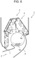
- Fig. 6 is a longitudinal sectional view of air conditioner 1 according to PTL 1.
- Fig. 7 is a diagram illustrating a longitudinal sectional configuration near upper end protrusion 6b of air conditioner 1.
- Fig. 8 is a flowchart illustrating a flow of air near upper end protrusion 6b of air conditioner 1.
- Air conditioner 1 includes air blowing passage 4 that allows air outlet 2 and suction port 3 to communicate with each other.
- Air conditioner 1 includes cross flow fan 5, rear guider 6, and stabilizer 7 within air blowing passage 4, front heat exchanger 8 on a front side of cross flow fan 5, and rear heat exchanger 9 on a rear side of cross flow fan 5.
- Cross flow fan 5 includes a plurality of blades 5a.
- Rear guider 6 includes proximity portion 6a that faces cross flow fan 5 and is disposed to be in vicinity of cross flow fan 5 at a predetermined distance.
- Cross flow fan 5 includes upper end protrusion 6b further extending from proximity portion 6a toward an upper side of rear heat exchanger 9.
- Upper end protrusion 6b includes upper end 6c of upper end protrusion 6b, surface 6d of upper end protrusion 6b facing rear heat exchanger 9, and surface 6e of upper end protrusion 6b facing cross flow fan 5.
- a suction airflow having passed through a portion of rear heat exchanger 9 positioned below upper end 6c of upper end protrusion 6b flows upward along surface 6d of upper end protrusion 6b facing rear heat exchanger 9, swirls toward cross flow fan 5 near the upper end of upper end protrusion 6b, and flows into cross flow fan 5.
- a reverse vortex rotating in a direction opposite to a rotation direction of cross flow fan 5 is generated in a space between cross flow fan 5 and surface 6e of upper end protrusion 6b facing cross flow fan 5.
- the reverse vortex is attached to surface 6e of upper end protrusion 6b facing cross flow fan 5, and a vortex center of the reverse vortex is positioned upstream of proximity portion 6a.
- a solid line indicates a streamline of the airflow
- a contour indicates an eddy viscosity coefficient of the airflow.
- Upper end protrusion 6b has a uniform shape in a longitudinal direction parallel to an axis of rotation of cross flow fan 5.
- a sectional shape of the upper end of upper end protrusion 6b in a cross section perpendicular to the axis of rotation of cross flow fan 5 is formed by an arc tangent to the surface of upper end protrusion 6b facing rear heat exchanger 9 and the surface of upper end protrusion 6b facing cross flow fan 5.
- the reverse vortex generated in the space between cross flow fan 5 and the surface of upper end protrusion 6b facing cross flow fan 5 and rotating in the direction opposite to the rotation direction of cross flow fan 5 flows along the arc of upper end protrusion 6b toward the surface of upper end protrusion 6b facing rear heat exchanger 9.
- the suction airflow having passed through rear heat exchanger 9 positioned below the upper end of upper end protrusion 6b flows upward along the surface of upper end protrusion 6b facing rear heat exchanger 9, and flows toward the surface of upper end protrusion 6b facing cross flow fan 5 along the arc of upper end protrusion 6b.
- the present disclosure provides an air conditioner capable of improving air blowing performance by suppressing collision between a suction airflow having passed through a rear heat exchanger and a reverse vortex generated in a space between a cross flow fan and a surface of an upper end protrusion facing the cross flow fan and improving turbulence of an airflow flowing into the cross flow fan.
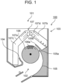
- Fig. 1 is a longitudinal sectional view of air conditioner 100 according to the first exemplary embodiment of the present disclosure.
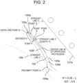
- Fig. 2 is a diagram illustrating a longitudinal sectional configuration near upper end protrusion 105b of air conditioner 100.
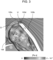
- Fig. 3 is a flowchart illustrating a flow of air near upper end protrusion 105b of air conditioner 100. Note that, in the present exemplary embodiment, a left side in Fig. 1 is referred to as a front side, and a right side in Fig. 1 is referred to as a rear side.
- air conditioner 100 includes body casing 103 having suction port 101 and air outlet 102, stabilizer 104, rear guider 105, cross flow fan 106, and heat exchanger 107.
- Rear guider 105 includes proximity portion 105a and upper end protrusion 105b.
- Proximity portion 105a is a portion that faces cross flow fan 106 and is disposed to be in vicinity of cross flow fan 106 at a predetermined distance.
- Upper end protrusion 105b is a portion extending upward from proximity portion 105a.
- Rear guider 105 is disposed between cross flow fan 106 and rear heat exchanger 107b to be described later.
- Cross flow fan 106 includes an axis of rotation and a plurality of blades 106a disposed in a cylindrical shape.
- Heat exchanger 107 includes front heat exchanger 107a and rear heat exchanger 107b. Heat exchanger 107 may include an auxiliary heat exchanger. Front heat exchanger 107a is disposed at a front side of cross flow fan 106. Rear heat exchanger 107b is disposed at a rear side of cross flow fan 106. In a case where the auxiliary heat exchanger is provided, the auxiliary heat exchanger is disposed, for example, on a surface of rear heat exchanger 107b opposite to a surface facing cross flow fan 106 and rear heat exchanger 107b. In other words, the auxiliary heat exchanger is disposed on a surface of rear heat exchanger 107b upstream of air flowing in from suction port 101 when the cross flow fan rotates.
- Heat exchanger 107 includes a plurality of fins 107c and a plurality of heat transfer tubes 107d penetrating the plurality of fins 107c.
- proximity portion 105a and upper end protrusion 105b of rear guider 105 A point having a shortest distance on proximity portion 105a to cross flow fan 106 is defined as proximity point A.
- a straight line perpendicular to a downstream surface of rear heat exchanger 107b is defined as straight line X.
- Upper end protrusion 105b has arcuate portion 105c circumscribing straight line X, and a contact point between straight line X and arcuate portion 105c is defined as distal end point B.
- Distal end point B is positioned at a side of cross flow fan 106 with respect to center line W of the upper end protrusion.
- Upper end protrusion 105b is configured to satisfy D/T ⁇ 0.6 when a diameter of arcuate portion 105c is defined as D and a thickness of upper end protrusion 105b is defined as T.
- center line W of the upper end protrusion and thickness T of upper end protrusion 105b are determined as follows.
- a straight line connecting proximity point A and distal end point B is defined as straight line Y, and a length of straight line Y is defined as L.
- a point that is on surface 105f of upper end protrusion 105b facing cross flow fan 106 and that is at a shortest distance from point P to surface 105f of upper end protrusion 105b facing cross flow fan 106 is defined as point Q.
- a point that is on surface 105e of upper end protrusion 105b facing rear heat exchanger 107b and that is at a shortest distance from point Q to surface 105e of upper end protrusion 105b facing rear heat exchanger 107b is defined as point R.
- a straight line connecting point Q and point R is defined as straight line Z.
- a straight line passing through a midpoint of straight line Z and orthogonal to straight line Z is defined as center line W of the upper end protrusion.
- a length of line segment QR on straight line Z is defined as thickness T of upper end protrusion 105b.
- Upper end protrusion 105b has flat portion 105d that is tangent to arcuate portion 105c and faces rear heat exchanger 107b. Upper end protrusion 105b is configured to satisfy U/T ⁇ 1.0 when a length of flat portion 105d is defined as U.
- cross flow fan 106 rotates, and thus, an indoor air is sucked into body casing 103 from suction port 101.
- the indoor air sucked into body casing 103 passes through front heat exchanger 107a and rear heat exchanger 107b, flows into cross flow fan 106, and is blown out into an indoor space from air outlet 102.
- cross flow fan 106 rotates clockwise.
- the suction airflow passing through a portion of rear heat exchanger 107b positioned above the upper end of upper end protrusion 105b merges with the suction airflow passing through a portion of rear heat exchanger 107b positioned below the upper end of upper end protrusion 105b near the upper end of upper end protrusion 105b, and flows into cross flow fan 106.
- a reverse vortex rotating in a direction opposite to a rotation direction of cross flow fan 106 is generated.
- the reverse vortex adheres to surface 105f of upper end protrusion 105b facing cross flow fan 106, and a vortex center of the reverse vortex is positioned above proximity portion 105a.
- the suction airflow passing through the portion of rear heat exchanger 107b positioned below the upper end of upper end protrusion 105b flows upward along surface 105e of upper end protrusion 105b facing rear heat exchanger 107b and reaches flat portion 105d.
- the suction airflow passing through the portion of rear heat exchanger 107b positioned below the upper end of upper end protrusion 105b peels off from surface 105e of upper end protrusion 105b facing rear heat exchanger 107b at connection point S between surface 105e of upper end protrusion 105b facing rear heat exchanger 107b and flat portion 105d by an inertial force of the suction airflow.
- surface 105e of upper end protrusion 105b facing rear heat exchanger 107b and flat portion 105d are not continuous, and length U of flat portion 105d satisfies U/T ⁇ 1.0 with respect to thickness T of upper end protrusion 105b. Accordingly, the suction airflow peeling off from surface 105e of upper end protrusion 105b facing rear heat exchanger 107b does not adhere to flat portion 105d again and merges with the flow flowing into cross flow fan 106.
- the reverse vortex flows upward along surface 105f of upper end protrusion 105b facing cross flow fan 106 and reaches arcuate portion 105c.
- distal end point B is positioned at the side of cross flow fan 106 with respect to center line W of upper end protrusion 105b, and diameter D of arcuate portion 105c satisfies D/T ⁇ 0.6 with respect to thickness T of upper end protrusion 105b.
- the reverse vortex has a small deflection radius and is steeply deflected when the reverse vortex flows along arcuate portion 105c.
- the reverse vortex peels off from arcuate portion 105c and merges with the flow flowing into cross flow fan 106. Since distal end point B is positioned at the side of cross flow fan 106 with respect to center line W of upper end protrusion 105b, the reverse vortex peels off from arcuate portion 105c at a position close to cross flow fan 106 and merges with the flow flowing into cross flow fan 106.
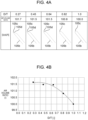
- Fig. 4A is a diagram illustrating a change in blown air volume ratio of air conditioner 100 with respect to D/T and a shape of upper end protrusion 105b.
- Fig. 4B is a graph representing the change in blown air volume ratio of air conditioner 100 with respect to the D/T.
- Fig. 5A is a diagram illustrating an input change (change in input power) of cross flow fan 106 of air conditioner 100 with respect to D/T and the shape of upper end protrusion 105b.
- Fig. 5B is a graph representing the input change (change in input power) of cross flow fan 106 of air conditioner 100 with respect to D/T.
- FIGs. 4A and 4B illustrate air volume ratios when the number of rotations of cross flow fan 106 of air conditioner 100 per unit time is set to the same number of rotations by using D/T by numerical analysis as a parameter.
- an air volume ratio when D/T 1.0 is set to 100.
- the value of D/T is illustrated in an upper part
- the air volume ratio is illustrated in a middle part
- the shape of upper end protrusion 105b is illustrated in a lower part.
- a horizontal axis represents D/T
- a vertical axis represents an air volume ratio with respect to D/T.
- the air volume ratio rapidly increases when D/T is between 1.0 and 0.6, and on the other hand, when D/T becomes less than 0.6, the air volume ratio maintains a substantially constant value. That is, the air volume ratio is rapidly improved when D/T is between 1.0 and 0.6, and the air volume ratio reaches an upper limit when D/T reaches 0.6. Accordingly, it can be said that, when D/T is less than 0.6, the air volume ratio is improved and the air blowing performance is improved.
- the value of D/T is illustrated in an upper part
- the input ratio is illustrated in a middle part
- the shape of upper end protrusion 105b is illustrated in a lower part.
- a horizontal axis represents D/T
- a vertical axis represents the input ratio.
- the input ratio is maintained at a substantially constant value when D/T is between 1.0 and 0.6, and the input ratio is rapidly decreased when D/T is less than 0.6. That is, it can be said that an effect of improving the input ratio is small when D/T is between 1.0 and 0.6 and an effect of improving the input ratio is exerted when the value of D/T is less than 0.6 with 0.6 as a boundary. That is, it can be said that, when D/T is less than 0.6, the input ratio rapidly decreases and the air blowing performance is improved. As illustrated in Fig.
- air conditioner 100 includes body casing 103 having suction port 101 and air outlet 102, stabilizer 104, rear guider 105, cross flow fan 106, front heat exchanger 107a, and rear heat exchanger 107b.
- Rear guider 105 includes proximity portion 105a facing cross flow fan 106 and approaching cross flow fan 106 with a predetermined dimension (distance), and upper end protrusion 105b extending upward from proximity portion 105a.
- Upper end protrusion 105b has arcuate portion 105c, and distal end point B of arcuate portion 105c is positioned at the side of cross flow fan 106 with respect to center line W of upper end protrusion 105b.
- Upper end protrusion 105b is configured to satisfy D/T ⁇ 0.6 when the diameter of arcuate portion 105c is defined as D and the thickness of upper end protrusion 105b is defined as T.
- the generated reverse vortex has a small deflection radius and is steeply deflected when the reverse vortex flows along arcuate portion 105c.
- the reverse vortex peels off from arcuate portion 105c and merges with the flow flowing into cross flow fan 106.
- distal end point B is positioned at the side of cross flow fan 106 with respect to center line W of upper end protrusion 105b, the reverse vortex peels off from arcuate portion 105c at a position close to cross flow fan 106 and merges with the flow flowing into cross flow fan 106.
- the flowing of the reverse vortex along arcuate portion 105c of upper end protrusion 105b toward surface 105e of upper end protrusion 105b facing rear heat exchanger 107b is suppressed. Accordingly, the occurrence of collision between the reverse vortex and the suction airflow can be suppressed or alleviated.
- the turbulence of the airflow flowing into cross flow fan 106 is improved, and thus, the blown air volume of cross flow fan 106 can be increased.
- the input power to cross flow fan 106 can be reduced.
- the turbulence of the airflow flowing into cross flow fan 106 is improved, and thus, noise can be suppressed.
- upper end protrusion 105b has flat portion 105d and is configured to satisfy U/T ⁇ 1.0 when the length of flat portion 105d is defined as U.
- surface 105e of upper end protrusion 105b facing rear heat exchanger 107b and flat portion 105d are connected not to be continuous. Accordingly, at connection point S between surface 105e of upper end protrusion 105b facing rear heat exchanger 107b and flat portion 105d, the suction airflow passing through rear heat exchanger 107b positioned below the upper end of upper end protrusion 105b peels off from surface 105e of upper end protrusion 105b facing rear heat exchanger 107b due to the inertial force of the suction airflow.
- flat portion 105d is configured to satisfy U/T ⁇ 1.0, the suction airflow peeling off from surface 105e of upper end protrusion 105b facing rear heat exchanger 107b does not adhere to flat portion 105d again and merges with the flow flowing into cross flow fan 106.
- air conditioner 100 can suppress the suction airflow from flowing toward surface 105f of upper end protrusion 105b facing cross flow fan 106 along arcuate portion 105c of upper end protrusion 105b at the upper end of upper end protrusion 105b, and can suppress or alleviate the occurrence of the collision with the reverse vortex.
- the turbulence of the airflow flowing into cross flow fan 106 is improved, and thus, the input power in cross flow fan 106 can be reduced. As a result, the noise can be suppressed.
- outer diameter Dt of heat transfer tube 107d described in the present exemplary embodiment is merely an example.
- Heat transfer tube 107d may satisfy Dt ⁇ 5 mm.
- the present disclosure can improve the air blowing performance by suppressing or alleviating the occurrence of the collision between the suction airflow and the reverse vortex formed upstream of the proximity portion of the rear guider and improving the turbulence of the airflow flowing into the cross flow fan. Accordingly, it can be suitably used for household air conditioning and commercial air conditioning.
Landscapes
- Engineering & Computer Science (AREA)
- Mechanical Engineering (AREA)
- General Engineering & Computer Science (AREA)
- Chemical & Material Sciences (AREA)
- Combustion & Propulsion (AREA)
- Air-Conditioning Room Units, And Self-Contained Units In General (AREA)
- Structures Of Non-Positive Displacement Pumps (AREA)
Priority Applications (1)
| Application Number | Priority Date | Filing Date | Title |
|---|---|---|---|
| EP25152288.4A EP4530476A3 (de) | 2022-03-22 | 2023-03-13 | Klimaanlage |
Applications Claiming Priority (2)
| Application Number | Priority Date | Filing Date | Title |
|---|---|---|---|
| JP2022044828 | 2022-03-22 | ||
| PCT/JP2023/009491 WO2023182025A1 (ja) | 2022-03-22 | 2023-03-13 | 空気調和機 |
Related Child Applications (2)
| Application Number | Title | Priority Date | Filing Date |
|---|---|---|---|
| EP25152288.4A Division EP4530476A3 (de) | 2022-03-22 | 2023-03-13 | Klimaanlage |
| EP25152288.4A Division-Into EP4530476A3 (de) | 2022-03-22 | 2023-03-13 | Klimaanlage |
Publications (2)
| Publication Number | Publication Date |
|---|---|
| EP4498014A1 true EP4498014A1 (de) | 2025-01-29 |
| EP4498014A4 EP4498014A4 (de) | 2025-06-25 |
Family
ID=88101407
Family Applications (2)
| Application Number | Title | Priority Date | Filing Date |
|---|---|---|---|
| EP25152288.4A Pending EP4530476A3 (de) | 2022-03-22 | 2023-03-13 | Klimaanlage |
| EP23774622.7A Pending EP4498014A4 (de) | 2022-03-22 | 2023-03-13 | Klimaanlage |
Family Applications Before (1)
| Application Number | Title | Priority Date | Filing Date |
|---|---|---|---|
| EP25152288.4A Pending EP4530476A3 (de) | 2022-03-22 | 2023-03-13 | Klimaanlage |
Country Status (4)
| Country | Link |
|---|---|
| EP (2) | EP4530476A3 (de) |
| JP (1) | JPWO2023182025A1 (de) |
| CN (1) | CN118475798A (de) |
| WO (1) | WO2023182025A1 (de) |
Family Cites Families (7)
| Publication number | Priority date | Publication date | Assignee | Title |
|---|---|---|---|---|
| JP3326576B2 (ja) * | 1994-08-25 | 2002-09-24 | 松下電器産業株式会社 | 空気調和機の室内ユニット |
| JP4510172B2 (ja) * | 1999-04-05 | 2010-07-21 | シャープ株式会社 | クロスフローファン |
| JP2001090689A (ja) * | 1999-09-24 | 2001-04-03 | Daikin Ind Ltd | ファン機構及びファン機構を備えた空調室内機 |
| JP2001124362A (ja) | 1999-10-27 | 2001-05-11 | Matsushita Electric Ind Co Ltd | 横断流送風装置 |
| JP2014020243A (ja) * | 2012-07-17 | 2014-02-03 | Panasonic Corp | 横断流送風装置 |
| JP5477441B2 (ja) * | 2012-09-28 | 2014-04-23 | ダイキン工業株式会社 | 空気調和機 |
| JP7620838B2 (ja) * | 2019-06-17 | 2025-01-24 | パナソニックIpマネジメント株式会社 | 空気調和機 |
-
2023
- 2023-03-13 EP EP25152288.4A patent/EP4530476A3/de active Pending
- 2023-03-13 JP JP2024510018A patent/JPWO2023182025A1/ja active Pending
- 2023-03-13 CN CN202380015861.4A patent/CN118475798A/zh active Pending
- 2023-03-13 EP EP23774622.7A patent/EP4498014A4/de active Pending
- 2023-03-13 WO PCT/JP2023/009491 patent/WO2023182025A1/ja not_active Ceased
Also Published As
| Publication number | Publication date |
|---|---|
| JPWO2023182025A1 (de) | 2023-09-28 |
| WO2023182025A1 (ja) | 2023-09-28 |
| EP4530476A3 (de) | 2025-06-25 |
| EP4530476A2 (de) | 2025-04-02 |
| CN118475798A (zh) | 2024-08-09 |
| EP4498014A4 (de) | 2025-06-25 |
Similar Documents
| Publication | Publication Date | Title |
|---|---|---|
| CN103597288B (zh) | 空气调节机 | |
| EP2554850B1 (de) | Turbolüfter und innenraum-klimaanlage damit | |
| JP4998530B2 (ja) | 貫流ファン、送風機及び空気調和機 | |
| JP2007292053A (ja) | 多翼ファン | |
| JP2011069320A5 (de) | ||
| JP6444528B2 (ja) | 軸流ファン、及び、その軸流ファンを有する空気調和装置 | |
| EP3048375A1 (de) | Klimaanlage | |
| EP4498014A1 (de) | Klimaanlage | |
| CN111750436B (zh) | 天花板埋入式空气调节机 | |
| EP2472190B1 (de) | Gebläseeinheit und damit ausgestattete klimaanlage | |
| EP2280176B1 (de) | Querstromlüfter und klimaanlage damit | |
| CN108700241B (zh) | 弯管及具备该弯管的流体机械 | |
| CN107208647A (zh) | 空气调节机 | |
| EP3985323B1 (de) | Klimaanlage | |
| EP2905474A1 (de) | Propellerlüfter | |
| JP4147560B2 (ja) | 空気調和機 | |
| EP4027018A1 (de) | Querstromlüfterschaufel, querstromlüfter und inneneinheit einer klimaanlage | |
| JP2016145661A (ja) | 空気調和機 | |
| CN115698594A (zh) | 空调装置的室外机 | |
| JP4698818B2 (ja) | 多翼送風機 | |
| US12258976B2 (en) | Axial fan | |
| EP4357717A1 (de) | Wärmetauscher und klimaanlage | |
| EP3315786A1 (de) | Turbolüfter und klimaanlage damit | |
| JP2023139347A (ja) | 空気調和機 | |
| KR100253006B1 (ko) | 터보팬 |
Legal Events
| Date | Code | Title | Description |
|---|---|---|---|
| STAA | Information on the status of an ep patent application or granted ep patent |
Free format text: STATUS: THE INTERNATIONAL PUBLICATION HAS BEEN MADE |
|
| PUAI | Public reference made under article 153(3) epc to a published international application that has entered the european phase |
Free format text: ORIGINAL CODE: 0009012 |
|
| STAA | Information on the status of an ep patent application or granted ep patent |
Free format text: STATUS: REQUEST FOR EXAMINATION WAS MADE |
|
| 17P | Request for examination filed |
Effective date: 20241022 |
|
| AK | Designated contracting states |
Kind code of ref document: A1 Designated state(s): AL AT BE BG CH CY CZ DE DK EE ES FI FR GB GR HR HU IE IS IT LI LT LU LV MC ME MK MT NL NO PL PT RO RS SE SI SK SM TR |
|
| DAV | Request for validation of the european patent (deleted) | ||
| DAX | Request for extension of the european patent (deleted) | ||
| A4 | Supplementary search report drawn up and despatched |
Effective date: 20250528 |
|
| RIC1 | Information provided on ipc code assigned before grant |
Ipc: F04D 29/44 20060101ALI20250522BHEP Ipc: F04D 25/08 20060101ALI20250522BHEP Ipc: F04D 17/04 20060101ALI20250522BHEP Ipc: F24F 1/0025 20190101ALI20250522BHEP Ipc: F24F 13/24 20060101AFI20250522BHEP |