EP4528084A1 - Appareil et procédés associés à des soupapes de dérivation de liquide de refroidissement - Google Patents
Appareil et procédés associés à des soupapes de dérivation de liquide de refroidissement Download PDFInfo
- Publication number
- EP4528084A1 EP4528084A1 EP24192907.4A EP24192907A EP4528084A1 EP 4528084 A1 EP4528084 A1 EP 4528084A1 EP 24192907 A EP24192907 A EP 24192907A EP 4528084 A1 EP4528084 A1 EP 4528084A1
- Authority
- EP
- European Patent Office
- Prior art keywords
- coolant
- diverter valve
- sensor
- coolant diverter
- cdv
- Prior art date
- Legal status (The legal status is an assumption and is not a legal conclusion. Google has not performed a legal analysis and makes no representation as to the accuracy of the status listed.)
- Pending
Links
Images


Classifications
-
- F—MECHANICAL ENGINEERING; LIGHTING; HEATING; WEAPONS; BLASTING
- F01—MACHINES OR ENGINES IN GENERAL; ENGINE PLANTS IN GENERAL; STEAM ENGINES
- F01P—COOLING OF MACHINES OR ENGINES IN GENERAL; COOLING OF INTERNAL-COMBUSTION ENGINES
- F01P11/00—Component parts, details, or accessories not provided for in, or of interest apart from, groups F01P1/00 - F01P9/00
- F01P11/14—Indicating devices; Other safety devices
- F01P11/16—Indicating devices; Other safety devices concerning coolant temperature
-
- F—MECHANICAL ENGINEERING; LIGHTING; HEATING; WEAPONS; BLASTING
- F01—MACHINES OR ENGINES IN GENERAL; ENGINE PLANTS IN GENERAL; STEAM ENGINES
- F01N—GAS-FLOW SILENCERS OR EXHAUST APPARATUS FOR MACHINES OR ENGINES IN GENERAL; GAS-FLOW SILENCERS OR EXHAUST APPARATUS FOR INTERNAL-COMBUSTION ENGINES
- F01N11/00—Monitoring or diagnostic devices for exhaust-gas treatment apparatus
-
- F—MECHANICAL ENGINEERING; LIGHTING; HEATING; WEAPONS; BLASTING
- F01—MACHINES OR ENGINES IN GENERAL; ENGINE PLANTS IN GENERAL; STEAM ENGINES
- F01N—GAS-FLOW SILENCERS OR EXHAUST APPARATUS FOR MACHINES OR ENGINES IN GENERAL; GAS-FLOW SILENCERS OR EXHAUST APPARATUS FOR INTERNAL-COMBUSTION ENGINES
- F01N3/00—Exhaust or silencing apparatus having means for purifying, rendering innocuous, or otherwise treating exhaust
- F01N3/08—Exhaust or silencing apparatus having means for purifying, rendering innocuous, or otherwise treating exhaust for rendering innocuous
- F01N3/10—Exhaust or silencing apparatus having means for purifying, rendering innocuous, or otherwise treating exhaust for rendering innocuous by thermal or catalytic conversion of noxious components of exhaust
- F01N3/18—Exhaust or silencing apparatus having means for purifying, rendering innocuous, or otherwise treating exhaust for rendering innocuous by thermal or catalytic conversion of noxious components of exhaust characterised by methods of operation; Control
- F01N3/20—Exhaust or silencing apparatus having means for purifying, rendering innocuous, or otherwise treating exhaust for rendering innocuous by thermal or catalytic conversion of noxious components of exhaust characterised by methods of operation; Control specially adapted for catalytic conversion
- F01N3/206—Adding periodically or continuously substances to exhaust gases for promoting purification, e.g. catalytic material in liquid form, NOx reducing agents
- F01N3/2066—Selective catalytic reduction [SCR]
-
- F—MECHANICAL ENGINEERING; LIGHTING; HEATING; WEAPONS; BLASTING
- F01—MACHINES OR ENGINES IN GENERAL; ENGINE PLANTS IN GENERAL; STEAM ENGINES
- F01N—GAS-FLOW SILENCERS OR EXHAUST APPARATUS FOR MACHINES OR ENGINES IN GENERAL; GAS-FLOW SILENCERS OR EXHAUST APPARATUS FOR INTERNAL-COMBUSTION ENGINES
- F01N3/00—Exhaust or silencing apparatus having means for purifying, rendering innocuous, or otherwise treating exhaust
- F01N3/08—Exhaust or silencing apparatus having means for purifying, rendering innocuous, or otherwise treating exhaust for rendering innocuous
- F01N3/10—Exhaust or silencing apparatus having means for purifying, rendering innocuous, or otherwise treating exhaust for rendering innocuous by thermal or catalytic conversion of noxious components of exhaust
- F01N3/18—Exhaust or silencing apparatus having means for purifying, rendering innocuous, or otherwise treating exhaust for rendering innocuous by thermal or catalytic conversion of noxious components of exhaust characterised by methods of operation; Control
- F01N3/20—Exhaust or silencing apparatus having means for purifying, rendering innocuous, or otherwise treating exhaust for rendering innocuous by thermal or catalytic conversion of noxious components of exhaust characterised by methods of operation; Control specially adapted for catalytic conversion
- F01N3/206—Adding periodically or continuously substances to exhaust gases for promoting purification, e.g. catalytic material in liquid form, NOx reducing agents
- F01N3/208—Control of selective catalytic reduction [SCR], e.g. by adjusting the dosing of reducing agent
-
- F—MECHANICAL ENGINEERING; LIGHTING; HEATING; WEAPONS; BLASTING
- F01—MACHINES OR ENGINES IN GENERAL; ENGINE PLANTS IN GENERAL; STEAM ENGINES
- F01P—COOLING OF MACHINES OR ENGINES IN GENERAL; COOLING OF INTERNAL-COMBUSTION ENGINES
- F01P11/00—Component parts, details, or accessories not provided for in, or of interest apart from, groups F01P1/00 - F01P9/00
- F01P11/02—Liquid-coolant filling, overflow, venting, or draining devices
- F01P11/029—Expansion reservoirs
-
- F—MECHANICAL ENGINEERING; LIGHTING; HEATING; WEAPONS; BLASTING
- F01—MACHINES OR ENGINES IN GENERAL; ENGINE PLANTS IN GENERAL; STEAM ENGINES
- F01P—COOLING OF MACHINES OR ENGINES IN GENERAL; COOLING OF INTERNAL-COMBUSTION ENGINES
- F01P11/00—Component parts, details, or accessories not provided for in, or of interest apart from, groups F01P1/00 - F01P9/00
- F01P11/14—Indicating devices; Other safety devices
- F01P11/18—Indicating devices; Other safety devices concerning coolant pressure, coolant flow, or liquid-coolant level
-
- F—MECHANICAL ENGINEERING; LIGHTING; HEATING; WEAPONS; BLASTING
- F01—MACHINES OR ENGINES IN GENERAL; ENGINE PLANTS IN GENERAL; STEAM ENGINES
- F01P—COOLING OF MACHINES OR ENGINES IN GENERAL; COOLING OF INTERNAL-COMBUSTION ENGINES
- F01P7/00—Controlling of coolant flow
- F01P7/14—Controlling of coolant flow the coolant being liquid
-
- B—PERFORMING OPERATIONS; TRANSPORTING
- B01—PHYSICAL OR CHEMICAL PROCESSES OR APPARATUS IN GENERAL
- B01D—SEPARATION
- B01D2251/00—Reactants
- B01D2251/20—Reductants
- B01D2251/206—Ammonium compounds
- B01D2251/2067—Urea
-
- B—PERFORMING OPERATIONS; TRANSPORTING
- B01—PHYSICAL OR CHEMICAL PROCESSES OR APPARATUS IN GENERAL
- B01D—SEPARATION
- B01D2258/00—Sources of waste gases
- B01D2258/01—Engine exhaust gases
- B01D2258/012—Diesel engines and lean burn gasoline engines
-
- B—PERFORMING OPERATIONS; TRANSPORTING
- B01—PHYSICAL OR CHEMICAL PROCESSES OR APPARATUS IN GENERAL
- B01D—SEPARATION
- B01D53/00—Separation of gases or vapours; Recovering vapours of volatile solvents from gases; Chemical or biological purification of waste gases, e.g. engine exhaust gases, smoke, fumes, flue gases, aerosols
- B01D53/34—Chemical or biological purification of waste gases
- B01D53/92—Chemical or biological purification of waste gases of engine exhaust gases
- B01D53/94—Chemical or biological purification of waste gases of engine exhaust gases by catalytic processes
- B01D53/9404—Removing only nitrogen compounds
- B01D53/9409—Nitrogen oxides
-
- F—MECHANICAL ENGINEERING; LIGHTING; HEATING; WEAPONS; BLASTING
- F01—MACHINES OR ENGINES IN GENERAL; ENGINE PLANTS IN GENERAL; STEAM ENGINES
- F01N—GAS-FLOW SILENCERS OR EXHAUST APPARATUS FOR MACHINES OR ENGINES IN GENERAL; GAS-FLOW SILENCERS OR EXHAUST APPARATUS FOR INTERNAL-COMBUSTION ENGINES
- F01N2610/00—Adding substances to exhaust gases
- F01N2610/02—Adding substances to exhaust gases the substance being ammonia or urea
-
- F—MECHANICAL ENGINEERING; LIGHTING; HEATING; WEAPONS; BLASTING
- F01—MACHINES OR ENGINES IN GENERAL; ENGINE PLANTS IN GENERAL; STEAM ENGINES
- F01N—GAS-FLOW SILENCERS OR EXHAUST APPARATUS FOR MACHINES OR ENGINES IN GENERAL; GAS-FLOW SILENCERS OR EXHAUST APPARATUS FOR INTERNAL-COMBUSTION ENGINES
- F01N2610/00—Adding substances to exhaust gases
- F01N2610/10—Adding substances to exhaust gases the substance being heated, e.g. by heating tank or supply line of the added substance
- F01N2610/105—Control thereof
-
- F—MECHANICAL ENGINEERING; LIGHTING; HEATING; WEAPONS; BLASTING
- F01—MACHINES OR ENGINES IN GENERAL; ENGINE PLANTS IN GENERAL; STEAM ENGINES
- F01N—GAS-FLOW SILENCERS OR EXHAUST APPARATUS FOR MACHINES OR ENGINES IN GENERAL; GAS-FLOW SILENCERS OR EXHAUST APPARATUS FOR INTERNAL-COMBUSTION ENGINES
- F01N2610/00—Adding substances to exhaust gases
- F01N2610/11—Adding substances to exhaust gases the substance or part of the dosing system being cooled
-
- F—MECHANICAL ENGINEERING; LIGHTING; HEATING; WEAPONS; BLASTING
- F01—MACHINES OR ENGINES IN GENERAL; ENGINE PLANTS IN GENERAL; STEAM ENGINES
- F01N—GAS-FLOW SILENCERS OR EXHAUST APPARATUS FOR MACHINES OR ENGINES IN GENERAL; GAS-FLOW SILENCERS OR EXHAUST APPARATUS FOR INTERNAL-COMBUSTION ENGINES
- F01N2610/00—Adding substances to exhaust gases
- F01N2610/14—Arrangements for the supply of substances, e.g. conduits
- F01N2610/1406—Storage means for substances, e.g. tanks or reservoirs
-
- F—MECHANICAL ENGINEERING; LIGHTING; HEATING; WEAPONS; BLASTING
- F01—MACHINES OR ENGINES IN GENERAL; ENGINE PLANTS IN GENERAL; STEAM ENGINES
- F01N—GAS-FLOW SILENCERS OR EXHAUST APPARATUS FOR MACHINES OR ENGINES IN GENERAL; GAS-FLOW SILENCERS OR EXHAUST APPARATUS FOR INTERNAL-COMBUSTION ENGINES
- F01N2610/00—Adding substances to exhaust gases
- F01N2610/14—Arrangements for the supply of substances, e.g. conduits
- F01N2610/1446—Means for damping of pressure fluctuations in the delivery system, e.g. by puffer volumes or throttling
-
- F—MECHANICAL ENGINEERING; LIGHTING; HEATING; WEAPONS; BLASTING
- F01—MACHINES OR ENGINES IN GENERAL; ENGINE PLANTS IN GENERAL; STEAM ENGINES
- F01N—GAS-FLOW SILENCERS OR EXHAUST APPARATUS FOR MACHINES OR ENGINES IN GENERAL; GAS-FLOW SILENCERS OR EXHAUST APPARATUS FOR INTERNAL-COMBUSTION ENGINES
- F01N2900/00—Details of electrical control or of the monitoring of the exhaust gas treating apparatus
- F01N2900/06—Parameters used for exhaust control or diagnosing
- F01N2900/18—Parameters used for exhaust control or diagnosing said parameters being related to the system for adding a substance into the exhaust
- F01N2900/1806—Properties of reducing agent or dosing system
- F01N2900/1808—Pressure
-
- F—MECHANICAL ENGINEERING; LIGHTING; HEATING; WEAPONS; BLASTING
- F01—MACHINES OR ENGINES IN GENERAL; ENGINE PLANTS IN GENERAL; STEAM ENGINES
- F01N—GAS-FLOW SILENCERS OR EXHAUST APPARATUS FOR MACHINES OR ENGINES IN GENERAL; GAS-FLOW SILENCERS OR EXHAUST APPARATUS FOR INTERNAL-COMBUSTION ENGINES
- F01N2900/00—Details of electrical control or of the monitoring of the exhaust gas treating apparatus
- F01N2900/06—Parameters used for exhaust control or diagnosing
- F01N2900/18—Parameters used for exhaust control or diagnosing said parameters being related to the system for adding a substance into the exhaust
- F01N2900/1806—Properties of reducing agent or dosing system
- F01N2900/1811—Temperature
-
- F—MECHANICAL ENGINEERING; LIGHTING; HEATING; WEAPONS; BLASTING
- F01—MACHINES OR ENGINES IN GENERAL; ENGINE PLANTS IN GENERAL; STEAM ENGINES
- F01P—COOLING OF MACHINES OR ENGINES IN GENERAL; COOLING OF INTERNAL-COMBUSTION ENGINES
- F01P7/00—Controlling of coolant flow
- F01P7/14—Controlling of coolant flow the coolant being liquid
- F01P2007/146—Controlling of coolant flow the coolant being liquid using valves
-
- F—MECHANICAL ENGINEERING; LIGHTING; HEATING; WEAPONS; BLASTING
- F01—MACHINES OR ENGINES IN GENERAL; ENGINE PLANTS IN GENERAL; STEAM ENGINES
- F01P—COOLING OF MACHINES OR ENGINES IN GENERAL; COOLING OF INTERNAL-COMBUSTION ENGINES
- F01P2025/00—Measuring
- F01P2025/04—Pressure
-
- F—MECHANICAL ENGINEERING; LIGHTING; HEATING; WEAPONS; BLASTING
- F01—MACHINES OR ENGINES IN GENERAL; ENGINE PLANTS IN GENERAL; STEAM ENGINES
- F01P—COOLING OF MACHINES OR ENGINES IN GENERAL; COOLING OF INTERNAL-COMBUSTION ENGINES
- F01P2025/00—Measuring
- F01P2025/08—Temperature
- F01P2025/13—Ambient temperature
-
- F—MECHANICAL ENGINEERING; LIGHTING; HEATING; WEAPONS; BLASTING
- F01—MACHINES OR ENGINES IN GENERAL; ENGINE PLANTS IN GENERAL; STEAM ENGINES
- F01P—COOLING OF MACHINES OR ENGINES IN GENERAL; COOLING OF INTERNAL-COMBUSTION ENGINES
- F01P2031/00—Fail safe
Definitions
- the present disclosure relates to apparatus for controlling the temperature of diesel exhaust fluid (DEF) in a DEF tank and to methods of fault detection of a coolant diverter valve (CDV).
- DEF diesel exhaust fluid
- CDV coolant diverter valve
- DEF diesel exhaust fluid
- the DEF comprises an aqueous urea solution and the exhaust system is configured to inject the DEF into the exhaust flow upstream of a Selective Catalytic Reduction (SCR) module. Subsequently, a reaction between the catalyst of the SCR and the DEF convents NOx components of the exhaust flow to nitrogen and water.
- SCR Selective Catalytic Reduction
- the DEF may be stored in a DEF tank. In cold conditions the DEF within the DEF tank may increase in viscosity, turn slushy or even freeze. To prevent this, it is known to pass heated coolant fluid through a conduit that passes through the DEF tank so as to supply heat energy to the DEF within the DEF tank. In order to prevent over-heating of the DEF in the DEF tank it is important to control the flow of the heated coolant through the DEF tank. To achieve this, it is known to provide a valve, referred to as a coolant diverter valve (CDV), to control flow of the heated coolant along the conduit. Typically, such coolant diverter valves are required to be inexpensive and simple in design.
- CDV coolant diverter valve
- valves may become blocked with debris circulating within the coolant system.
- This debris may include, for example, particles such as metal particles, rust particles, flakes detached from portions of the engine such as the radiator, casting sand, or foreign bodies entering the coolant system during filling of the coolant fluid from time to time.
- Blockage of the valve may be a particular issue where the valve is, for example, a 2 way 2 position solenoid valve because such valves comprise orifices and clearances of a small size.
- Hot DEF can decompose into ammonia or form deposits which can permeate and damage components.
- An embodiment of the present disclosure provides a method of fault detection of a coolant diverter valve, the method comprising:
- Another embodiment of the present disclosure provides an apparatus for controlling the temperature of diesel exhaust fluid in a diesel exhaust fluid tank, the apparatus comprising:
- Another embodiment of the present disclosure provides a method of fault detection of a coolant diverter valve, the method comprising:
- Another embodiment of the present disclosure provides an apparatus for controlling the temperature of diesel exhaust fluid in a diesel exhaust fluid tank, the apparatus comprising:
- the present disclosure relates generally to an apparatus 1 that comprises a coolant diverter valve (CDV) 4.
- the apparatus 1 may be coupled to or form part of an engine, for example a diesel internal combustion engine.
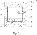
- Figure 1 illustrates schematically an example of such an apparatus 1 known in the art.
- the apparatus 1 comprises a coolant reservoir 2 comprising a coolant line outlet port 5, a diesel exhaust fluid (DEF) tank 3 for holding an aqueous urea solution 10 for injection into an exhaust system of the engine, a coolant line 20 for transferring a coolant fluid 7 discharged from the coolant reservoir 2 via the coolant line outlet port 5 to the DEF tank 3 to enable, in use, heat exchange between the coolant fluid 7 and the aqueous urea solution 10 contained in the DEF tank 3 and the CDV 4 located on the coolant line 20 for controlling flow of coolant fluid 7 along the coolant line 20 to the DEF tank 3.
- DEF diesel exhaust fluid
- the heat exchange may be achieved, for example, by passing the coolant fluid 7, which in use will have been heated by the engine, through an interior of the DEF tank 3 in for example a section of coiled conduit 22 that is supplied by the coolant line 20.
- the coiled conduit 22 may connect to a coolant return line 21 that may return the coolant fluid 7, directly or indirectly, to the coolant reservoir 7.
- CDV 4 It is known to use a solenoid valve as the CDV 4.
- An example of one such CDV 4 is shown, by way of example, in Figure 2 .
- the illustrated CDV 4 is a 2 way 2 position normally closed solenoid valve with assisted lift.
- An inlet 30 of the CDV 4 is connected to an incoming section 20A of the coolant line 20.
- An outlet 31 of the CDV 4 is connected to an outgoing section 20B of the coolant line 20.
- An armature 35 is located within a solenoid coil 36 and biased downwards away from a fixed core 40 by a spring 37.
- a seal 41 is provided at a lower end of the armature 35 for sealing an orifice 39 of the CDV 4.
- a shuttle frame 38 is captured on the lower end of the armature 35.
- the shuttle frame 38 is also engaged with a diaphragm 32 of the CDV 4.
- a diaphragm 32 of the CDV 4 When the CDV 4 is closed the diaphragm 32 sealingly engages against a main valve seat 42.
- the diaphragm 32 also defines a pilot chamber 34 above the diaphragm 32.
- a bleed hole 33 is provided in the diaphragm 32 to permit flow of fluid into the pilot chamber 34 above the diaphragm 32 from the inlet 30 when the CDV 4 is closed.
- the CDV 4 When the solenoid coil 36 is de-energised the CDV 4 is closed by engagement of the seal 41 against the orifice 39 under action of the spring 37 and the engagement of the diaphragm 32 against the main valve seat 42. At the same time the pilot chamber 34 is open to the relatively high pressure of the inlet 30 via the bleed hole 33 such that the fluid pressure in the pilot chamber 34 increases the closing force.
- Such valves may become blocked, for example from debris circulating within the apparatus 1.
- the orifice 39 may be around 1.0 mm in diameter
- the bleed hole 33 around 0.8 mm in diameter
- the radial clearance between the armature 35 and the coil 36 around 0.25 mm. Blockage of the CDV 4 may typically result in the valve remaining open, or partially open, when it should be closed.
- the apparatus 1 is modified by providing at least a first sensor 50 for measuring the pressure and/or temperature of the coolant and a controller 60.
- the first sensor 50 may be located downstream of the CDV 4. Alternatively, the first sensor 50 is located upstream of the CDV 4.
- a second sensor 51 for measuring the pressure and/or temperature of the coolant may be provided.
- the first sensor 50 may be downstream of the CDV 4 and the second sensor 51 may be upstream of the CDV 4, or vice versa.
- the first sensor 50 may be a temperature sensor, a pressure sensor or a combined temperature and pressure sensor.
- the second sensor 51 may be a temperature sensor, a pressure sensor or a combined temperature and pressure sensor.
- suitable temperature sensors include - but are not limited to - thermocouples, for example Type K thermocouples.
- suitable pressure sensors include - but are not limited to - capacitance or strain gauge based sensors, for example the 320-3062 pressure sensor from Caterpillar, Inc.
- the first sensor 50 and/or the second sensor 51 may be integrated with the CDV 4, i.e. provided within or directly coupled to a housing of the CDV 4.
- the first sensor 50 and/or the second sensor 51 may be separate from the CDV 4.
- the first sensor 50 and/or the second sensor 51 may be located proximate the CDV 4, for example on a portion of the coolant line 20 close to the CDV 4, e.g. on or close to the ingoing section 20A and/or outgoing section 20B of the coolant line 20.
- the first sensor 50 and/or the second sensor 51 may be located more remote from the CDV 4, for example at a more distant point of the coolant line 20.
- the controller 60 may be configured to determine if the CDV 4 has failed to close based on changes in the temperature and/or pressure of the coolant when the CDV 4 is commanded to close.
- Figure 3 illustrates a portion of an example apparatus 1 wherein a first sensor 50 is located downstream of the CDV 4 in the outgoing section 20B. (However, as noted above the first sensor 50 could be located at a more distal point along the coolant line).
- the first sensor 50 may be a temperature sensor.
- the coolant flowing from the coolant reservoir 2 along coolant line 20 towards the CDV 4 may have a relatively high temperature, e.g. around 80°C.
- the first sensor 50 downstream of the CDV 4 will be exposed to the coolant and the temperature reading received by the controller 60 from the first sensor 50 will be high (around 80°C).
- the CDV 4 is closed correctly the coolant will stop flowing past the first sensor 50. Consequently the temperature of the coolant proximate the first sensor 50 will start to cool towards the ambient temperature of the surroundings.
- the CDV 4 is blocked and fails to close or fully close when commanded to by the controller 60 then coolant will continue to flow past the first sensor 50.
- the temperature reading may not decrease significantly (if the CDV 4 fails substantially fully open) or may decrease at a slower than expected rate (if the CDV 4 fails partially open).
- the controller 60 may therefore be configured to determine that the CDV 4 has failed to close properly when a temperature of the coolant remains above a threshold temperature and/or when the temperature does not decay towards an ambient temperature at an expected rate when the CDV 4 is de-energised, e.g. the rate of temperature decrease is less than a threshold rate.
- Figure 4 illustrates a portion of an example apparatus 1 wherein a first sensor 50 is located downstream of the CDV 4 in the outgoing section 20B and a second sensor 51 is located upstream of the CDV 4 in the ingoing section 20A. (However, as noted above the sensors could be located at more distal points along the coolant line).
- the first sensor 50 and the second sensor 51 may both be temperature sensors.
- the first sensor 50 downstream of the CDV 4 and the second sensor 51 upstream of the CDV 4 will be exposed to the coolant and the temperature readings received by the controller 60 from both sensors will be high (around 80°C).
- the CDV 4 is closed correctly the coolant will stop flowing past the first sensor 50 and second sensor 51. Consequently the temperature of the coolant proximate the first sensor 50 and the second sensor 51 will start to cool towards the ambient temperature of the surroundings.
- the CDV 4 is blocked and fails to close or fully close when commanded to by the controller 60 then coolant will continue to flow past the first sensor 50 and the second sensor 51.
- the temperature readings may not decrease significantly (if the CDV 4 fails substantially fully open) or may decrease at a slower than expected rate (if the CDV 4 fails partially open).
- the controller 60 may therefore be configured to determine that the CDV 4 has failed to close properly when a temperature of the coolant as detected by either or both of the first sensor 50 and second sensor 51 remains above a threshold temperature and/or when the temperature detected by either or both of the first sensor 50 and second sensor 51 does not decay towards an ambient temperature at an expected rate when the CDV 4 is de-energised, e.g. the rate of temperature decrease is less than a threshold rate.
- the controller 60 may also be configured to use this as basis for determining if the CDV 4 has failed open or partially open.
- both the first sensor 50 and the second sensor 51 may increase the reliability and robustness of the determination.
- the use of both sensors may reduce the time required for the controller 60 to determine a failed open or partially open status since it may be expected that the temperature response of the first sensor 50 and the second sensor 51 will be the same or similar to one another.
- a deviation in the response of one sensor compared to the other may allow a faster determination to be achieved.
- the first sensor 50 downstream of the CDV 4 and the second sensor 51 upstream of the CDV 4 will be exposed to flowing coolant.
- the pressure at the location of the second sensor 51 upstream will typically be higher than the pressure at the location of the first sensor 50 downstream due to the pressure drop across the CDV 4.
- the controller 60 may therefore be configured to determine that the CDV 4 has failed to close properly when one or more of the following occur:
- Figure 5 illustrates a portion of an example apparatus 1 wherein a first sensor 50 is located upstream of the CDV 4 in the ingoing section 20A. (However, as noted above the first sensor 50 could be located at a more distal point along the coolant line).
- the first sensor 50 may be a temperature sensor.
- the coolant flowing from the coolant reservoir 2 along coolant line 20 towards the CDV 4 may have a relatively high temperature, e.g. around 80°C.
- the first sensor 50 upstream of the CDV 4 will be exposed to the coolant and the temperature reading received by the controller 60 from the first sensor 50 will be high (around 80°C).
- the CDV 4 is closed correctly the coolant will stop flowing past the first sensor 50. Consequently the temperature of the coolant proximate the first sensor 50 will start to cool towards the ambient temperature of the surroundings.
- the CDV 4 is blocked and fails to close or fully close when commanded to by the controller 60 then coolant will continue to flow past the first sensor 50.
- the temperature reading may not decrease significantly (if the CDV 4 fails substantially fully open) or may decrease at a slower than expected rate (if the CDV 4 fails partially open).
- the controller 60 may therefore be configured to determine that the CDV 4 has failed to close properly when a temperature of the coolant remains above a threshold temperature and/or when the temperature does not decay towards an ambient temperature at an expected rate when the CDV 4 is de-energised, e.g. the rate of temperature decrease is less than a threshold rate.
- the first sensor 50 is a pressure sensor.
- the first sensor 50 upstream of the CDV 4 When the CDV 4 is open the first sensor 50 upstream of the CDV 4 will be exposed to flowing coolant. There will typically be discernible pressure fluctuations due to the flowing of the coolant.
- the controller 60 may therefore be configured to determine that the CDV 4 has failed to close properly when one or more of the following occur:
- the apparatus 1 may further comprise a locator element 70 on the solenoid armature 35 of the CDV 4.
- the locator element 70 may be a magnetic element or a bimetallic element.
- the locater element 70 may be fixedly mounted to the surface of the solenoid armature 35, or be integrated with and/or form a part of the solenoid armature 35.
- the locator element 70 may be constrained to move in sync with the solenoid armature 35.
- the controller 60 may be configured to detect current and/or voltage fluctuations in the solenoid coil 36 of the CDV 4 caused by relative movement of the locator element 70 and the solenoid coil 36. For example, the controller 60 may determine how far downwards the locator element 70 (and hence the solenoid armature 35) has moved when closure of the CDV 4 is commanded. This may be used to determine or confirm whether the CDV 4 has fully closed.
- the first sensor 50 and/or the second sensor 51 may be omitted and the controller 60 may determine whether the CDV 4 has failed to close when the CDV 4 is de-energised based only on detecting a position of the valve element of the CDV 4 based on detecting a location of the solenoid armature 35 of the CDV using the locator element 70.
- the CDV may be for example a 2 way 2 position normally closed valve.
- the coolant may be for example water, ethylene glycol or a mixture of the same.
- the coolant reservoir may be for example an engine header coolant tank, or a whole or a part of a cylinder block or cylinder head of an engine.
- the controller 60 may be operatively connected to the CDV 4 and/or the first sensor 50 and/or the second sensor 51 by wired or wireless connections.
- the controller 60 may comprise hardware and/or software.
- the controller 60 may comprise a control unit or may be a computer program running on a dedicated or shared computing resource.
- the controller 60 may comprise a single unit or may be composed of a plurality of sub-units that are operatively connected.
- the controller 60 may be located on one processing resource or may be distributed across spatially separate computing resources.
- the controller 60 may comprise one or more programmable and or non-programmable memory units or sub-units.
- the controller 60 may comprise data storage and handling units or sub-units.
- the controller 60 may comprise or form part of an engine electronic control module (ECM) operatively connected to an engine.
- ECM engine electronic control module
- the present disclosure provides a method of fault detection of a coolant diverter valve (CDV), the method comprising:
- Determining that the CDV has failed to close properly can result in raising a fault flag and making an operator (local to or remote from the system) aware that the DEF fluid temperature is higher than intended.
- DEF fluid at higher temperatures can be corrosive and can also decompose faster to ammonia which can permeate through components and damage electrical circuits. They can also lead to deposits that can damage components. It is therefore desirable to diagnose a failed CDV valve as soon as possible.
- the first sensor may measure the pressure and/or temperature of the coolant upstream of the CDV.
- the first sensor may measure the pressure and/or temperature of the coolant downstream of the CDV.
- the first sensor may measure the temperature of the coolant and the controller may determine that the CDV has failed to close based on determining that a temperature of the coolant remains above a threshold temperature and/or does not decay towards an ambient temperature at an expected rate when the CDV is de-energised.
- the first sensor may measure the pressure of the coolant and the controller may determine that the CDV has failed to close based on whether an expected pressure change occurs when the CDV is de-energised.
- a second sensor for measuring the pressure and/or temperature of the coolant may be provided, one of the first and second sensors being upstream of the CDV and the other of the first and second sensors being downstream of the CDV.
- a controller may be provided to control operation of the CDV.
- the CDV may comprise a 2 way 2 position normally closed valve.
- a position of a valve element of the CDV may be detected, wherein the controller may determine or confirm that the CDV has failed to close when the CDV is de-energised based on a detected position of the valve element.
- the position of the valve element may be detected by detecting a location of a solenoid armature of the CDV.
- a locator element may be provided on the solenoid armature for detecting current and/or voltage fluctuations in a solenoid coil of the CDV caused by relative movement of the locator element and the solenoid coil.
- the present disclosure further provides apparatus for controlling the temperature of diesel exhaust fluid (DEF) in a DEF tank, the apparatus comprising:
- the first sensor may be located upstream of the CDV. Alternatively, the first sensor may be located downstream of the CDV.
- the first sensor may be a temperature sensor and the controller may be configured to determine that the CDV has failed to close based on determining that a temperature of the coolant remains above a threshold temperature and/or does not decay towards an ambient temperature at an expected rate when the CDV is de-energised.
- the first sensor may be a pressure sensor and the controller may be configured to determine that the CDV has failed to close based on whether an expected pressure change occurs when the CDV is de-energised.
- the apparatus may further comprise a second sensor for measuring the pressure and/or temperature of the coolant, one of the first and second sensors being upstream of the CDV and the other of the first and second sensors being downstream of the CDV.
- the coolant reservoir may be an engine header coolant tank, or a whole or a part of a cylinder block or cylinder head of an engine.
- the CDV may comprise a 2 way 2 position normally closed valve.
- the apparatus may further comprise providing a locator element on a solenoid armature of the CDV and detecting current and/or voltage fluctuations in a solenoid coil of the CDV caused by relative movement of the locator element and the solenoid coil.
- the present disclosure further provides a method of fault detection of a coolant diverter valve (CDV), the method comprising:
- the method may further comprise providing a locator element on the solenoid armature and detecting current and/or voltage fluctuations in a solenoid coil of the CDV caused by relative movement of the locator element and the solenoid coil.
- the locator element may be a magnetic element or a bimetallic element.
- the CDV may comprise a 2 way 2 position normally closed valve.
- the present disclosure further provides apparatus for controlling the temperature of diesel exhaust fluid (DEF) in a DEF tank, the apparatus comprising:
- the apparatus may further comprise providing a locator element on the solenoid armature and detecting current and/or voltage fluctuations in a solenoid coil of the CDV caused by relative movement of the locator element and the solenoid coil.
- the locator element may be a magnetic element or a bimetallic element.
- the CDV may comprise a 2 way 2 position normally closed valve.
- the apparatus finds application for engines, preferably for diesel internal combustion engines and in particular for diesel internal combustion engines that store DEF in a DEF tank.
Landscapes
- Engineering & Computer Science (AREA)
- Chemical & Material Sciences (AREA)
- Combustion & Propulsion (AREA)
- Mechanical Engineering (AREA)
- General Engineering & Computer Science (AREA)
- Chemical Kinetics & Catalysis (AREA)
- Health & Medical Sciences (AREA)
- Toxicology (AREA)
- Exhaust Gas After Treatment (AREA)
Applications Claiming Priority (1)
| Application Number | Priority Date | Filing Date | Title |
|---|---|---|---|
| GB2314596.4A GB2633824B (en) | 2023-09-22 | 2023-09-22 | Apparatus and methods related to coolant diverter valves |
Publications (1)
| Publication Number | Publication Date |
|---|---|
| EP4528084A1 true EP4528084A1 (fr) | 2025-03-26 |
Family
ID=88599226
Family Applications (1)
| Application Number | Title | Priority Date | Filing Date |
|---|---|---|---|
| EP24192907.4A Pending EP4528084A1 (fr) | 2023-09-22 | 2024-08-05 | Appareil et procédés associés à des soupapes de dérivation de liquide de refroidissement |
Country Status (4)
| Country | Link |
|---|---|
| US (1) | US12359608B2 (fr) |
| EP (1) | EP4528084A1 (fr) |
| CN (1) | CN119686850A (fr) |
| GB (1) | GB2633824B (fr) |
Citations (3)
| Publication number | Priority date | Publication date | Assignee | Title |
|---|---|---|---|---|
| US20150275732A1 (en) * | 2014-03-28 | 2015-10-01 | Caterpillar Inc. | Coolant system for reductant tank |
| US20180128140A1 (en) * | 2015-05-07 | 2018-05-10 | Volvo Construction Equipment Ab | Urea-water solution heating and cooling devices for construction equipment |
| US20210131334A1 (en) * | 2019-11-05 | 2021-05-06 | Norgren Gt Development Corporation | Coolant Control Valve |
Family Cites Families (15)
| Publication number | Priority date | Publication date | Assignee | Title |
|---|---|---|---|---|
| US6955141B2 (en) | 2003-08-06 | 2005-10-18 | General Motors Corporation | Engine cooling system |
| US20130118155A1 (en) * | 2007-10-19 | 2013-05-16 | Bosch Corporation | Control unit and control method for reductant supply device |
| JP2013217233A (ja) * | 2012-04-05 | 2013-10-24 | Isuzu Motors Ltd | 尿素水ヒーティングバルブの診断方法及びその装置 |
| JP2014001681A (ja) | 2012-06-18 | 2014-01-09 | Toyota Motor Corp | 冷却システムの異常診断装置 |
| US9540987B2 (en) | 2014-08-13 | 2017-01-10 | GM Global Technology Operations LLC | System and method for diagnosing a fault in a partitioned coolant valve |
| CN107076001B (zh) * | 2014-10-23 | 2019-08-23 | 博世株式会社 | 还原剂喷射装置的控制装置及控制方法、以及还原剂喷射装置 |
| US20150192046A1 (en) * | 2015-03-18 | 2015-07-09 | Perkins Engines Company | Injector unit for after-treatment system |
| WO2017018559A1 (fr) * | 2015-07-29 | 2017-02-02 | 볼보 컨스트럭션 이큅먼트 에이비 | Dispositif de refroidissement et de chauffage de solution d'urée destiné à un engin de chantier et son procédé de commande |
| KR101755489B1 (ko) | 2016-02-26 | 2017-07-27 | 현대자동차 주식회사 | 엔진 순환 냉각수의 제어방법 및 제어시스템 |
| KR102496812B1 (ko) | 2018-08-06 | 2023-02-06 | 현대자동차 주식회사 | 냉각 시스템의 제어 방법 |
| KR102075137B1 (ko) | 2018-09-03 | 2020-02-10 | 현대자동차(주) | 차량용 냉각시스템 제어방법 |
| IT201800009870A1 (it) * | 2018-10-29 | 2020-04-29 | Magneti Marelli Spa | Motore a combustione interna provvisto di un sistema di alimentazione di acqua ad almeno una camera di combustione |
| US10961897B2 (en) | 2019-03-01 | 2021-03-30 | Hyundai Motor Company | Methods of controlling electrical coolant valve for internal combustion engine |
| JP7447839B2 (ja) * | 2021-02-08 | 2024-03-12 | 株式会社デンソー | 尿素水供給システム |
| US11808193B2 (en) * | 2022-03-10 | 2023-11-07 | International Engine Intellectual Property Company, Llc | Preventative controls logic for coolant control valve (CCV) stuck open |
-
2023
- 2023-09-22 GB GB2314596.4A patent/GB2633824B/en active Active
-
2024
- 2024-08-05 EP EP24192907.4A patent/EP4528084A1/fr active Pending
- 2024-09-12 CN CN202411277790.8A patent/CN119686850A/zh active Pending
- 2024-09-20 US US18/891,857 patent/US12359608B2/en active Active
Patent Citations (3)
| Publication number | Priority date | Publication date | Assignee | Title |
|---|---|---|---|---|
| US20150275732A1 (en) * | 2014-03-28 | 2015-10-01 | Caterpillar Inc. | Coolant system for reductant tank |
| US20180128140A1 (en) * | 2015-05-07 | 2018-05-10 | Volvo Construction Equipment Ab | Urea-water solution heating and cooling devices for construction equipment |
| US20210131334A1 (en) * | 2019-11-05 | 2021-05-06 | Norgren Gt Development Corporation | Coolant Control Valve |
Also Published As
| Publication number | Publication date |
|---|---|
| GB2633824A (en) | 2025-03-26 |
| US12359608B2 (en) | 2025-07-15 |
| GB2633824B (en) | 2025-12-10 |
| US20250101903A1 (en) | 2025-03-27 |
| CN119686850A (zh) | 2025-03-25 |
| GB202314596D0 (en) | 2023-11-08 |
Similar Documents
| Publication | Publication Date | Title |
|---|---|---|
| EP2778361B1 (fr) | Appareil, procédé et système de diagnostic d'un dispositif de distribution d'agent réducteur | |
| CN103403317B (zh) | 车辆用冷却装置 | |
| US8763372B2 (en) | Method for heating a metering valve in an SCR system for the exhaust gas aftertreatment of an internal combustion engine | |
| US10196961B2 (en) | Cooling liquid circulation device for internal combustion engine | |
| US9982587B2 (en) | Cooling system for engine | |
| US20090250038A1 (en) | Flow sensing fuel system | |
| CN111206981A (zh) | 用于冷却散热器布置的控制阀 | |
| US20120032809A1 (en) | Method of detecting an icing state or a need for maintenance in a turbomachine fuel circuit | |
| US20150369113A1 (en) | Hydro-actuated thermostats | |
| CN101809263A (zh) | 控制调节内燃机温度的恒温器的初始打开的方法和设备 | |
| JP2001140645A (ja) | 自動車の内燃機関用冷却装置 | |
| US9394824B2 (en) | Cooling system for a combustion engine | |
| CN108292763B (zh) | 燃料电池系统的泄漏监控 | |
| EP4528084A1 (fr) | Appareil et procédés associés à des soupapes de dérivation de liquide de refroidissement | |
| JP2009228616A (ja) | 還元剤供給装置及び冷却水循環制御装置 | |
| JP4571897B2 (ja) | Egrクーラの冷却水回路 | |
| CN106574544A (zh) | 用于运行内燃机的冷却系统的方法和冷却系统中的保护系统 | |
| GB2633892A (en) | Apparatus and methods related to coolant diverter valves | |
| US20170198628A1 (en) | Method for monitoring the state of opening of a control valve of a coolant circuit of an internal combustion engine, and device for the same | |
| EP3523520B1 (fr) | Unité d'alimentation d'urée | |
| JP6082242B2 (ja) | 水温センサのバックアップシステム | |
| CN116952597A (zh) | 用于混合动力总成台架试验的冷却液控制系统及方法 | |
| US7334399B2 (en) | Apparatus, system, and method for intermittently delivering fluid | |
| CN105715354B (zh) | 发动机冷却系统及其运转方法 | |
| JPH10220639A (ja) | 開閉弁の自己診断装置 |
Legal Events
| Date | Code | Title | Description |
|---|---|---|---|
| PUAI | Public reference made under article 153(3) epc to a published international application that has entered the european phase |
Free format text: ORIGINAL CODE: 0009012 |
|
| STAA | Information on the status of an ep patent application or granted ep patent |
Free format text: STATUS: THE APPLICATION HAS BEEN PUBLISHED |
|
| AK | Designated contracting states |
Kind code of ref document: A1 Designated state(s): AL AT BE BG CH CY CZ DE DK EE ES FI FR GB GR HR HU IE IS IT LI LT LU LV MC ME MK MT NL NO PL PT RO RS SE SI SK SM TR |
|
| STAA | Information on the status of an ep patent application or granted ep patent |
Free format text: STATUS: REQUEST FOR EXAMINATION WAS MADE |
|
| STAA | Information on the status of an ep patent application or granted ep patent |
Free format text: STATUS: EXAMINATION IS IN PROGRESS |
|
| 17P | Request for examination filed |
Effective date: 20250925 |
|
| 17Q | First examination report despatched |
Effective date: 20251020 |