EP4528065A1 - Jalousievorrichtung mit unabhängiger oberseite und unterseite und schubladenartige gebäudehüllenstruktur damit - Google Patents
Jalousievorrichtung mit unabhängiger oberseite und unterseite und schubladenartige gebäudehüllenstruktur damit Download PDFInfo
- Publication number
- EP4528065A1 EP4528065A1 EP24792795.7A EP24792795A EP4528065A1 EP 4528065 A1 EP4528065 A1 EP 4528065A1 EP 24792795 A EP24792795 A EP 24792795A EP 4528065 A1 EP4528065 A1 EP 4528065A1
- Authority
- EP
- European Patent Office
- Prior art keywords
- louver
- slat
- block
- exterior
- rail
- Prior art date
- Legal status (The legal status is an assumption and is not a legal conclusion. Google has not performed a legal analysis and makes no representation as to the accuracy of the status listed.)
- Pending
Links
Images








Classifications
-
- E—FIXED CONSTRUCTIONS
- E06—DOORS, WINDOWS, SHUTTERS, OR ROLLER BLINDS IN GENERAL; LADDERS
- E06B—FIXED OR MOVABLE CLOSURES FOR OPENINGS IN BUILDINGS, VEHICLES, FENCES OR LIKE ENCLOSURES IN GENERAL, e.g. DOORS, WINDOWS, BLINDS, GATES
- E06B9/00—Screening or protective devices for wall or similar openings, with or without operating or securing mechanisms; Closures of similar construction
- E06B9/24—Screens or other constructions affording protection against light, especially against sunshine; Similar screens for privacy or appearance; Slat blinds
- E06B9/26—Lamellar or like blinds, e.g. venetian blinds
- E06B9/36—Lamellar or like blinds, e.g. venetian blinds with vertical lamellae ; Supporting rails therefor
- E06B9/367—Lamellae suspensions ; Bottom weights; Bottom guides
-
- E—FIXED CONSTRUCTIONS
- E04—BUILDING
- E04B—GENERAL BUILDING CONSTRUCTIONS; WALLS, e.g. PARTITIONS; ROOFS; FLOORS; CEILINGS; INSULATION OR OTHER PROTECTION OF BUILDINGS
- E04B2/00—Walls, e.g. partitions, for buildings; Wall construction with regard to insulation; Connections specially adapted to walls
- E04B2/88—Curtain walls
-
- E—FIXED CONSTRUCTIONS
- E04—BUILDING
- E04B—GENERAL BUILDING CONSTRUCTIONS; WALLS, e.g. PARTITIONS; ROOFS; FLOORS; CEILINGS; INSULATION OR OTHER PROTECTION OF BUILDINGS
- E04B2/00—Walls, e.g. partitions, for buildings; Wall construction with regard to insulation; Connections specially adapted to walls
- E04B2/88—Curtain walls
- E04B2/90—Curtain walls comprising panels directly attached to the structure
-
- E—FIXED CONSTRUCTIONS
- E04—BUILDING
- E04F—FINISHING WORK ON BUILDINGS, e.g. STAIRS, FLOORS
- E04F10/00—Sunshades, e.g. Florentine blinds or jalousies; Outside screens; Awnings or baldachins
- E04F10/08—Sunshades, e.g. Florentine blinds or jalousies; Outside screens; Awnings or baldachins of a plurality of similar rigid parts, e.g. slabs, lamellae
- E04F10/10—Sunshades, e.g. Florentine blinds or jalousies; Outside screens; Awnings or baldachins of a plurality of similar rigid parts, e.g. slabs, lamellae collapsible or extensible; metallic Florentine blinds; awnings with movable parts such as louvres
-
- E—FIXED CONSTRUCTIONS
- E06—DOORS, WINDOWS, SHUTTERS, OR ROLLER BLINDS IN GENERAL; LADDERS
- E06B—FIXED OR MOVABLE CLOSURES FOR OPENINGS IN BUILDINGS, VEHICLES, FENCES OR LIKE ENCLOSURES IN GENERAL, e.g. DOORS, WINDOWS, BLINDS, GATES
- E06B7/00—Special arrangements or measures in connection with doors or windows
- E06B7/02—Special arrangements or measures in connection with doors or windows for providing ventilation, e.g. through double windows; Arrangement of ventilation roses
- E06B7/08—Louvre doors, windows or grilles
- E06B7/084—Louvre doors, windows or grilles with rotatable lamellae
-
- E—FIXED CONSTRUCTIONS
- E06—DOORS, WINDOWS, SHUTTERS, OR ROLLER BLINDS IN GENERAL; LADDERS
- E06B—FIXED OR MOVABLE CLOSURES FOR OPENINGS IN BUILDINGS, VEHICLES, FENCES OR LIKE ENCLOSURES IN GENERAL, e.g. DOORS, WINDOWS, BLINDS, GATES
- E06B9/00—Screening or protective devices for wall or similar openings, with or without operating or securing mechanisms; Closures of similar construction
- E06B9/24—Screens or other constructions affording protection against light, especially against sunshine; Similar screens for privacy or appearance; Slat blinds
- E06B9/26—Lamellar or like blinds, e.g. venetian blinds
- E06B9/36—Lamellar or like blinds, e.g. venetian blinds with vertical lamellae ; Supporting rails therefor
-
- E—FIXED CONSTRUCTIONS
- E06—DOORS, WINDOWS, SHUTTERS, OR ROLLER BLINDS IN GENERAL; LADDERS
- E06B—FIXED OR MOVABLE CLOSURES FOR OPENINGS IN BUILDINGS, VEHICLES, FENCES OR LIKE ENCLOSURES IN GENERAL, e.g. DOORS, WINDOWS, BLINDS, GATES
- E06B9/00—Screening or protective devices for wall or similar openings, with or without operating or securing mechanisms; Closures of similar construction
- E06B9/24—Screens or other constructions affording protection against light, especially against sunshine; Similar screens for privacy or appearance; Slat blinds
- E06B9/26—Lamellar or like blinds, e.g. venetian blinds
- E06B9/36—Lamellar or like blinds, e.g. venetian blinds with vertical lamellae ; Supporting rails therefor
- E06B9/361—Transmissions located at the end of the supporting rail
-
- E—FIXED CONSTRUCTIONS
- E06—DOORS, WINDOWS, SHUTTERS, OR ROLLER BLINDS IN GENERAL; LADDERS
- E06B—FIXED OR MOVABLE CLOSURES FOR OPENINGS IN BUILDINGS, VEHICLES, FENCES OR LIKE ENCLOSURES IN GENERAL, e.g. DOORS, WINDOWS, BLINDS, GATES
- E06B9/00—Screening or protective devices for wall or similar openings, with or without operating or securing mechanisms; Closures of similar construction
- E06B9/24—Screens or other constructions affording protection against light, especially against sunshine; Similar screens for privacy or appearance; Slat blinds
- E06B9/26—Lamellar or like blinds, e.g. venetian blinds
- E06B9/36—Lamellar or like blinds, e.g. venetian blinds with vertical lamellae ; Supporting rails therefor
- E06B9/362—Travellers; Lamellae suspension stems
- E06B9/364—Operating mechanisms therein
-
- E—FIXED CONSTRUCTIONS
- E06—DOORS, WINDOWS, SHUTTERS, OR ROLLER BLINDS IN GENERAL; LADDERS
- E06B—FIXED OR MOVABLE CLOSURES FOR OPENINGS IN BUILDINGS, VEHICLES, FENCES OR LIKE ENCLOSURES IN GENERAL, e.g. DOORS, WINDOWS, BLINDS, GATES
- E06B9/00—Screening or protective devices for wall or similar openings, with or without operating or securing mechanisms; Closures of similar construction
- E06B9/24—Screens or other constructions affording protection against light, especially against sunshine; Similar screens for privacy or appearance; Slat blinds
- E06B9/26—Lamellar or like blinds, e.g. venetian blinds
- E06B9/36—Lamellar or like blinds, e.g. venetian blinds with vertical lamellae ; Supporting rails therefor
- E06B9/368—Driving means other than pulling cords
Definitions
- the present invention relates to a vertical louver installed on a building envelope structure and, more specifically, to a technology for a louver apparatus with independent top and bottom, which allows louvers to be opened and closed independently at the top and the bottom.
- Louvers are installed on windows or openings of a building to block external views into the interior or for purposes of lighting and ventilation.
- the louver generally includes a vertical or horizontal band-type panel installed on an upper frame of a window, and users can manually or electrically adjust the angle to control the open area, thereby seeking a comfortable indoor environment.
- Korean Patent No. 10-0863323 discloses a louver apparatus that facilitates angle adjustment of louvers in an electronic manner.
- the louver apparatus includes a rail mounted on an upper portion of a window frame, a driving unit installed on the rail to move a slider, the slider inserted inside the rail to be movable, a rotating member installed on the slider to rotate a shading louver, and a controller for controlling the driving unit.
- the louver apparatus transmits the external environmental conditions detected by an external sensor to a control unit of the controller.
- the control unit compares the detected conditions with preset condition values and controls the driving unit based on the compared result to rotate the louver at an angle set by a user.
- the direction of sunlight is changed according to seasons and time of day and varies depending on the installation location and direction of the louver.
- the louver means includes slat blocks connected to both ends of the slats and connectors connecting the slat block and the turning means, wherein the slat block includes an upper slat block that fixes the top of the slat and a lower slat block that fixes the bottom of the slat, and at least one of the upper slat block and the lower slat block includes an expansion means that allows for changes in the length between the upper and lower slat blocks.
- the slat block is in a tubular shape and has a fixed space therein.
- the expansion means includes a moving block embedded in the fixed space and moving vertically, a tension-adjusting bolt passing through one end side of the slat block and screw-coupled to one end of the moving block, and a spring installed between a head of the tension-adjusting bolt and the slat block.
- an exterior strip inclined downward outwardly is installed in front of the guide frame, an air circulation opening is formed between the exterior strip and the exterior enclosure, an airflow meter is installed inside the air circulation opening, a solarimeter is installed on the front of the exterior frame, and a surface temperature sensor is installed on the fixed frame.
- the present invention provides the following effects by independently rotating the top and bottom ends of the slats, unlike the conventional louver apparatuses.
- the present invention allows for very fine adjustments of the window area ratio, which is directly related to solar energy blocking and energy efficiency.
- the present invention can change the appearance in various shapes to provide dynamic appearances, thereby realizing a building with high symbolic value.
- the louver apparatus is installed in the exterior enclosure in the drawer-like manner, thereby facilitating replacement of the louver apparatus, allowing for efficient management by the control system, and enabling economical maintenance by coping with emergencies such as fire and strong winds.
- a louver apparatus includes: a rail means having an upper rail and a lower rail; a turning means installed in accommodating spaces of the upper and lower rails so as to be operated independently; and a louver means positioned between the upper rail and the lower rail to rotate the slats according to the operation of the turning means.
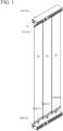
- FIG. 1 shows an overall appearance of a louver apparatus (R) according to an embodiment of the present invention
- FIG. 2 illustrates the state of the louver apparatus (R) viewed from the front.
- the rail means 10 forms the upper and lower peripheral appearance of the louver apparatus (R), which is installed on a fixing member of a building or an exterior enclosure 130, and includes a U-shaped cross-section body 11, which has an accommodating space 16 allowing the turning means 20 to be accommodated, and a detachable rail cover 15 which covers an opening of the body 11.
- R louver apparatus
- a side panel 11a of the body 11 On a side panel 11a of the body 11, fastening holes 12 and a working plate 13 for a bracket for installation of a drive motor 21 are formed. On a bottom plate 11b or an upper plate 11c, shaft holes 14 for the passage of a worm shaft 28 are formed.
- the working plate 13 is closed by a motor cover 17, and a connector 18 for the wiring for the drive motor 21 is installed on the motor cover 17.
- the rail means 10 includes an upper rail 10A located at the top of the louver means 30 and a lower rail 10B located at the bottom of the louver means 30. Additionally, turning means 20 are respectively installed in the upper rail 10A and the lower rail 10B.
- the turning means 20 allow a plurality of slats 40, which function as a screen through the louver means 30, to create various opening shapes or appearances within a range set by the rail means 10 while rotating.
- the louver means 30 includes slat blocks 33 connected to both ends of the slats 40 and connectors 32 connecting the slat blocks 33 to the turning means 20.
- the louver means 30 operates so that the slats 40 rotate according to the operation of turning means 20, thereby achieving the appearance shapes demanded by a user.
- louver apparatus (R) will be described in detail as follows.
- FIG. 3 illustrates a state in which the turning means 20 is housed in the rail means 10
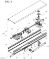
- FIG. 4 is a partially exploded view of the louver apparatus (R)
- FIG. 5 is a cross-sectional view taken along line A-A of FIG. 2 , showing the connection between turning means 20 and louver means 30, and
- FIG. 6 illustrates a state in which the ends of the slats 40 are fixed to the slat block 33.
- the turning means 20 includes a plurality of gearboxes 23, a drive motor 21, and a drive shaft 22.
- the gearboxes 23 house mechanisms that enable the slats 40 to rotate as the drive shaft 22 turns.
- a wheel gear 26, a worm gear 27 meshing with the wheel gear 26, and a worm shaft 28 are housed in each gearbox 23.
- the wheel gear 26 is fixedly mounted on the drive shaft 22 to rotate with the drive shaft 22. Additionally, the worm gear 27 is fixedly mounted on the worm shaft 28. Moreover, the worm shaft 28 is integrated with a connector 32 of the louver means 30 through a coupling 31.
- the drive motor 21 is fixedly installed on the rail means 10 via a bracket, and rotates the drive shaft 22 via a bevel gear 24.
- Shaft stoppers 25 are installed on both ends of the drive shaft 22 to prevent lateral movement of the drive shaft 22.
- the slat block 33 has a tubular shape and includes a fixed space 33a formed therein.
- a slit-shaped insertion opening 33b is formed on one side of the fixed space 33a. As illustrated in FIG. 6 , one end of the slat 40 is inserted into the insertion opening 33b, and then, is fixed to a fixing rod 34.
- the slat 40 also rotates accordingly.
- the slat block 33 of the louver means 30 includes an upper slat block 33A that fixes the top of the slat 40 and a lower slat block 33B that fixes the bottom of the slat 40. Therefore, the upper slat block 33A and the lower slat block 33B are installed on one slat 40, and the turning means 20 are respectively installed on the upper and lower slat blocks 33A and 33B.
- One end of the connector 32 of the louver means 30 is fixed to the slat block 33 and the other end is coupled and fixed to the worm shaft 28 to be integrated.
- the turning means 20 installed on the upper rail 10A and the lower rail 10B are operated independently.
- the plurality of slats 40 form various shapes of openings or appearances as described.
- the opening area of the upper portion and the opening area of the lower portion can be formed differently depending on the rotation angle of the slat block 33 or the slat 40.
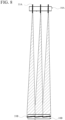
- FIGS. 7 to 9 illustrate the above, wherein FIG. 7 illustrates a cross-section along line B-B of FIG. 2 , FIG. 8 illustrates a state with only the upper portion open, and FIG. 9 illustrates a state with only the lower portion open.
- the slats 40 may be configured to have elastic force, but in another embodiment of the present invention, an expansion means allowing for length changes between the upper slat block 33A and the lower slat block 33B may be provided on any one of the upper slat block 33A and the lower slat block 33B.
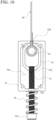
- FIG. 10 illustrates the expansion means according to an embodiment of the present invention.
- the expansion means includes a moving block 35 housed in the fixed space 33a of the slat block 33, a tension-adjusting bolt 51 connected to the moving block 35, and a spring 52 providing elastic force to the tension-adjusting bolt 51.
- the fixing rod 34 to which the end of the slat 40 is fixed is not directly embedded in the fixed space 33a but is indirectly housed inside the fixed space 33a by being located within the moving block 35.
- the moving block 35 is configured to move vertically within the fixed space 33a. Additionally, the tension-adjusting bolt 51 passes through a through-hole 33c formed on one end side of the slat block 33, and then, is screw-coupled to a spiral hole 35c formed on one end side of the moving block 35, and the spring 52 is installed between the slat block 33 and a head 51a of the tension-adjusting bolt 51.
- the restoring force by the spring 52 increases and decreases, altering the flexibility of the expansion in response to changes in the length between the upper slat block 33A and the lower slat block 33B. Therefore, when the user adjusts the tension-adjusting bolt 51 considering the material characteristics of the slat 40, the slat 40 can always maintain the taut state without any damage and the upper slat block 33A and lower slat block 33B rotate at different angles, thereby realizing the intended twisted shape stably.
- the connector 32 is installed in the center of the slat block 33, which is the central line of rotation, and the expansion means should be respectively installed on right and left sides around the slat block.
- the expansion means it is not necessary to install the expansion means to be symmetrically relative to the connector 32.
- FIG. 11 illustrates the state in which the shock-absorbing material 36 is installed on the side end of the slat block 33.
- the side ends of adjacent slats 40 should overlap completely to fully block the inside from the outside. Therefore, during the rotation of the slat blocks 33, the slat blocks 33 may collide with each other. In this instance, the shock-absorbing material 36 absorbs the the collision impact between the adjacent slat blocks 33, preventing damage or deformation of the slat blocks 33.
- the louver apparatus (R) of the present invention can applied to a drawer-type envelope structure 100 of a building, allowing for efficient management and the creation of various external appearances of the building.
- FIGS. 12 to 14 illustrate the drawer-type envelope structure 100 of the building, wherein FIG. 12 illustrates a state in which the louver apparatus (R) is installed in the exterior enclosure 130, FIG. 13 illustrates the process of forming the envelope structure 100, and FIG. 14 illustrates the process of replacing the louver apparatus (R) within the envelope structure 100.
- the guide frame 120 supports the exterior enclosure 130 from below and allows any exterior enclosure 130 to be extracted and inserted in a drawer manner from the adjacent exterior enclosure 130, and further includes guide rollers 121 installed to facilitate the extraction and insertion.
- An exterior strip 123 can be installed in front of the guide frame 120.
- the exterior strip 123 finishes a wide space between the exterior strip 123 located at the upper portion and the exterior strip 123 located at the lower portion to improve the appearance.
- An air circulation opening 123a which communicates with the interior of the exterior enclosure 130 is formed between the exterior enclosures 130.
- a flow meter 141 can be installed inside the air circulation opening 123a to enable efficient use of the louver apparatus (R).
- louver apparatus (R) of the electronic structure is embedded in the exterior enclosure 130 and members for supporting the louver apparatus are installed.
- a pyranometer 142 can be installed on the front of the exterior frame 131
- a surface temperature sensor 143 can be installed on the fixed frame 132.
- a duct 134 for installing wires to apply power to the louver apparatus (R) can be further installed inside the exterior enclosure 130.
- the exterior enclosure 130 is located outside the building envelope structure 100, and includes an exterior frame 131 where a glass panel 131a is installed, a fixed frame 132 located behind the exterior frame 131 where access windows, smoke vents, fixed insulation glass, etc., are installed, and a connection frame 133 which connects the exterior frame 131 and the fixed frame 132 while fixing the rail means 10 of the louver apparatus (R).
- the envelope structure 100 of the present invention which includes the guide frame 120 and the exterior enclosure 130, can be formed, as illustrated in FIG. 13 , through the steps of: fixing and installing the guide frame 120 to the support frame 110, lifting the exterior enclosure 130 to mount on the guide frame 120, and fixing the exterior enclosure 130 to another exterior enclosure 130 adjacent to the guide frame 120.
- the replacement of the louver apparatus (R) can be easily performed by releasing the portion where the exterior enclosure 130 which houses the louver apparatus (R) to be replaced is joined to the guide frame 120 and the adjacent exterior enclosure 130, and sliding the target exterior enclosure 130 outwards as illustrated in FIG. 14 .
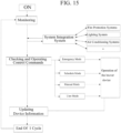
- FIG. 15 illustrates the operation sequence of a control system of the present invention.
- the louver apparatus (R) installed in the envelope structure 100 can be efficiently managed by the control system and maintain a comfortable indoor environment for occupants.
- control system sequentially performs the following steps of: a) monitoring the normal operation of the control system and the louver apparatus (R); b) exchanging information with a system integration system; c) checking and operating control commands; and d) updating device information.
- the steps proceed in a very short cycle and the cycle is continuously repeated.
- the operation sequence of the control system will be described in detail as follows.
- the initial operation of the louver apparatus (R) begins with the slats 40 aligned.
- the control system monitors the louver apparatus (R) and the control system itself to check whether the louver apparatus (R) operates correctly according to the input commands and whether the cycle of the control system is performed normally, and if everything functions properly, progress to the next step of exchanging information through transmission and reception with the system integration system.
- the system integration system displays the detected abnormality on a display device of a control room, enabling the operator to take necessary actions. b) exchanging information with system integration system;
- the system integration system manages the operational status information of various facilities within the building, such as air conditioning systems, lighting systems, and fire protection systems, and so on, and data from various sensors installed in the building, such as flow meters, lux meters, pyranometers 142, and surface temperature sensors 143, and so on to optimize the operation of each facility.
- the operational status of the louver apparatus (R) is transmitted to the system integration system, allowing the air conditioning systems or the lighting systems to consider the operational status, optimizing the operational status of each facility within the building. c) checking and operating control commands;
- a specific operation mode of the louver apparatus (R) is determined by verifying the received building and indoor environmental information and the content of the control commands input during the operation of the louver apparatus (R).
- the operation modes include an emergency mode, a schedule mode, a manual mode, and a user mode.
- the operations modes will be described as follows.
- the emergency mode involves operating the louver apparatus (R) in an appropriate state when environmental information about events such as fires or high winds is acquired.
- the operation of the louver apparatus (R) is affected by external environment conditions, such as fires or high winds, as well as situations directly related to the functions of the louver apparatus (R), such as solar radiation quantity, sun elevation, and indoor lux level.
- external environment conditions such as fires or high winds
- situations directly related to the functions of the louver apparatus (R) such as solar radiation quantity, sun elevation, and indoor lux level.
- the slats 40 it is preferable to align the slats 40 at a certain angle or move the slats 40 to one side at least in locations where smoke vents or firefighter access points are located, to communicate with the outside.
- the slats 40 may be damaged by wind pressure. So, it is necessary to align the slats 40 to minimize the impact of wind pressure on the the slats 40.
- louver apparatus (R) The operation of the louver apparatus (R) is achieved in the emergency mode.
- the schedule mode refers to a state set so that the operation of the louver apparatus (R) is based on at least one of the conditions of time, indoor lux level, sun elevation, or indoor energy use.
- the opening extent of the louver apparatus (R) is adjusted according to the indoor lux level detected in real-time by lux meters installed inside the building, and the optimal indoor lux level can be achieved in coordination with the indoor lighting system.
- the louver apparatus (R) is opened to increase the indoor lux level through daylighting, and if the indoor lux level still does not reach the set value, the indoor lighting system is activated to ensure the indoor lux level reaches the set value.
- the schedule mode based on energy use conditions functions to minimize building energy use using the louver apparatus (R). That is, the schedule mode based on energy use conditions aims to optimize energy consumption considering interior and exterior environments of the building, such as external temperature, solar radiation, occupancy density, and indoor lux level.
- a manual mode refers that the louver apparatus (R) is operated by an administrator's control due to direct intervention of the administrator to the control system.
- the event control means to operate the louver apparatus (R) to attract external attention by giving dynamic aesthetics to the appearance of the building through various shape and color changes of the slats 40.
- varying the front and back colors of the slats 40 and changes in rotation speed and direction of the upper slat block 33A and the lower slat block 33B can provide an effect similar to a card section.
- Commands for the operation of the louver apparatus (R) can be executed by the administrator in the control room or by an authorized user in a specific room.
- the present invention allows the upper and lower ends of the slats of the louver apparatus to rotate independently to finely adjust the window area ratio related to the solar energy at the upper and lower portions of the window, thereby reducing energy loss inside the building and allowing for a variety of changes to the appearance of the building. Therefore, the present invention has industrial applicability.
Landscapes
- Engineering & Computer Science (AREA)
- Structural Engineering (AREA)
- Architecture (AREA)
- Civil Engineering (AREA)
- Physics & Mathematics (AREA)
- Electromagnetism (AREA)
- Specific Sealing Or Ventilating Devices For Doors And Windows (AREA)
- Finishing Walls (AREA)
- Blinds (AREA)
Applications Claiming Priority (3)
| Application Number | Priority Date | Filing Date | Title |
|---|---|---|---|
| KR1020230050291A KR102627040B1 (ko) | 2023-04-17 | 2023-04-17 | 건물의 외피 기능을 변경하는 방법 |
| KR1020230069952A KR102627041B1 (ko) | 2023-05-31 | 2023-05-31 | 상하 독립형 루버 장치와 이를 적용한 건물의 서랍식 외피구조 |
| PCT/KR2024/001417 WO2024219607A1 (ko) | 2023-04-17 | 2024-01-30 | 상하 독립형 루버 장치와 이를 적용한 건물의 서랍식 외피구조 |
Publications (2)
| Publication Number | Publication Date |
|---|---|
| EP4528065A1 true EP4528065A1 (de) | 2025-03-26 |
| EP4528065A4 EP4528065A4 (de) | 2026-03-11 |
Family
ID=93152603
Family Applications (2)
| Application Number | Title | Priority Date | Filing Date |
|---|---|---|---|
| EP24792794.0A Pending EP4528064A1 (de) | 2023-04-17 | 2024-01-30 | Verfahren zum ändern der gebäudeumschlagfunktion |
| EP24792795.7A Pending EP4528065A4 (de) | 2023-04-17 | 2024-01-30 | Jalousievorrichtung mit unabhängiger oberseite und unterseite und schubladenartige gebäudehüllenstruktur damit |
Family Applications Before (1)
| Application Number | Title | Priority Date | Filing Date |
|---|---|---|---|
| EP24792794.0A Pending EP4528064A1 (de) | 2023-04-17 | 2024-01-30 | Verfahren zum ändern der gebäudeumschlagfunktion |
Country Status (3)
| Country | Link |
|---|---|
| US (2) | US20250314126A1 (de) |
| EP (2) | EP4528064A1 (de) |
| WO (2) | WO2024219606A1 (de) |
Family Cites Families (21)
| Publication number | Priority date | Publication date | Assignee | Title |
|---|---|---|---|---|
| US1238297A (en) * | 1917-01-25 | 1917-08-28 | Carl Severin Johanson | Extension-window guide. |
| US2524372A (en) * | 1948-03-31 | 1950-10-03 | Bopp Frederick William | Window shutter |
| US2611426A (en) * | 1950-01-30 | 1952-09-23 | Servall Products Inc | Venetian blind, including vertical tapes and means for twisting the upper and lower ends of tapes independently |
| US3134428A (en) * | 1960-01-18 | 1964-05-26 | Edgar K Orr | Louver-type window blind |
| FR2387329A1 (fr) * | 1977-04-12 | 1978-11-10 | Gen Batiment | Systeme de construction d'une facade de batiment a l'aide de panneaux de beton prefabriques |
| JPS62236988A (ja) * | 1986-04-04 | 1987-10-17 | 三機工業株式会社 | たて形ブラインド |
| FR2651519B1 (fr) * | 1989-09-04 | 1993-02-19 | Felix Andre | Panneau de revetement a cadre metallique pour la surface exterieure d'une facade. |
| JPH11336233A (ja) * | 1998-05-27 | 1999-12-07 | Ykk Architectural Products Inc | カーテンウォールユニット、ユニット式カーテンウォール、カーテンウォールユニットの取付装置および取付方法 |
| DE19911490A1 (de) * | 1999-01-29 | 2000-08-03 | Paul Schlosbauer | Verstellbare Fassadenschale mit einem Tragrahmen für ein Gebäude |
| JP3817628B2 (ja) * | 2003-03-05 | 2006-09-06 | 有限会社長友工務店 | 引き出し体の片持ち支持機構 |
| KR100652920B1 (ko) * | 2005-08-25 | 2006-12-01 | 안태인 | 갤러리 창호 |
| KR100863323B1 (ko) | 2007-07-18 | 2008-10-15 | 메코시스 주식회사 | 건물 차양용 전동 루버장치 |
| KR101377261B1 (ko) * | 2010-12-23 | 2014-03-21 | 정태락 | 2축 추미구동장치 및 이를 포함한 차양장치 |
| WO2015051545A1 (zh) * | 2013-10-12 | 2015-04-16 | 杨东佐 | 一种建筑用幕墙 |
| KR101650811B1 (ko) | 2014-09-30 | 2016-09-05 | 경희대학교 산학협력단 | 리노베이션 건물의 에너지절약 외피통풍구조 |
| JP6306079B2 (ja) * | 2016-04-14 | 2018-04-04 | 三協フロンテア株式会社 | ユニットハウス用空調機一体型パネル |
| IL265388B (en) * | 2019-03-14 | 2019-09-26 | Golan Elinor | Modular thermal panels for building shells and methods of assembling and disassembling thereof |
| KR102025822B1 (ko) * | 2019-03-29 | 2019-09-25 | 최돈우 | 커튼월 유닛 및 그의 설치구조 |
| KR102587367B1 (ko) * | 2021-03-22 | 2023-10-12 | 주식회사 인테그라디앤씨 | 스마트 융복합 건물 외피 모듈러 시스템 |
| KR102627041B1 (ko) * | 2023-05-31 | 2024-01-19 | (주)삼우종합건축사사무소 | 상하 독립형 루버 장치와 이를 적용한 건물의 서랍식 외피구조 |
| KR102627040B1 (ko) * | 2023-04-17 | 2024-01-19 | (주)삼우종합건축사사무소 | 건물의 외피 기능을 변경하는 방법 |
-
2024
- 2024-01-30 EP EP24792794.0A patent/EP4528064A1/de active Pending
- 2024-01-30 US US18/866,440 patent/US20250314126A1/en active Pending
- 2024-01-30 US US18/866,325 patent/US20250314064A1/en active Pending
- 2024-01-30 WO PCT/KR2024/001411 patent/WO2024219606A1/ko not_active Ceased
- 2024-01-30 EP EP24792795.7A patent/EP4528065A4/de active Pending
- 2024-01-30 WO PCT/KR2024/001417 patent/WO2024219607A1/ko not_active Ceased
Also Published As
| Publication number | Publication date |
|---|---|
| US20250314064A1 (en) | 2025-10-09 |
| US20250314126A1 (en) | 2025-10-09 |
| WO2024219607A1 (ko) | 2024-10-24 |
| EP4528064A1 (de) | 2025-03-26 |
| EP4528065A4 (de) | 2026-03-11 |
| WO2024219606A1 (ko) | 2024-10-24 |
Similar Documents
| Publication | Publication Date | Title |
|---|---|---|
| US8165719B2 (en) | System and method for an electrical insulating shutter system | |
| US8528621B2 (en) | Solar window shade | |
| US9708852B2 (en) | Energy-efficient integrated lighting, daylighting, and HVAC with controlled window blinds | |
| US10774579B2 (en) | Twin louver window assembly for efficient thermal control | |
| CN108884702A (zh) | 使用太阳能模块的追踪式百叶窗设备 | |
| MX2011003228A (es) | Metodo para controlar de manera automatica una cortina de ventana motorizada mientras se reducen las distracciones de los ocupantes. | |
| EP3295261B1 (de) | Energieeffiziente integrierte beleuchtung, tageslichtbeleuchtung und hlk mit elektrochromem glas | |
| CN108266851B (zh) | 一种基于窗式通风扇的室内通风系统及方法 | |
| KR102627041B1 (ko) | 상하 독립형 루버 장치와 이를 적용한 건물의 서랍식 외피구조 | |
| KR20230134788A (ko) | 각도변환수단을 갖는 루버 각도조절장치 | |
| US20250314126A1 (en) | Louver apparatus with independent top and bottom, and drawer-type building envelope structure using same | |
| Yahiaoui | Experimental study on modelling and control of lighting components in a test-cell building | |
| KR20120030183A (ko) | 자연채광 연동 차양 제어시스템 및 그 제어방법 | |
| KR20160047794A (ko) | 실내외 환경에 따라 자동으로 개폐 가능한 루버장치 | |
| EP2926055B1 (de) | Lüfter mit fensterkit | |
| CN111395931B (zh) | 一种光伏遮阳装置及其控制方法 | |
| US6478072B1 (en) | Solar screen mounting for an awning window | |
| KR101849298B1 (ko) | 풍력발전 기능을 갖는 온열 블라인드 장치 | |
| KR102041695B1 (ko) | 루버시스템의 전동오퍼레이터 | |
| JP2693366B2 (ja) | 透過光線量を任意に制御できるサンルーム | |
| KR102654262B1 (ko) | 건물 입체장식 기능을 가지는 차광시스템 | |
| GB2455813A (en) | Combined natural light and ventilation duct | |
| KR101707479B1 (ko) | 단열 창호 | |
| CN211666588U (zh) | 带有降噪通风器的固定窗 | |
| CN2203571Y (zh) | 防雨防晒室外型电动卷帘 |
Legal Events
| Date | Code | Title | Description |
|---|---|---|---|
| STAA | Information on the status of an ep patent application or granted ep patent |
Free format text: STATUS: THE INTERNATIONAL PUBLICATION HAS BEEN MADE |
|
| PUAI | Public reference made under article 153(3) epc to a published international application that has entered the european phase |
Free format text: ORIGINAL CODE: 0009012 |
|
| STAA | Information on the status of an ep patent application or granted ep patent |
Free format text: STATUS: REQUEST FOR EXAMINATION WAS MADE |
|
| 17P | Request for examination filed |
Effective date: 20241216 |
|
| AK | Designated contracting states |
Kind code of ref document: A1 Designated state(s): AL AT BE BG CH CY CZ DE DK EE ES FI FR GB GR HR HU IE IS IT LI LT LU LV MC ME MK MT NL NO PL PT RO RS SE SI SK SM TR |
|
| DAV | Request for validation of the european patent (deleted) | ||
| DAX | Request for extension of the european patent (deleted) | ||
| A4 | Supplementary search report drawn up and despatched |
Effective date: 20260211 |
|
| RIC1 | Information provided on ipc code assigned before grant |
Ipc: E06B 9/36 20060101AFI20260205BHEP Ipc: E06B 3/67 20060101ALI20260205BHEP Ipc: E06B 7/10 20060101ALI20260205BHEP Ipc: E04B 2/88 20060101ALI20260205BHEP Ipc: E06B 3/66 20060101ALI20260205BHEP Ipc: E05F 15/60 20150101ALI20260205BHEP Ipc: E05F 15/71 20150101ALI20260205BHEP Ipc: G01D 21/02 20060101ALI20260205BHEP Ipc: G06Q 50/10 20120101ALI20260205BHEP |