EP4527418A1 - Dispositif de stérilisation de fluide - Google Patents
Dispositif de stérilisation de fluide Download PDFInfo
- Publication number
- EP4527418A1 EP4527418A1 EP23826936.9A EP23826936A EP4527418A1 EP 4527418 A1 EP4527418 A1 EP 4527418A1 EP 23826936 A EP23826936 A EP 23826936A EP 4527418 A1 EP4527418 A1 EP 4527418A1
- Authority
- EP
- European Patent Office
- Prior art keywords
- tube
- fluid path
- fluid
- group
- circuit substrate
- Prior art date
- Legal status (The legal status is an assumption and is not a legal conclusion. Google has not performed a legal analysis and makes no representation as to the accuracy of the status listed.)
- Pending
Links
Images


Classifications
-
- A—HUMAN NECESSITIES
- A61—MEDICAL OR VETERINARY SCIENCE; HYGIENE
- A61L—METHODS OR APPARATUS FOR STERILISING MATERIALS OR OBJECTS IN GENERAL; DISINFECTION, STERILISATION OR DEODORISATION OF AIR; CHEMICAL ASPECTS OF BANDAGES, DRESSINGS, ABSORBENT PADS OR SURGICAL ARTICLES; MATERIALS FOR BANDAGES, DRESSINGS, ABSORBENT PADS OR SURGICAL ARTICLES
- A61L2/00—Methods or apparatus for disinfecting or sterilising materials or objects other than foodstuffs or contact lenses; Accessories therefor
- A61L2/02—Methods or apparatus for disinfecting or sterilising materials or objects other than foodstuffs or contact lenses; Accessories therefor using physical phenomena
- A61L2/08—Radiation
- A61L2/10—Ultraviolet radiation
-
- C—CHEMISTRY; METALLURGY
- C02—TREATMENT OF WATER, WASTE WATER, SEWAGE, OR SLUDGE
- C02F—TREATMENT OF WATER, WASTE WATER, SEWAGE, OR SLUDGE
- C02F1/00—Treatment of water, waste water, or sewage
- C02F1/30—Treatment of water, waste water, or sewage by irradiation
- C02F1/32—Treatment of water, waste water, or sewage by irradiation with ultraviolet light
- C02F1/325—Irradiation devices or lamp constructions
-
- A—HUMAN NECESSITIES
- A61—MEDICAL OR VETERINARY SCIENCE; HYGIENE
- A61L—METHODS OR APPARATUS FOR STERILISING MATERIALS OR OBJECTS IN GENERAL; DISINFECTION, STERILISATION OR DEODORISATION OF AIR; CHEMICAL ASPECTS OF BANDAGES, DRESSINGS, ABSORBENT PADS OR SURGICAL ARTICLES; MATERIALS FOR BANDAGES, DRESSINGS, ABSORBENT PADS OR SURGICAL ARTICLES
- A61L2202/00—Aspects relating to methods or apparatus for disinfecting or sterilising materials or objects
- A61L2202/10—Apparatus features
- A61L2202/11—Apparatus for generating biocidal substances, e.g. vaporisers, UV lamps
-
- C—CHEMISTRY; METALLURGY
- C02—TREATMENT OF WATER, WASTE WATER, SEWAGE, OR SLUDGE
- C02F—TREATMENT OF WATER, WASTE WATER, SEWAGE, OR SLUDGE
- C02F2201/00—Apparatus for treatment of water, waste water or sewage
- C02F2201/32—Details relating to UV-irradiation devices
- C02F2201/322—Lamp arrangement
- C02F2201/3222—Units using UV-light emitting diodes [LED]
-
- C—CHEMISTRY; METALLURGY
- C02—TREATMENT OF WATER, WASTE WATER, SEWAGE, OR SLUDGE
- C02F—TREATMENT OF WATER, WASTE WATER, SEWAGE, OR SLUDGE
- C02F2201/00—Apparatus for treatment of water, waste water or sewage
- C02F2201/32—Details relating to UV-irradiation devices
- C02F2201/322—Lamp arrangement
- C02F2201/3227—Units with two or more lamps
-
- C—CHEMISTRY; METALLURGY
- C02—TREATMENT OF WATER, WASTE WATER, SEWAGE, OR SLUDGE
- C02F—TREATMENT OF WATER, WASTE WATER, SEWAGE, OR SLUDGE
- C02F2303/00—Specific treatment goals
- C02F2303/04—Disinfection
Definitions
- the present invention relates to a fluid sterilization device that sterilizes a fluid flowing in a fluid path with ultraviolet light beams.
- Patent Literature 1 Japanese Patent No. 6180178
- An object of the present invention is to provide a fluid sterilization device that can achieve the miniaturization while efficiently diffusing heat generated by a light source of ultraviolet light beams to a fluid to be sterilized.
- a fluid sterilization device including a first tube and a second tube that have a first fluid path and a second fluid path that extend in a first direction in parallel to each other, and configured to be joined to each other; a circuit substrate configured to be interposed between the first tube and the second tube; a first group of light sources configured to be disposed along the first fluid path on a surface of a side of the first fluid path of the circuit substrate, and configured to irradiate the first fluid path with ultraviolet light beams; a first group of heat sinks configured to be disposed at a rear surface position of each of the light sources in the first group on a surface of a side of the second fluid path of the circuit substrate; a second group of light sources configured to be disposed at positions which do not overlap the first group of heat sinks in the first direction on the surface of the side of the second fluid path of the circuit substrate, and configured to irradiate the second fluid path with ultraviolet light beams; and a second group of heat sinks configured to be disposed
- the first fluid path and the second fluid path are separately formed on both sides of the circuit substrate, and the first group and the second group of light sources are disposed on the surfaces of the side of the first fluid path and the side the second fluid path of the circuit substrate, respectively, and irradiate the first fluid path and the second fluid path with ultraviolet light beams to perform sterilization.
- the first group and the second group of the heat sinks are respectively disposed at the rear surface positions of the light sources of the first group and the second group on the circuit substrate, and diffuse heat to the fluids of the second fluid path and the first fluid path. Accordingly, it is possible to achieve the miniaturization by devising the disposition of the light sources while having a structure in which heat generated by the light sources is effectively diffused to the fluid.
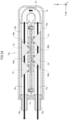
- FIG. 1 is an exploded view of a fluid sterilization device 10u according to a first embodiment, which is exploded in a longitudinal direction.
- the components interposed between a straight tube 16a and a straight tube 16b are not shown. These components will be described later with reference to FIG. 2 .
- the fluid sterilization device 10u includes a pressing plate 12, a pair of external connection tubes 14a and 14b, a pair of straight tubes 16a and 16b, a U-shaped tube 18, and a resin case 20 from one end side (+ side in the Y axis direction) to the other end side (- side in the Y axis direction) in a longitudinal direction (the Y axis direction as an example of the first direction).
- the pair of the external connection tubes 14a and 14b and the pair of the straight tubes 16a and 16b are arranged in the lateral direction (X axis direction) which is perpendicular to the longitudinal direction.
- the resin case 20 has one end open and the other end closed in the Y axis direction.
- the fluid sterilization device 10u is assembled by sequentially inserting the U-shaped tube 18, the pair of the straight tubes 16a and 16b, and the pair of the external connection tubes 14a and 14b into the resin case 20 from the opening side, and then blocking the opening of the resin case 20 by the pressing plate 12. Since the pressing plate 12 presses the flange portions of the external connection tubes 14a and 14b against the opening end portion of the resin case 20, the flange portions of the external connection tubes 14a and 14b are hidden in the resin case 20. On the other hand, the tube portions of the external connection tubes 14a and 14b penetrate the respective through-holes of the pressing plate 12 and are exposed to the outside of the resin case 20.
- FIG. 2 is an exploded view of the coupling portion of the straight tubes 16a and 16b in the lateral direction.
- the straight tubes 16a and 16b have the same structure and dimensions, and only the orientations in the lateral direction are opposite to each other in the fluid sterilization device 10u.
- the elements are indicated by reference numerals with a, b at the end of the reference numerals omitted.
- the straight tubes 16a and 16b are inserted into the resin case 20 while the rectangular planes are aligned with each other with a circuit substrate 40 interposed therebetween, with the joining side (ventral side) being a rectangular plane, and are mutually joined by the resin case 20.
- the dimension in the longitudinal direction (Y axis direction) is the same and the dimension in the width direction (Z axis direction) is the same or slightly smaller than that of the rectangular plane of the straight tube 16.
- the screw insertion hole 26 In the rectangular plane of the straight tube 16, the screw insertion hole 26, the circuit element housing hole 28, the plurality of columnar recess portions 30, and the screw insertion hole 26 are provided in order from one end side to the other end side in the Y axis direction in a row.
- a through-hole 42 is formed at the same position as each screw insertion hole 26 of the straight tube 16 in the Y axis direction.
- a female screw 54 is press-fitted into the screw insertion hole 26 of the straight tube 16a and fixed thereto prior to the fixing of the circuit substrate 40 to the straight tube 16a.
- a male screw 52 is inserted into the through-hole 42 of the circuit substrate 40 from the side of the straight tube 16b, and the shaft portion is screwed to the female screw 54. Accordingly, the circuit substrate 40 is fixed to the straight tube 16a. After the head portions of the male screws 52 are joined to the straight tubes 16a and 16b and then stored in the screw insertion holes 26 of the straight tube 16b.
- the circuit substrate 40 can also be fixed to the straight tube 16b.
- the female screw 54 is fixed in the screw insertion hole 26 of the straight tube 16b, and the male screw 52 is inserted into the through-hole 42 from the side of the straight tube 16a and then is screwed to the female screw 54 of the straight tube 16b.
- the LED 44a and the heat sink 46b are mounted at the same positions as the recess portions 30 of the straight tube 16a corresponding in the Y axis direction on the surface of the circuit substrate 40 on the side of the straight tube 16a in an alternating arrangement in the Y axis direction.
- the LED 44b and the heat sink 46a are mounted at the same positions as the recess portion 30 of the straight tube 16b corresponding in the Y axis direction on the surface of the circuit substrate 40 on the side of the straight tube 16b in an alternating arrangement in the Y axis direction.
- the heat sinks 46a and 46b are positioned at the rear surface positions of the LEDs 44a and 44b, respectively.
- Each of the ultraviolet transmission window 48 (for example, made of quartz glass) and a tubular body 50 is inserted into the recess portion 30 in a positional relationship with the bottom surface side and the opening side of the recess portion 30.
- the inner peripheral surface of the tubular body 50 is formed on a side surface of a truncated cone of which the diameter expands in a light emission direction from the LED 44.
- the tubular body 50 surrounds the LED 44 in a state of being inserted into the recess portion 30, and the ultraviolet transmission window 48 is exposed to the through-hole 31 on the bottom surface side of the recess portion 30 and blocks the recess portion 30 from the side of the through-hole 31.
- the tapered inner peripheral surface of the tubular body 50 is a mirror.
- the ultraviolet transmission window 48 has a flat plate shape, but may have a lens shape for realizing a desired light distribution.
- the circuit substrate 40 has a circuit element (not shown) such as a driving element of the LED 44, in addition to the LED 44 and the heat sink 46. These circuit elements fit into the circuit element housing hole 28 in an assembled state of the fluid sterilization device 10u.
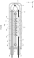
- FIG. 3 is a longitudinal cross-sectional view of the fluid sterilization device 10u taken along a direction (X axis direction) in which two straight tubes 16 are arranged.
- the orientation of the fluid sterilization device 10u of FIG. 3 is a horizontally placed orientation in which the Y axis direction is horizontal, but a typical fluid sterilization device 10u is disposed in a vertically placed orientation in which the external connection tube 14 and the U-shaped tube 18 are respectively above and below in the vertical direction.
- a white arrow indicates a direction in which the fluid to be sterilized flows in the fluid sterilization device 10u.
- the fluid is not limited to a liquid such as water, and may be a gas such as air.
- the external connection tubes 14a and 14b are connected to external devices (for example, a pump, a liquid source, and a storage tank) to be respectively inlets and outlets.
- the external connection tubes 14a and 14b can be connected to external devices to be respectively outlets and inlets.
- the straight tubes 16a and 16b have fluid paths Pa and Pb therein.
- the U-shaped tube 18 has a fluid path Pf therein.
- the fluid to be sterilized flows into the fluid sterilization device 10u from the external connection tube 14a, and then flows in the order of the fluid path Pa ⁇ the fluid path Pf ⁇ the fluid path Pb, and flows out of the fluid sterilization device 10u from the external connection tube 14b.
- the recess portion 30 is formed in a thick-walled portion of the tube wall of the straight tube 16, is open in a rectangular plane of the straight tube 16, and is a circular hole having a predetermined depth.
- the through-hole 31 extends in the radial direction of the straight tube 16 between the bottom surface of the recess portion 30 and the inner peripheral surface of the straight tube 16 to communicate the both with each other.
- the diameter and the depth of the recess portion 30 are substantially equal to the diameter and the thickness of the heat sink 46.
- the diameter of the through-hole 31 is slightly smaller than the diameter of the recess portion 30, and is a dimension that prevents the heat sink 46, the ultraviolet transmission window 48, and the tubular body 50 in the recess portion 30 from being separated from the recess portion 30 to the inner peripheral side of the straight tube 16.
- the recess portions 30 are arranged in a row in the axial direction in the straight tube 16.
- the LED 44a and the heat sink 46b are alternately stored in the recess portion 30 of the straight tube 16a in a row direction.
- the LED 44a and the heat sink 46a having a rear surface position relationship with each other are mounted on the surfaces of the circuit substrate 40 on the side of the fluid path Pa and the side of the fluid path Pb at the same position in the axial direction.
- the LED 44b and the heat sink 46b having a rear surface position relationship with each other are mounted on the surfaces of the circuit substrate 40 on the side of the fluid path Pb and the side of the fluid path Pa, respectively, at the same position in the axial direction.
- the annular tubular body 50 is fitted into the recess portion 30 in which the LED 44 is disposed, and surrounds the LED 44.
- the ultraviolet transmission window 48 is inserted into the through-hole 31 from the recess portion 30 side to block the side of the fluid path Pa or Pb of the tubular body 50.
- the O-ring 49 closely holds the peripheral portion of the ultraviolet transmission window 48 and the peripheral wall of the recess portion 30.
- the ultraviolet light beams L radiated from the LED 44 pass through the ultraviolet transmission window 48 and are applied to the fluid of the fluid path Pa or the fluid path Pb.
- D1 indicates a dimension of a total of the length of the pressing plate 12 and the length of the resin case 20 in the Y axis direction.
- D2 indicates a protruding dimension of the external connection tube 14 from the pressing plate 12 in the Y axis direction.
- D1 is, for example, 150 mm.
- D2 is, for example, 17 mm.
- ⁇ 1 and ⁇ 2 indicate diameters of the straight tube 16 and the external connection tube 14, respectively.
- ⁇ 1 is, for example, ⁇ 10 mm.
- ⁇ 2 is, for example, ⁇ 7 mm.
- FIG. 4 is a cross-sectional view taken along the line A4-A4 of FIG. 3 .
- the straight tubes 16a and 16b are inserted into the resin case 20 with the circuit substrate 40 interposed therebetween in the X axis direction, and thus, all of the straight tubes 16a and 16b and the circuit substrate 40 are held in a pinched state in the X axis direction by the inner periphery of the resin case 20. Therefore, since the circuit substrate 40 can be smoothly fixed to the straight tube 16 even without fixing the circuit substrate 40 to the straight tube 16 with the male screw 52, the male screw 52 and the female screw 54 can be omitted.
- the O-ring 47 is fitted between the peripheral wall of the recess portion 30 and the peripheral portion of the heat sink 46, and holds liquid-tightness therebetween.
- the peripheral portion of the heat sink 46 is in contact with the peripheral surface of the recess portion 30 of the straight tube 16. Therefore, the heat generated by the light emission of the LED 44 is diffused to the fluid of the fluid path Pa or the fluid path Pb by the first heat transfer path which reaches the fluid path Pa or the fluid path Pb from the bottom surface of the heat sink 46 via the fluid flowing into the through-hole 31, and is additionally conducted from the peripheral portion of the heat sink 46 to the straight tube 16, is conducted to the straight tube 16 in the circumferential direction, and, further diffused to the fluid of the fluid path Pa or the fluid path Pb in the second heat transfer path through which reaches the fluid path Pa or the fluid path Pb from the inner peripheral surface of the straight tube 16.
- circuit substrate 40 is in contact with the rectangular plane of the straight tube 16
- heat generated by the operation of the LED 44 and additionally mounted driving circuit is conducted to the straight tube 16 and is conducted to the second heat transfer path.
- a fluid to be sterilized (for example, water) is pumped from a pump (not shown) and flows into the fluid sterilization device 10u from the external connection tube 14a.
- the fluid flows (proceeds) from one end side to the other end side of the fluid path Pa in the axial direction, then makes a U-turn in the fluid path Pf, then flows from the other end side to one end side of the fluid path Pb in the axial direction, and flows out of the fluid sterilization device 10u from the external connection tube 14b.
- FIGS. 5A to 5C are explanatory diagrams of the significance of alternately arranging the LED 44 and the heat sink 46 on both surfaces of the circuit substrate 40.
- a region of an isosceles triangle hatched with diagonal lines indicates an irradiation region of the ultraviolet light beam La or Lb.
- the LED 44 and the heat sink 46 are alternately arranged on both surfaces of the circuit substrate 40.
- the fluid sterilization device 100u of FIG. 5B and the fluid sterilization device 200u of FIG. 5C all the LEDs 44 or all the heat sinks 46 are arranged on only one surface of the circuit substrate 40.
- the total number of LEDs is the same in the fluid sterilization devices 10u, 100u, and 200u.
- the interval between the LEDs 44 in the Y axis direction in both surfaces of the circuit substrate 40 is also made equal for all the fluid sterilization devices 10u, 100u, and 200u, and the comparison between the fluid sterilization devices 10u, 100u, and 200u is performed.
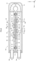
- FIG. 6 is a longitudinal cross-sectional view of a fluid sterilization device 10v of a second embodiment.
- the longitudinal cross section of FIG. 6 is a cross section taken in the direction in which the straight tubes 16a and 16b are arranged.
- the sterilization pipeline unit 60 refers to a structure in which the external connection tubes 14a and 14b are removed from the fluid sterilization device 10u of FIG. 3 .
- the fluid sterilization device 10v has a structure in which two sterilization pipeline units 60 are arranged in the X axis direction and are connected in series by a U-shaped tube 18v.
- the fluid path length is increased by connecting three or more sterilization pipeline units 60, so that the sterilization power can be further increased.
Landscapes
- Health & Medical Sciences (AREA)
- Life Sciences & Earth Sciences (AREA)
- Organic Chemistry (AREA)
- Epidemiology (AREA)
- Engineering & Computer Science (AREA)
- Environmental & Geological Engineering (AREA)
- Water Supply & Treatment (AREA)
- Chemical & Material Sciences (AREA)
- Toxicology (AREA)
- Hydrology & Water Resources (AREA)
- Animal Behavior & Ethology (AREA)
- General Health & Medical Sciences (AREA)
- Public Health (AREA)
- Veterinary Medicine (AREA)
- Apparatus For Disinfection Or Sterilisation (AREA)
- Physical Water Treatments (AREA)
Applications Claiming Priority (2)
| Application Number | Priority Date | Filing Date | Title |
|---|---|---|---|
| JP2022099469A JP2024000655A (ja) | 2022-06-21 | 2022-06-21 | 流体殺菌装置 |
| PCT/JP2023/020332 WO2023248749A1 (fr) | 2022-06-21 | 2023-05-31 | Dispositif de stérilisation de fluide |
Publications (2)
| Publication Number | Publication Date |
|---|---|
| EP4527418A1 true EP4527418A1 (fr) | 2025-03-26 |
| EP4527418A4 EP4527418A4 (fr) | 2025-07-16 |
Family
ID=89379867
Family Applications (1)
| Application Number | Title | Priority Date | Filing Date |
|---|---|---|---|
| EP23826936.9A Pending EP4527418A4 (fr) | 2022-06-21 | 2023-05-31 | Dispositif de stérilisation de fluide |
Country Status (5)
| Country | Link |
|---|---|
| US (1) | US20250325719A1 (fr) |
| EP (1) | EP4527418A4 (fr) |
| JP (1) | JP2024000655A (fr) |
| CN (1) | CN119317452A (fr) |
| WO (1) | WO2023248749A1 (fr) |
Family Cites Families (10)
| Publication number | Priority date | Publication date | Assignee | Title |
|---|---|---|---|---|
| GB1159306A (en) * | 1966-08-02 | 1969-07-23 | James William Harrison | Fluid Sterilisation Apparatus |
| GB0714363D0 (en) * | 2007-07-24 | 2007-09-05 | P W Circuits Ltd | Treatment apparatus |
| JP5674436B2 (ja) * | 2010-11-29 | 2015-02-25 | 前澤工業株式会社 | 紫外線照射水処理装置 |
| JP6180178B2 (ja) | 2013-05-13 | 2017-08-16 | 国立大学法人埼玉大学 | 紫外線照射水処理装置 |
| JP6373792B2 (ja) * | 2015-04-22 | 2018-08-15 | 日機装株式会社 | 殺菌装置 |
| JP6682347B2 (ja) * | 2016-05-16 | 2020-04-15 | 国立大学法人埼玉大学 | 水処理装置 |
| JP7270371B2 (ja) * | 2018-12-13 | 2023-05-10 | スタンレー電気株式会社 | 流体殺菌装置 |
| KR20200117577A (ko) * | 2019-04-05 | 2020-10-14 | 이상래 | 직수형 다중 유로구조를 갖는 자외선 살균 모듈 및 그 방법 |
| JP7370261B2 (ja) * | 2020-01-28 | 2023-10-27 | スタンレー電気株式会社 | 流体殺菌装置及び流体殺菌ユニット |
| JP7381365B2 (ja) * | 2020-02-26 | 2023-11-15 | メタウォーター株式会社 | 水処理装置 |
-
2022
- 2022-06-21 JP JP2022099469A patent/JP2024000655A/ja active Pending
-
2023
- 2023-05-31 EP EP23826936.9A patent/EP4527418A4/fr active Pending
- 2023-05-31 WO PCT/JP2023/020332 patent/WO2023248749A1/fr not_active Ceased
- 2023-05-31 CN CN202380044438.7A patent/CN119317452A/zh active Pending
- 2023-05-31 US US18/873,346 patent/US20250325719A1/en active Pending
Also Published As
| Publication number | Publication date |
|---|---|
| EP4527418A4 (fr) | 2025-07-16 |
| JP2024000655A (ja) | 2024-01-09 |
| CN119317452A (zh) | 2025-01-14 |
| US20250325719A1 (en) | 2025-10-23 |
| WO2023248749A1 (fr) | 2023-12-28 |
Similar Documents
| Publication | Publication Date | Title |
|---|---|---|
| CN110944679B (zh) | 流体消毒设备和方法 | |
| CN105209393B (zh) | 杀菌净化反应器 | |
| KR20180104039A (ko) | Uv-led 광반응기들에 대한 열 소산 장치들 및 방법들 | |
| CN207632549U (zh) | 流体杀菌装置 | |
| JP2018008213A (ja) | 流体殺菌装置 | |
| CN211797808U (zh) | 用于为穿流的流体消毒的装置 | |
| TW202100185A (zh) | 流體殺菌裝置 | |
| EP4527418A1 (fr) | Dispositif de stérilisation de fluide | |
| WO2017038764A1 (fr) | Dispositif de stérilisation | |
| KR20200039581A (ko) | 유체를 소독하기 위한 장치 어레인지먼트 및 유체 소독 장치 | |
| CN213326825U (zh) | 流体杀菌装置 | |
| US11985736B2 (en) | Fluid heating device | |
| JP7700936B2 (ja) | 流体殺菌装置 | |
| CN113995859A (zh) | 流体杀菌装置 | |
| CN210595371U (zh) | 一种过流水消毒器 | |
| KR20190119953A (ko) | 자외선 살균 장치 | |
| US20250187947A1 (en) | Fluid sterilization device | |
| WO2020183912A1 (fr) | Dispositif de stérilisation de fluide | |
| CN220520209U (zh) | 流体处理装置 | |
| JP3043543U (ja) | 液体加熱装置 | |
| JP2025040147A (ja) | 殺菌装置 | |
| JP7642112B1 (ja) | 流水殺菌装置 | |
| EP4292614A1 (fr) | Dispositif de stérilisation de fluide | |
| CN216273222U (zh) | 紫外线灯杀菌装置以及杀菌设备 | |
| KR102134678B1 (ko) | 가공 장비와 인라인 연결되는 액체 가열 장치 |
Legal Events
| Date | Code | Title | Description |
|---|---|---|---|
| STAA | Information on the status of an ep patent application or granted ep patent |
Free format text: STATUS: THE INTERNATIONAL PUBLICATION HAS BEEN MADE |
|
| PUAI | Public reference made under article 153(3) epc to a published international application that has entered the european phase |
Free format text: ORIGINAL CODE: 0009012 |
|
| STAA | Information on the status of an ep patent application or granted ep patent |
Free format text: STATUS: REQUEST FOR EXAMINATION WAS MADE |
|
| 17P | Request for examination filed |
Effective date: 20241218 |
|
| AK | Designated contracting states |
Kind code of ref document: A1 Designated state(s): AL AT BE BG CH CY CZ DE DK EE ES FI FR GB GR HR HU IE IS IT LI LT LU LV MC ME MK MT NL NO PL PT RO RS SE SI SK SM TR |
|
| REG | Reference to a national code |
Ref country code: DE Ref legal event code: R079 Free format text: PREVIOUS MAIN CLASS: A61L0002100000 Ipc: C02F0001320000 |
|
| STAA | Information on the status of an ep patent application or granted ep patent |
Free format text: STATUS: EXAMINATION IS IN PROGRESS |
|
| A4 | Supplementary search report drawn up and despatched |
Effective date: 20250616 |
|
| RIC1 | Information provided on ipc code assigned before grant |
Ipc: C02F 1/32 20230101AFI20250610BHEP Ipc: A61L 2/10 20060101ALI20250610BHEP |
|
| 17Q | First examination report despatched |
Effective date: 20250701 |
|
| DAV | Request for validation of the european patent (deleted) | ||
| DAX | Request for extension of the european patent (deleted) |