EP4520697A1 - Vorrats- und zuführanordnung für einen schweissdraht für eine schweiss- oder lötanlage - Google Patents
Vorrats- und zuführanordnung für einen schweissdraht für eine schweiss- oder lötanlage Download PDFInfo
- Publication number
- EP4520697A1 EP4520697A1 EP24197536.6A EP24197536A EP4520697A1 EP 4520697 A1 EP4520697 A1 EP 4520697A1 EP 24197536 A EP24197536 A EP 24197536A EP 4520697 A1 EP4520697 A1 EP 4520697A1
- Authority
- EP
- European Patent Office
- Prior art keywords
- wire
- drum
- storage
- lid
- feeding assembly
- Prior art date
- Legal status (The legal status is an assumption and is not a legal conclusion. Google has not performed a legal analysis and makes no representation as to the accuracy of the status listed.)
- Granted
Links
Images




Classifications
-
- B—PERFORMING OPERATIONS; TRANSPORTING
- B65—CONVEYING; PACKING; STORING; HANDLING THIN OR FILAMENTARY MATERIAL
- B65H—HANDLING THIN OR FILAMENTARY MATERIAL, e.g. SHEETS, WEBS, CABLES
- B65H49/00—Unwinding or paying-out filamentary material; Supporting, storing or transporting packages from which filamentary material is to be withdrawn or paid-out
- B65H49/02—Methods or apparatus in which packages do not rotate
- B65H49/04—Package-supporting devices
- B65H49/06—Package-supporting devices for a single operative package
- B65H49/08—Package-supporting devices for a single operative package enclosing the package
-
- B—PERFORMING OPERATIONS; TRANSPORTING
- B23—MACHINE TOOLS; METAL-WORKING NOT OTHERWISE PROVIDED FOR
- B23K—SOLDERING OR UNSOLDERING; WELDING; CLADDING OR PLATING BY SOLDERING OR WELDING; CUTTING BY APPLYING HEAT LOCALLY, e.g. FLAME CUTTING; WORKING BY LASER BEAM
- B23K9/00—Arc welding or cutting
- B23K9/12—Automatic feeding or moving of electrodes or work for spot or seam welding or cutting
- B23K9/133—Means for feeding electrodes, e.g. drums, rolls, motors
- B23K9/1336—Driving means
-
- B—PERFORMING OPERATIONS; TRANSPORTING
- B23—MACHINE TOOLS; METAL-WORKING NOT OTHERWISE PROVIDED FOR
- B23K—SOLDERING OR UNSOLDERING; WELDING; CLADDING OR PLATING BY SOLDERING OR WELDING; CUTTING BY APPLYING HEAT LOCALLY, e.g. FLAME CUTTING; WORKING BY LASER BEAM
- B23K3/00—Tools, devices or special appurtenances for soldering, e.g. brazing, or unsoldering, not specially adapted for particular methods
- B23K3/06—Solder feeding devices; Solder melting pans
- B23K3/0607—Solder feeding devices
- B23K3/063—Solder feeding devices for wire feeding
-
- B—PERFORMING OPERATIONS; TRANSPORTING
- B23—MACHINE TOOLS; METAL-WORKING NOT OTHERWISE PROVIDED FOR
- B23K—SOLDERING OR UNSOLDERING; WELDING; CLADDING OR PLATING BY SOLDERING OR WELDING; CUTTING BY APPLYING HEAT LOCALLY, e.g. FLAME CUTTING; WORKING BY LASER BEAM
- B23K9/00—Arc welding or cutting
- B23K9/12—Automatic feeding or moving of electrodes or work for spot or seam welding or cutting
- B23K9/133—Means for feeding electrodes, e.g. drums, rolls, motors
- B23K9/1333—Dereeling means
-
- B—PERFORMING OPERATIONS; TRANSPORTING
- B65—CONVEYING; PACKING; STORING; HANDLING THIN OR FILAMENTARY MATERIAL
- B65H—HANDLING THIN OR FILAMENTARY MATERIAL, e.g. SHEETS, WEBS, CABLES
- B65H51/00—Forwarding filamentary material
- B65H51/02—Rotary devices, e.g. with helical forwarding surfaces
- B65H51/04—Rollers, pulleys, capstans, or intermeshing rotary elements
- B65H51/08—Rollers, pulleys, capstans, or intermeshing rotary elements arranged to operate in groups or in co-operation with other elements
- B65H51/10—Rollers, pulleys, capstans, or intermeshing rotary elements arranged to operate in groups or in co-operation with other elements with opposed coacting surfaces, e.g. providing nips
-
- B—PERFORMING OPERATIONS; TRANSPORTING
- B65—CONVEYING; PACKING; STORING; HANDLING THIN OR FILAMENTARY MATERIAL
- B65H—HANDLING THIN OR FILAMENTARY MATERIAL, e.g. SHEETS, WEBS, CABLES
- B65H51/00—Forwarding filamentary material
- B65H51/14—Aprons, endless belts, lattices, or like driven elements
-
- B—PERFORMING OPERATIONS; TRANSPORTING
- B65—CONVEYING; PACKING; STORING; HANDLING THIN OR FILAMENTARY MATERIAL
- B65H—HANDLING THIN OR FILAMENTARY MATERIAL, e.g. SHEETS, WEBS, CABLES
- B65H57/00—Guides for filamentary materials; Supports therefor
- B65H57/18—Guides for filamentary materials; Supports therefor mounted to facilitate unwinding of material from packages
-
- B—PERFORMING OPERATIONS; TRANSPORTING
- B65—CONVEYING; PACKING; STORING; HANDLING THIN OR FILAMENTARY MATERIAL
- B65H—HANDLING THIN OR FILAMENTARY MATERIAL, e.g. SHEETS, WEBS, CABLES
- B65H2701/00—Handled material; Storage means
- B65H2701/30—Handled filamentary material
- B65H2701/36—Wires
Definitions
- the present invention relates to the field of wire welding or brazing plants and relates in particular to a storage and feeding assembly for a welding wire for welding or brazing plants.
- the present invention may however be used for any type of wire that has to be stored in a drum and supplied to a plant positioned downstream of the assembly.
- some welding or brazing plants use a welding wire stored in a drum.
- the wire is progressively extracted from the drum and supplied to the welding apparatus, for example a welding torch moved either by a robot or manually.
- FIG. 1 An example of a storage and feeding assembly typical of the prior art is shown in Fig. 1 , wherein a welding wire wound in coils is stored in a cylindrical drum closed by a conical lid.
- This conical lid which has a wire outlet passage at the top thereof, also has the function of guiding the wire towards the outlet passage in such a way as to limit the formation of kinks.
- the wire is pulled out of the drum and fed to the welding apparatus by a wire pulling device.
- the wire pulling device is also associated with a wire straightening device that is suitable for eliminating, or at least reducing, the tendency of the wire to twist due to the prolonged storage thereof in the form of coils in the drum.
- the bundle of wire does not occupy all the available volume of the drum, due both to the requirement to position, at the top of the bundle of wire, unwinding accessories to facilitate unwinding the wire towards the exit passage, and also to avoid forcing the wire to complete an overly pronounced curve upwards (exit angle ⁇ in Fig. 1 ), that may facilitate the formation of kinks in unwinding the wire.
- the object of the present invention is that of proposing a storage and feeding assembly of a wire, wound in a coil, in a drum that makes it possible to store a greater quantity of wire in the drum, thus reducing the drum replacement frequency and increasing productivity.
- the numeral 1 has been used to denote, as a whole, a storage and feeding assembly for a welding wire to be supplied to an apparatus, such as a welding torch, according to the invention.
- the storage and feeding assembly 1 extends along an assembly axis X-X.
- the storage and feeding assembly 1 comprises a drum 2, for example cylindrical in shape or with a polygonal cross section, that is suitable for storing a welding wire 10 wound in coils 10', forming a bundle 12 of wire.
- the coils 10' of the wire 10 are maintained in an ordered overlapping relationship that allows the correct extraction of the welding wire 10 from the drum 2.
- the drum extends about a drum axis Y-Y between a resting base 21 and an open upper end 23.
- the assembly axis X-X and the drum axis Y-Y are aligned.
- the ratio between a longitudinal dimension of the drum 2 and a longitudinal dimension of the bundle 12 is between 70% and 100%, preferably 85%.
- longitudinal dimension refers to the dimension along the drum axis Y-Y.
- the storage and feeding assembly 1 comprises a wire handling device 3 positioned between the drum 2 and the apparatus and suitable for extracting the wire from the drum 2 in order to feed it to the welding or brazing apparatus (not shown).
- the wire handling device 3 comprises a wire rectifier group 50 and/or a wire pulling group 60.
- the wire pulling group 60 comprises two opposing driving belts 12, 12'.
- the two driving belts form two respective straight belt segments 14 facing each other so as to receive therebetween and move the wire 10 exiting from the drum 2.
- each driving belt 12; 12' is returned by respective tensile rollers 13; 13' in such a way as to form a closed ring.
- One of such tensile rollers 13, 13' is a drive roller suitable for generating the rotation of the respective driving belt 12; 12'.
- the drive roller is keyed to a shaft of an actuator 17, for example a pneumatic or electric actuator.
- each driving belt 12; 12' is returned on three tensile rollers 13; 13'.
- the extension of the straight segment 14 is at least equal to the diameter of the tensile rollers 13; 13', i.e., it is on the order of tens or, preferably, hundreds of mm.
- the driving belts 12; 12' having a much larger contact surface with the wire than the rollers, exert a much lower specific pressure.
- the welding wire 10 is therefore not deformed by the passage between the driving belts 12; 12', and also any deposit of dust or other external agents on the belts has no effect on the surface of the wire.
- the driving belts 12; 12' may be made of a softer material than the one with which the driving rollers are usually made.
- the tensile rollers 13; 13' of the two opposite driving belts 12; 12' are supported by respective driving plates 120; 120' that may be mutually spaced apart, for example by means of micrometric screws 122, as a function of the diameter of the welding wire 1.
- the wire pulling group 60 comprises a plurality of motorized wire pulling rollers facing each other so as to receive therebetween and move the wire 10 exiting from the drum 2.
- the wire pulling group 60 comprises a plurality of motorized wire pulling rollers facing each other so as to receive therebetween and move the wire 10 exiting from the drum 2.
- the rectifier group 50 which as mentioned above may be positioned downstream or upstream of the wire pulling group 60, comprises at least two roller rectifier units 52, 52a arranged in series with each other along the advancement direction of the wire.
- Each rectifier unit 52; 52a comprises at least two opposing straightening rollers 54, 54'; 54a, 54a' between which the welding wire 10 is made to pass, being moved by the wire pulling group 60.
- the suitably shaped straightening rollers 54, 54' of one rectifier unit 52 are oriented perpendicular to the straightening rollers 54a, 54a' of at least one other rectifier unit 52a. However, all of the straightening rollers 54, 54'; 54a, 54a' have the respective rotation axes thereof perpendicular to the advancement direction of the welding wire 10, i.e., perpendicular to the straight segments 14 of the driving belts 12, 12'.
- the straightening rollers 54, 54'; 54a, 54a' are mounted idly on a respective roller support plate 56, 56a. Therefore, the straightening rollers effectively perform only the function of straightening the welding wire 10. By not exerting any torque on the wire, the wire is straightened, but the cross section thereof is not deformed nor is the surface thereof altered.
- each rectifier unit 52, 52a is provided with at least five straightening rollers 54, 54'; 54a, 54a': at least two first rollers 54; 54a arranged side by side along the advancement direction of the wire, opposite and offset with respect to at least three second rollers 54'; 54a' arranged side by side along the advancement direction of the wire.
- the straightening rollers of each rectifier unit are seven in number: three first rollers 54; 54a arranged side by side along the advancement direction of the wire, opposite and offset with respect to four second rollers 54'; 54a' arranged side by side along the advancement direction of the wire.
- the distance between the first and second straightening rollers 54, 54'; 54a, 54a' may be adjusted as a function of the diameter of the necessary deformation of the welding wire 10.
- the storage and feeding assembly 1 comprises a substantially conical lid 5, wherein an outlet passage 5' of the wire 10 is obtained at the top thereof.
- the lid side wall 55 is at least partially made of a transparent material in such a way as to allow for visual inspection of the handling device 3 through the lid side wall.
- the lid side wall 55 is made entirely of a transparent material.
- the entire lid 5 is made of a transparent material.
- the lid 5 is made of a plastics material.
- the storage and feeding assembly 1 comprises a spacer 4 suitable for being releasably positioned between the upper end 23 of the drum 2 and the lid 5.
- the spacer comprises a spacer body 40 that defines a spacer housing 400 delimited by an annular side wall 42 in such a way as to act as an extension for the drum 2.
- the annular side wall 42 is made at least partially of a transparent material in such a way as to allow for a visual inspection of the spacer housing 400 through the annular side wall 42.
- the annular side wall 42 is made entirely of a transparent material.
- the entire spacer body 40 is made of a transparent material.
- the spacer body 40 is made of a plastics material.
- the spacer 4 is placed at the end of the drum 2.
- a spacer outlet opening 4' is obtained in the spacer 4 through which the wire 10 originating from the drum 2 emerges.
- the spacer body 40 further comprises an upper base 44 connected to the annular side wall 42.
- the annular side wall 42 and the upper base 44 define the spacer housing 400.
- the spacer outlet opening 4' is obtained in the upper base 44.
- the wire handling device 3 is integrally fastened to the upper base 44, in particular externally with respect to the spacer housing 400.
- the wire handling device 3 is screwable to the spacer 4, preferably to the upper base 44.
- the wire handling device 3 comprises a support base 30 that is suitable for supportingly engaging and being fastened to the spacer 4, preferably to the upper base 44.
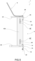
- Fig. 3 schematically shows the storage and feeding assembly 1 wherein the welding wire 10 of the upper coil, emerging from the drum outlet opening 2', passes through the spacer housing 400 and exits from the spacer outlet opening 4', preferably obtained in the upper base 44, and is engaged by the wire handling device 3.
- the annular side wall 42 comprises plate-shaped elements 42a and vertical supports 42b interposed therebetween.
- spacer openings 42' are obtained for accessing the spacer housing 400 when the spacer 4 engages the drum 2.
- openings 42' may be opened and closed by means of a door 42".
- the door 42" is made of a transparent material.
- the annular side wall 42 has an adjustable axial extension.
- "Axial extension" means along the assembly axis X-X.
- the annular side wall 42 is adjustable; for example it is a telescopic wall.
- the spacer body 40 comprises a lower flange 46 for the engagement with the drum 2.
- the lower flange 46 rests against an upper edge 20 of the drum 2.
- the annular side wall 42 preferably the vertical supports 42b, comprises upper longitudinal holes 48' and lower longitudinal holes 48" for the engagement, by means of screws 49, with the upper base 44 and the lower flange 46 respectively.
- the storage and feeding assembly 1 comprises first coupling means 15 for releasably coupling the spacer 4 to the drum 2.
- the first coupling means 15 comprise a first releasable clamping ring 16 that couples adjacent end portions of the drum 2 and of the annular side wall 42.
- the first clamping ring 16 has a C-shaped cross section.
- the first clamping ring 16 comprises first handling means 160 suitable for configuring the first clamping ring 16 from an open configuration to a closed configuration wherein it engages the adjacent end portions of the drum 2 and of the annular side wall 42 in order to fasten them in a stable manner to each other.
- a lower end portion of the annular side wall 42 comprises a lower circumferential groove 14 for engagement with the first clamping ring 16.
- the lower circumferential groove 14 is obtained only at the vertical supports 42b.
- the upper end 23 of the drum 2 comprises a circumferential drum groove 22 for engagement with the first clamping ring 16.
- the first clamping ring 16 is partially inserted into the lower circumferential groove 14 of the annular side wall 42, and into the circumferential drum groove 22 of the drum 2.
- the lid 5, positioned on the spacer 4, preferably on the upper base 44, defines a lid volume 500.
- the lid 5 comprises an upper lid wall 50 wherein there are obtained the outlet passage 5', and a lid side wall 55.
- the handling device 3 extends into the lid volume 500 substantially coaxially to the drum axis Y-Y.
- the wire handling device 3 is positioned downstream of the lid 5 along the wire feed direction to the apparatus.
- the wire handling device 3 is positioned externally to the lid 5, it is, for example, integrally fastened to the upper lid wall 50, externally in relation to the lid volume 500.
- lid openings 55' are obtained in the lid side wall 55 in order to access the lid volume 500 when the lid 5 engages with the spacer 4.
- openings 55' may be opened and closed by means of a door 55".
- the door 55" is made of a transparent material.
- the storage and feeding assembly 1 comprises second coupling means 25 for coupling the lid 5 to the spacer 4.
- the second coupling means 25 comprise a second releasable clamping ring 26 that couples adjacent end portions of the annular side wall 42 and the lid 5.
- the second clamping ring 26 has a C-shaped cross section.
- the second clamping ring 26 comprises second handling means 260 that are suitable for configuring the second clamping ring 26 from an open configuration to a closed configuration wherein it engages the adjacent end portions of the annular side wall 42 and of the lid 5 in order to fasten them in a stable manner to each other.
- an upper end portion of the ring body 40 comprises an upper circumferential groove 24 for engagement with the second clamping ring 26.
- the upper circumferential groove 24 is obtained only at the vertical supports 42b.
- the second clamping ring 26 engages the annular side wall 42, preferably the vertical supports 42b and the lid 5, preferably the lid side wall 55.
- the second clamping ring 26 is partially inserted into the upper circumferential groove 24 of the annular side wall 42.
- the storage and feeding assembly 1 comprises at least one wire end sensor, which may be positioned, with respect to the wire supply direction, downstream and/or upstream of the wire handling device 3.
- the at least one wire end sensor may be positioned between the rectifier group and the wire pulling group, or before and/or after each of the rectifier group and the wire pulling group.
- the storage and feeding assembly 1 comprises at least one wire unwinding accessory 100 positioned at least partially in the spacer housing 400.
- the accessory 100 is a wire guide device 110 ( Fig. 6d ), also known in the jargon as a "pay-off system," which allows the welding wire 10 to exit the drum 2 correctly.
- wire guide device generally has a conical shape and comprises a base that rests above the coils 10' of the wire and a rotating tubular element which guides the wire of the upper coil towards the drum outlet opening 2'.
- Fig. 1 schematically shows the storage and feeding assembly typical of the prior art, wherein the lid is directly engaged with the drum, and the wire handling device is external to the lid.
- the welding wire originating from the upper coil, towards the wire handling device forms an angle ⁇ with a transverse axis with respect to the assembly axis.
- Fig. 3 shows, on the other hand, the storage and feeding assembly 1 of the present invention which comprises the spacer 4, placed between the drum 2 and the lid 5, and wherein the wire handling device 3 is preferably inserted inside the lid 5.
- the welding wire 10 originating from the upper coil towards the wire handling device 3 forms an angle ⁇ with a transverse axis with respect to the assembly axis X-X.
- angle ⁇ is greater than the angle ⁇ , thus in the storage and feeding assembly of the present invention, the wire has a lower possibility of tangling and deformation than the wire of the storage and feeding assembly of the prior art.
- using the spacer allows a greater angle of exit of the wire from the drum, thus decreasing the tangling and deformation of the wire.
- the upper base of the spacer, to which the wire handling device is fastened, prevents debris, such as dust, from entering the drum thereby damaging the stored wire.
- the use of the lid makes it possible to protect the wire handling device furthermore preventing the operator from being exposed to accidental injury, such as injury caused by electric shock due to unwanted voltage losses.
- the openings obtained in the spacer and in the lid may be secured in such a way that only specialized personnel may have access thereto, thereby avoiding tampering and/or accidental injury by the operators.
Landscapes
- Engineering & Computer Science (AREA)
- Mechanical Engineering (AREA)
- Physics & Mathematics (AREA)
- Plasma & Fusion (AREA)
- Storage Of Web-Like Or Filamentary Materials (AREA)
- Unwinding Of Filamentary Materials (AREA)
Applications Claiming Priority (1)
| Application Number | Priority Date | Filing Date | Title |
|---|---|---|---|
| IT202300018489 | 2023-09-08 |
Publications (2)
| Publication Number | Publication Date |
|---|---|
| EP4520697A1 true EP4520697A1 (de) | 2025-03-12 |
| EP4520697B1 EP4520697B1 (de) | 2026-08-05 |
Family
ID=88838945
Family Applications (1)
| Application Number | Title | Priority Date | Filing Date |
|---|---|---|---|
| EP24197536.6A Active EP4520697B1 (de) | 2023-09-08 | 2024-08-30 | Vorrats- und zuführanordnung für einen schweissdraht für eine schweiss- oder lötanlage |
Country Status (5)
| Country | Link |
|---|---|
| US (1) | US20250083248A1 (de) |
| EP (1) | EP4520697B1 (de) |
| CN (1) | CN119589054A (de) |
| CA (1) | CA3245392A1 (de) |
| MX (1) | MX2024010911A (de) |
Citations (8)
| Publication number | Priority date | Publication date | Assignee | Title |
|---|---|---|---|---|
| JPS57193682U (de) * | 1981-06-04 | 1982-12-08 | ||
| JPS598965U (ja) * | 1982-07-06 | 1984-01-20 | 株式会社神戸製鋼所 | 溶接用ワイヤ収納パツク |
| JPS5933862U (ja) * | 1982-08-26 | 1984-03-02 | 住友電気工業株式会社 | パツク巻線の高速サプライ装置 |
| WO1988010230A1 (en) * | 1987-06-22 | 1988-12-29 | British Telecommunications Public Limited Company | Fibre coiling |
| JP2003025068A (ja) * | 2001-07-11 | 2003-01-28 | Kobe Steel Ltd | 溶接ワイヤ用容器 |
| KR200400806Y1 (ko) * | 2005-08-17 | 2005-11-09 | 고려용접봉 주식회사 | 페일팩의 헤드캡 |
| KR20140005881U (ko) * | 2013-05-09 | 2014-11-20 | 현대중공업 주식회사 | 페일 팩 와이어 고정장치 |
| WO2018167806A1 (en) | 2017-03-16 | 2018-09-20 | Safra S.P.A. | Wire straightening device for a welding or brazing plant |
Family Cites Families (23)
| Publication number | Priority date | Publication date | Assignee | Title |
|---|---|---|---|---|
| US2389529A (en) * | 1944-08-26 | 1945-11-20 | Int Harvester Co | Wire container |
| US3809333A (en) * | 1972-04-03 | 1974-05-07 | Teledyne Inc | Dispensing container for wire or the like |
| US5810283A (en) * | 1996-08-16 | 1998-09-22 | United Technologies Automotive, Inc. | Apparatus and method for wire coil payoff |
| CN1095801C (zh) * | 1998-01-29 | 2002-12-11 | 日铁溶接工业株式会社 | 焊接用焊丝的包装物 |
| US6126102A (en) * | 1998-11-10 | 2000-10-03 | E. I. Du Pont De Nemours And Company | Apparatus for high speed beaming of elastomeric yarns |
| KR100463375B1 (ko) * | 2000-12-23 | 2004-12-29 | 현대종합금속 주식회사 | 결합과 해체가 용이한 용접용 와이어 수납용기 |
| US6715608B1 (en) * | 2001-11-06 | 2004-04-06 | Lincoln Global, Inc. | Package for welding wire |
| WO2004000499A1 (en) * | 2002-06-22 | 2003-12-31 | Hyundai Welding Co., Ltd. | A pail pack and a welding wire package using it |
| US20080156925A1 (en) * | 2007-01-03 | 2008-07-03 | Elco Enterprises, Inc. | Wire Dispensing System |
| US7866586B2 (en) * | 2007-08-30 | 2011-01-11 | Lincoln Global, Inc. | Wire guide insert and method for drum package payoff |
| KR100912861B1 (ko) * | 2007-10-29 | 2009-08-19 | 현대종합금속 주식회사 | 용접와이어 엉킴방지장치 |
| US7938352B2 (en) * | 2009-03-10 | 2011-05-10 | Lincoln Global, Inc. | Wire dispensing apparatus for packaged wire |
| US8381906B2 (en) * | 2011-05-23 | 2013-02-26 | Linclon Global, Inc. | Bulk wire dampening apparatus and method |
| US8662003B1 (en) * | 2011-05-27 | 2014-03-04 | Edward L. Cooper | Wire level gauge |
| US8936210B2 (en) * | 2011-11-16 | 2015-01-20 | Illinois Tool Works Inc. | Floating dispensing mechanism for drum packed welding wire |
| US9421633B2 (en) * | 2012-10-09 | 2016-08-23 | Lincoln Global, Inc. | Bulk wire delivery system |
| US9975728B2 (en) * | 2015-09-10 | 2018-05-22 | Sidergas Spa | Wire container lid, wire container and wire feeding system |
| US11059691B2 (en) * | 2019-06-07 | 2021-07-13 | Plasticos y Alambres, S.A. DE C.V. | Container with anti-wire-entangling device for packaging and paying out coiled welding wire |
| KR102358618B1 (ko) * | 2020-08-20 | 2022-02-07 | 고려용접봉 주식회사 | 용접 와이어 리테이너 링 |
| US12415703B2 (en) * | 2020-08-27 | 2025-09-16 | A.B. Carter, Inc. | Canister-yarn tensioning assembly incorporating a pivoted yarn tensioner |
| US12466691B2 (en) * | 2020-09-09 | 2025-11-11 | Kobe Steel, Ltd. | Kink prevention jig and pail pack |
| CN115283793B (zh) * | 2022-10-08 | 2022-12-20 | 博顿液压股份有限公司 | 一种用于液压缸加工的焊接送丝设备 |
| WO2024173301A1 (en) * | 2023-02-13 | 2024-08-22 | Cerro Wire Llc | Barrel for storing conductors or wires |
-
2024
- 2024-08-30 EP EP24197536.6A patent/EP4520697B1/de active Active
- 2024-09-03 CA CA3245392A patent/CA3245392A1/en active Pending
- 2024-09-05 MX MX2024010911A patent/MX2024010911A/es unknown
- 2024-09-05 CN CN202411243360.4A patent/CN119589054A/zh active Pending
- 2024-09-09 US US18/828,283 patent/US20250083248A1/en active Pending
Patent Citations (8)
| Publication number | Priority date | Publication date | Assignee | Title |
|---|---|---|---|---|
| JPS57193682U (de) * | 1981-06-04 | 1982-12-08 | ||
| JPS598965U (ja) * | 1982-07-06 | 1984-01-20 | 株式会社神戸製鋼所 | 溶接用ワイヤ収納パツク |
| JPS5933862U (ja) * | 1982-08-26 | 1984-03-02 | 住友電気工業株式会社 | パツク巻線の高速サプライ装置 |
| WO1988010230A1 (en) * | 1987-06-22 | 1988-12-29 | British Telecommunications Public Limited Company | Fibre coiling |
| JP2003025068A (ja) * | 2001-07-11 | 2003-01-28 | Kobe Steel Ltd | 溶接ワイヤ用容器 |
| KR200400806Y1 (ko) * | 2005-08-17 | 2005-11-09 | 고려용접봉 주식회사 | 페일팩의 헤드캡 |
| KR20140005881U (ko) * | 2013-05-09 | 2014-11-20 | 현대중공업 주식회사 | 페일 팩 와이어 고정장치 |
| WO2018167806A1 (en) | 2017-03-16 | 2018-09-20 | Safra S.P.A. | Wire straightening device for a welding or brazing plant |
Also Published As
| Publication number | Publication date |
|---|---|
| CA3245392A1 (en) | 2025-06-04 |
| EP4520697B1 (de) | 2026-08-05 |
| MX2024010911A (es) | 2025-04-02 |
| US20250083248A1 (en) | 2025-03-13 |
| CN119589054A (zh) | 2025-03-11 |
Similar Documents
| Publication | Publication Date | Title |
|---|---|---|
| EP3595828B1 (de) | Drahtrichtvorrichtung für eine schweiss- oder lötanlage | |
| EP1154859B1 (de) | Kompaktes spulengatter | |
| US4022396A (en) | Interconnected stacked coils for continuous feed | |
| KR960701247A (ko) | 원통형 코러 둘레에 편평한 리본들을 배치하는 방법 및 장치(method and apparatus for applying flat ribbons about a cylindrical core) | |
| US20250083248A1 (en) | Storage and feeding assembly for a welding wire for a welding or brazing plant | |
| DE102016205056B4 (de) | Drahtum- oder -abspulanlage | |
| EP3597804B1 (de) | Fadenspannungsbeeinflussungseinrichtung für eine zwirn- oder kabliermaschine | |
| SE456086B (sv) | Anordning for att leda en tradspole till ett bearbetningsstelle | |
| US20250100058A1 (en) | Storage and feeding assembly for a welding wire for a welding or brazing plant | |
| EP2549002B1 (de) | Garnbehandlungskammer | |
| DE2744424B2 (de) | Spiniunaschinenrahmen | |
| DE1452277B2 (de) | Blechband-Abhaspelvorrichtung | |
| EP2718215A1 (de) | Zugwerk für den transport von filamenten | |
| DE102014014998A1 (de) | Spulstelle mit einer Ausrichteinrichtung für einen Spinnkops | |
| RU2203755C2 (ru) | Способ изготовления металлических трубок малого диаметра и большой длины и установка для его осуществления | |
| JPH08151169A (ja) | マルチプル・ヤーン・スタンド | |
| ITMI950748A1 (it) | Apparecchiatura di raddrizzamento di fili metallici con filiere a lunga durata | |
| DE102017129582A1 (de) | Fadenspleißvorrichtung für eine Textilmaschine | |
| DE3817678C1 (en) | Cabling machine for double twisting - has supporting cross wall on machine frame after every second spindle | |
| JP3552902B2 (ja) | 溶接ワイヤ矯正方法 | |
| DE202023107568U1 (de) | Lager- und Zuführungsanordnung für Schweiß- oder Lötdraht für eine Schweiß- oder Lötanlage | |
| EP1279635B1 (de) | Anlage zum Wickeln eines Profilstranges auf eine Spule | |
| KR100970912B1 (ko) | 코일 엉킴 방지장치 | |
| DE1815818C3 (de) | Vorrichtung zum Trennen nicht einwandfreien Garnes (Abfallgarnes) von einwandfrei verstrecktem Garn an Streckzwirnmaschinen und dgl | |
| JPH11180639A (ja) | 電線絡み低減装置 |
Legal Events
| Date | Code | Title | Description |
|---|---|---|---|
| PUAI | Public reference made under article 153(3) epc to a published international application that has entered the european phase |
Free format text: ORIGINAL CODE: 0009012 |
|
| STAA | Information on the status of an ep patent application or granted ep patent |
Free format text: STATUS: THE APPLICATION HAS BEEN PUBLISHED |
|
| AK | Designated contracting states |
Kind code of ref document: A1 Designated state(s): AL AT BE BG CH CY CZ DE DK EE ES FI FR GB GR HR HU IE IS IT LI LT LU LV MC ME MK MT NL NO PL PT RO RS SE SI SK SM TR |
|
| STAA | Information on the status of an ep patent application or granted ep patent |
Free format text: STATUS: REQUEST FOR EXAMINATION WAS MADE |
|
| 17P | Request for examination filed |
Effective date: 20250904 |
|
| STAA | Information on the status of an ep patent application or granted ep patent |
Free format text: STATUS: EXAMINATION IS IN PROGRESS |
|
| 17Q | First examination report despatched |
Effective date: 20251217 |
|
| GRAP | Despatch of communication of intention to grant a patent |
Free format text: ORIGINAL CODE: EPIDOSNIGR1 |
|
| STAA | Information on the status of an ep patent application or granted ep patent |
Free format text: STATUS: GRANT OF PATENT IS INTENDED |
|
| INTG | Intention to grant announced |
Effective date: 20260507 |
|
| GRAS | Grant fee paid |
Free format text: ORIGINAL CODE: EPIDOSNIGR3 |
|
| GRAA | (expected) grant |
Free format text: ORIGINAL CODE: 0009210 |
|
| STAA | Information on the status of an ep patent application or granted ep patent |
Free format text: STATUS: THE PATENT HAS BEEN GRANTED |
|
| AK | Designated contracting states |
Kind code of ref document: B1 Designated state(s): AL AT BE BG CH CY CZ DE DK EE ES FI FR GB GR HR HU IE IS IT LI LT LU LV MC ME MK MT NL NO PL PT RO RS SE SI SK SM TR |
|
| REG | Reference to a national code |
Ref country code: CH Ref legal event code: F10 Free format text: ST27 STATUS EVENT CODE: U-0-0-F10-F00 (AS PROVIDED BY THE NATIONAL OFFICE) Effective date: 20260805 |