EP4518162A2 - Annäherung von abtastwerten eines digitalen signals, die eine anzahl von signifikanten bits entsprechend den werten der abtastwerte reduziert - Google Patents
Annäherung von abtastwerten eines digitalen signals, die eine anzahl von signifikanten bits entsprechend den werten der abtastwerte reduziert Download PDFInfo
- Publication number
- EP4518162A2 EP4518162A2 EP25151379.2A EP25151379A EP4518162A2 EP 4518162 A2 EP4518162 A2 EP 4518162A2 EP 25151379 A EP25151379 A EP 25151379A EP 4518162 A2 EP4518162 A2 EP 4518162A2
- Authority
- EP
- European Patent Office
- Prior art keywords
- significant bits
- digital signal
- value
- sample
- signal
- Prior art date
- Legal status (The legal status is an assumption and is not a legal conclusion. Google has not performed a legal analysis and makes no representation as to the accuracy of the status listed.)
- Pending
Links
Images


Classifications
-
- G—PHYSICS
- G06—COMPUTING OR CALCULATING; COUNTING
- G06F—ELECTRIC DIGITAL DATA PROCESSING
- G06F17/00—Digital computing or data processing equipment or methods, specially adapted for specific functions
- G06F17/10—Complex mathematical operations
- G06F17/15—Correlation function computation including computation of convolution operations
-
- G—PHYSICS
- G06—COMPUTING OR CALCULATING; COUNTING
- G06F—ELECTRIC DIGITAL DATA PROCESSING
- G06F7/00—Methods or arrangements for processing data by operating upon the order or content of the data handled
- G06F7/38—Methods or arrangements for performing computations using exclusively denominational number representation, e.g. using binary, ternary, decimal representation
- G06F7/48—Methods or arrangements for performing computations using exclusively denominational number representation, e.g. using binary, ternary, decimal representation using non-contact-making devices, e.g. tube, solid state device; using unspecified devices
- G06F7/499—Denomination or exception handling, e.g. rounding or overflow
- G06F7/49942—Significance control
-
- H—ELECTRICITY
- H03—ELECTRONIC CIRCUITRY
- H03M—CODING; DECODING; CODE CONVERSION IN GENERAL
- H03M1/00—Analogue/digital conversion; Digital/analogue conversion
- H03M1/66—Digital/analogue converters
- H03M1/70—Automatic control for modifying converter range
-
- H—ELECTRICITY
- H03—ELECTRONIC CIRCUITRY
- H03M—CODING; DECODING; CODE CONVERSION IN GENERAL
- H03M7/00—Conversion of a code where information is represented by a given sequence or number of digits to a code where the same, similar or subset of information is represented by a different sequence or number of digits
- H03M7/30—Compression; Expansion; Suppression of unnecessary data, e.g. redundancy reduction
- H03M7/3059—Digital compression and data reduction techniques where the original information is represented by a subset or similar information, e.g. lossy compression
-
- H—ELECTRICITY
- H03—ELECTRONIC CIRCUITRY
- H03M—CODING; DECODING; CODE CONVERSION IN GENERAL
- H03M7/00—Conversion of a code where information is represented by a given sequence or number of digits to a code where the same, similar or subset of information is represented by a different sequence or number of digits
- H03M7/30—Compression; Expansion; Suppression of unnecessary data, e.g. redundancy reduction
- H03M7/60—General implementation details not specific to a particular type of compression
- H03M7/6047—Power optimization with respect to the encoder, decoder, storage or transmission
-
- G—PHYSICS
- G10—MUSICAL INSTRUMENTS; ACOUSTICS
- G10L—SPEECH ANALYSIS TECHNIQUES OR SPEECH SYNTHESIS; SPEECH RECOGNITION; SPEECH OR VOICE PROCESSING TECHNIQUES; SPEECH OR AUDIO CODING OR DECODING
- G10L19/00—Speech or audio signals analysis-synthesis techniques for redundancy reduction, e.g. in vocoders; Coding or decoding of speech or audio signals, using source filter models or psychoacoustic analysis
- G10L19/04—Speech or audio signals analysis-synthesis techniques for redundancy reduction, e.g. in vocoders; Coding or decoding of speech or audio signals, using source filter models or psychoacoustic analysis using predictive techniques
- G10L19/16—Vocoder architecture
- G10L19/18—Vocoders using multiple modes
- G10L19/24—Variable rate codecs, e.g. for generating different qualities using a scalable representation such as hierarchical encoding or layered encoding
-
- H—ELECTRICITY
- H03—ELECTRONIC CIRCUITRY
- H03M—CODING; DECODING; CODE CONVERSION IN GENERAL
- H03M7/00—Conversion of a code where information is represented by a given sequence or number of digits to a code where the same, similar or subset of information is represented by a different sequence or number of digits
- H03M7/30—Compression; Expansion; Suppression of unnecessary data, e.g. redundancy reduction
- H03M7/3068—Precoding preceding compression, e.g. Burrows-Wheeler transformation
- H03M7/3071—Prediction
- H03M7/3073—Time
Definitions
- the present invention relates to the field of digital signal processing. More specifically, it relates to approximations of samples of a digital signal.
- signals are commonly represented, used and modified in a digital form. It is for example the case of visual or image signals, which are usually represented in the form of digital matrixes representing the amplitude of luminosity of pixels for one or more color layers, and for audio signals, which are usually represented, for one or more audio channels, by a succession of temporal samples of amplitude of an audio track on each audio channel.
- a digital signal may be considered as being formed of samples which are stored on a number of bits, called bit depth of the signal.
- bit depth of the signal For example, an audio signal nowadays usually has a bit depth of 16 or 24 bits, while an image signal usually has a bit depth comprised between 8 and 16 bits.
- the resulting output digital signal When a filter, transform, transfer function, or convolution is applied to an input digital signal, the resulting output digital signal usually has a bit depth higher than the bit depth of the input digital signal, in order to preserve as much information as possible from the input digital signal, and the transform.
- the result of an attenuation of a 16 bit input digital signal can be stored on 24, or 32 bits, in order to have as much precision as possible in the output digital signal.
- the number of bits which are commonly used by computing capacities for calculating operations is generally much higher than the number of bits which are used to store digital signals. For example, most processors perform operations on 32 or 64 bits, while most audio signal have a bit depth of 16, and most image signals a bit depth of 8. This property is used by digital signal processing systems, to obtain a precision as high as possible. An attenuation of a signal is usually expressed in dB. A commonplace operation of audio processing consists of applying a gain, expressed in dB, to audio signals. The number of bits allowed by processing capabilities is widely used to obtain very precise values of amplitude change of an audio signal. In a similar manner, when applying a FIR (Finite Impulse Response) filter, a maximum number of bits is used, in order to obtain an impulse response of the FIR filter, which is as close as possible to a theoretical/ideal impulse response.
- FIR Finite Impulse Response
- an output signal needs to be processed in order to be provided to a user.
- an audio output digital signal can be converted to an analog signal by a Digital-to-Analog Converter (DAC) to be listened to using loudspeakers.
- DAC Digital-to-Analog Converter
- an image output digital signal can be viewed for example by activating pixels with level of luminosity defined by the values of samples of the output digital signal.
- Other forms of processing of a digital signal are possible.
- a digital signal may be compressed, in order to reduce the amount of data used to represent the signal.
- the signal may also be played using a player.
- a common assumption regarding signal processing consists in using the high number of bits allowed by modern processors to process digital signals with the highest number of bits available, because it is admitted that a higher number of bits is generally considered as providing an increased accuracy for processing signals.
- the processing of digital signal using the highest available number of bit often counterintuitively leads to a deterioration of the subjective perception of quality of the signal by users.
- Such deterioration may be caused by an inability of the processing unit to process the least significant parts of a signal properly (for example an limitation of the DAC that is actually not able to process a signal at its nominal bit depth with maximum precision, or a limitation of the input of an audio player).
- the digital signal may be truncated to the expected bit depth of the processing unit when supplying the digital signal to the processing unit, but this does not prevent the deterioration.
- the invention discloses a digital circuitry configured to calculate, from at least a value of a first sample of a first digital signal, a value of a second sample of a second digital signal, based on the value of the first sample, said value of the second sample having a second number of significant bits lower than a first number of significant bits of the value of the first sample, said second number of significant bits depending at least on the value of the first sample.
- the second number of significant bits is defined according to the value the first sample, so that the second number of significant bits varies in a direction opposite to a direction of variation of the absolute value of the first sample.
- the second number of significant bits is equal to the minimum of a first predefined number minus a rounding of a binary logarithm of the absolute value of the first sample, and a second predefined number.
- the second number of significant bits is obtained using: a third predefined number lower than the bit depth of the first digital signal; a fourth predefined number higher than 1 and lower than the bit depth of the first digital signal minus the third predefined number; a fifth predefined number higher than or equal to 1, and lower than or equal to the bit depth of the first digital signal minus the third predefined number minus the fourth predefined number plus 1; by: identifying the highest integer number between 0 and the fourth predefined number , for which the first integer number is lower than: two raised to the power of the bit depth of the first digital signal minus one multiplied by two raised to the power of 1 minus the fifth predefined number minus said highest number; setting the second number of significant bits as the third predefined number plus said highest integer number.
- the second number of significant bits is defined according to a predicted difference between the value of the first sample and an approximation of the first sample using a third number of significant bits, so that the second number of significant bits varies in the same direction than the direction of variation of the absolute value of said predicted difference.
- the second number of significant bits is defined as a growing function of said predicted difference divided by the value of the first sample.
- the second number of significant bits depends upon values of coefficients obtained by a frequency transform of a time window of samples of the first digital signal comprising the first sample.
- the second number of significant bits is defined according to a value representative of a derivative of the first digital signal at the first sample.
- the value representative of the derivative of the first digital signal at the first sample is an absolute difference between the value of the first sample and the value of the sample immediately preceding the first sample in the first digital signal.
- the value of the second sample is selected as a suitable value, belonging to an ordered set of suitable values, which is the closest to the value of the first sample in the ordered set of suitable values, and wherein the number of significant bits of each suitable value in the ordered set of suitable values is lower than the number of significant bits of any value in an open interval between said suitable value in the ordered set and an neighbor suitable value in said set.
- the value of the second sample is calculated based on an intermediary value, said intermediary value having a second number of significant bits lower than an intermediary number of significant bits of the intermediary value, and depending at least of said intermediary value; the intermediary value is calculated based on the value of the first sample, the intermediary number of significant bits being lower than the number of significant bits of the first sample.
- the second number of significant bits is selected among two or more candidate numbers of significant bits, each of said two or more candidate numbers of significant bits being lower than a first number of significant bits of the value of the first sample, and depending at least on the value of the first sample.
- the second number of significant bits is lower than or equal to a number of significant bits allowing the second digital signal, or a signal derived therefrom to match an expected bit depth of a processing unit that receives as input said second digital signal, or a signal derived therefrom.
- the second number of significant bits is higher than or equal to a minimum number of significant bits of the value of the second sample that does not introduce a noticeable alteration in the second digital signal, or a signal derived therefrom.
- the noticeable alteration is a noticeable quantization noise.
- the invention also discloses a digital circuitry configured to perform a convolution of an input digital signal, or a derivative thereof, and a second digital signal to obtain an output digital signal, a value of a second sample of the second digital signal being calculated from at least a value of a first sample of a first digital signal by a digital circuitry according to the disclosure.
- the invention also discloses a second digital signal wherein a value of a second sample of the second digital signal is calculated based on a value of a first sample of a first digital signal, said value of the second sample having a second number of significant bits lower than a first number of significant bits of the value of the first sample, said second number of significant bits depending at least on the value of the first sample.
- the invention also discloses a method to calculate, from at least a value of a first sample of a first digital signal, a value of a second sample of a second digital signal based on the value of the first sample, said value of the second sample having a second number of significant bits lower than a first number of significant bits of the value of the first sample, said second number of significant bits depending at least on the value of the first sample.
- the invention also discloses a method of convolution of an input digital signal and a second digital signal to obtain an output digital signal, a value of a second sample of the second digital signal being calculated, from at least a value of a first sample of a first digital signal by a method according to the disclosure.
- the invention also discloses a computer program product comprising computer code instructions configured to execute the method of the disclosure.
- the invention also discloses a digital circuitry configured to calculate, from at least a value of a first sample of a first digital signal, a value of a second sample of a second digital signal, as based on the value of the first sample, said second value of the second sample having a second number of significant bits lower than a first number of significant bits of the value of the first sample, and lower than or equal to a number of significant bits allowing the second digital signal, or a signal derived therefrom to match an expected bit depth of a processing unit that receives as input said second digital signal, or a signal derived therefrom.
- the second number of significant bits is higher than or equal to a minimum number of significant bits of the value of the second sample that does not introduce a noticeable alteration in the second digital signal, or a signal derived therefrom.
- the number of significant bits is defined so that the sum of the reductions of the number of significant bits of the first digital signal, and signals derived therefrom, is equal to or below a maximum sum of the reductions of the number of significant bits that does not introduce a noticeable alteration in the second digital signal, or a signal derived therefrom.
- the first sample is the unique sample of the first digital signal, and the value of the first sample is representative of a change of amplitude of the input digital signal.
- the first sample is the unique sample of the first digital signal, and the value of the first sample is representative of a change of amplitude of the input digital signal.
- the first digital signal is an impulse response of a FIR filter.
- the first digital signal is an upsampled digital signal.
- the second number of significant bits is dependent upon a phase of the upsampled digital signal the first sample belongs to.
- the first digital signal is an audio digital signal.
- the processing unit is an audio encoder.
- the second number of significant bits is dependent upon an index of the first sample within the first digital signal.
- the invention also discloses a system comprising: a first device comprising a first digital circuitry according to the disclosure to calculate, from values of samples of a first input digital signal, values of samples of a second input digital signal to be sent to an audio encoder to obtain a lossy compressed audio stream or file; a second device comprising: an audio decoder to obtain, from said lossy compressed audio stream or file, a first decoded digital audio stream; a second digital circuitry according to the disclosure to calculate, from values of samples of the first decompressed digital audio stream, values of samples of a second digital audio stream to be sent to a DAC.
- the second number of significant bits depends at least on the value of the first sample.
- the second number of significant bits is defined according to the value the first sample, so that the second number of significant bits varies in a direction opposite to a direction of variation of the absolute value of the first sample.
- the invention also discloses a digital circuitry configured to perform a convolution of an input digital signal, or a derivative thereof, and a second digital signal to obtain an output digital signal, a value of a second sample of the second digital signal being calculated, from at least a value of a first sample of a first digital signal by a digital circuitry according to the disclosure.
- the second number of significant bits is equal to or above a maximum number of significant bits that does not necessarily introduce a noticeable alteration in the input digital signal, or a signal derived therefrom, said maximum number of significant bits being equal to the expected bit depth of a processing unit plus a maximum sum of reductions of the number of significant bits to perform to the input digital signal, or a signal derived therefrom without introducing a noticeable alteration minus the bit depth of the input digital signal.
- the invention also discloses a device comprising: a first digital circuitry according to the disclosure to perform a convolution of an input digital signal with a transform digital signal comprising a single sample representative of a change of amplitude of the input digital signal, to obtain a first output digital signal; a second digital circuitry according to the disclosure to calculate, from at least a value of a first sample of the first output digital signal, a value of a second sample of a second output digital signal, based on the value of the first sample, said value of the second sample having a second number of significant bits dependent upon the number of significant bits of the single sample representative of the change of amplitude.
- the input digital signal is an audio digital signal obtained by decoding a lossy compressed audio digital signal.
- the second number of significant bits depends at least on the value of the first sample.
- the invention also discloses a second digital signal wherein a value of a second sample of the second digital signal is calculated based on a value of a first sample of a first digital signal, said value of the second sample having a second number of significant bits lower than a first number of significant bits of the value of the first sample, and lower than or equal to a number of significant bits allowing the second digital signal, or a signal derived therefrom to match an expected bit depth of a processing unit that receives as input said second digital signal, or a signal derived therefrom.
- the invention also discloses a method to calculate, from at least a value of a first sample of a first digital signal, a value of a second sample of a second digital signal based on the value of the first sample, said value of the second sample having a second number of significant bits lower than a first number of significant bits of the value of the first sample, and lower than or equal to a number of significant bits allowing the second digital signal, or a signal derived therefrom to match an expected bit depth of a processing unit that receives as input said second digital signal, or a signal derived therefrom.
- the invention also discloses a method of convolution of an input digital signal and a second digital signal to obtain an output digital signal, a value of a second sample of the second digital signal being calculated, from at least a value of a first sample of a first digital signal by a method according to the disclosure.
- the invention also discloses a computer program product comprising computer code instructions configured to execute the method of the disclosure.
- the invention also discloses a digital circuitry configured to perform a convolution of an input digital signal, or a derivative thereof, and a second digital signal to obtain an output digital signal, a value of a second sample of the second digital signal being calculated based on a value of a first sample of a first digital signal, said value of the second sample having a second number of significant bits lower than a first number of significant bits of the value of the first sample, said second number of significant bits depending at least on the value of the first sample.
- the invention also discloses a digital circuitry configured to perform a convolution of an input digital signal, or a derivative thereof, and a second digital signal to obtain an output digital signal, a value of a second sample of the second digital signal being calculated based on a value of a first sample of a first digital signal, said value of the second sample having a second number of significant bits lower than a first number of significant bits of the value of the first sample, and lower than or equal to a number of significant bits allowing the output digital signal, or a signal derived therefrom, to match an expected bit depth of a processing unit that receives as input said output digital signal, or a signal derived therefrom.
- the disclosure optimizes the representation of a digital signal.
- the disclosure increases the perception by a user of a digital signal.
- the disclosure is applicable to any kind of digital signal, notably audio, image or video digital signals.
- the disclosure may be used to enhance the restitution of compressed audio streams or files.
- the optimization of the bit representation of samples of a digital signal according to the disclosure can be tailored to represent the digital signal as accurately as possible.
- Figure 1a and 1b display respectively two digital signals.
- Figure 1a represents schematically a first digital signal S.
- the signal S is defined by a plurality of successive temporal values called samples, each sample having a value also potentially mentioned as an amplitude.
- the signal itself has an amplitude which can refer in particular to the difference between a maximum value and a minimum value (possibly positive and/or negative) exhibited by this signal, half this difference, or else an average or maximum of the absolute values of the values exhibited by this signal.
- the first signal S1 exhibits a succession of samples defining the amplitude of the signal at successive times t1, t2, t3, t4, t5...
- the successive times may be sampled at different frequencies.
- an audio signal can be sampled at 22050 Hz (22050 samples per second), 24000 Hz, 44100 Hz, 48000 Hz, 88200 Hz, or 96000 Hz.
- the first signal S1 is represented in digital form, so that each sample at times t1, t2, t3, t4, t5 has a value or amplitude V1, V2, V3, V4, V5, ... each being equal to a discrete level, for example ND1, ND2 or ND3.
- the number of discrete levels may depend on the representation of each sample.
- the samples of the signal S1 may be represented using a signed 16 bits integer, that is to say using integer values ranging from -32 768 (-1 ⁇ 2 15 ) to 32 767 (2 15 - 1).
- the values of samples may also be interpreted as representing an amplitude in a normalized scale from -1 to 1 (1 - 2 -15 exactly, since the highest value that can be obtained is equal to 2 15 ⁇ 1 2 15 ) by dividing the integer value by the maximum allowable absolute value of the chosen integer representation (2 15 in this case).
- the samples of the signal S1 may be represented using signed 24 bits integers, that is to say using integer values ranging from -8 388 608 (-1 ⁇ 2 23 ) to 8 388 607 (2 23 - 1), respectively corresponding to an amplitude in a scale from -1 to 1 (1 - 2 -23 exactly, since the highest value that can be obtained is equal to 2 23 ⁇ 1 2 23 ).
- the 16 bits signed integer and 24 bits signed integer are respectively used to represent audio signals in 16 bits and 24 bits PCM (Pulse Code Modulation).
- the samples of the signal S1 may also be represented using unsigned integers.
- a representation using an unsigned 16 bits integer uses unsigned integer values from 0 to 65 535 (2 16 - 1, corresponding to hexadecimal values from 0X0000 to OxFFFF, wherein 0x0000 corresponds to zero)
- a representation using 24 bits integer uses unsigned integer values from 0 to 16 777 215 (2 24 - 1, corresponding to hexadecimal values from 0x000000 to 0XFFFFFF, wherein 0x000000 corresponds to zero).
- it is assumed that the signal's mean level is at half scale.
- bit depth The total number of bits used to represent the samples of the signal is called "bit depth". For example, the bit depth of a 16 bits PCM audio signal is 16, and the bit depth of a 24 bits PCM audio signal is 24. Meanwhile, the number of significant bits designates the minimum number of bits needed to express a value. The number of significant bits is tied to each value of a sample, and the number of significant bits of a value of sample is equal to or lower than the bit depth of the sample.
- the number of significant bits is independent on the way in which a sample is expressed, and applies as well to integer values, normalized values, or integer conversion of floating point values.
- the number of significant bits generally designates the number of bits needed to represent a value until the least significant bit is reached.
- the signal S1 may also be represented using unsigned or signed integer of any bit depth, provided that the bit depth used is sufficient to represent the signal with the necessary precision.
- the signal S1 may also be represented using discrete values which are not integers, for example floating point values.
- the signal may also be represented using a floating point representation compliant with the IEEE 754 standard where a normalization step is applied to the exponent (E) and the mantissa (M) and the mantissa's representation comprises an additional bit that is always equal to 1 and thus remains implicit.
- the floating point number represent number in a large scale, for example in a [-2 R ; 2 R ] scale, with R integer ⁇ 0, the number of significant bits of an integer number can be defined as: 1 + ⁇ E + R + 1 + k M wherein:
- the number of significant bits may be calculated using any suitable method depending on the representation of the signal.
- the first signal S1 is here representative of a sound signal.
- the first values V1, V2, V3, V4, V5,... can then be values of acoustic overpressure or underpressure, or values of an electrical voltage representing this sound signal, or else digital values, to which no particular unit is attached, which are representative of this sound signal.
- the first signal could also be representative of a luminous signal, of a radio-electrical signal or the like, or be representative of the evolution in the course of time of the position of an object or of any other quantity.
- the figure 1b displays an example of a digital signal representative of an image.
- the values of the samples correspond to the value of a luminosity intensity of a pixel for a color layer.
- the pixels are represented by their positions from a corner of the image, for example the top-left corner.
- the image is formed of a single color layer with a bit depth of 8 bits.
- Each value thus represents an intensity of luminosity of a unique grayscale layer of the image, in a scale ranging from 0 (no luminosity - black) to 255 (2 8 , maximum luminosity - white).
- the pixel 101b has a value of 157 that corresponds to a medium grey
- the pixel 102b has a value of 206 that corresponds to a light grey
- the pixel 103b has a value equal to 6 that corresponds to a very dark grey.
- the values of the pixels may be stored using a different bit depth, for example 12 or 16 bits.
- the image may comprise more than one color layer.
- the image can comprise three (3) color layers corresponding to RGB (Red Green Blue) components of a color, 3 color layers corresponding to YCbCr (Luma, Chroma Blue, Chroma Red) components of an image or four (4) color layers corresponding to CMYK (Cyan Magenta Yellow Key) colors of an image.
- each pixel can comprise up to 3 or 4 values corresponding to the components of the image.
- the figures 2a , 2b , 2c , 2d , 2e and 2f display examples of a device in a number of embodiments of the invention.
- the figure 2a displays a first example of a device in an embodiment of the invention.
- the device 200a receives a first digital signal Si, and comprises a digital circuitry 210a configured to calculate, from at least a value of a first sample of the first digital signal Si, a value of a second sample of a second digital signal Si', as an approximation of the value of the first sample, said approximation having a second number k 2 of significant bits lower than or equal to a first number k 1 of significant bits of the value of the first sample of the first digital signal Si.
- a digital circuitry may be a processor operating in accordance with software instructions, a hardware configuration of the processor, or a combination thereof.
- the digital circuitry may also be a specific-purpose digital circuitry such as a DSP (Digital Signal Processor) or a FPGA (Field Programmable Gate Array).
- DSP Digital Signal Processor
- FPGA Field Programmable Gate Array
- any or all of the functions discussed herein may be implemented in a pure hardware implementation and/or by a processor operating in accordance with software instructions, and a configuration of a machine learning engine or neural network.
- a digital circuitry may also be a multi-core processor executing operations in parallel, a series of processors, or a combination thereof. It should also be understood that any or all software instructions may be stored in a non-transitory computer-readable medium.
- configuration of a digital circuitry refers to any means (for example hardware configuration, software instructions, machine learning, training or neural network, or any other adaptation means or combination thereof) of configuring a digital circuitry to execute operations.
- the digital circuitry may also be referred to as "processing logic".
- the digital circuitries of the invention may be embedded within any computing device which is able to process digital signals, such as a personal computer, a laptop, a tablet, a Smartphone, a PDA (for personal digital assistant), a music player, a mobile device, any communication device, etc...
- the digital circuitry 210a is configured to calculate the second signal Si' as an approximation of the first signal Si, wherein each sample of the first signal Si has a corresponding sample in the second signal Si', the value of each corresponding sample of the second signal having a number of significant bits k 2 equal to or lower than the number of significant bits k 1 of the value of the sample of the first signal Si.
- the second digital signal Si' is, afterwards, sent to a processing unit 220a.
- the first and second digital signals are audio signals
- the processing unit 220a is an audio player.
- the audio player is an external audio player.
- the second digital signal Si' may be streamed to a further device comprising the audio player 220a to be played.
- the second number of significant bits is lower than the expected bit depth of the processing unit 220a.
- the audio player 220a expects 16-bit audio as input
- the bit depths of both the first and the second digital signals are 16 bits
- the value of the corresponding sample of the second digital signal may be an approximation of the value of the sample of the first digital signal using a number of significant bits which is lower than both the number of significant bits of the sample of the first digital signal, and the bit depth expected as input by the audio player 220a.
- this value may be approximated using a number of significant bits equal to 10, 12 or 14. It shall be noted that the approximation according to the present invention preserves the general meaning of the digital signal.
- the increase of audio quality perception when playing a digital audio signal formed of samples having a lower number of significant bits according to the disclosure can be explained by a number of factors. For example, in the case of an audio player, the reduction of the number of significant bits may avoid information loss at the player's level.
- a further reduction of the number of significant bits generally leads to further quality in the audio perception.
- an excessive reduction of the number of significant bits may generate a noticeable alteration of the second digital signal.
- an excessive reduction of the number of significant bits of samples of a 16 bit audio signal is likely to introduce a quantization noise in the second digital signal.
- the second number k 2 of significant bits has to be set equal to or higher a minimum number of significant bits k min in order to not introduce a noticeable alteration of the second digital signal, for example a minimum number of significant bits k min that does not introduce perceivable quantization noise in the second digital signal.
- the minimum number of significant bits k min can be for example set equal to 10 and is preferably in a range between 8 and 12.
- the invention is not restricted to 16 bits audio signals, and a minimum number of significant bits k min can be identified for other types of signals (e.g. 24 bits audio signals, 8 bits RGB image signals, etc...) or applications.
- a skilled man can test different values of the minimum number of significant bits k min , and listen/watch/perceive the output digital, to determine if there is a quantization noise and thus determine the minimum number of significant bits k min below which a quantization noise is generated.
- the minimum number of significant bits k min may be defined in different manners. For example, listening tests may be performed to determine, for a given player, the minimum number of significant bits k min that does not introduce a noticeable distortion. The minimum number of significant bits k min may thus depends upon the player, but also upon the listening conditions (for example, the quality of the loudspeakers used), or the size and/or level of the target audience (for example, audiophiles may notice more subtle alterations of the sound than the average users).
- the minimum number of significant bits k min may also depend on parameters of the first digital signal, such as its dynamic range, and may be adjusted for various time windows of the first digital signal. It may be defined using listening tests, as well as automatic tests of audio quality. A skilled man shall be able determine without any excessive difficulty, in a given condition, a minimum number of significant bits k min that does not introduce a noticeable distortion.
- the second number of significant bits depends at least on the value of the first sample, detailed examples of such dependency being provided below.
- the first digital signal may have a number of different sources.
- it may be a native audio signal, a compressed audio signal or a master audio signal.
- the first and second digital signals may also be other kinds of digital signals than audio signals.
- the first and second digital signals may be image signals.
- the disclosure is applicable to any kind of suitable digital signal. More specifically, it is advantageously also applicable to digital signals that have various bit depths, and representations.
- the processing unit 220a is an audio player
- the invention is applicable to other kinds of processing units, wherein the reduction of the number of significant bits can also increase the perceived quality of a digital signal.
- the processing unit 220a may be a DAC (Digital to Analog Converter) used to convert the second digital signal into an analog signal.
- DACs Digital to Analog Converter
- Modern DACs generally converts digital signals on 24 or even 32 bits in order to have a precision as high as possible.
- the digital to analog conversion of a signal using more than 24 bits is not realistic, and it definitively reduces the audio quality perceived by the user. Indeed, using 24 bits conversion allows converting signals down to an amplitude as low as -144 dB, while the residual noise of physical components of DACs is estimated around -120 dB, corresponding to approximately 20 bits.
- lowering the number of significant bits of samples of the second digital signal below a bit depth expected by a DAC, for example below 24 bits, advantageously allows an increase of the perception by a user of the audio quality of the analog signal at the output of the conversion.
- the processing unit 220a may also be in some use cases a compression module arranged to perform a compression of the second digital signal, for example in a compressed format such as the MP3 or the AAC format.
- Such a processing unit also expects as input a predefined bit depth.
- compression formats may compress audio signals with a bit depth of 16 or 24 bits. A reduction of the number of significant bits of the second digital signal also increases the perceived quality when a user listens to the compressed files.
- the compression may be less destructive when applied to a signal whose samples have a lower number of significant bits, provided that compression algorithms need to cancel audio information to compress the audio signal to reach a lower bitrate.
- a further reduction of the number of significant bits generally leads to further quality in the audio perception for other kinds of processing units such as a compression unit or a DAC, but, it has also to be noticed that an excessive reduction of the number of significant bits may generate a noticeable alteration of the second digital signal. For example, such excessive reduction of the number of significant bits may introduce quantization noise in the second digital signal.
- the second number k 2 of significant bits may be equal to or higher than a minimum number of significant bits k min that does not introduce a noticeable alteration of the second digital signal, for example a minimum number of significant bits k min that does not introduce perceivable quantization noise in the second digital signal, as explained above.
- the figure 2b displays a second example of a device illustrating an embodiment of the invention.
- the device 200b receives as input a first digital signal Si that may be for example an audio digital signal, an image digital signal, etc... Any type of signal discussed for the first digital signal Si of figure 2a may be used.
- a first digital signal Si may be for example an audio digital signal, an image digital signal, etc... Any type of signal discussed for the first digital signal Si of figure 2a may be used.
- the device 2b comprises a digital circuitry 210b configured to calculate, from at least a value of a first sample of the first digital signal Si, a value of a second sample of a second digital signal Si', as an approximation of the value of the first sample, said approximation having a second number of significant bits k 2 lower than or equal to a first number of significant bits k 1 of the value of the first sample.
- the device 2b further comprises a digital circuitry 230b to perform a convolution of the second digital signal Si' with a transform signal St.
- the transform signal St can be for example an impulse response of a transform.
- the transform may for example be a FIR filter. Any filter that can be applied to digital signals may be used here.
- the filter may be an upsampling filter, a lowpass filter a denoising filter; a noise cancelation filter, etc...
- the transform signal St can be predefined, or vary over time.
- a lowpass filter is usually predefined, while a noise cancelation filter can be updated during its usage in order to adapt to the evolution of surrounding noise.
- the transform signal St may also comprise a single sample, representative of a change of amplitude of the digital signal.
- an output digital signal So is obtained, which is supplied to a DAC 220b, to be converted into an analog signal Sa.
- the DAC 220b is provided by means of non-limitative example only of a processing unit, for simplification purposes but other processing units may be used, such as a compression unit, or a player.
- the second number of significant bits k 2 depends at least on the value of the first sample.
- the second number of significant bits k 2 is lower than or equal to a number of significant bits allowing the output digital So signal to match an expected bit depth of the DAC 220b that said output digital signal So is to be sent to.
- the number of significant bits of the value of the term s t [ i ] * s i [ n - i ] is bounded by the sum of the number of significant bits of the value s t [ i ], and the number of significant bits of the value s i [ n - i ].
- the digital circuitry 210b can be configured to obtain the samples of the second digital signal Si' by approximating the values of the samples of the first digital signal Si with a highest possible number of significant bits equal to 6. Therefore, the number of significant bits of the value of each sample of the output signal So will be equal to or below 14 (8+6), even if the DAC 220b expects digital signals having a bit depth equal to 16.
- the digital circuitry 210b is configured to approximate the samples of the first digital signal using a number of significant bits that allows the samples of the output digital signal So to be lower than the bit depth that is expected by the DAC 220b.
- the enclosed disclosure thus advantageously allows controlling the second number of significant bits k 2 to be lower than or equal to a number of significant bits allowing the output digital signal So to match the input bit depth of the DAC 220b.
- Such reduction of the number of significant bits of the second digital signal, and therefore the output digital signal leads to an increase of the perceived quality of the output digital signal.
- such benefits are not restricted to a DAC, but are also applicable to processing units other than a DAC, such as audio compression unit, a player, etc...
- the output digital signal So is derived from the second digital signal and the transform digital signal.
- a signal derived from another signal should be understood as a signal obtained, directly or indirectly, by said other digital signal, for example by convolution with further signals.
- the principles explained above remain true whatever the number of signals and convolutions are involved, and the disclosure allows controlling the number of significant bits of a digital signal, in order to control indirectly the number of significant bits of a signal derived from said digital signal.
- the quality of the output digital signal perceived by the user generally increases when the number of significant bits of samples of the second digital signal Si', and therefore the number of significant bits of the output digital signal decreases. However, if the number of significant bits of the samples has a value which is too low, noticeable alterations of the output digital signal, such as perceivable quantization noise, may appear.
- the second number k 2 of significant bits is higher than or equal to a minimum number of significant bits k min of the value of the second sample that does not introduce a noticeable alteration of the output digital signal.
- the determination of the minimum number of significant bits k min may be performed by any suitable means, for example by listening tests testing the possible values of the minimum number of significant bits k min , listening/watching/perceiving the output signal to determine if a quantization noise is present, in order to obtain the limit under which a noticeable quantization noise is introduced. This can be performed for each type of signal/application. For 16 bits audio digital signal, the inventors identified that a minimum number of significant bits k min between 8 and 12 bits was advantageous, for example a minimum number of significant bits equal to 10.
- the determination of the minimum number of significant bits k min may be a number of significant bits that does not introduce a noticeable alteration of the input digital signal Si, provided that this alteration, for example this parasitic noise, will be transmitted to the output signal.
- the figure 2c displays a third example of a device in an embodiment of the disclosure.
- the device 200c receives an input digital signal Si, and comprises a digital circuitry 230c to perform a convolution of the input digital signal Si and a transform signal St to obtain a first output digital signal So.
- the device 200c also comprises a digital circuitry 210c configured to calculate, from at least a value of a first sample of the first output digital signal, a value of a second sample of a second output digital signal as an approximation of the value of the first sample, said approximation having a second number of significant bits k 2 lower than or equal to a first number of significant bits k 1 of the value of the first sample.
- the second output digital signal So' is thus an approximation of the first output digital signal So, wherein each sample of the second output digital signal has a number of significant bits lower than or equal to the corresponding sample of the first output digital signal So.
- the second output digital signal So' is sent to a processing unit 220c.
- the input digital signal Si, first output digital signal So and second output digital signal So' are audio signals
- the processing unit 220c is a compression unit, for example a MP3 compression engine.
- the transform signal St may be an impulse response of a FIR filter that corresponds to a number of audio processing filters (for example a denoising filter, noise cancelation filter, equalization filter, etc).
- the second number of significant bits k 2 is lower than or equal to the expected bit depth of the processing unit 220c.
- the second number of significant bits k 2 depends at least on the value of the first sample.
- the figure 2d displays a fourth example of a device in an embodiment of the invention.
- the device 200d receives as input an input digital signal Si, and a first digital transform signal St.
- the first digital transform signal is representative of an impulse response of a FIR filter that varies over time.
- a FIR filter that varies over time is useful in any application that requires a filter that is adaptable to changes in the environment.
- an ANC (Active Noise Control) filter must be adapted in real time in order to cancel the ambient noise.
- an ANC system calculates in real time an impulse response H representing the ambient noise, and applies to an audio signal to be listened to a filter (1-H), represented by a transform signal St that is updated in real time.
- the real time adaptation of the impulse response can be performed using a source different than the input signal.
- an ANC headphone adapts in real time the impulse response of an ANC filter based on the ambient noise as captured by a microphone, to remove ambient noise from the input signal Si, which can be for example an audio track that is being played by the device 2d, or the input of a second microphone that captures the voice of the user in addition to the ambient noise.
- the device 210d comprises a digital circuitry 210d configured to calculate, from at least a value of a first sample of the first transform digital signal St, a value of a second sample of a second transform digital signal St' as an approximation of the value of the first sample, said approximation having a second number of significant bits k 2 lower than a first number of significant bits k 1 of the value of the first sample.
- the device 210d further comprises a digital circuitry 230d to perform a convolution of the input digital signal Si with the second transform digital signal St, in order to obtain an output digital signal So which is sent to a processing unit 220d, which is, in the example of figure 2d , a DAC 220d configured to convert the output digital signal So into an output analog signal Sa.
- a digital circuitry 230d to perform a convolution of the input digital signal Si with the second transform digital signal St, in order to obtain an output digital signal So which is sent to a processing unit 220d, which is, in the example of figure 2d , a DAC 220d configured to convert the output digital signal So into an output analog signal Sa.
- the device 200d thus allows to apply to the input digital signal Si a FIR filter that is modified in real time, and whose samples have a limited number of significant bits. This allows an improvement of the perception by users of the quality of the output digital signal So, and the output analog signal Sa.
- the second number of significant bits k 2 is lower than or equal to a number of significant bits, allowing the number of significant bits of samples of the output digital signal So to match the expected bit depth of the processing unit 220d.
- the second number k 2 of significant bits is higher than or equal to a minimum number of significant bits k min of the value of the second sample that does not introduce a noticeable alteration in the second output digital signal.
- the figure 2e displays a fifth example of a device in an embodiment of the invention.
- the device 2 comprises a digital circuitry 210e to obtain a second input digital signal Si' from the first input digital signal Si, which is similar to the digital circuitry 210b of figure 2b , a digital circuitry 211e to obtain a second transform digital signal St', which is similar to the digital circuitry 210d of figure 2d , a digital circuitry 230e to perform a convolution of the second input digital signal Si' and the second transform digital signal St' in order to obtain a first input digital signal So, and a digital circuitry 212e to obtain a second output digital signal So' from the first input digital signal So, which is similar to the digital circuitry 210c.
- the digital circuitries 210e, 211e and 212e can be configured to provide, in combinations, an improved perception of the quality of the second output digital signal by the users.
- the invention allows a tailored reduction of the number of significant bits, that avoids an abrupt reduction and therefore greatly improves the perception of the digital signal.
- the digital circuitries may be configured so that:
- the inventors thus noted that the numbers of significant bits k 0 and k 2 should not be set below a first and third minimum number of significant bits k 0 min and k 2 min respectively in order not to introduce a noticeable alteration of the signal, and the number of significant bits k 1 should not be set below a second minimum number of significant bits k 1 min that does not perform a noticeable alteration of the functionality of the transform.
- the following rules can be applied in order to determine the third minimum number of significant bits k 2 min to use for the digital circuitry 212e.
- k min 2 can be defined so that: k 0 min ⁇ k 2 min ⁇ k 0 min + k 1 , A perceivable alteration may not be brought, depending on a number of factors. Some of them are the number of samples of the transform signal St and their total energy: the higher the number of samples and energy of the transform signal, the more the information from samples of the input digital signal will be split between samples of the output digital signal So, and thus the lower can be the third minimum number of significant bits k 2 min (with however k 0 min ⁇ k 2 min ) without generating additional distortion.
- the third minimum number of significant bits k 2 min can thus be chosen in an interval k 0 min ⁇ k 2 min ⁇ k 0 min + k 1 , in order for the samples of second output digital signal So' to have a number of significant bits as low as possible, while not introducing additional perceivable degradation.
- the same principle can be generalized whatever the number of digital circuitries in the device.
- the second number of significant bits k 1 it preferable to set the second number of significant bits k 1 to the second minimum number of significant bits k 1 min that does not introduce a noticeable alteration of the functionality of the transform, in order to let the third minimum number of significant bits k 2 min be as low as possible, and in any case equal to or below the expected bit depth of the DAC 220e.
- One aspect that is important in a number of cases is the total reduction of the number of significant bits provided to "message" digital signals (i.e input/output digital signals, or more generally digital signals that are representative of a message, by opposition to the transform signals.
- image, audio or video signals are message signals.
- the alteration brought to the message is roughly dependent upon the sum of the reductions of the number of significant bits applied to message signals.
- the minimum number of significant bits can be defined so that a total reduction of the number of significant bits of the message signal does not exceed a maximum value ⁇ k max .
- each digital circuitry 210e, 212e reduces the highest number of significant bits of digital signals.
- this sum of the reductions of the number of significant bits shall not be higher than a maximum sum of the reductions that does not introduce a noticeable alteration of the digital signal ⁇ k max .
- a condition not to introduce noticeable alteration (for example noticeable quantization noise) to the digital signal, is thus: ⁇ k ⁇ ⁇ k max
- the value ⁇ k max depends on the signal.
- the value ⁇ k max can be defined according to signal type, as the difference ot the bit depth of the signal and a value k min defined using the same principles as above.
- n out is the expected bit depth of the DAC, or more generally the processing unit the second output digital signal is sent to.
- the samples of the second output digital signal shall have a number of significant bits equal to or below the bit depth expected by the DAC 220e, in order to avoid a truncation of the samples at the input of the DAC.
- the values k 0 , k 1 and k 2 can be set with respect to the following rules:
- the rules above can be generalized to devices that comprise a number of digital circuitries to perform allocation on a reduced number of significant bits.
- the digital circuitries can be separated between digital circuitries that reduce the number of significant bits of samples of message signal, with indexes noted i, and digital circuitries that reduce the number of significant bits of samples of transform digital signals, with indexes noted j.
- ⁇ i ⁇ i ⁇ ⁇ k max Equation 17 means that the sum of the reductions of the number of significant bits for all the digital circuitries that reduce the number (indexes i) of significant bits must be equal to or below ⁇ k max .
- Equation 18 means that the number of significant bits allocated by each digital circuitry (for each j) is equal to or above the minimum number of significant bit k j min that preserves the functionality of the transform.
- Equation 19 means that the sum of the number of significant bits k j allocated to the transforms signals (for different indexes j) shall be lower than or equal to ⁇ k max + n out - n in . Otherwise it is impossible, as demonstrated above, to have ⁇ i ⁇ i ⁇ ⁇ k max
- the principles set forth above can be used in the device 200e, for example to define the first, second and third number of significant bits k 0 , k 1 and k 2 , so that the convolution is calculated with the highest possible precision, without introducing a noticeable alteration of the digital signal.
- this example consists in reducing the number of significant bits of the audio signal to the minimum value that does not introduce a perceivable quantization noise, in order to reduce the number of significant bits of the output digital signal, while performing the transformation with a transform signal having more precision.
- the same principles can be applied with a higher number of transformations, and reductions the number of significant bits of audio or other digital signals.
- a device similar to the device 200e may comprise the digital circuitries 210e and 212e, but not the digital circuitry 211e, and the digital circuitry 230e may be configured to perform a convolution of the second input digital signal Si' with the first transform digital signal St; a device similar to the device 200e may not comprise the digital circuitry 212e, and the first output digital signal So may be sent to the processing unit 220e, etc...
- Any suitable combination of digital circuitries that allow optimizing the number of bits of digital signal, in order to optimize the perception by users of the quality of an output digital signal, may be used according to various embodiments of the invention.
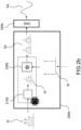
- the figure 2f displays a sixth example of a device in an embodiment of the invention.
- the device 200f receives as input an input digital signal Si, and comprises a digital circuitry 230f to perform a convolution of the input digital signal Si with a second digital signal St' representative of a transform, in order to obtain an output digital signal So, which is supplied to a processing unit 220f, which is a DAC in this example, in order to obtain an analog output signal Sa.
- the second digital signal St' is remarkable in that a value of a second sample of the second digital signal being an approximation of a value of a first sample of a first transform digital signal St, said approximation having a second number of significant bits k 2 lower than or equal to a first number of significant bits k 1 of the value of the first sample. That is to say, the second digital signal is a precalculated approximation of a first digital signal representative of the transform.
- the number of significant bits of the second digital signal St' can thus be defined in order to optimize the perception by users of the quality of the output digital and analog signals. This embodiment is in particular suitable when a pre-defined transform or sample is to be applied to an input signal.
- the second number of significant bits k 2 is lower than or equal to a number of significant bits allowing the output digital signal to match an expected bit depth of a processing unit 220f said output digital signal. It shall be noted that the invention is not restricted to this example, and, in other embodiments of the invention, the output digital signal is not supplied directly to a processing unit, but further transformed. In an aspect of the disclosure, the second number of significant bits k 2 is lower than or equal to a number of significant bits allowing a signal derived from the output digital signal to match an expected bit depth of a processing unit 220f.
- the second number of significant bits k 2 depends at least on the value of the first sample.
- the second number k 2 of significant bits is higher than or equal to a minimum number of significant bits k min of the value of the second sample that does not introduce a noticeable alteration in the output digital signal, or a signal derived therefrom.
- the figures 2a to 2f demonstrate that the disclosure may be implemented in a number of different manners, and that the number of significant bits of samples of digital signals can be reduced in a number of different ways. As already noted, this allows improving the quality perceived by users when the digital signals are processed by a number of different processing units.
- the digital signals may be of different types, for example image, audio or video digital signals.
- any of the input, output or transform digital signals described here may be received from / supplied to other digital circuitries, filters of processing units, such as for example a FIR filter, an IIR (Infinite Impulse Response) filter, a DSP (Digital Signal Processing) unit, etc...
- filters of processing units such as for example a FIR filter, an IIR (Infinite Impulse Response) filter, a DSP (Digital Signal Processing) unit, etc...
- a plurality of different digital circuitries when displayed in a figure, they may represent either a plurality of physically distinct digital circuitries (for example, a plurality of processors), or a plurality of configuration of one or more digital circuitries (for example, a single processor executing a plurality of different sets of code instructions in order to perform a plurality of functions).
- the second digital sample of the second digital signal will be an approximation of the first digital sample of the first digital signal using a second number of significant bits k 2 , lower than or equal to the first number of significant bits of the value of the first sample.
- An approximation of a first digital signal may be obtained by performing a truncation. This operation consists in removing the least significant bits of each sample of the first digital signal. For example, if the first digital signal has a bit depth of 24 bits, and a second digital signal is a truncation of the first digital signal using a bit depth of 16 bits, the value of each sample of the second digital signal will comprise the 16 most significant bits of the value of the corresponding sample of the first digital signal.
- the truncation with Bias may present the disadvantage that the quantization noise is correlated with the first digital signal. This can be avoided by adding a random noise to the signal A before the truncation. This random noise is called "Dither". Different type of dithering can be used, but it is generally assumed that the theoretically optimal Dither is a Dither having a triangular probability density function (TPDF) and an amplitude of +/- E, wherein E is the quantization step introduced by the truncation.
- TPDF triangular probability density function
- D is a random signal (that may have ideally a triangular probability density function, and an amplitude span of +/- E).
- the allocation of the number of significant bits of the second sample may depend at least on the value of the first sample.
- the number of significant bits can be tailored to more optimal values that both improve as much as possible the perception by users of the second digital signal, or a signal derived therefrom, and preserve information from the first sample depending at least on its value.
- the second number of significant bits k 2 is equal to the minimum of a first predefined number Q 1 minus a binary logarithm of the absolute value of the first sample, and a second predefined number Q 2 .
- a rounding operation (for example round to the closer integer, round or floor) may be performed, either on the output of the binary logarithm, or the number k 2 .
- the second number of significant bits k 2 will be comprised between 10 and 16, depending upon the absolute value of the first sample rounded up to the next power of 2 noted as v 1 :
- the "+1" within the log is used for signed integers, to take into account the sign bit.
- the examples above can thus be generalized to values that are not power of twos, and for negative values:
- the second number of significant bits k 2 allows preserving an amount of information from the first sample, which is roughly proportional to the amount of information comprised within the first sample, while ensuring that a minimum number of bits is kept whatever the value of the first sample.
- This embodiment is very well suited for audio digital signals. Indeed, the amount of information detected by a human ear from an audio signal has a logarithmic shape, and this allocation allows adding a bit of information every slice of 6 dB of attenuation. The user thus perceives the amount of information contained by the audio signal as fairly constant over time and over the whole range of possible sample amplitudes.
- This allocation also advantageously allows preserving a constant perceived precision on a wide amplitude of the signal.
- the human brain will perceive a signal which is approximated using the level allocation as a high quality and the user will perceive a very pleasant signal.
- the level allocation can also be defined in the following way:
- the third predefined number Q, fourth predefined number D, and fifth predefined number S are thus parameters defining a level allocation.
- Such a level allocation will be referred as Lev D_L_S on Q bits, or Lev D_L_S on Q bits in K bits.
- some of these parameters can be replaced by a "x" to define a family of level allocation.
- the number of significant bits k 2 of a second sample is then obtained, from the value x(i) of the first sample, by:
- the value of the second sample is then obtained for example by performing a truncation of the value of the first sample on k 2 bits, with or without bias and/or dither.
- the second number of significant bits is defined according to a predicted absolute value of the difference between the value of the first digital sample and an approximation of the first digital sample using a third number of significant bits k 3 , so that the second number of significant bits varies in the same direction than a direction of variation of said absolute value of the difference.
- This type of allocation will be called "Dyn delta allocation”.
- the second number of significant bits, that will be actually used to approximate the first sample is defined according to the absolute value of the difference between the preliminary approximation and the value of the first sample: the higher the absolute value of the difference is (i.e. the more information is lost when a sample is approximated), the higher the number of significant bits k 2 will be (i.e. the more information will be preserved).
- the second number of significant bits k 2 is defined as a growing function of said predicted absolute value of the difference divided by the absolute value of the first sample.
- Allocation Relative Dyn Delta can be performed as defined below.
- the bit depth of the first digital signal is K.
- a preliminary approximation q(i) of the value of said first sample on Q bits is calculated, for example by performing a truncation, or a truncation with bias of the value x(i) of the first sample. Then a relative difference v(i) between the first sample and the preliminary approximation is calculated:
- the relative difference v(i) is thus the absolute value of the difference between the value of the first sample and its approximation on Q bits, and therefore represents the relative loss of information generated by a truncation using Q bits.
- the relative difference v(i) is always comprised between 0 and 1.
- the number of significant bits k 2 is a growing function of the relative difference v(i), that is to say a growing function of the absolute value of the predicted difference (x(i) - q(i)) divided by the value of the first sample. This allows allocating more bits to samples that are more subject to loss of information during the approximation.
- the number of significant bits k 2 of the approximation of a first sample is comprised between Q and Q + D, and is defined according to the relative difference v(i) defined above, using the following rule:
- a Relative Dyn delta allocation calculated using the rules above will be designated DynDeltaRel Q_L_ D on K bits.
- DynDeltaRel Q_L_ D K bits.
- DynDeltaRel 8_L_4 an allocation
- some parameters can be replaced by a "x" to define families of allocations.
- the number of significant bits k 2 of the approximation of a first sample is comprised between Q and Q + D, and is defined according to the absolute difference v(i) defined above using the following rule:
- This example is provided by means of example only of an allocation that depends upon a predicted difference between the value of the first sample, and a preliminary approximation thereof.
- other rules of determination of the second number of significant bits k 2 as a growing function of a difference of the value of the first sample and a preliminary approximation for example as a growing function of w(i).
- This type of allocation of the number of significant bits will be referred to as a "Frequency allocation”. It allows a determination of the number of significant bits k 2 for all samples within a time window, depending upon the values of frequency coefficients. For example, if the first digital signal is an audio signal, the number of significant bits k 2 may be higher if the time window comprises most of its energy in a frequency band that the ear is very sensitive to (for example between 300 Hz and 5 kHz). Therefore, the number of significant bits of the samples of the second digital signal is generally decreased, but more bits of information will be preserved for time windows that the ear is very sensitive to.
- the time windows may be of different sizes, for example 256, 512 or 1024 samples, and the frequency domain transforms that are used to obtain frequency coefficients of different types (for example, a Fourier Transform, DCT (Discrete Cosine Transform), MDCT (Modified Discrete Cosine Transform), etc...
- the time windows may be either overlapping or not overlapping.
- the second number of significant bits k 2 is defined according to a value representative of a derivative of the first digital signal at the first sample.
- the second number of significant bits k 2 may be a decreasing function of the value representative of the derivative of the first digital signal at the first sample: the higher the derivative's absolute value is, the lower the second number of significant bits k 2 can be.
- the derivative may be a first, second, third derivative, etc... or a combination thereof.
- the second number of significant bits k 2 may be a decreasing function of the absolute value of the derivative should be taken into account, in order to ensure that a higher number of bits is used for low variation, whatever their sign.
- the number of significant bits k 2 will be higher for samples wherein a low variation of the first digital signal is observed, and lower for samples wherein a high variation of the first digital signal is observed.
- the number of significant bits can be reduced while preserving information from samples of low variation. This allocation is for example well suited for audio digital signals, for which low variations may be critical.
- high values of a digital signal associated with low variations can be representative of a signal of high amplitude and low frequency or associated to a signal of low amplitude and high frequency.
- the slope allocation allows an important reduction of the number of significant bits, which however preserves the information from the signal of low amplitude and high frequency. If the digital signal is an audio digital signal, this allows preserving meaningful details from the audio signal.
- may be used in a number of embodiments of the invention.
- a level allocation can be performed on the absolute difference
- a dyn delta allocation may also be used, in order to avoid an important distortion of the derivative of the first digital signal.
- An allocation SlopeHigh would preserve more information from high frequency components of a signal, while an allocation SlopeLow would preserve more information from low frequency components of a signal.
- SlopeHigh or SlopeLow allocations may thus be advantageously used depending on target applications, and/or on the components of a signal that shall be preserved in priority. For example, in a two ways active loudspeaker wherein the filter to split the ways is a digital filter, a SlopeLow allocation may be used in the "low-pass" branch, while a SlopeHigh allocation may be used in the "high-pass” branch.
- Each of the allocations described above provides a powerful tool for performing an approximation of values of samples of a first digital signal, according to different objectives. However, they do not allow a complete tailoring of the allocation of the number of significant bits.
- the value of the second sample is selected as a suitable value which is the closest to the value of the first sample in an ordered set of suitable values, and wherein the number of significant bits of each suitable value in the ordered set of suitable values is lower than the number of significant bits of any value in an open interval between said suitable value in the ordered set and an neighbor suitable value in said set.
- the ordered set of values may be completely tailored, for example depending to a desired precision. It can be tailored for different intervals. For example, in an interval wherein a plurality of values that require a low number of bits are already present, a value that requires a high or average number of bits can be removed.
- each value of a first sample is approximated by selecting a neighbor value in a set of suitable values that has a lower number of significant bits.
- the values in the interval [4; 8] are, in a binary notation:
- the values 4 and 8 only belong to the set of suitable values: each value in the interval ]4; 8[ is thus approximated to the closest value, 4 or 8.
- the value 6 also belongs to the set of suitable values. Therefore, this allows approximating the values of the samples of the first digital signal as nearby values that have a lowest number of significant bits, while allowing a complete freedom in the selection of the suitable values.
- the number of significant bits of each suitable value in the ordered set of suitable values has to be lower than the number of significant bits of any value in an open interval between said suitable value in the ordered set and an neighbor suitable value in said set.
- the number of significant bits of the approximated value will always be reduced.
- the ordered set can be obtained for example by first calculating a set of the values that are allowable using one of the previously defined allocation (i.e. any of the allocations previously defined allows a limited set of values), then adding values to or removing values from the set.
- a plurality of allocation means of the second number of significant bits have already been presented.
- Each of the allocations presented, or other allocations that may be envisioned by a skilled man, has its own advantages. However, it may be desirable to combine the advantages of each allocation.
- the allocations may be combined. According to various embodiments of the inventions, the allocations can be combined in different ways.
- an intermediary value can be obtained by approximating the value of a first sample of the first digital signal using a first allocation on an intermediary number of significant bits ki, then this intermediary value can be approximated using a second allocation.
- the first sample may be first truncated, then the truncated value may be approximated using a level allocation.
- Another option for combining the allocations is to obtain two or more candidate number of significant bits using two or more different allocations, then selecting the most appropriate number of significant bits. For example, the higher number of significant bits among the candidates may be selected, in order to ensure that no significant degradation or loss of information is generated.
- two candidates number of significant bits can be obtained, respectively using a level allocation, and a SlopeHigh allocation, then the higher of the two values may be selected. This ensures that the approximation of the samples of the first digital signal preserves information from the first digital signal according to the minimum required number of significant bits criteria defined by the two allocations.
- more than two candidate numbers of bits may be obtained using more than two allocations.
- a person skilled in the art may thus, without effort, combine the best suited allocations in order to ensure that the approximation of the first digital signal does not introduce a noticeable alteration of the signals.
- An allocation may also be determined on a time window, depending on a plurality of candidate allocations on each sample. For example, a second number of significant bits k 2 may be calculated for each sample in the time windows using any of the allocations described above, and a single second number of significant bits k 2 selected to be applied for the approximation of all samples within the time window. For example, the minimum or maximum candidate may be used, or the mean of the candidates. This allows both taking into account the characteristics of a time window and provide a consistent approximation within a time window.
- Figures 3a , 3b and 3c display examples of a device to set the volume of a digital signal in a number of embodiments of the invention.
- Figure 3a displays a first example of a device to set the volume of a digital audio signal in a number of embodiments of the invention.
- the device 300a is configured to change the volume of an input digital audio signal Si, and send the resulting signal to loudspeakers 321a in order to play it.
- the device 300a may be any device that is able to change the volume of a digital audio signal, and send it to loudspeakers.
- the device 300a may be a smartphone, a tablet, a MP3 player, a computer, etc... An end-user or many people may be present in the neighborhood or remotely.
- the device 300a comprises an input unit 340a to let the user set the volume.
- the input unit 340a is represented by a rotative button in the figure 340a, it may take any suitable form, such as a pair of buttons to increase/decrease the volume, a bar on a tactile screen wherein the user can select the desired volume, or an input port to receive a volume level from an external device such as a remote control.
- a transform signal St is defined according to the volume set.
- the transform signal St comprises a single sample, that is representative of the change of volume to apply.
- the change of volume may be either an attenuation or an increase of the volume of the input digital audio signal.
- the device 300a further comprise a digital circuitry 330a to perform a convolution of the input digital audio signal Si and the transform signal St, in order to obtain a first output signal So, which corresponds to the input signal Si to which the volume change set by the user is applied.
- the device 300a further comprises a DAC 320a used to convert an output signal into an analog signal Sa to be sent to the loudspeakers 321a.
- the device 300a also comprises a digital circuitry 310a, which is similar to the digital circuitry 210c of figure 2c : the digital circuitry 210c approximates the first output signal So into a second output signal So' which is supplied to the DAC 320a. More specifically, the digital circuitry310a is configured to calculate the value of a second sample of the second digital signal So' as an approximation of a first sample of the first digital signal using a second bit depth k 2 which is lower than the first bit depth k 1 of the value of the first sample.
- the second number of significant bits k 2 is lower than or equal to the expected bit depth of the DAC 320a. For example, if the first sample has a number of significant bits equal to 24, and the DAC 320a expects 24 bits as input, the digital circuitry 310a can be configured to approximate the first sample using less than 24 bits.
- the second number of significant bits k 2 depends at least on the value of the first sample.
- any of the allocation discussed above can be applied by the digital circuitry 310a.
- the device 300a thus improves the perception by the user of the quality of the output audio signal.
- the approximation performed by the digital circuitry 320a is dependent upon the coefficient of amplitude change that is applied. For example, as will be explained in more details with reference to the figure 2b , due to the attenuation of the signal by a convolution with the signal St, the number of significant bits of the samples of the first output digital signal So is higher than the number of significant bits of the corresponding samples of the input digital signal Si, but the coefficients of amplitude change can be selected in order to control the extra number of significant bits required at the output of the amplitude change.
- the values of amplitude change may be obtained by a level allocation 4_L_1 in 8 bits.
- the digital circuitry 310a is configured to approximate the samples of the first output digital signal So according to the number of significant bits of the sample of the transform signal St:
- the device 300a is provided by means of example only, and some elements may be placed differently.
- the DAC 320a is represented within the device 300a, it may be an external DAC in connection with the device 300a, and the output digital signal So' may be sent to the DAC through the connection.
- the loudspeakers 321a which are represented outside the device 300a in figure 3a , may be internal or integrated loudspeakers. They may also be associated via a contactless network (e.g Bluetooth TM , Zigbee TM , Wi-Fi TM or the like); Loudspeakers can also be headsets, earphones, or the like.
- the second output digital signal is not sent to a DAC and loudspeakers to be listened to, but sent to a further device, or processed, for example compressed.
- the volume control of figure 1 can also be applied to digital audio signals that are not PCM signals.
- it can be applied to DSD (Direct Stream Digital) signals: the DSD signals can be demodulated, then the volume control applied, then the output signal re-modulated into an output DSD signal.
- DSD Direct Stream Digital
- the figure 3b displays a first example of a device to set the volume of a digital audio signal in a number of embodiments of the invention.
- the device 300b is similar in many ways to the device 300a. Indeed, the device 300b also receives an input digital signal Si, comprises an input unit 340b to set a volume change, a transform signal St comprising a single sample representing the volume change is determined accordingly, the device 300b comprises a digital circuitry 330b to perform a convolution of the input digital signal Si with the transform signal St in order to obtain an output digital signal So, which is supplied to a DAC 320b in order to be converted into an analog signal Sa played by loudspeakers 321b. All the embodiments discussed with reference to the device 300a are respectively applicable to the device 300b.
- the device 300b is remarkable in that, instead of performing an approximation of the output digital signal, the transform signal St is approximated, in order that the number of significant bits of the single sample is reduced. Therefore, when the input digital signal Si and the transform signal St are convolved, the number of significant bits of the output digital signal So is reduced compared to the direct application of St.
- the input unit provides values of change of amplitude that require a relatively low number of significant bits to be expressed.
- an amplitude change around -9 dB can be obtained by an amplitude change of -9,28dB, that corresponds to a multiplication of the input digital audio signal by 11/2 5 .
- each sample of the output digital signal will have 5 significant bits in addition of the number of significant bits of the corresponding sample of the input digital signal.
- This is a relatively low number of extra bits by means of example, a more exact approximation of the amplitude change -9dB would be an attenuation of -8,98dB corresponding to a multiplication by 91/2 8 that requires 8 extra bits. Therefore, the invention allows a selection of coefficients of amplitude change that require a lower number of extra bits, thereby improving the user perception of the quality of the output signal.
- the set of suitable coefficients of amplitude change may be dependent upon the required precision of amplitude change.
- the European application n° 17306401.5 filed by the same applicant, and incorporated herein by reference, provides an extended number of examples of selection of the suitable coefficients of amplitude change.
- suitable values of amplitude change can be defined as explained below.
- a set of suitable values such as the set displayed in table 1 next page can be defined by setting the suitable values as defined below:
- the set of suitable values defines a full range of suitable values.
- Each line represents a suitable value, and the columns have the meaning below:
- a set of suitable values of amplitude change can be obtained by the allocations defined in the previous section.
- a level allocation can be used.
- the level allocation advantageously provides a constant precision per slice of 6 dB of attenuation.
- the table 1 above is obtained by a level allocation 4_L_1 on 8 bits, wherein:
- the possible values of the attenuation may also be defined according to Suitable values allocation.
- Suitable values allocation For example, in the table 1, in each slice the value in the form 15/2 k, and the value in the form 13/2 k , which are among the values that require the highest number of significant bits in each slice, can be removed.
- the average step between two possible coefficients of attenuation of the input digital signal becomes 1,34dB, and, in each slice, the suitable values require in average a fewer number of significant bits.
- a level allocation 5_L_1 on 3 bits can be used, and 4 suitable values kept in each slice of 6dB, or a level allocation 3_L_1 on 5 bits can be used, and 16 values kept in each slice of 6 bits. It is also possible to obtain values representative of a greater volume attenuation by using values with a number of significant bits higher than 8, but keep, in each slice of 6 dB of attenuation coefficients, the values that require the lowest number of significant bits.
- the figure 3c displays an example of a device to set the brightness of a digital image signal in a number of embodiments of the invention.
- the device 300c is similar in many ways to the device 300b. Indeed, the device 300c also receives an input digital signal Si (which is in this example an image signal, for example represented by a matrix of RGB, Grayscale or CMYK pixels), comprises an input unit 340c to set a brightness level (in this example, a bar to set a brightness level displayed on the screen; the user sets the brightness by clicking on the right place of the bar using a mouse 341c), a transform signal St comprising a single sample representing the brightness change is determined accordingly, the device 300c comprises a digital circuitry 330c to perform a convolution of the input digital signal Si with the transform signal St in order to obtain an output digital signal So (in this example, an image signal whose brightness has been changed), which is supplied to a video card 320c, in order to be displayed by a screen 321c.
- an input digital signal Si which is in this example an image signal, for example represented by a matrix of RGB, Grayscale or CMYK pixels
- the device 300c comprises a digital
- the device 300c is advantageously remarkable in that, the transform signal St is approximated, in order that the number of significant bits of the single sample is reduced. Therefore, when the input digital signal Si and the transform signal St are convolved, the number of significant bits of the output digital signal So is reduced compared to the direct application of St. Any of the embodiments discussed above for reducing the number of significant bits of the single sample of St can be used. A level allocation, or the use of suitable values are for example well suited here.
- this is advantageously very beneficial for image quality.
- this limits the number of significant bits of the output signal So, while preserving information from the input signal Si. Therefore, this avoid losing information is all information from the signal So is not properly managed by the video card 320c. For example, this allows avoiding erasing information, especially from low luminosity pixel (dark areas of the image), which are very sensitive to loss of information.
- the device 3c thus allows a better rendering of images whose luminosity is modified. This applies as well as an adjustment of the brightness of the whole screen, that the adjustment of the brightness of a single image, for example within an image editing application. This also improves image quality for other kinds of image processing, for example when the image is subsequently stored or compressed, instead of being directly displayed on a screen.
- figure 3c shows a personal computer
- the invention can be implemented within any device that is able to modify the brightness of an image.
- this can be applied to the modification/adaptation of the brightness of a smartphone, connected glasses, TV, any screen (associated and or embedded in automotive devices, planes, remote control, computer or the like) or a tablet.
- the same principle may also be applied to other kinds of image processing.
- a different coefficient of change of amplitude is applied to each pixel of the image, depending on its initial intensity.
- the invention thus allows an improvement the rendering of an image upon a change of the contrast, by using for each coefficient of change of intensity, an approximated value that requires a lowered number of significant bits.
- the figure 3c provides an example of device similar of application of the invention to image signals. More specifically, the device 300b performs operations very similar to the operations of the device 300b, for digital image signals. This example demonstrates that, although most of the examples presented in this application relate to audio signals, the embodiments described can also be applied with similar advantages to other kind of digital signals such as image digital signals.
- Figure 4 displays an example of a device to perform filtering according to the invention.
- the device 400 receives an input digital signal Si, and comprises a digital circuitry 430 to perform a convolution with a second digital signal St' that represents the impulse response of a filter to apply to the input digital signal Si, in order to obtain an output digital signal.
- the output digital signal may thus be sent to a further device, or a processing unit 420 (which may be for example any of the processing units discussed previously: a DAC, a compression unit, etc... or more generally any unit suitable to process a digital signal) within or outside the device 400.
- the device 400 is remarkable in that the second transform signal St' is an approximation of a first transform signal St.
- the second transform signal St' is pre-calculated: for example, in an embodiment of the invention, the input digital signal and the output digital signal are audio signal, and the second transform digital signal is an impulse response a RIAA filter.
- the second transform digital signal St' has been calculated once from a first digital signal St representative of the impulse response of the RIAA filter.
- the digital transform signal St may be representative of the impulse response of different FIR filter, such as a low pass, high pass band pass, RIAA, equalization of phase filter.
- the second transform digital signal St' varies over time.
- the device 400 comprises a digital circuitry 410 to calculate the values of samples of the second transform digital signal St', that approximate values of samples of a first transform digital signal St that varies over time: it is updated in real time, and the digital circuitry 410 calculates the second transform digital signal St' as an approximation of the first transform digital signal St in real time accordingly.
- filters that vary with an environment of the user such as ANC filter that are updated depending on the ambient noise, or spatialization filters that are updated depending on the orientation of the head of a user.
- At least a second sample of the second digital transform digital signal St' is an approximation of at least a first sample of the first digital transform signal St, using a second number of significant bits k 2 lower than a first number of significant bits k 1 of said first sample.
- the second number of significant bits k 2 depends at least on the value of the first sample.
- the device 400 thus allows to reduce the number of significant bits of samples of the output digital signal So, and therefore improve the perception of the quality of the output digital signal So, without losing information from the input digital signal Si.
- the second number k 2 of significant bits is higher than or equal to a minimum number of significant bits k min of the value of the second sample that does not introduce a noticeable alteration in the second output digital signal.
- the alteration may be an alteration of the functionality of a FIR filter where the second digital transform signal St' is an impulse response.
- the second digital transform signal St' is an impulse response of a low pass filter
- an excessive reduction of the number of significant bits may lead to the transform signal not performing accurately the low pass filtering, the cutoff frequency of the filter be displaced or the stop-band attenuation is not strong enough, etc...
- the alteration may also be specific alterations such as aliasing.
- the device 400 may also comprise, in addition, a digital circuitry to perform an approximation of the output digital signal So, in order to further reduce the number of significant bits of the samples of the output digital signal.
- Figures 5a, 5b and 5c display, respectively, the frequency response of a prior art lowpass filter whose coefficients are quantized using 16 bits, the frequency response of a lowpass filter of the invention, and the impulse response of a lowpass filter of the invention.
- the curve 500a represents the frequency response of a 200 Hz low pass filter of the prior art quantized using 16 bits, as a power depending on the frequency.
- the curve 500b represents the frequency response of a corresponding low pass filter of the invention.
- the curve 500c represents an impulse response of the same low pass filter of the invention, as an amplitude as function of time. More specifically, the low pass filter of the invention is obtained by performing an approximation of the impulse response of the filter displayed in figure 5a . At least a sample of the approximation has a second number of significant bits k 2 lower than a first number of significant bits k 1 of the corresponding sample of the impulse response of the filter 500a. In the example of figures 5a to 5c , the number of significant bits k 2 is determined according to a truncation combined with a level allocation 4_L_1 on 8 bits.
- Figures 6a, 6b and 6c display respectively the frequency responses of a prior art RIAA filter whose coefficients are quantized using 16 bits, the frequency response of a RIAA filter of the disclosure, and the impulse response of a RIAA filter of the invention.
- the curve 700 represents the frequency response of a RIAA filter of the prior art quantized using 16 bits, as magnitude vs frequency.
- the curve 600b represents the frequency response of a corresponding RIAA filter of the invention, that is to say a RIAA filter whose coefficients are an approximation of the coefficients of the filter 700 according to the invention.
- the curve 600c represents an impulse response of the same RIAA filter of the disclosure, as an amplitude as function of time.
- a slope allocation has been used to perform the approximation: different numbers of significant bits have been used, in the filter of the disclosure, for different samples. More specifically, a higher number of bits of precision have been used for the samples that have a steep variation from one sample to another. It can thus be seen 610c that, when the variation between successive samples decreases, the number of bits of precision used to represent the samples is also reduced, in order to prevent losses of information.
- Figure 7 displays an example of a device allowing to perform an upsampling of a digital signal in a number of embodiments of the invention.
- the device 700 is portable music player.
- the portable device comprises a memory to store compressed music files, for example a MP3 file 741.
- the device 700 comprises a decompression unit 740 to decompress the MP3 file 741 into an input audio digital signal Si.
- the device 700 is configured to upsample the input digital audio signal Si to an output sampling rate that is a multiple of its sampling rate.
- the input audio digital signal Si can be a 16 bits/44,1 Hz audio signal (CD format)
- the device 700 can be configured to upsample the input audio digital signal into a first output digital signal So at 24 bits/88,2 kHz, or at a sampling rate of 176, 4 kHz or 352, 8 kHz.
- the sampling rate is thus multiplied by a factor of 2, 4 or 8 respectively.
- the device 720 comprises a DAC 720 to convert an output digital audio signal to an output analog audio signal Sa to be sent to earphones 721.
- the device 700 comprises a digital circuitry 742 configured to create an upsampled input digital signal Si up at the output sampling rate.
- the upsampled input digital signal Si up comprises the samples of the input digital signal Si spaced apart by null samples, according to the upsampling ratio.
- the upsampled input digital signal Si up will comprise the first sample of the input digital signal, a sample with a null value, the second sample of the input digital signal, a sample with a null value, the third sample of the input digital signal, etc...
- the samples of upsampled input digital signal Si up that have a value of the input digital signal Si are called "Phase 0", while the null samples are called "Phase 1".
- the upsampled input digital signal Si up will comprise the first sample of the input digital signal, three samples with null values, the second sample of the input digital signal, three samples with null values, the third sample of the input digital signal, etc...
- the samples of upsampled input digital signal Si up that have a value of the input digital signal Si are still called “Phase 0", while the three intermediary null samples are called respectively "Phase 1", “Phase 2", “Phase 3".
- the same principle is applicable to higher upsamplings. For example, if the input digital signal Si is upsampled from 44,1 kHz to 352,8 kHz (x8 upsampling), the "Phase 0" samples of the upsampled input digital Si up are spaced apart by 7 samples.
- the device 700 further comprises a digital circuitry 730 to perform a convolution of the upsampled input digital Si up with a lowpass transform digital signal St to obtain a first output audio digital signal So, which is an upsampled version of the input audio digital signal Si.
- the cutoff frequency of the lowpass transform digital filter is usually about at half of the sampling frequency of the input audio digital signal, for example about 20 kHz if the input audio digital signal is sampled at 44,1 kHz.
- the lowpass filter does not modify the samples that were initially present in the input audio digital signal Si ("Phase 0" samples).
- the other samples (“Phase 1", “Phase 2", “Phase 3", etc... samples) are upsampled samples.
- the low-pass filter can for instance be implemented based on an impulse response derived from a spline function.
- a Spline function based on 11 points (11 th order spline) is for example well suited to perform upsampling.
- the lowpass transform digital signal St may have different bit depths.
- Typical bit depth for such filter is 24 or 32 bits. Therefore, when the input audio digital signal is a 16 bits signal, the first output digital signal has a bit depth of 40 or 48 bits, and thus far exceeds the input bit depth of most DACs. The same situation occurs for virtually any audio bit depth. For example, the bit depth of the first output audio signal So will be even higher if the input audio digital signal has a bit depth of more than 16 bits.
- the device 700 is configured to reduce the number of significant bits of the output digital signal sent to the DAC 720.
- the number of significant bits of the samples of the transform digital signal can be reduced, for example by performing a truncation of the digital transform signal St, for example on 16 bits.
- the first output audio digital signal So is sent directly to the DAC 720 to be converted and listened to.
- the device 700 comprises a digital circuitry 710, for example similar to the digital circuitry 210c, to obtain a second output audio digital signal So' as an approximation of the first output digital signal So using a lower number of significant bits.
- the second output audio digital signal So' is sent to the DAC 720 instead of the first output digital signal So.
- the digital circuitry 710 can perform truncations of the samples of first output digital signal So, or use a level allocation.
- the same operations can be applied to all samples of the output digital signal, or the phases of the output digital signal may be processed differently.
- the samples corresponding to the Phase 0 are not approximated, or are approximated using a higher number of significant bits than the samples corresponding to the other phases. Indeed, since the Phase 0 samples are values of samples of the input audio digital signal that are not modified, their values can be advantageously preserved, while the number of significant bits of the values of the other phases are reduced.
- this embodiment provides a very high sound quality. Indeed, the truncation of the transform signal on 16 bits allows a good enough representation of the upsampling filter, while the level allocation is well suited to approximate audio samples.
- the device 700 is provided by means of non-limitative example only of a device to perform an upsampling of a digital signal in a number of embodiments of the invention, but the invention is not restricted to this example.
- a device to perform an upsampling of a digital signal in a number of embodiments of the invention, but the invention is not restricted to this example.
- the upsampling as used by the device 700 greatly increases the perception by users of the quality of the sound.
- the inventors have noticed that the perception of the sound quality is even increased, when the input audio digital signal is obtained by decompressing a compressed audio file, and more specifically a file encoded in MP3 format.
- the perception of sound quality when listening a MP3 file using the device 700 is thus advantageously greatly optimized, compared to a prior art listening of a MP3 files.
- Figures 8a and 8b display examples of devices and systems for processing of audio signals according to a number of embodiments of the invention.
- Figure 8a displays an example of a device to listen to audio file according to a number of embodiments of the invention.
- the device 800a is a portable audio player, and is configured to obtain an input audio digital signal Si, for example directly from a raw audio file 842a (for example a 16 bits or 24 bits WAV file, an audio CD or HD audio), or a compressed audio file 841a (for example a MP3 file), the audio file being decompressed by a decompression unit 840a.
- a raw audio file 842a for example a 16 bits or 24 bits WAV file, an audio CD or HD audio
- a compressed audio file 841a for example a MP3 file
- the device 800a comprises a digital circuitry 810a to approximate the input digital audio signal into an output digital audio signal So, which is similar to the digital circuitry 210a.
- the output digital signal So is supplied to a DAC 820a to be converted into an analog output signal Sa and listened to through earphones 821a.
- the device 800a is provided by means of example only, and a number of other devices of the invention allow an approximation of a raw or compressed digital audio signal.
- the sound may be listened to using loudspeakers, the device may be a laptop, or the input digital audio signal Si may be a streamed signal instead of a signal stored within a file.
- At least a second sample of the output digital audio signal So has a second number of significant bits k 2 lower than a first number of significant bits k 1 of a corresponding value of a first sample of the input digital audio signal Si.
- the second number of significant bits k 2 is lower than or equal to the expected bit depth of the DAC 820a.
- the second number of significant bits k 2 depends upon the value of the first sample.
- the digital circuitry 810a can advantageously use a truncation with bias or a level allocation with bias to approximate the values of the samples.
- the samples of the output digital signal will thus have a maximum bit depth of 16 bits, even if the output digital signal has a higher bit depth, for example 24 bits.
- the device 800a also provides a significant improvement when listening to a compressed file.
- the device 800a also provide the advantage of being applicable to virtually any hardware, while the improvement of quality of the compressed audio signal of device 700, which relies on an upsampling of the output signal, may not be applicable if an upsampled signal cannot be processed afterwards (this is in particular the case if audio streams cannot be played at high bitrates, for examples in some smartphones, or using some Bluetooth TM loudspeakers).
- the digital circuitry 810a is integrated within an application of a smartphone, for example a music streaming application. It thus allows the music application to provide an improved sound quality to the user, while not requiring any modification of the hardware, and without requiring an increase of the bitrate of a compressed audio stream received by the smartphone.
- the figure 8b displays an audio streaming system in a number of embodiments of the invention.
- the audio streaming system 800b comprises a server 801b to compress an audio file, and a listening device 802b to listen to the compressed audio file.
- the server 801b receives an uncompressed audio file 840b, for example a music track that comprises a first input digital audio signal Si.
- the server 801b comprises a digital circuitry 810b to approximate values of the samples of the first input audio digital signal Si in order to obtain a second input digital audio signal Si' and which is similar to the digital circuitry 210a.
- the server 801b further comprises a compressor 820b, in order to compress the second output digital signal Si' into a compressed file 821b, for example a MP3 file.
- the MP3 file is streamed to a user device 802b.
- the device is a laptop.
- the invention is not restricted to this example, and other user devices may be used, provided that they have the capability to receive compressed audio streams, decompress such streams, and play the decompressed audio signal.
- the device 802b has a MP3 decoder 841b, to decompress the MP3 file into a first decompressed audio stream Sd.
- the first decompressed audio stream Sd may be either fed directly to a DAC 822b, or further processed by a digital circuitry 811b, similar to the digital circuitry 210a, to approximate the first decompressed audio stream Sd into a second decompressed audio stream Sd' which is fed to the DAC 822b.
- the approximation performed by the digital circuitry 811b aims at reducing the number of significant bits of one or more samples of the decompressed audio stream, in order to improve the perception of audio quality by the user.
- the DAC 822b converts the first decompressed audio stream Sd, or the second decompressed audio stream Sd' into a decompressed analog audio stream Sa, which is send via a Bluetooth connection to a Bluetooth TM loudspeaker 823b.
- the reduction of the number of significant bits of the audio signal by the digital circuitries 810b and/or 811b improves the perception of audio quality by the user. Moreover, the reduction of the number of significant bits of the audio signal by the digital circuitry 810b allows compressing the audio stream with a higher bitrate with the same subjective quality. Therefore, this allows saving bandwidth.
- the digital circuitries 810b or 811b can be used separately. The applicant has noted that the application of a level allocation on the digital circuitry 810b and/or 811b provides a very good listening quality.
- the reduction of the number of significant bits by the digital circuitry 811b allows a further improvement of the perceived quality by the user.
- the reduction of the number of significant bits performed by each of the digital circuitries 810b and 811b may be limited to a minimum number of significant bits k min that does not alter the signal, for example by not reducing the number of significant bits of audio sample below 10 bits, the reduction of the number of significant bits can be performed independently by the two digital circuitries.
- a compression algorithm such as the MP3 compresses an audio file in the form of frequency coefficients. Therefore, the samples the decompressed audio signal Sd are not directly derived from the samples of the second input digital signal Si'.
- the system 800b can thus be used for a streaming system, but also a system to sell music online.
- the digital circuitry 811b can be embedded within a music playing application or software.
- the system 800b is provided by means of non limitative example only, and the invention also extends to a number of other systems for streaming and listening audio.
- the invention also extends to a number of other systems for streaming and listening audio. For example:
- a digital circuitry of the invention may be used to reduce the number of significant bits of an audio signal at recording time.
- an audio signal is recorded, for example in an audio studio, the sound is first captured as an analog signal, which is converted into a digital audio signal using an ADC (Analog to Digital Converter).
- ADC Analog to Digital Converter
- a level allocation type x_L_1 with Bias is for example well suited for this application.
- the bit depth and sampling rate are generally much higher than the CD format: the audio signal generally has a bit depth of 24 bits, and a sampling rate of 96 kHz or 192 kHz.
- a digital circuitry of the invention can be used to reduce the number of significant bits of the audio signal at the output of the ADC. For example a level allocation 8_L_1 on 16 bits can be used, the bit depth of the audio file being 24 bits. This allocation allows the audio signals to have a constant precision and a distortion which is constant in a dynamic range of 48dB that allows to preserve the content and meaning of the audio signal.
- the invention is also applicable to the mastering of an audio record.
- the mastering is the final stage of audio recording, wherein an audio track is processed to be adapted to a number of different listening platforms.
- the source of the mastering is the HD recorded audio track, generally at 24 bits, and 96 kHz or 192 kHz).
- the audio track may be converted to different formats, such as HD formats, but also more widespread CD format (16 bits / 44,1 kHz).
- the conversion of the master audio track an audio track in the CD format comprises:
- the invention can be applied to these two steps:
- the reduction of the number of significant bits of an audio signal of the invention can also be used as a pre-processing for virtually any processing of a digital audio signal, such as digital filtering, upsampling, volume change, etc... , using any allocation of bits previously defined, or any allocation of its that may be envisioned by a skilled man according to the invention.
- a different level allocation can be used for the different samples.
- the number of significant bits of successive samples may be defined according to different level allocations according to the index of the sample in a interval.
- a period of 4 samples may be defined, with the following allocations being used:
- variable allocations avoids the creation of a constant, and noticeable sound color in the signal. Thus, the audio signal does not seem artificial.
- This embodiment is not restricted to the example above: for example, different level allocations may be used, other allocations may be used instead of a level allocation (or even a mix of different types of allocations depending on the sample).
- different periods may be used (for example 2, 6 or 8 samples instead of 4. It is even possible to change the allocation type used for each sample based on irregular periods, or choose an allocation randomly for each sample, among a set of possible allocations.
- the disclosure also relates to a method to calculate a value of a second sample of a second digital signal as an approximation of a value of a first sample of a first digital signal, to which any of the embodiments discussed above may be applied.
- the disclosure also relates to the convolution of an input signal with a second digital signal, wherein a second sample of the second digital signal is an approximation of a value of a first sample of a first digital signal, to which any of the embodiments discussed above may be applied.
- the disclosure also relates to a second digital signal, a second sample of the second digital signal being an approximation of a first sample of a first digital signal, to which any of the embodiments discussed above may be applied.
- a sample of the first digital signal to be approximate already has a very low first number of significant bits, lower than a second number of significant bits that is allocated by an allocation of the disclosure. In such case, the approximation may not have any effect, and the values of the first and second sample may be identical.
Landscapes
- Engineering & Computer Science (AREA)
- Theoretical Computer Science (AREA)
- Physics & Mathematics (AREA)
- General Physics & Mathematics (AREA)
- Pure & Applied Mathematics (AREA)
- Computational Mathematics (AREA)
- Mathematical Analysis (AREA)
- Mathematical Optimization (AREA)
- Mathematical Physics (AREA)
- Data Mining & Analysis (AREA)
- General Engineering & Computer Science (AREA)
- Computing Systems (AREA)
- Algebra (AREA)
- Databases & Information Systems (AREA)
- Software Systems (AREA)
- Compression, Expansion, Code Conversion, And Decoders (AREA)
- Analogue/Digital Conversion (AREA)
- Complex Calculations (AREA)
Applications Claiming Priority (3)
| Application Number | Priority Date | Filing Date | Title |
|---|---|---|---|
| EP17306401.5A EP3471271A1 (de) | 2017-10-16 | 2017-10-16 | Verbesserte konvolutionen von digitalen signalen mit verwendung einer bitanforderungsoptimierung eines digitalen zielsignals |
| EP18305011.1A EP3471272A1 (de) | 2017-10-16 | 2018-01-08 | Verbesserte konvolutionen von digitalen signalen unter verwendung einer bitanforderungsoptimierung eines digitalen zielsignals |
| EP18305545.8A EP3471273A1 (de) | 2017-10-16 | 2018-05-02 | Annäherung von abtastwerten eines digitalen signals durch reduktion der anzahl von signifikanten bits entsprechend den werten der abtastwerte |
Related Parent Applications (1)
| Application Number | Title | Priority Date | Filing Date |
|---|---|---|---|
| EP18305545.8A Division EP3471273A1 (de) | 2017-10-16 | 2018-05-02 | Annäherung von abtastwerten eines digitalen signals durch reduktion der anzahl von signifikanten bits entsprechend den werten der abtastwerte |
Publications (2)
| Publication Number | Publication Date |
|---|---|
| EP4518162A2 true EP4518162A2 (de) | 2025-03-05 |
| EP4518162A3 EP4518162A3 (de) | 2025-06-04 |
Family
ID=60262860
Family Applications (5)
| Application Number | Title | Priority Date | Filing Date |
|---|---|---|---|
| EP17306401.5A Withdrawn EP3471271A1 (de) | 2017-10-16 | 2017-10-16 | Verbesserte konvolutionen von digitalen signalen mit verwendung einer bitanforderungsoptimierung eines digitalen zielsignals |
| EP18305011.1A Pending EP3471272A1 (de) | 2017-10-16 | 2018-01-08 | Verbesserte konvolutionen von digitalen signalen unter verwendung einer bitanforderungsoptimierung eines digitalen zielsignals |
| EP18305546.6A Pending EP3471274A1 (de) | 2017-10-16 | 2018-05-02 | Annäherung von proben eines digitalen signals zur reduzierung einer anzahl an signifikanten bits |
| EP25151379.2A Pending EP4518162A3 (de) | 2017-10-16 | 2018-05-02 | Annäherung von abtastwerten eines digitalen signals, die eine anzahl von signifikanten bits entsprechend den werten der abtastwerte reduziert |
| EP18305545.8A Ceased EP3471273A1 (de) | 2017-10-16 | 2018-05-02 | Annäherung von abtastwerten eines digitalen signals durch reduktion der anzahl von signifikanten bits entsprechend den werten der abtastwerte |
Family Applications Before (3)
| Application Number | Title | Priority Date | Filing Date |
|---|---|---|---|
| EP17306401.5A Withdrawn EP3471271A1 (de) | 2017-10-16 | 2017-10-16 | Verbesserte konvolutionen von digitalen signalen mit verwendung einer bitanforderungsoptimierung eines digitalen zielsignals |
| EP18305011.1A Pending EP3471272A1 (de) | 2017-10-16 | 2018-01-08 | Verbesserte konvolutionen von digitalen signalen unter verwendung einer bitanforderungsoptimierung eines digitalen zielsignals |
| EP18305546.6A Pending EP3471274A1 (de) | 2017-10-16 | 2018-05-02 | Annäherung von proben eines digitalen signals zur reduzierung einer anzahl an signifikanten bits |
Family Applications After (1)
| Application Number | Title | Priority Date | Filing Date |
|---|---|---|---|
| EP18305545.8A Ceased EP3471273A1 (de) | 2017-10-16 | 2018-05-02 | Annäherung von abtastwerten eines digitalen signals durch reduktion der anzahl von signifikanten bits entsprechend den werten der abtastwerte |
Country Status (4)
| Country | Link |
|---|---|
| US (3) | US11184022B2 (de) |
| EP (5) | EP3471271A1 (de) |
| CN (3) | CN111602340B (de) |
| WO (3) | WO2019076783A1 (de) |
Families Citing this family (7)
| Publication number | Priority date | Publication date | Assignee | Title |
|---|---|---|---|---|
| US10937436B2 (en) * | 2018-03-31 | 2021-03-02 | Jochem Welvaadt | Method and system for encoding and decoding of audio signals |
| CN114766051A (zh) * | 2019-12-27 | 2022-07-19 | 罗姆股份有限公司 | 音频电路、dsd信号的再现方法 |
| JP7749603B2 (ja) * | 2020-06-22 | 2025-10-06 | ドルビー・インターナショナル・アーベー | 自動マルチトラックミキシングのためのシステム |
| CN112492473B (zh) * | 2020-11-04 | 2022-09-09 | 杭州士兰微电子股份有限公司 | Mems麦克风的信号处理电路及信号处理方法 |
| DE102021207032A1 (de) * | 2021-07-05 | 2023-01-05 | Robert Bosch Gesellschaft mit beschränkter Haftung | SA-Radarsensor für Kraftfahrzeuge |
| CN116257207B (zh) * | 2022-09-08 | 2023-10-03 | 重庆位图信息技术有限公司 | 一种数据截位方法、模块、计算机设备及存储介质 |
| WO2024108379A1 (en) * | 2022-11-22 | 2024-05-30 | Intel Corporation | Method and system of video coding with neural network-based reduced bit-depth input image data |
Family Cites Families (72)
| Publication number | Priority date | Publication date | Assignee | Title |
|---|---|---|---|---|
| US3711650A (en) * | 1970-10-26 | 1973-01-16 | Logicon Inc | Adaptive pulse code modulation system |
| US3993993A (en) * | 1972-06-06 | 1976-11-23 | Rca Corporation | Digital-to-synchro converter |
| US4229800A (en) * | 1978-12-06 | 1980-10-21 | American Microsystems, Inc. | Round off correction logic for modified Booth's algorithm |
| US4412208A (en) * | 1980-09-16 | 1983-10-25 | Nippon Telegraph & Telephone Public Corporation | Digital to analog converter |
| JPS6380626A (ja) * | 1986-09-24 | 1988-04-11 | Yamaha Corp | デイジタル・アナログ変換回路 |
| JP2683705B2 (ja) * | 1988-10-27 | 1997-12-03 | ナカミチ株式会社 | ディジタル/アナログ変換装置 |
| US5230038A (en) * | 1989-01-27 | 1993-07-20 | Fielder Louis D | Low bit rate transform coder, decoder, and encoder/decoder for high-quality audio |
| DE69029706T2 (de) * | 1989-10-31 | 1997-06-05 | Canon Kk | Bilderzeugungsgerät zur Halbtonwiedergabe |
| TW304316B (de) * | 1990-10-03 | 1997-05-01 | Yamaha Corp | |
| DE69233256T2 (de) * | 1991-05-29 | 2004-05-27 | Pacific Microsonics, Inc., Berkeley | Verbesserungen in Codierung-/Decodierungssystemen |
| US5243348A (en) * | 1992-04-27 | 1993-09-07 | Motorola, Inc. | Partitioned digital encoder and method for encoding bit groups in parallel |
| US5353026A (en) * | 1992-12-15 | 1994-10-04 | Analog Devices, Inc. | Fir filter with quantized coefficients and coefficient quantization method |
| US5625358A (en) * | 1993-09-13 | 1997-04-29 | Analog Devices, Inc. | Digital phase-locked loop utilizing a high order sigma-delta modulator |
| US5574454A (en) * | 1993-09-13 | 1996-11-12 | Analog Devices, Inc. | Digital phase-locked loop utilizing a high order sigma-delta modulator |
| DE19535615A1 (de) * | 1994-10-20 | 1996-05-02 | Analogic Corp | Datenerfassungssystem, insbesondere für Computertomographie-Geräte |
| JP3729529B2 (ja) * | 1994-10-28 | 2005-12-21 | ソニー株式会社 | デイジタル信号送受信システム |
| US5587710A (en) * | 1995-03-24 | 1996-12-24 | National Semiconductor Corporation | Syntax based arithmetic coder and decoder |
| US5696710A (en) * | 1995-12-29 | 1997-12-09 | Thomson Consumer Electronics, Inc. | Apparatus for symmetrically reducing N least significant bits of an M-bit digital signal |
| US5748126A (en) * | 1996-03-08 | 1998-05-05 | S3 Incorporated | Sigma-delta digital-to-analog conversion system and process through reconstruction and resampling |
| JPH1084281A (ja) * | 1996-09-06 | 1998-03-31 | Nec Corp | Da変換装置 |
| US5838272A (en) * | 1997-04-17 | 1998-11-17 | President And Fellows Of Harvard College | Error correcting sigma-delta modulation decoding |
| US6147631A (en) * | 1998-12-09 | 2000-11-14 | Cirrus Logic, Inc. | Input sampling structure for delta-sigma modulator |
| AUPP790598A0 (en) * | 1998-12-23 | 1999-01-28 | Lake Dsp Pty Limited | Efficient impulse response convolution method and apparatus |
| US6243729B1 (en) * | 1998-12-31 | 2001-06-05 | Texas Instruments Incorporated | Digital finite-impulse-response (FIR) filter with a modified architecture based on high order Radix-N numbering |
| JP3726574B2 (ja) * | 1999-08-05 | 2005-12-14 | ヤマハ株式会社 | D/a変換装置 |
| US6505221B1 (en) * | 1999-09-20 | 2003-01-07 | Koninklijke Philips Electronics N.V. | FIR filter utilizing programmable shifter |
| US6326912B1 (en) * | 1999-09-24 | 2001-12-04 | Akm Semiconductor, Inc. | Analog-to-digital conversion using a multi-bit analog delta-sigma modulator combined with a one-bit digital delta-sigma modulator |
| SE522440C2 (sv) * | 2000-01-31 | 2004-02-10 | Ericsson Telefon Ab L M | Omvandlare |
| KR20020093818A (ko) * | 2000-02-29 | 2002-12-16 | 제너럴 인스트루먼트 코포레이션 | 개선된 케이블 tv 네트워크 성능을 위한 디지털 처리구조의 응용 |
| GB2366440A (en) * | 2000-09-05 | 2002-03-06 | Sharp Kk | Driving arrangement for active matrix LCDs |
| GB2373975B (en) * | 2001-03-30 | 2005-04-13 | Sony Uk Ltd | Digital audio signal processing |
| US6720899B2 (en) * | 2001-08-07 | 2004-04-13 | Hrl Laboratories, Llc | Extended precision pixel |
| EP1292036B1 (de) * | 2001-08-23 | 2012-08-01 | Nippon Telegraph And Telephone Corporation | Verfahren und Vorrichtung zur Decodierung von digitalen Signalen |
| US7031401B2 (en) * | 2002-02-12 | 2006-04-18 | Broadcom Corporation | Digital to analog converter with time dithering to remove audio tones |
| US6825785B1 (en) * | 2002-02-28 | 2004-11-30 | Silicon Laboratories, Inc. | Digital expander apparatus and method for generating multiple analog control signals particularly useful for controlling a sub-varactor array of a voltage controlled oscillator |
| US6646581B1 (en) * | 2002-02-28 | 2003-11-11 | Silicon Laboratories, Inc. | Digital-to-analog converter circuit incorporating hybrid sigma-delta modulator circuit |
| US7031395B2 (en) * | 2002-03-29 | 2006-04-18 | Northrop Grumman Corporation | Apparatus and methods for digital-to-analog conversion |
| DE10217297A1 (de) * | 2002-04-18 | 2003-11-06 | Fraunhofer Ges Forschung | Vorrichtung und Verfahren zum Codieren eines zeitdiskreten Audiosignals und Vorrichtung und Verfahren zum Decodieren von codierten Audiodaten |
| US7116721B1 (en) * | 2002-05-20 | 2006-10-03 | Cirrus Logic, Inc. | Delta-sigma modulators with integral digital low-pass filtering |
| US7142606B2 (en) * | 2002-09-27 | 2006-11-28 | Freescale Semiconductor, Inc. | Method and apparatus for shared processing a plurality of signals |
| US7986932B1 (en) * | 2002-11-19 | 2011-07-26 | National Semiconductor Corporation | Fixed point FIR filter with adaptive truncation and clipping and wireless mobile station using same |
| US7061312B2 (en) * | 2003-03-21 | 2006-06-13 | D2Audio Corporation | Systems and methods for providing multi channel pulse width modulated audio with staggered outputs |
| EP1622275B1 (de) * | 2003-04-28 | 2018-09-12 | Nippon Telegraph And Telephone Corporation | Digitales signalumkehrbares codierungsverfahren des fliesskommatyps, decodierungsverfahren , einrichtungen dafür und programme dafür |
| US6958717B1 (en) * | 2003-08-25 | 2005-10-25 | Analog Devices, Inc. | Method and apparatus for interconnecting analog and digital sections of A/D and D/A converters |
| US7009533B1 (en) * | 2004-02-13 | 2006-03-07 | Samplify Systems Llc | Adaptive compression and decompression of bandlimited signals |
| EP1691487B1 (de) * | 2005-02-10 | 2009-12-02 | STMicroelectronics S.r.l. | Dynamikbereichsverbesserung eines Multibit-Analog-Digital-Wandlers |
| GB2425416B (en) * | 2005-04-19 | 2009-10-14 | Wolfson Microelectronics Plc | Improved switched capacitor DAC |
| US7199739B2 (en) * | 2005-06-15 | 2007-04-03 | Sigmatel, Inc. | Programmable sample rate analog to digital converter and method for use therewith |
| US7650560B2 (en) * | 2006-03-31 | 2010-01-19 | Panasonic Corporation | Packet transmission apparatus and method using optimized punctured convolution codes |
| US8139112B2 (en) * | 2006-08-07 | 2012-03-20 | Sightlogix, Inc. | Methods and apparatus related to improved surveillance |
| US8126164B2 (en) * | 2006-11-29 | 2012-02-28 | Texas Instruments Incorporated | Digital compensation of analog volume control gain in a digital audio amplifier |
| US8942289B2 (en) * | 2007-02-21 | 2015-01-27 | Microsoft Corporation | Computational complexity and precision control in transform-based digital media codec |
| US8369973B2 (en) * | 2008-06-19 | 2013-02-05 | Texas Instruments Incorporated | Efficient asynchronous sample rate conversion |
| IT1393809B1 (it) * | 2008-10-22 | 2012-05-11 | St Wireless Sa | Unità aritmetico-logica per processore di segnali digitali |
| US8611558B2 (en) * | 2009-02-26 | 2013-12-17 | Adobe Systems Incorporated | System and method for dynamic range extension using interleaved gains |
| US8301803B2 (en) * | 2009-10-23 | 2012-10-30 | Samplify Systems, Inc. | Block floating point compression of signal data |
| US8633370B1 (en) * | 2011-06-04 | 2014-01-21 | PRA Audio Systems, LLC | Circuits to process music digitally with high fidelity |
| WO2013101233A1 (en) * | 2011-12-30 | 2013-07-04 | Intel Corporation | Floating point round-off amount determination processors, methods, systems, and instructions |
| US9467113B2 (en) * | 2012-08-30 | 2016-10-11 | Avatekh, Inc. | Method and apparatus for signal filtering and for improving properties of electronic devices |
| GB2507096B (en) * | 2012-10-19 | 2016-03-23 | Cirrus Logic Int Semiconductor Ltd | Digital/analogue conversion |
| US9697837B2 (en) * | 2012-12-17 | 2017-07-04 | Yaron Hefetz | Secured audio channel for voice communication |
| US9391576B1 (en) * | 2013-09-05 | 2016-07-12 | Cirrus Logic, Inc. | Enhancement of dynamic range of audio signal path |
| EP3116261A4 (de) * | 2014-03-24 | 2017-03-08 | Huawei Technologies Co. Ltd. | Verfahren zur übertragung von pl-daten und datenübertragungsvorrichtung |
| CN103944575A (zh) * | 2014-04-21 | 2014-07-23 | 中国科学院半导体研究所 | 过采样64倍有效位数为18位的σ-δ调制电路 |
| US9788721B2 (en) * | 2014-07-22 | 2017-10-17 | Biobit, Inc. | Low-power activity monitoring |
| KR20160086666A (ko) * | 2015-01-12 | 2016-07-20 | 삼성전기주식회사 | 디지털-아날로그 변환 장치, 그를 이용한 모터 구동 제어 장치 및 방법 |
| ITUB20153503A1 (it) * | 2015-09-09 | 2017-03-09 | St Microelectronics Srl | Procedimento e dispositivo di controllo della dinamica, apparecchiatura e prodotto informatico |
| US10283032B2 (en) * | 2015-10-07 | 2019-05-07 | Samsung Display Co., Ltd. | Integrated circuit for nonlinear data encoding |
| US10448030B2 (en) * | 2015-11-16 | 2019-10-15 | Ostendo Technologies, Inc. | Content adaptive light field compression |
| CN110337636A (zh) * | 2018-02-28 | 2019-10-15 | 深圳市大疆创新科技有限公司 | 数据转换方法和装置 |
| GB201810092D0 (en) | 2018-06-20 | 2018-08-08 | Ctxt Pty Ltd | Compounds |
| KR102214837B1 (ko) * | 2019-01-29 | 2021-02-10 | 주식회사 디퍼아이 | 컨벌루션 신경망 파라미터 최적화 방법, 컨벌루션 신경망 연산방법 및 그 장치 |
-
2017
- 2017-10-16 EP EP17306401.5A patent/EP3471271A1/de not_active Withdrawn
-
2018
- 2018-01-08 EP EP18305011.1A patent/EP3471272A1/de active Pending
- 2018-05-02 EP EP18305546.6A patent/EP3471274A1/de active Pending
- 2018-05-02 EP EP25151379.2A patent/EP4518162A3/de active Pending
- 2018-05-02 EP EP18305545.8A patent/EP3471273A1/de not_active Ceased
- 2018-10-15 WO PCT/EP2018/077992 patent/WO2019076783A1/en not_active Ceased
- 2018-10-15 CN CN201880080979.4A patent/CN111602340B/zh active Active
- 2018-10-15 US US16/756,379 patent/US11184022B2/en active Active
- 2018-10-15 CN CN201880080788.8A patent/CN111527702B/zh active Active
- 2018-10-15 US US16/756,241 patent/US11038524B2/en active Active
- 2018-10-15 US US16/756,295 patent/US11277147B2/en active Active
- 2018-10-15 CN CN201880080789.2A patent/CN111527703B/zh active Active
- 2018-10-15 WO PCT/EP2018/077990 patent/WO2019076781A1/en not_active Ceased
- 2018-10-15 WO PCT/EP2018/077993 patent/WO2019076784A1/en not_active Ceased
Also Published As
| Publication number | Publication date |
|---|---|
| US20210194499A1 (en) | 2021-06-24 |
| CN111527703B (zh) | 2024-02-23 |
| EP3471272A1 (de) | 2019-04-17 |
| US11184022B2 (en) | 2021-11-23 |
| EP3471273A1 (de) | 2019-04-17 |
| CN111527702A (zh) | 2020-08-11 |
| EP3471271A1 (de) | 2019-04-17 |
| CN111602340B (zh) | 2023-08-25 |
| CN111527703A (zh) | 2020-08-11 |
| CN111527702B (zh) | 2024-02-20 |
| WO2019076783A1 (en) | 2019-04-25 |
| EP3471274A1 (de) | 2019-04-17 |
| US11038524B2 (en) | 2021-06-15 |
| US20200304144A1 (en) | 2020-09-24 |
| CN111602340A (zh) | 2020-08-28 |
| US20200321975A1 (en) | 2020-10-08 |
| EP4518162A3 (de) | 2025-06-04 |
| US11277147B2 (en) | 2022-03-15 |
| WO2019076781A1 (en) | 2019-04-25 |
| WO2019076784A1 (en) | 2019-04-25 |
Similar Documents
| Publication | Publication Date | Title |
|---|---|---|
| US11184022B2 (en) | Approximation of samples of a digital signal reducing a number of significant bits | |
| CN101523485B (zh) | 音频编码装置、音频解码装置、音频编码方法和音频解码方法 | |
| KR102738899B1 (ko) | 공간적 오디오 파라미터 인코딩 및 연관된 디코딩의 결정 | |
| JP2019113858A (ja) | Hoa信号の係数領域表現からこのhoa信号の混合した空間/係数領域表現を生成する方法および装置 | |
| WO2014046923A1 (en) | Audio coding with gain profile extraction and transmission for speech enhancement at the decoder | |
| WO2004013840A1 (en) | Digital signal processing techniques for improving audio clarity and intelligibility | |
| JP2017126073A (ja) | 無損失符号化装置 | |
| KR100814673B1 (ko) | 오디오 부호화 | |
| JP2013502619A (ja) | 周波数帯信号エネルギーに基づいた、音声符号化における周波数帯スケール・ファクタ測定 | |
| TW201137863A (en) | Audio signal encoding employing interchannel and temporal redundancy reduction | |
| KR100813193B1 (ko) | 정보 신호의 양자화 방법 및 장치 | |
| EP1933305B1 (de) | Audiocodierungseinrichtung und audiocodierungsverfahren | |
| JPH10240297A (ja) | 音響信号符号化装置 | |
| JPH11145842A (ja) | 音声帯域分割復号装置 | |
| JP3336619B2 (ja) | 信号処理装置 | |
| TW202422318A (zh) | 用於執行感知激勵增益控制之方法、設備及系統 | |
| US20040015766A1 (en) | Encoding apparatus and encoding method | |
| KR20160106692A (ko) | 사운드 필드의 고차 앰비소닉스 표현을 코딩하기 위해 요구되는 사이드 정보의 코딩을 개선하기 위한 방법 및 장치 | |
| HK40112173A (en) | Method and apparatus for generating from a coefficient domain representation of hoa signals a mixed spatial/ coefficient domain representation of said hoa signals | |
| HK40106111A (en) | Audio coding with adaptive gain control of downmixed signals | |
| JPH08328600A (ja) | 音声信号符号化方法及び装置、並びに音声信号符号化復号化装置 | |
| JP2011118215A (ja) | 符号化装置、符号化方法、プログラムおよび電子機器 |
Legal Events
| Date | Code | Title | Description |
|---|---|---|---|
| PUAI | Public reference made under article 153(3) epc to a published international application that has entered the european phase |
Free format text: ORIGINAL CODE: 0009012 |
|
| STAA | Information on the status of an ep patent application or granted ep patent |
Free format text: STATUS: THE APPLICATION HAS BEEN PUBLISHED |
|
| AC | Divisional application: reference to earlier application |
Ref document number: 3471273 Country of ref document: EP Kind code of ref document: P |
|
| AK | Designated contracting states |
Kind code of ref document: A2 Designated state(s): AL AT BE BG CH CY CZ DE DK EE ES FI FR GB GR HR HU IE IS IT LI LT LU LV MC MK MT NL NO PL PT RO RS SE SI SK SM TR |
|
| REG | Reference to a national code |
Ref country code: DE Ref legal event code: R079 Free format text: PREVIOUS MAIN CLASS: H03M0001700000 Ipc: H03M0007300000 |
|
| PUAL | Search report despatched |
Free format text: ORIGINAL CODE: 0009013 |
|
| AK | Designated contracting states |
Kind code of ref document: A3 Designated state(s): AL AT BE BG CH CY CZ DE DK EE ES FI FR GB GR HR HU IE IS IT LI LT LU LV MC MK MT NL NO PL PT RO RS SE SI SK SM TR |
|
| RIC1 | Information provided on ipc code assigned before grant |
Ipc: G10L 19/24 20130101ALN20250425BHEP Ipc: G06F 17/15 20060101ALI20250425BHEP Ipc: H03M 1/70 20060101ALI20250425BHEP Ipc: H03M 7/30 20060101AFI20250425BHEP |