EP4517853A2 - Schlitzdüsenbeschichtungsvorrichtung mit entlüftung - Google Patents
Schlitzdüsenbeschichtungsvorrichtung mit entlüftung Download PDFInfo
- Publication number
- EP4517853A2 EP4517853A2 EP25151874.2A EP25151874A EP4517853A2 EP 4517853 A2 EP4517853 A2 EP 4517853A2 EP 25151874 A EP25151874 A EP 25151874A EP 4517853 A2 EP4517853 A2 EP 4517853A2
- Authority
- EP
- European Patent Office
- Prior art keywords
- die
- air vent
- active material
- coating apparatus
- electrode active
- Prior art date
- Legal status (The legal status is an assumption and is not a legal conclusion. Google has not performed a legal analysis and makes no representation as to the accuracy of the status listed.)
- Pending
Links
Images


Classifications
-
- B—PERFORMING OPERATIONS; TRANSPORTING
- B05—SPRAYING OR ATOMISING IN GENERAL; APPLYING FLUENT MATERIALS TO SURFACES, IN GENERAL
- B05C—APPARATUS FOR APPLYING FLUENT MATERIALS TO SURFACES, IN GENERAL
- B05C5/00—Apparatus in which liquid or other fluent material is projected, poured or allowed to flow on to the surface of the work
- B05C5/02—Apparatus in which liquid or other fluent material is projected, poured or allowed to flow on to the surface of the work the liquid or other fluent material being discharged through an outlet orifice by pressure, e.g. from an outlet device in contact or almost in contact, with the work
- B05C5/0254—Coating heads with slot-shaped outlet
-
- B—PERFORMING OPERATIONS; TRANSPORTING
- B05—SPRAYING OR ATOMISING IN GENERAL; APPLYING FLUENT MATERIALS TO SURFACES, IN GENERAL
- B05C—APPARATUS FOR APPLYING FLUENT MATERIALS TO SURFACES, IN GENERAL
- B05C1/00—Apparatus in which liquid or other fluent material is applied to the surface of the work by contact with a member carrying the liquid or other fluent material, e.g. a porous member loaded with a liquid to be applied as a coating
- B05C1/04—Apparatus in which liquid or other fluent material is applied to the surface of the work by contact with a member carrying the liquid or other fluent material, e.g. a porous member loaded with a liquid to be applied as a coating for applying liquid or other fluent material to work of indefinite length
- B05C1/08—Apparatus in which liquid or other fluent material is applied to the surface of the work by contact with a member carrying the liquid or other fluent material, e.g. a porous member loaded with a liquid to be applied as a coating for applying liquid or other fluent material to work of indefinite length using a roller or other rotating member which contacts the work along a generating line
- B05C1/0813—Apparatus in which liquid or other fluent material is applied to the surface of the work by contact with a member carrying the liquid or other fluent material, e.g. a porous member loaded with a liquid to be applied as a coating for applying liquid or other fluent material to work of indefinite length using a roller or other rotating member which contacts the work along a generating line characterised by means for supplying liquid or other fluent material to the roller
-
- B—PERFORMING OPERATIONS; TRANSPORTING
- B05—SPRAYING OR ATOMISING IN GENERAL; APPLYING FLUENT MATERIALS TO SURFACES, IN GENERAL
- B05C—APPARATUS FOR APPLYING FLUENT MATERIALS TO SURFACES, IN GENERAL
- B05C5/00—Apparatus in which liquid or other fluent material is projected, poured or allowed to flow on to the surface of the work
- B05C5/02—Apparatus in which liquid or other fluent material is projected, poured or allowed to flow on to the surface of the work the liquid or other fluent material being discharged through an outlet orifice by pressure, e.g. from an outlet device in contact or almost in contact, with the work
- B05C5/0241—Apparatus in which liquid or other fluent material is projected, poured or allowed to flow on to the surface of the work the liquid or other fluent material being discharged through an outlet orifice by pressure, e.g. from an outlet device in contact or almost in contact, with the work for applying liquid or other fluent material to elongated work, e.g. wires, cables, tubes
-
- B—PERFORMING OPERATIONS; TRANSPORTING
- B05—SPRAYING OR ATOMISING IN GENERAL; APPLYING FLUENT MATERIALS TO SURFACES, IN GENERAL
- B05C—APPARATUS FOR APPLYING FLUENT MATERIALS TO SURFACES, IN GENERAL
- B05C5/00—Apparatus in which liquid or other fluent material is projected, poured or allowed to flow on to the surface of the work
- B05C5/02—Apparatus in which liquid or other fluent material is projected, poured or allowed to flow on to the surface of the work the liquid or other fluent material being discharged through an outlet orifice by pressure, e.g. from an outlet device in contact or almost in contact, with the work
- B05C5/0245—Apparatus in which liquid or other fluent material is projected, poured or allowed to flow on to the surface of the work the liquid or other fluent material being discharged through an outlet orifice by pressure, e.g. from an outlet device in contact or almost in contact, with the work for applying liquid or other fluent material to a moving work of indefinite length, e.g. to a moving web
-
- H—ELECTRICITY
- H01—ELECTRIC ELEMENTS
- H01M—PROCESSES OR MEANS, e.g. BATTERIES, FOR THE DIRECT CONVERSION OF CHEMICAL ENERGY INTO ELECTRICAL ENERGY
- H01M4/00—Electrodes
- H01M4/02—Electrodes composed of, or comprising, active material
- H01M4/04—Processes of manufacture in general
- H01M4/0402—Methods of deposition of the material
- H01M4/0404—Methods of deposition of the material by coating on electrode collectors
-
- H—ELECTRICITY
- H01—ELECTRIC ELEMENTS
- H01M—PROCESSES OR MEANS, e.g. BATTERIES, FOR THE DIRECT CONVERSION OF CHEMICAL ENERGY INTO ELECTRICAL ENERGY
- H01M4/00—Electrodes
- H01M4/02—Electrodes composed of, or comprising, active material
- H01M4/04—Processes of manufacture in general
- H01M4/0402—Methods of deposition of the material
- H01M4/0409—Methods of deposition of the material by a doctor blade method, slip-casting or roller coating
-
- B—PERFORMING OPERATIONS; TRANSPORTING
- B05—SPRAYING OR ATOMISING IN GENERAL; APPLYING FLUENT MATERIALS TO SURFACES, IN GENERAL
- B05C—APPARATUS FOR APPLYING FLUENT MATERIALS TO SURFACES, IN GENERAL
- B05C9/00—Apparatus or plant for applying liquid or other fluent material to surfaces by means not covered by any preceding group, or in which the means of applying the liquid or other fluent material is not important
- B05C9/06—Apparatus or plant for applying liquid or other fluent material to surfaces by means not covered by any preceding group, or in which the means of applying the liquid or other fluent material is not important for applying two different liquids or other fluent materials, or the same liquid or other fluent material twice, to the same side of the work
-
- Y—GENERAL TAGGING OF NEW TECHNOLOGICAL DEVELOPMENTS; GENERAL TAGGING OF CROSS-SECTIONAL TECHNOLOGIES SPANNING OVER SEVERAL SECTIONS OF THE IPC; TECHNICAL SUBJECTS COVERED BY FORMER USPC CROSS-REFERENCE ART COLLECTIONS [XRACs] AND DIGESTS
- Y02—TECHNOLOGIES OR APPLICATIONS FOR MITIGATION OR ADAPTATION AGAINST CLIMATE CHANGE
- Y02E—REDUCTION OF GREENHOUSE GAS [GHG] EMISSIONS, RELATED TO ENERGY GENERATION, TRANSMISSION OR DISTRIBUTION
- Y02E60/00—Enabling technologies; Technologies with a potential or indirect contribution to GHG emissions mitigation
- Y02E60/10—Energy storage using batteries
Definitions
- the present disclosure relates to a slot die coating apparatus including an air vent.
- the demand for batteries as energy sources is rapidly increasing as mobile device technology continues to develop and the demand for such mobile devices continues to increase. Accordingly, much research on batteries capable of satisfying various needs has been carried out.
- the demand for lithium secondary batteries, such as lithium ion batteries and lithium ion polymer batteries which have advantages such as high energy density, discharge voltage, and output stability, is very high.
- a secondary battery includes an electrode assembly having a structure, in which an anode, a cathode, and a separator interposed between the anode and the cathode are stacked, and the electrode assemblies are received in a pouch case, a cylindrical shape can, a prismatic case, and the like depending on the purpose of use to manufacture the battery.
- the anode and the cathode are manufactured by coating an anode slurry and a cathode slurry onto an electrode collector formed of aluminum foil and copper foil, and drying the anode slurry and the cathode slurry, respectively.
- an anode active material slurry and a cathode active material slurry have to be uniformly coated on the collector, and a slot die coating process is commonly performed to achieve this.
- FIG. 1 is a longitudinal sectional view illustrating a slot die coating apparatus according to the related art, which is used in a process of coating a single layer active material.
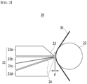
- FIG. 2 is a longitudinal sectional view illustrating a slot die coating apparatus according to the related art, which is used in a process of coating a multilayer active material.
- the slot die coating apparatus 10 includes a slot die 11, from which the electrode active material slurry is discharged, and a coating roller 12.
- the slot die 11 includes two die blocks 11a and 11b, and a discharge opening 13, from which the electrode active material slurry (not illustrated) is discharged, is formed between a first die block 11a and a second die block 11b.
- the electrode active material slurry discharged from the discharge opening 13 is applied to one surface of the collector 30 while the coating roller 12 rotates.
- an electrode active material layer constituting an additional layer is additionally applied onto an electrode active material layer constituting a single layer to form an electrode active material layer having two layers.
- the slot die 21 including four die blocks 21a, 21b, 21c, and 21d as illustrated in FIG. 2 is used.
- the slot die 21 may continuously apply an additional electrode active material slurry onto the electrode active material slurry applied in advance by simultaneously discharging the electrode active material slurry through two discharge openings 23 and 24 formed between die blocks 21a, 21b, 21c, and 21d, which are adjacent to each other.
- FIG. 3 is a picture illustrating contamination of an uncoated area, which is caused when intermittent coating is performed by using the slot die coating apparatus in FIGS. 1 and 2 .
- the uncoated area 31, in which the electrode active material slurry is not coated, is formed in the collector 30, when fully intermittent coating is performed by using the slot die coating apparatuses 10 and 20. Then, when bubbles are present in the electrode active material slurry, the bubbles burst while being discharged from the discharge openings 13, 23, and 24 in a section, in which the uncoated area 31 is formed. Then, contamination, in which the electrode active material slurry surrounding the bubbles is partially coated to the uncoated area 31 like a mottle 40, is caused.
- a distance between the discharge openings 13, 23, and 24 and the collector 30 is generally a distance D of 100 ⁇ m to 200 ⁇ m, the above-mentioned contamination is caused by fine bubbles.
- a slot die coating apparatus relates to a slot die coating apparatus for coating an electrode active material slurry onto an electrode collector, and the slot die coating apparatus including a coating roller, a lower die including a lower discharge opening, through which a second electrode active material slurry is discharged, and an upper die located on the upper side of the lower die and having an upper discharge opening, through which a first electrode active material slurry is discharged.
- An upper air vent may be installed in the upper die and a lower air vent may be installed in the lower die.
- the upper die may include a first upper die, a second upper die, and an upper spacer.
- the upper discharge opening may be formed by sequentially coupling the first upper die, the upper spacer, and the second upper die.
- An upper slurry receiving part may be formed in the second upper die.
- the upper slurry receiving part may be communicated with the upper discharge opening.
- the upper air vent may pass through the first upper die to be communicated with the upper slurry receiving part.
- the lower die may include a first lower die, a second lower die, and a lower spacer.
- the lower discharge opening may be formed by sequentially coupling the first lower die, the lower spacer, and the second lower die.
- a lower slurry receiving part may be formed in the second lower die.
- the lower slurry receiving part may be communicated with the lower discharge opening.
- the lower air vent may pass through the first upper die, the second upper die, and the first lower die to be communicated with the lower slurry receiving part.
- the lower air vent may be formed at a portion S at which the lower slurry receiving part and the lower discharge opening are connected to each other.
- the upper spacer may include a first opening and may be interposed in only the remaining part except for one side of a peripheral area in which the first upper die and the second upper die face each other.
- the upper air vent and/or the lower air vent may include a valve.
- the slot die coating apparatus 100 includes a slot die 101, a coating roller 102, and an air vent 103.
- the slot die coating apparatus 100 is used to simultaneously coat and fix two electrode active material layers.
- the slot die 101 includes an upper die 101A and a lower die 101B.
- the upper die 101A includes a first upper die 101A-1, a second upper die 101A-2, and an upper spacer 123.
- the second upper die 101A-2 may have an inclined structure, in which a surface of the second upper die 101A-2, which faces a first lower die 101B-1, has the angle of approximately 30 to 60 degrees with respect to the ground surface.
- the second upper die 101A-2 may include a recessed upper slurry receiving part 121, which has a predetermined depth on a surface of the second upper die 101A-2, which faces the first upper die 101A-1.
- the upper slurry receiving part 121 may be connected to an upper slurry supply chamber (not illustrated) installed on the outside to continuously receive a first electrode active material slurry.
- the upper slurry receiving part 121 may include an upper slurry supply port 122 communicated with the upper slurry supply chamber (not illustrated).
- the first electrode active material slurry moves in a direction, in which the coating roller 102 is installed, through an upper discharge opening 105 formed by sequentially coupling the second upper die 101A-2, the upper spacer 123, and the first upper die 101A-1 to be discharged to the outside. That is, the upper spacer 123 is interposed between the first upper die 101A-1 and the second upper die 101A-2 to form a gap between the first upper die 101A-1 and the second upper die 101A-2 so as to form a space, into which the first electrode active material slurry supplied from the upper slurry receiving part 121 can be discharged.
- the first upper die 101A-1 is located on the upper side of the second upper die 101A-2 and is coupled to the second upper die 101A-2 while the upper spacer 123 being interposed therebetween.
- a surface of the first upper die 101A-1, which faces the second upper die 101A-2, may be formed in parallel to the ground surface.
- the upper surface of the first upper die 101A-1 may be classified into two areas.
- the upper surface of the first upper die 101A-1 may include a flat portion 130 located relatively far away from the upper discharge opening 105 and an inclined portion 131 extending from the flat portion 130.
- the flat portion 130 extends to be parallel to the ground surface and the inclined portion 131 is obliquely inclined to the lower side while having an angle of approximately 30 to 60 degrees with respect to the flat portion 130.
- the first upper die 101A-1 and the second upper die 101A-2 may be formed of a metal material, and the first upper die 101A-1 and the second upper die 101A-2 may be mutually coupled to each other through bolting and the like.
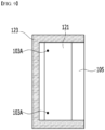
- FIG. 6 is a plan view illustrating the upper spacer of FIG. 5 .
- the upper spacer 123 may have a substantially stapler-shaped planar shape. Accordingly, the upper spacer 123 has a first opening 123a formed on one side thereof to be interposed in only the remaining parts of a periphery thereof, at which the first upper die 101A-1 and the second upper die 101A-2 face each other, except for one side thereof. Further, the first upper die 101A-1 and the second upper die 101A-2 are spaced apart from each other in an area, in which the first opening 123a is formed, to form the upper discharge opening 105 and the upper discharge opening 105 is communicated with the upper slurry receiving part 121.
- the upper spacer 123 functions as a gasket such that the first electrode active material slurry is not leaked through an aperture between the first upper die 101A-1 and the second upper die 101A-2, except for the area in which the upper discharge opening 105 is formed, it is preferable that the upper spacer 123 is formed of a material having an elasticity that can secure sealing performance.
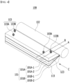
- FIG. 7 is a longitudinal sectional view when a vertical section along dotted line B of FIG. 4 is viewed from direction C.
- the lower die 101B includes a first lower die 101B-1, a second lower die 101B-2, and a lower spacer 113.
- the second lower die 101B-2 is located on the lowermost side among dies constituting the slot die 101, and may be inclined such that a surface of the second lower die 101B-2, which faces the first lower die 101B-1, has an angle of approximately 30 to 60 degrees with respect to the ground surface.
- the second lower die 101B-2 may include a recessed lower slurry receiving part 111, which has a predetermined depth on the surface of the second lower die 101B-2, which faces the first lower die 101B-1.
- the lower slurry receiving part 111 may be connected to a lower slurry supply chamber (not illustrated) to continuously receive a second electrode active material slurry.
- the lower slurry receiving part 111 may include a lower slurry supply port 112 communicated with the lower slurry supply chamber.
- the first electrode active material slurry and the second electrode active material slurry may be formed of the same component or be formed of different components according to the purpose of the manufactured electrode.
- the second electrode active material slurry may be discharged to the outside through a lower discharge opening 106 formed by sequentially coupling the second lower die 101B-2, the lower spacer 113, and the first lower die 101B-1.
- the first lower die 101B-1 is located on the upper side of the second lower die 101B-2 and is coupled to the second lower die 101B-2 while the lower spacer 113 being interposed therebetween.
- the first lower die 101B-1 and the second lower die 101B-2 may be inclined such that surfaces of the first lower die 101B-1 and the second lower die 101B-2, which face each other, have an angle of approximately 30 to 60 degrees with respect to the ground surface.
- the first lower die 101B-1 may be obliquely inclined while an upper surface of the first lower die 101B-1, which faces the upper die 101A, has an angle of approximately 30 to 60 degrees with respect to the ground surface. In this way, the upper surface of the first lower die 101B-1 is inclined with respect to the ground surface, and may be matched with the upper die 101A having a lower surface of a shape corresponding to the upper surface of the first lower die 101B-1.
- the first lower die 101B-1 and the second lower die 101B-2 may be formed of a metal material, and may be mutually coupled to each other through bolting and the like.
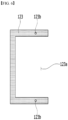
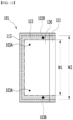
- FIG. 8 is a plan view illustrating the lower spacer of FIG. 7 .
- the lower spacer 113 is interposed between the first lower die 101B-1 and the second lower die 101B-2 to form a gap between the first lower die 101B-1 and the second lower die 101B-2 so as to form a space, into which the second electrode active material slurry is discharged.
- the lower spacer 113 has a first opening 113a formed on one side thereof to be interposed in only the remaining parts of peripheries of surfaces of the first lower die 101B-1 and the second lower die 101B-2, which face each other, except for one side thereof. Further, the first lower die 101B-1 and the second lower die 101B-2 are spaced apart from each other in an area, in which the second opening 113a is formed, to form the lower discharge opening 106 and the lower discharge opening 106 is communicated with the lower slurry receiving part 111.
- the lower spacer 113 functions as a gasket such that the second electrode active material slurry is not leaked through an aperture between the first lower die 101B-1 and the second lower die 101B-2, except for the area, in which the lower discharge opening 106 is formed, it is preferable that the lower spacer 113 is formed of a material having an elasticity that can secure sealing performance.
- the air vent 103 includes the upper air vent 103A and the lower air vent 103B.
- the upper air vent 103A passes through the first upper die 101A-1 to be communicated with the upper slurry receiving part 121. Accordingly, before the first electrode active material slurry in the upper slurry receiving part 121 is introduced into the upper discharge opening 105, bubbles in the first electrode active material slurry may be removed through the upper air vent 103A.
- the upper discharge opening 105 is formed in parallel to the ground surface, even though the upper air vent 103A is communicated with any location of the upper slurry receiving part 121, bubbles included in the first electrode active material slurry may be easily discharged to the outside through the upper air vent 103A. Meanwhile, it is preferable that the upper air vent 103A is installed in a direction that is perpendicular to a direction, in which the first electrode active material slurry is discharged, and which is opposite to a direction, in which gravity is applied, so as to efficiently remove bubbles included in the first electrode active material slurry.
- FIG. 9 is a plan view illustrating that the upper spacer is located on an second upper die. The location of the upper air vent 103A is indicated for convenience of description.
- the upper air vent 103A may be formed at rear side portions of an area formed in the upper slurry receiving part 121 in the first opening 123a of the upper spacer 123 when the second upper die 101A-2 is viewed from the top.
- the rear side refers to an opposite direction to a direction, in which the first electrode active material slurry is discharged.
- the side surface refers to opposite portions in the lengthwise direction of the second upper die 101A-2, which are perpendicular to a direction, in which the first electrode active material slurry is discharged.
- the lower air vent 103B passes through the first upper die 101A-1, the second upper die 101A-2, and the first lower die 101B-1 to be communicated with the lower slurry receiving part 111. Accordingly, before the second electrode active material slurry in the lower slurry receiving part 111 is introduced into the lower discharge opening 106, bubbles included in the second electrode active material slurry may be removed through the lower air vent 103B.
- the lower discharge opening 106 is inclined at an angle of 30 to 60 degrees with respect to the ground surface and has a structure, in which the second electrode active material slurry is supplied to lower slurry receiving part 111 in an opposite direction to the gravitational force in the lower slurry port 112, the largest number of bubbles are generated in portion S of the lower slurry receiving part 111, which is connected to the lower discharge opening 106. Accordingly, it is preferable that the lower air vent 103B is installed in portion S.
- the angle between the lower air vent 103B and the lower discharge opening 106 is maintained at 80 to 150 degrees.
- FIG. 10 is a plan view illustrating that the lower spacer is located on a second lower die. The location of the lower air vent 103B is indicated for convenience of description.
- FIG. 11 is a plan view of a slot die of FIG. 4 .
- a boundary of the first opening 123a of the upper spacer 123 is indicated by an alternate long and short dash line, and a boundary of the second opening 113a of the lower spacer 113 is indicated by a dotted line.
- the lower air vent 103B is installed not to pass through the upper discharge opening 105 and the upper slurry receiving part 121.
- the lower air vent 103B passes through portions, at which the upper discharge opening 105 and the upper slurry receiving part 121 are formed, it may hamper flows of the first electrode active material slurry and bubbles may be formed at the passing -through portions. Accordingly, it is preferable that the lower air vent 103B is formed to pass through the location, at which the upper spacer 123 deviates from the first opening 123a.
- the length W1 of the first opening 123a of the upper spacer 123 is formed to be smaller than the length W2 of the second opening 113a of the lower spacer 113 so that the lower air vent 103B may be formed to pass through the through-hole 123b of the upper spacer 123.
- the lower air vent 103B may be formed at portions that are close to side surfaces of the first upper die 101A-1 in the lengthwise direction of the first upper die 101A-1, which is perpendicular to a direction, in which the second electrode active material slurry is discharged.
- the location of the lower air vent 103B does not hamper the operator's movements and facilitates the maintenance and repair of the slot die coating apparatus 100.
- the lower air vent 103B may be formed in various directions.
- the lower air vent 103B may pass through the second upper die 101A-2 and the first lower die 101B-1 to be formed in a rearward direction thereof (see D of FIG. 7 ).
- the lower air vent 103B may be installed at various locations on lateral sides.
- the lower air vent 103B may be also formed on lateral sides.
- FIG. 12 is a longitudinal sectional view illustrating a modification of FIG. 5 .
- a slot die coating apparatus 200 may have a structure, in which an upper air vent 203A is bent in an inverse L shape.
- an upper air vent 203A is bent in an inverse L shape.
- the bubbles are discharged together with the first electrode active material slurry. Then, the operator may easily receive the first electrode active material slurry that flows down through the bent upper air vent 203A.
- FIG. 12 illustrates only the bent structure that is bent in an inverse L shape, as long as the first electrode active material slurry flowing down may be easily received, the upper air vent 203A may be bent in various shapes.
- the upper air vent 203A may include a valve 240.
- the valve 240 has any structure that may open and close a hollowed pipeline, it is not specifically limited.
- the slot die coating apparatus 200 may have the same structure as the slot die coating apparatus 100 of FIG. 5 , except for the structure, in which the upper air vent 203A is bent in an inverse L shape, and includes the valve 240. Accordingly, a description of other configurations will be omitted.
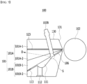
- FIG. 13 is a longitudinal sectional view illustrating a modification of FIG. 7 .
- a slot die coating apparatus 200 may have a structure, in which a lower air vent 203B is bent in an inverse L shape.
- a lower air vent 203B is bent in an inverse L shape.
- the bubbles are discharged together with the second electrode active material slurry. Then, the operator may easily receive the second electrode active material slurry that flows down through the bent lower air vent 203B.
- FIG. 13 illustrates only a structure that is bent in an inverse L shape, as long as the second electrode active material slurry running down may be easily received, the lower air vent 203B can be bent in various shapes.
- the lower air vent 203B may include a valve 240.
- the valve 240 has any structure that may open and close a hollowed pipeline, it is not specifically limited.
- the slot die coating apparatus 200 may have the same structure as the slot die coating apparatus 100 of FIG. 7 , except for a structure, in which the lower air vent 203B is bent in an inverse L shape, and includes the valve 240. Accordingly, a description of other configurations will be omitted.
- An installation structure of air vents 103, 203A, and 203B according to the present disclosure may be applied to the slot die coating apparatus used in a process of coating a single layer active material in FIG. 1 . In this case, it may be formed as in the upper air vent 103A of FIG. 5 .
- the relevant structure has already been described and will be omitted here.
- the installation structure of air vents 103, 203A, and 203B according to the present disclosure may be applied to a 3-stage slot die coating apparatus, in which the second upper die 101A-2 and the first lower die 101B-1 are integrally formed. It may have the same structure as FIGS. 5 , 7 , 12 , and 13 , except for a structure, in which the second upper die 101A-2 and the first lower die 101B-1 are integrally formed.
- the slot die coating apparatuses 100 and 200 may prevent contamination of the uncoated area, which is caused when intermittent coating is performed, and may also solve non-coating of an active material caused due to continuous coating.
- the electrode active material slurry including bubbles is applied to an electrode in the continuous coating process, if the bubbles surrounded by slurry burst, a portion, at which the active material is not coated, is caused in the spot, such as a crater, at which the bubbles was present.
- a slot die coating apparatus for coating an electrode active material slurry onto an electrode collector, the slot die coating apparatus comprising:
- Item 2 The slot die coating apparatus of item 1, wherein the upper die comprises an first upper die, an second upper die, and an upper spacer, and
- Item 3 The slot die coating apparatus of item 2, wherein the upper discharge opening is formed by sequentially coupling the first upper die, the upper spacer, and the second upper die.
- Item 4 The slot die coating apparatus of item 3, wherein an upper slurry receiving part is formed in the second upper die.
- Item 5 The slot die coating apparatus of item 4, wherein the upper slurry receiving part is communicated with the upper discharge opening.
- Item 6 The slot die coating apparatus of item 3, wherein the upper air vent passes through the first upper die to be communicated with the upper slurry receiving part.
- Item 7 The slot die coating apparatus of item 2, wherein the lower die comprises a first lower die, a second lower die, and a lower spacer.
- Item 8 The slot die coating apparatus of item 7, wherein the lower discharge opening is formed by sequentially coupling the first lower die, the lower spacer, and the second lower die.
- Item 9 The slot die coating apparatus of item 8, wherein a lower slurry receiving part is formed in the second lower die.
- Item 10 The slot die coating apparatus of item 9, wherein the lower slurry receiving part is communicated with the lower discharge opening.
- Item 11 The slot die coating apparatus of item 10, wherein the lower air vent passes through the first upper die, the second upper die, and first lower die to be communicated with the lower slurry receiving part.
- Item 12 The slot die coating apparatus of item 10, wherein the lower air vent passes through the second upper die and the first lower die to be communicated with the lower slurry receiving part.
- Item 13 The slot die coating apparatus of item 11, wherein the lower air vent is formed at a portion (S), at which the lower slurry receiving part and the lower discharge opening are connected to each other.
- Item 14 The slot die coating apparatus of item 2, wherein the upper spacer comprises a first opening and is interposed in only the remaining part except for one side of a peripheral area, in which the first upper die and the second upper die face each other.
- Item. 15 The slot die coating apparatus of item 13, wherein the lower air vent is installed to pass through the upper spacer.
- Item 16 The slot die coating apparatus of item 1, wherein the upper air vent and/or the lower air vent comprises a valve.
- Item 17 The slot die coating apparatus of item 1, wherein the upper air vent and/or the lower air vent has a bent structure.
- Item 18 A slot die coating apparatus (100) for coating an electrode active material slurry onto an electrode collector, the slot die coating apparatus comprising:
- Item 19 The slot die coating apparatus of item 18, wherein the upper die comprises an first upper die (101A-1), an second upper die (101A-2), and an upper spacer (123), and wherein the upper discharge opening (105) is formed by sequentially coupling the first upper die (101A-1), the upper spacer (123), and the second upper die (101A-2).
- Item 20 The slot die coating apparatus of item 19, wherein an upper slurry receiving part (121) is formed in the second upper die (101A-2).
- Item 21 The slot die coating apparatus of item 20, wherein the upper slurry receiving part (121) is communicated with the upper discharge opening (105).
- Item 24 The slot die coating apparatus of item 23, wherein the lower slurry receiving part (111) is formed in the second lower die (101B-2).
- Item 27 The slot die coating apparatus of item 19, wherein the upper spacer comprises a first opening and is interposed in only the remaining part except for one side of a peripheral area, in which the first upper die (101A-1) and the second upper die (101A-2) face each other.
- Item 28 The slot die coating apparatus of item 19, wherein the lower air vent (103B) is installed to pass through the upper spacer (123).
- Item 29 The slot die coating apparatus of item 18, wherein the upper air vent (103A) and/or the lower air vent (103B) comprises a valve.
- Item 30 The slot die coating apparatus of item 18, wherein the upper air vent (203A) and/or the lower air vent (203B) has a bent structure.
Landscapes
- Engineering & Computer Science (AREA)
- Manufacturing & Machinery (AREA)
- Chemical & Material Sciences (AREA)
- Chemical Kinetics & Catalysis (AREA)
- Electrochemistry (AREA)
- General Chemical & Material Sciences (AREA)
- Coating Apparatus (AREA)
- Battery Electrode And Active Subsutance (AREA)
- Secondary Cells (AREA)
Applications Claiming Priority (4)
| Application Number | Priority Date | Filing Date | Title |
|---|---|---|---|
| KR1020190056451A KR102368359B1 (ko) | 2019-05-14 | 2019-05-14 | 에어 벤트를 포함하는 슬롯 다이 코팅 장치 |
| EP23182536.5A EP4243110B1 (de) | 2019-05-14 | 2020-05-12 | Schlitzdüsenbeschichtungseinrichtung mit entlüftung |
| PCT/KR2020/006208 WO2020231141A1 (ko) | 2019-05-14 | 2020-05-12 | 에어 벤트를 포함하는 슬롯 다이 코팅 장치 |
| EP20805781.0A EP3915687B1 (de) | 2019-05-14 | 2020-05-12 | Schlitzdüsenbeschichtungseinrichtung mit entlüftung |
Related Parent Applications (2)
| Application Number | Title | Priority Date | Filing Date |
|---|---|---|---|
| EP23182536.5A Division EP4243110B1 (de) | 2019-05-14 | 2020-05-12 | Schlitzdüsenbeschichtungseinrichtung mit entlüftung |
| EP20805781.0A Division EP3915687B1 (de) | 2019-05-14 | 2020-05-12 | Schlitzdüsenbeschichtungseinrichtung mit entlüftung |
Publications (2)
| Publication Number | Publication Date |
|---|---|
| EP4517853A2 true EP4517853A2 (de) | 2025-03-05 |
| EP4517853A3 EP4517853A3 (de) | 2025-05-21 |
Family
ID=73290242
Family Applications (3)
| Application Number | Title | Priority Date | Filing Date |
|---|---|---|---|
| EP25151874.2A Pending EP4517853A3 (de) | 2019-05-14 | 2020-05-12 | Schlitzdüsenbeschichtungsvorrichtung mit entlüftung |
| EP20805781.0A Active EP3915687B1 (de) | 2019-05-14 | 2020-05-12 | Schlitzdüsenbeschichtungseinrichtung mit entlüftung |
| EP23182536.5A Active EP4243110B1 (de) | 2019-05-14 | 2020-05-12 | Schlitzdüsenbeschichtungseinrichtung mit entlüftung |
Family Applications After (2)
| Application Number | Title | Priority Date | Filing Date |
|---|---|---|---|
| EP20805781.0A Active EP3915687B1 (de) | 2019-05-14 | 2020-05-12 | Schlitzdüsenbeschichtungseinrichtung mit entlüftung |
| EP23182536.5A Active EP4243110B1 (de) | 2019-05-14 | 2020-05-12 | Schlitzdüsenbeschichtungseinrichtung mit entlüftung |
Country Status (9)
| Country | Link |
|---|---|
| US (2) | US11819876B2 (de) |
| EP (3) | EP4517853A3 (de) |
| JP (1) | JP7134551B2 (de) |
| KR (1) | KR102368359B1 (de) |
| CN (1) | CN113646093B (de) |
| ES (2) | ES2972883T3 (de) |
| HU (2) | HUE070686T2 (de) |
| PL (2) | PL3915687T3 (de) |
| WO (1) | WO2020231141A1 (de) |
Families Citing this family (9)
| Publication number | Priority date | Publication date | Assignee | Title |
|---|---|---|---|---|
| KR102368359B1 (ko) * | 2019-05-14 | 2022-02-25 | 주식회사 엘지에너지솔루션 | 에어 벤트를 포함하는 슬롯 다이 코팅 장치 |
| KR102733885B1 (ko) * | 2019-09-06 | 2024-11-22 | 주식회사 엘지에너지솔루션 | 에어 벤트를 포함하는 슬롯 다이 코팅 장치 |
| US12533703B2 (en) * | 2020-11-11 | 2026-01-27 | Panasonic Intellectual Property Management Co., Ltd. | Electrode mixture slurry coating device |
| US12377435B2 (en) | 2020-11-13 | 2025-08-05 | Lg Energy Solution, Ltd. | Dual slot die coater including air vent |
| CN112378815B (zh) * | 2020-11-27 | 2025-11-28 | 河北格力钛新能源有限公司 | 锂电池浆料检测装置及检测方法 |
| KR20220094459A (ko) * | 2020-12-29 | 2022-07-06 | 주식회사 엘지에너지솔루션 | 듀얼 슬롯 다이 코터 |
| CN112871579A (zh) * | 2021-03-23 | 2021-06-01 | 深圳市曼恩斯特科技股份有限公司 | 一种双层涂布模头及涂布机 |
| CN113210198A (zh) * | 2021-04-27 | 2021-08-06 | 深圳顺络电子股份有限公司 | 一种流延设备 |
| KR102656809B1 (ko) * | 2022-04-05 | 2024-04-12 | 주식회사 엘지에너지솔루션 | 활물질의 다층 코팅이 가능한 다이 코터 |
Citations (1)
| Publication number | Priority date | Publication date | Assignee | Title |
|---|---|---|---|---|
| KR20190056451A (ko) | 2017-11-03 | 2019-05-27 | 동명대학교산학협력단 | 스마트 물류 센터 운영 시스템 |
Family Cites Families (22)
| Publication number | Priority date | Publication date | Assignee | Title |
|---|---|---|---|---|
| JPS6046573B2 (ja) * | 1980-11-17 | 1985-10-16 | 三洋電機株式会社 | タイマ回路 |
| JPS6055280B2 (ja) * | 1981-04-30 | 1985-12-04 | リヒト産業株式会社 | 事務用穿孔機 |
| WO1999034932A1 (en) * | 1998-01-09 | 1999-07-15 | Fastar, Ltd. | Moving head, coating apparatus and method |
| US7083826B2 (en) | 2003-05-16 | 2006-08-01 | 3M Innovative Properties Company | Coating die and method for use |
| JP4835003B2 (ja) | 2005-02-07 | 2011-12-14 | 凸版印刷株式会社 | スリットノズル及びスリットノズルの気泡排出方法並びに塗布装置 |
| JP5202838B2 (ja) | 2006-12-12 | 2013-06-05 | 東京応化工業株式会社 | スリットノズル |
| KR101097525B1 (ko) | 2009-07-03 | 2011-12-22 | 한화테크엠주식회사 | 패턴 코팅 장치 |
| KR101212201B1 (ko) | 2010-07-02 | 2012-12-13 | 삼성에스디아이 주식회사 | 활물질 코팅 장치 |
| JP5774298B2 (ja) | 2010-12-08 | 2015-09-09 | 日東電工株式会社 | 塗布物の製造方法及び製造装置 |
| KR101107651B1 (ko) * | 2011-07-27 | 2012-01-20 | 성안기계 (주) | 도포 균일성이 향상된 슬롯다이 |
| JP2013188663A (ja) | 2012-03-13 | 2013-09-26 | Toppan Printing Co Ltd | 間欠塗布装置 |
| JP6055280B2 (ja) | 2012-11-11 | 2016-12-27 | 平田機工株式会社 | 塗布液充填方法 |
| JP6212951B2 (ja) | 2013-05-22 | 2017-10-18 | 凸版印刷株式会社 | 電池用電極部材の製造方法 |
| JP6046573B2 (ja) | 2013-08-23 | 2016-12-21 | オリジン電気株式会社 | ダイヘッド、塗工液塗布装置、塗工液塗布部材の製造方法及び塗工液塗布方法 |
| JP6196916B2 (ja) | 2014-02-25 | 2017-09-13 | 東京応化工業株式会社 | ノズルおよび塗布装置 |
| KR20150105794A (ko) | 2014-03-10 | 2015-09-18 | 주식회사 엘지화학 | 전극 생산용 슬롯 다이 코터 |
| JP6367075B2 (ja) | 2014-10-08 | 2018-08-01 | 株式会社ヒラノテクシード | ダイとダイの空気抜き方法 |
| KR101692525B1 (ko) * | 2015-02-13 | 2017-01-03 | 주식회사 엔씨에스 | 슬릿 코터용 슬릿 노즐 및 이를 사용한 약액 공급 시스템 |
| US10675654B2 (en) * | 2017-03-01 | 2020-06-09 | Nordson Corporation | Multi-layer slot die system and method |
| KR102190114B1 (ko) | 2017-08-17 | 2020-12-11 | 주식회사 엘지화학 | 슬롯들의 움직임으로 전극 활물질 슬러리의 코팅 형태가 변환되는 슬롯 다이 코터 |
| CN109261438B (zh) | 2018-09-26 | 2020-08-11 | 深圳市曼恩斯特科技有限公司 | 涂布模头及涂布机 |
| KR102368359B1 (ko) * | 2019-05-14 | 2022-02-25 | 주식회사 엘지에너지솔루션 | 에어 벤트를 포함하는 슬롯 다이 코팅 장치 |
-
2019
- 2019-05-14 KR KR1020190056451A patent/KR102368359B1/ko active Active
-
2020
- 2020-05-12 US US17/431,561 patent/US11819876B2/en active Active
- 2020-05-12 HU HUE23182536A patent/HUE070686T2/hu unknown
- 2020-05-12 CN CN202080012154.6A patent/CN113646093B/zh active Active
- 2020-05-12 ES ES20805781T patent/ES2972883T3/es active Active
- 2020-05-12 EP EP25151874.2A patent/EP4517853A3/de active Pending
- 2020-05-12 PL PL20805781.0T patent/PL3915687T3/pl unknown
- 2020-05-12 JP JP2021513806A patent/JP7134551B2/ja active Active
- 2020-05-12 EP EP20805781.0A patent/EP3915687B1/de active Active
- 2020-05-12 WO PCT/KR2020/006208 patent/WO2020231141A1/ko not_active Ceased
- 2020-05-12 PL PL23182536.5T patent/PL4243110T3/pl unknown
- 2020-05-12 EP EP23182536.5A patent/EP4243110B1/de active Active
- 2020-05-12 ES ES23182536T patent/ES3014084T3/es active Active
- 2020-05-12 HU HUE20805781A patent/HUE065561T2/hu unknown
-
2023
- 2023-10-13 US US18/379,836 patent/US20240033772A1/en active Pending
Patent Citations (1)
| Publication number | Priority date | Publication date | Assignee | Title |
|---|---|---|---|---|
| KR20190056451A (ko) | 2017-11-03 | 2019-05-27 | 동명대학교산학협력단 | 스마트 물류 센터 운영 시스템 |
Also Published As
| Publication number | Publication date |
|---|---|
| PL3915687T3 (pl) | 2024-04-22 |
| EP3915687A1 (de) | 2021-12-01 |
| EP4243110A2 (de) | 2023-09-13 |
| WO2020231141A1 (ko) | 2020-11-19 |
| ES2972883T3 (es) | 2024-06-17 |
| EP4243110A3 (de) | 2023-12-13 |
| PL4243110T3 (pl) | 2025-04-14 |
| US20220134378A1 (en) | 2022-05-05 |
| EP4243110B1 (de) | 2025-02-12 |
| US20240033772A1 (en) | 2024-02-01 |
| EP4517853A3 (de) | 2025-05-21 |
| KR102368359B1 (ko) | 2022-02-25 |
| JP7134551B2 (ja) | 2022-09-12 |
| CN113646093B (zh) | 2022-12-27 |
| US11819876B2 (en) | 2023-11-21 |
| EP3915687A4 (de) | 2022-04-13 |
| JP2022501177A (ja) | 2022-01-06 |
| KR20200131620A (ko) | 2020-11-24 |
| HUE070686T2 (hu) | 2025-06-28 |
| CN113646093A (zh) | 2021-11-12 |
| HUE065561T2 (hu) | 2024-06-28 |
| EP3915687B1 (de) | 2024-02-21 |
| ES3014084T3 (en) | 2025-04-16 |
Similar Documents
| Publication | Publication Date | Title |
|---|---|---|
| EP3915687B1 (de) | Schlitzdüsenbeschichtungseinrichtung mit entlüftung | |
| EP3549678B1 (de) | Schlitzdüsenbeschichter zum ändern der beschichtungsform einer elektrodenaktivmaterialaufschlämmung durch bewegung der schlitze | |
| US20240299972A1 (en) | Slot Die Coating Device Having Air Vent | |
| US10062897B2 (en) | Battery electrode and a method for producing same | |
| KR101256069B1 (ko) | 전극 조립체와 이를 적용한 이차전지 | |
| US20210313552A1 (en) | Coating Apparatus | |
| KR101850180B1 (ko) | 관통구가 천공되어 있는 집전체를 포함하는 이차전지 | |
| US20240322261A1 (en) | Electrode assembly, battery cell, battery, and electric apparatus | |
| KR20100033831A (ko) | 전지 셀 및 전지 셀을 구비한 전지 팩 | |
| KR102227310B1 (ko) | 전극 제조용 슬롯 다이 | |
| KR101998585B1 (ko) | 함침의 향상을 위해 진동을 이용하는 전지셀 제조용 전해액 함침 장치 | |
| KR102704957B1 (ko) | 전해액 함침 장치 및 전해액 함침 방법 | |
| KR20200058752A (ko) | 이차 전지의 제조 방법 | |
| KR101514875B1 (ko) | 이차 전지 | |
| US20230327298A1 (en) | Electrode for secondary battery and method of manufacturing the same | |
| KR100717761B1 (ko) | 활물질 코팅 장치 | |
| EP4273982A1 (de) | Jelly-roll-elektrodenanordnung und sekundärbatterie damit | |
| KR20180137798A (ko) | 미코팅부 형성용 코팅 다이를 구비한 전극 코팅 장치 및 이를 이용한 전극 제조 방법 및 이로부터 제조된 전극 | |
| KR102801794B1 (ko) | 자기 배향 장치 | |
| KR20080037863A (ko) | 원통형 이차 전지 | |
| KR20240100932A (ko) | 파우치 셀 | |
| KR20230057693A (ko) | 전극 코팅 슬러리 공급 펌프용 맥동저감장치 |
Legal Events
| Date | Code | Title | Description |
|---|---|---|---|
| PUAI | Public reference made under article 153(3) epc to a published international application that has entered the european phase |
Free format text: ORIGINAL CODE: 0009012 |
|
| STAA | Information on the status of an ep patent application or granted ep patent |
Free format text: STATUS: REQUEST FOR EXAMINATION WAS MADE |
|
| 17P | Request for examination filed |
Effective date: 20250114 |
|
| AC | Divisional application: reference to earlier application |
Ref document number: 3915687 Country of ref document: EP Kind code of ref document: P Ref document number: 4243110 Country of ref document: EP Kind code of ref document: P |
|
| AK | Designated contracting states |
Kind code of ref document: A2 Designated state(s): AL AT BE BG CH CY CZ DE DK EE ES FI FR GB GR HR HU IE IS IT LI LT LU LV MC MK MT NL NO PL PT RO RS SE SI SK SM TR |
|
| REG | Reference to a national code |
Ref country code: DE Ref legal event code: R079 Free format text: PREVIOUS MAIN CLASS: H01M0004040000 Ipc: B05C0005020000 |
|
| PUAL | Search report despatched |
Free format text: ORIGINAL CODE: 0009013 |
|
| AK | Designated contracting states |
Kind code of ref document: A3 Designated state(s): AL AT BE BG CH CY CZ DE DK EE ES FI FR GB GR HR HU IE IS IT LI LT LU LV MC MK MT NL NO PL PT RO RS SE SI SK SM TR |
|
| RIC1 | Information provided on ipc code assigned before grant |
Ipc: H01M 4/04 20060101ALI20250411BHEP Ipc: B05C 5/02 20060101AFI20250411BHEP |
|
| GRAP | Despatch of communication of intention to grant a patent |
Free format text: ORIGINAL CODE: EPIDOSNIGR1 |
|
| STAA | Information on the status of an ep patent application or granted ep patent |
Free format text: STATUS: GRANT OF PATENT IS INTENDED |
|
| INTG | Intention to grant announced |
Effective date: 20260223 |