EP4516409A1 - Druckakkumulierende sprühvorrichtung - Google Patents
Druckakkumulierende sprühvorrichtung Download PDFInfo
- Publication number
- EP4516409A1 EP4516409A1 EP23796351.7A EP23796351A EP4516409A1 EP 4516409 A1 EP4516409 A1 EP 4516409A1 EP 23796351 A EP23796351 A EP 23796351A EP 4516409 A1 EP4516409 A1 EP 4516409A1
- Authority
- EP
- European Patent Office
- Prior art keywords
- valve
- valve structure
- cylinder
- liquid
- spring
- Prior art date
- Legal status (The legal status is an assumption and is not a legal conclusion. Google has not performed a legal analysis and makes no representation as to the accuracy of the status listed.)
- Pending
Links
Images


Classifications
-
- B—PERFORMING OPERATIONS; TRANSPORTING
- B05—SPRAYING OR ATOMISING IN GENERAL; APPLYING FLUENT MATERIALS TO SURFACES, IN GENERAL
- B05B—SPRAYING APPARATUS; ATOMISING APPARATUS; NOZZLES
- B05B11/00—Single-unit hand-held apparatus in which flow of contents is produced by the muscular force of the operator at the moment of use
- B05B11/01—Single-unit hand-held apparatus in which flow of contents is produced by the muscular force of the operator at the moment of use characterised by the means producing the flow
- B05B11/10—Pump arrangements for transferring the contents from the container to a pump chamber by a sucking effect and forcing the contents out through the dispensing nozzle
- B05B11/1001—Piston pumps
- B05B11/1021—Piston pumps having an outlet valve which is a gate valve
- B05B11/1022—Piston pumps having an outlet valve which is a gate valve actuated by pressure
-
- B—PERFORMING OPERATIONS; TRANSPORTING
- B05—SPRAYING OR ATOMISING IN GENERAL; APPLYING FLUENT MATERIALS TO SURFACES, IN GENERAL
- B05B—SPRAYING APPARATUS; ATOMISING APPARATUS; NOZZLES
- B05B11/00—Single-unit hand-held apparatus in which flow of contents is produced by the muscular force of the operator at the moment of use
- B05B11/01—Single-unit hand-held apparatus in which flow of contents is produced by the muscular force of the operator at the moment of use characterised by the means producing the flow
- B05B11/10—Pump arrangements for transferring the contents from the container to a pump chamber by a sucking effect and forcing the contents out through the dispensing nozzle
- B05B11/1001—Piston pumps
- B05B11/1009—Piston pumps actuated by a lever
- B05B11/1011—Piston pumps actuated by a lever without substantial movement of the nozzle in the direction of the pressure stroke
-
- B—PERFORMING OPERATIONS; TRANSPORTING
- B05—SPRAYING OR ATOMISING IN GENERAL; APPLYING FLUENT MATERIALS TO SURFACES, IN GENERAL
- B05B—SPRAYING APPARATUS; ATOMISING APPARATUS; NOZZLES
- B05B11/00—Single-unit hand-held apparatus in which flow of contents is produced by the muscular force of the operator at the moment of use
- B05B11/01—Single-unit hand-held apparatus in which flow of contents is produced by the muscular force of the operator at the moment of use characterised by the means producing the flow
- B05B11/10—Pump arrangements for transferring the contents from the container to a pump chamber by a sucking effect and forcing the contents out through the dispensing nozzle
- B05B11/1042—Components or details
- B05B11/1052—Actuation means
- B05B11/1056—Actuation means comprising rotatable or articulated levers
- B05B11/1057—Triggers, i.e. actuation means consisting of a single lever having one end rotating or pivoting around an axis or a hinge fixedly attached to the container, and another end directly actuated by the user
-
- B—PERFORMING OPERATIONS; TRANSPORTING
- B05—SPRAYING OR ATOMISING IN GENERAL; APPLYING FLUENT MATERIALS TO SURFACES, IN GENERAL
- B05B—SPRAYING APPARATUS; ATOMISING APPARATUS; NOZZLES
- B05B11/00—Single-unit hand-held apparatus in which flow of contents is produced by the muscular force of the operator at the moment of use
- B05B11/01—Single-unit hand-held apparatus in which flow of contents is produced by the muscular force of the operator at the moment of use characterised by the means producing the flow
- B05B11/10—Pump arrangements for transferring the contents from the container to a pump chamber by a sucking effect and forcing the contents out through the dispensing nozzle
- B05B11/1042—Components or details
- B05B11/1073—Springs
- B05B11/1074—Springs located outside pump chambers
-
- B—PERFORMING OPERATIONS; TRANSPORTING
- B05—SPRAYING OR ATOMISING IN GENERAL; APPLYING FLUENT MATERIALS TO SURFACES, IN GENERAL
- B05B—SPRAYING APPARATUS; ATOMISING APPARATUS; NOZZLES
- B05B11/00—Single-unit hand-held apparatus in which flow of contents is produced by the muscular force of the operator at the moment of use
- B05B11/0005—Components or details
- B05B11/0008—Sealing or attachment arrangements between sprayer and container
-
- B—PERFORMING OPERATIONS; TRANSPORTING
- B05—SPRAYING OR ATOMISING IN GENERAL; APPLYING FLUENT MATERIALS TO SURFACES, IN GENERAL
- B05B—SPRAYING APPARATUS; ATOMISING APPARATUS; NOZZLES
- B05B11/00—Single-unit hand-held apparatus in which flow of contents is produced by the muscular force of the operator at the moment of use
- B05B11/01—Single-unit hand-held apparatus in which flow of contents is produced by the muscular force of the operator at the moment of use characterised by the means producing the flow
- B05B11/10—Pump arrangements for transferring the contents from the container to a pump chamber by a sucking effect and forcing the contents out through the dispensing nozzle
- B05B11/1042—Components or details
- B05B11/1073—Springs
- B05B11/1077—Springs characterised by a particular shape or material
Definitions
- the present invention relates to an accumulator sprayer and, in more detail, to an accumulator sprayer that eliminates the pressing force (i.e., initial set pressure) applied to a valve structure when a trigger is not pulled (initial set state, i.e., when the valve is not open), and thereby suppresses deformation of the valve structure.
- pressing force i.e., initial set pressure
- This accumulator spray is configured to increase the pressure of the liquid inside a cylinder by pulling back the trigger and sliding a piston against the cylinder, and then to forcefully spray the liquid inside the cylinder out of the nozzle when the pressure exceeds a certain level.
- the cylinder is located between two one-way valves (i.e. a first valve and a second valve), and when the accumulated pressure of the liquid in the cylinder, which has been introduced via the first valve, exceeds a certain level, a space between a valve body and a valve seat of the second valve is released and the valve is opened, then the liquid is forcefully pushed out of the cylinder and sprayed outwards via the nozzle.
- two one-way valves i.e. a first valve and a second valve
- valve body of the second valve is always pressed against the valve seat by the resilient force of a spring, and when the fluid pressure inside the cylinder exceeds the resilient force in a state in which the first valve is closed, the second valve opens and the fluid passes through forcefully.
- the accumulator sprayer including the trigger is useful because it can forcefully splay the liquid in the cylinder to the outside in this manner.
- the invention in PTL 1 is a trigger sprayer for sucking up and splay liquid in a container, and has a second valve that opens and closes according to the pressure of the liquid, and the second valve has a second valve piston portion and an inverted-dome-shaped dome spring portion for applying force to the second valve piston portion.
- the invention of PTL 2 is similar.
- the pressing force applied to the valve body in the initial set state is referred to as the "initial set pressure.”
- the spring portion is always loaded by a certain initial set pressure even in the initial set state, which causes plastic deformation of the spring portion.
- the resilient force of the spring portion itself is degraded and the valve becomes less tight, resulting in inappropriate liquid spraying and leakage.
- the present invention was developed in response to the above-mentioned problem. That is, the purpose of the present invention is to provide an accumulator sprayer that can eliminate the initial set pressure applied to the spring portion in the initial set state and thereby suppress plastic deformation of the valve structure (valve body) containing the spring portion as much as possible.
- the present inventors have conducted extensive research and has found that the above problem can be solved by making the length L1 of the valve structure in unloaded state and the shortest distance L2 between a lower support portion and an upper support portion to which the valve structure is attached satisfy the relationship L1 ⁇ L2.
- the present invention is based on this finding.
- the present invention resides in an accumulator sprayer mounted with a valve structure, wherein the valve structure is mounted so as not to contact at least one of an upper support portion, which is a portion supporting the valve structure on the upper side, and a lower support portion, which is a portion supporting the valve structure on the lower side, in an initial set state.
- the present invention resides in an accumulator sprayer X comprising a cylinder body portion B having a main cylinder portion B1 and a sub-cylinder portion B2, and a cover portion C attached to cover the cylinder body portion B, wherein the accumulator sprayer X is attached to a container J to suck up liquid in the container J to the main cylinder portion B1 via a first valve FV, apply pressure to the liquid in the main cylinder portion B1, and spray the liquid from a nozzle portion F via the valve structure A when the pressure exceeds a certain pressure, and the valve structure A is mounted between a lower support portion B23 of the sub-cylinder portion B2 and an upper support portion C1 of the cover portion C, and a length L1 of the valve structure A in unloaded state and a shortest distance L2 between the lower support portion B23 and the upper support portion C1 satisfy the relational expression L1 ⁇ L2.
- the present invention resides in the above-described accumulator sprayer X, wherein the valve structure A is composed of a reverse-dome-shaped spring portion 1 and a valve piston portion 2 hanging down from the spring portion 1, and the valve piston portion 2 is composed of a core rod portion 21, an outer skirt portion 22 extending downward from the outer circumference of the core rod portion 21, and an inner skirt portion 23 longer than the outer skirt portion 22.
- the present invention resides in the above-described accumulator sprayer X, wherein the core rod portion 21 is formed cylindrically between the spring portion 1 and the outer skirt portion 22.
- the present invention resides in the above-described accumulator sprayer X, wherein a tubular protrusion 1A is formed in the center of the spring portion 1.
- the present invention resides in the above-described accumulator sprayer X, wherein a center hole 1B whose top is open is formed in the valve piston portion 2.
- the accumulator sprayer X of the present invention can reduce the initial set pressure and thereby suppress the plastic deformation of the valve structure as much as possible since the valve structure is mounted so as not to contact at least one of the upper support portion and the lower support portion in the initial set state.
- the accumulator sprayer X of the present invention can set the pressing force applied to the valve piston portion 2 in the initial set state to zero (i.e., set the initial set pressure to zero) since the length L1 of the valve structure A in unloaded state and the shortest distance L2 between the lower support portion B23 and the upper support portion C1, the valve structure A is mounted therebetween, satisfy the relational expression L1 ⁇ L2. Therefore, the load applied to the valve structure A in the initial set state is reduced, and its plastic deformation can be suppressed as much as possible.
- the unloaded state described herein is the state in which the valve structure A is not pressed neither in a valve-opening direction nor a valve-closing direction.
- valve structure A is composed of a reverse-dome-shaped spring portion 1 and a valve piston portion 2 hanging down from the spring portion 1, the resilient force of the spring portion 1 is applied evenly to the valve piston portion 2. Therefore, the pressing force can be transmitted properly, the axial center of the valve piston portion 2 is stabilized, and lateral movement during vertical movement is prevented.
- the core rod portion 21 is formed cylindrically between the spring portion 1 and the outer skirt portion 22, when the valve structure A moves upward and downward, no obstacle contacts with the wall surface of the sub-cylinder portion B2 and its movement is not interfered, therefore the opening and closing of the valve is smoothly performed by the valve structure A.
- the tubular protrusion 1A is formed in the center of the spring portion 1, when the valve structure A comes up to an upper dead point, the deformation of the spring portion 1 is suppressed within a certain range, thereby the load applied to the spring portion 1 can be reduced.
- the weight of the valve structure A can be reduced. In addition, axial bending is prevented when the valve structure A is pressed.
- the accumulator sprayer X of the present invention is attached to a container J, sucks up liquid in the container J into a main cylinder portion B1 via a first valve FV, applies pressure to the liquid in the main cylinder portion B1, and when the liquid pressure exceeds a certain pressure, the liquid is sprayed forcefully from a nozzle portion F via the valve structure A.
- FIG. 1 is a longitudinal sectional view showing an accumulator sprayer of the present invention.
- FIG. 2 is an enlarged longitudinal sectional view showing the valve structure in the state shown in FIG. 1 .
- the accumulator sprayer X includes the nozzle portion F, a cylinder body portion B (including the main cylinder portion B1, a sub-cylinder portion B2, a first passage portion P1, a second passage portion P2, and a third passage portion P3, etc.), a piston portion D, a cover portion C, a trigger portion E, the first valve FV, a second valve, an introduction tube H, a trigger-returning spring I, and a cap portion G.
- the cylinder body portion B is a portion that has a passage through which the liquid flows, and includes the main cylinder portion B1 for accommodating the piston portion D, the first passage portion P1 for introducing the liquid from the container J into the main cylinder portion B1, the second passage portion P2 for introducing the liquid from the main cylinder portion B1 into the sub-cylinder portion B2 to which the valve structure A is attached, and the third passage portion P3 for introducing the liquid from the sub-cylinder portion B2 into the nozzle portion F.
- the introduction tube H is cylindrical shape and is fitted below the cylinder body portion B.
- the introduction tube H is connected to the main cylinder portion B1 via the first passage portion P1.
- the main cylinder portion B1 is a cylindrical shaped member.
- the piston portion D that slides inside the main cylinder portion B1 in conjunction with the movement of the trigger portion E is inserted in the main cylinder portion B1.
- the first valve FV is provided between the main cylinder portion B1 and the first passage portion P1.
- the first valve FV is a one-way valve that allows the liquid to pass from the first passage portion P1 into the main cylinder portion B1.
- the main cylinder portion B1 is connected to the sub-cylinder portion B2 via the second passage portion P2.
- the sub-cylinder portion B2 is formed in a cylindrical shape whose top is open.
- the valve structure A is attached to the sub-cylinder portion B2.
- the bottom portion of the sub-cylinder portion B2 is a lower support portion B23 which supports the valve structure A, and the valve structure A is placed on the lower support portion B23.
- the inner wall of the sub-cylinder portion B2 functions as the valve seat, and the valve piston portion 2 of the valve structure A, more specifically an inner skirt portion 23, functions as the valve body, thereby so-called second valve is formed.
- a longitudinal groove portion B21 and a through hole B22 which will be described later, are provided, and the through hole B22 is contact with the third passage portion P3.
- a flange portion is provided at a lower end of the cylinder body portion B (see FIG. 1 ), and by sandwiching this flange portion by the upper end portion of the container J and the cap portion G, the accumulator sprayer X is fixed to the container J.
- the cover portion C is mounted so as to cover the entire cylinder body portion B. In the condition that the cover portion C is attached to the cylinder body portion B, a space is created between the cover portion C and the sub-cylinder portion B2 of the cylinder body portion B, and the valve structure A is attached in the space.
- An upper support portion C1 is provided in the cover portion C for supporting the valve structure A.
- This upper support portion C1 is a portion of the inner upper wall of the cover portion C that supports the upper end outer circumference of the spring portion 1.
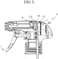
- FIG. 3 is a longitudinal sectional view showing the accumulator sprayer X in the state that the valve structure A moves upward.
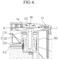
- FIG. 4 is an enlarged longitudinal sectional view showing the valve structure A in the state shown in FIG. 3 .
- valve piston portion 2 moves upward, the spring portion 1 contacts with the upper support portion C1 as shown in FIG. 4 . Furthermore, the valve piston portion 2 moves upward and the spring portion 1 deforms, thereby pressing force is applied against the valve piston portion 2.
- the valve structure A is formed of the inverted-dome-shaped spring portion 1 and the valve piston portion 2 drooping from the spring portion 1. Specifically, the cylindrical core rod portion 21 droops down from the approximately center of the spring portion 1, and an outer skirt portion 22 extending downward is formed continuously with the outer circumference of the core rod portion 21.
- a skirt portion extending downward longer than the outer skirt portion 22 is formed inside the outer skirt portion 22. That is, the core rod portion 21, the outer skirt portion 22 and the inner skirt portion 23 forms the valve piston portion 2.
- valve structure A is formed by the inverted-dome-shaped spring portion 1 and the valve piston portion 2 drooping from the spring portion 1, the resilient force of the spring portion 1 is applied evenly to the valve piston portion 2. Therefore, the pressing force caused by the spring portion 1 can be transmitted properly, the axial center of the valve piston portion 2 is stabilized, and lateral movement during vertical movement is prevented.
- Both the outer skirt portion 22 and the inner skirt portion 23 are formed in tapered shape, with their lower portion expanding outward.
- the outer skirt portion 22 performs the sealing function
- the inner skirt portion 23 serves as a valve body.
- the upper end of the core rod portion 21 is open and a center hole 1B is formed.
- the periphery of the opened center hole 1B is convex and forms a tubular protrusion 1A. That is, the center hole 1B and the tubular protrusion 1A are formed in approximately center of the spring portion 1.
- tubular protrusion 1A serves as a stopper of the valve structure A, which functions as a valve body.
- the valve structure A is attached to the sub-cylinder portion B2.
- the sub-cylinder portion B2 is formed in a cylindrical shape whose top is open, and the valve structure A is attached so that the outer skirt portion 22 and the inner skirt portion 23 press the inner wall of the sub-cylinder portion B2.
- the valve structure A is placed on the lower support portion B23 formed at the bottom portion of the sub-cylinder portion B2.
- the length L1 of the valve structure A in the unloaded state is longer than the wall portion of the sub-cylinder portion, and its upper end (i.e., the spring portion 1) is supported by the upper support portion C1 of the cover portion C.
- valve structure A is mounted in the sub-cylinder portion B2 so as not to contact with the upper support portion C1.
- the length L1 of the valve structure A in unloaded state and the shortest distance L2 between the lower support portion B23 and the upper support portion C1 satisfy the relation of L1 ⁇ L2. That is, in the initial set state, the valve structure A is mounted in the sub-cylinder portion B2 in the non-contact condition with the upper support portion C1.
- the upper support portion C1 of the cover portion C is a portion to which the spring portion 1 contacts in the inner wall of the cover portion C.
- a convex stopper portion C2 is provided at a position corresponding to the tubular protrusion 1A. The stopper portion C2 for restricting the upward movement of the valve structure A.
- valve structure A Since the valve structure A is even in circumferential direction in the top view, it can contact the upper support portion C1 of the cover portion C evenly and receive the reaction force equally.
- the spring portion 1 and the valve piston portion 2 are integrally formed.
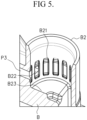
- FIG. 5 is a drawing to illustrate an inner circumferential wall of a sub-cylinder portion.
- a plurality of concave longitudinal groove portions B21 are provided extending vertically in all directions and at regular intervals.
- the through hole B22 contacting with the third passage portion P3 is provided at the bottom of the longitudinal groove portion B21 provided at the position corresponding to the third passage portion P3 located on the nozzle portion F side. No thorough holes B22 are provided in the vertical groove portions B21 other than those corresponding to the nozzle portion F.
- the inner wall functions as a pillar.
- the third passage portion P3 is provided at a certain distance from the bottom portion of the sub-cylinder portion B2. Specifically, it is provided at a height of 2 to 3 mm from the bottom portion.
- the liquid flows in the following order: the container J, the introduction tube H, the first passage portion P1, the first valve FV, the main cylinder portion B1, the second passage portion P2, the sub-cylinder portion B2, the vertical groove portion B21 (the through hole B22), the third passage portion P3 and the nozzle portion F, and is sprayed from the nozzle portion F to outside.
- the first valve FV and the second valve are closed, and the liquid is filled from the introduction tube H to the sub-cylinder portion B2.
- the trigger portion E is not rotated.
- the piston portion D moves in the main cylinder portion B1 in conjunction with the trigger portion E, and the pressure in the main cylinder portion B1 is increased (accumulated).
- the main cylinder portion B1 and the lower space of the valve piston portion 2 are connected via the second passage portion P2, and filled with the liquid.
- valve piston portion 2 moves upward as if pushed up by it, and the spring portion 1 is pressed and deformed (see FIG. 3 and FIG. 4 ).
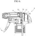
- FIG. 6 is a longitudinal sectional view showing an accumulator sprayer X in the state that the valve structure A comes up to an upper dead point.
- FIG. 7 is an enlarged longitudinal sectional view showing the valve structure A in the state shown in FIG. 6 .
- valve structure A comes up to the upper dead point and the deformation of the spring portion 1 is suppressed within a certain range. As a result, the load on the spring portion 1 can be reduced and bending deformation etc. of the spring portion 1 can be suppressed.
- the trigger portion E is returned to its initial position by the spring force of the trigger-returning spring I.
- the piston portion D moves in the main cylinder portion B1, resulting in negative pressure in the main cylinder portion B1 and opening the first valve FV.
- the second valve (the valve structure A) is in the closed state as described above.
- the accumulator sprayer X returns to the initial set state. At this time, both the first valve FV and the second valve are closed, and the liquid is filled from the introduction tube H to the sub-cylinder portion B2.
- PP resin polypropylene resin
- PP resin polyacetal resin
- POM resin polyacetal resin
- valve structure A is attached so as to contact with the lower support portion B23 and not to contact with the upper support portion C1, but the invention is not limited to this.
- the valve structure A may be attached so as to contact with only the upper support portion C1, to contact neither the upper support portion C1 nor the lower support portion B23.
- the spring portion 1 and the valve piston portion 2 in the valve structure A are circular in top view, but this invention is not limited to this, and any appropriate shape that allows the spring portion 1 to press down the valve piston portion 2 can be adopted.
- the spring portion 1 and the valve piston portion 2 are integrally formed, but may be provided separately.
- the accumulator sprayer X of the present invention can be widely used for spraying liquid by opening and closing of the first valve FV and the second valve, and by suppressing the deformation of the valve structure A, the function can be maintained for a long time and suitable spraying can be performed.
Landscapes
- Containers And Packaging Bodies Having A Special Means To Remove Contents (AREA)
- Closures For Containers (AREA)
Applications Claiming Priority (2)
| Application Number | Priority Date | Filing Date | Title |
|---|---|---|---|
| JP2022075601A JP2023164197A (ja) | 2022-04-29 | 2022-04-29 | 蓄圧式スプレイヤ |
| PCT/JP2023/016206 WO2023210611A1 (ja) | 2022-04-29 | 2023-04-25 | 蓄圧式スプレイヤ |
Publications (2)
| Publication Number | Publication Date |
|---|---|
| EP4516409A1 true EP4516409A1 (de) | 2025-03-05 |
| EP4516409A4 EP4516409A4 (de) | 2026-04-29 |
Family
ID=88519011
Family Applications (1)
| Application Number | Title | Priority Date | Filing Date |
|---|---|---|---|
| EP23796351.7A Pending EP4516409A4 (de) | 2022-04-29 | 2023-04-25 | Druckakkumulierende sprühvorrichtung |
Country Status (5)
| Country | Link |
|---|---|
| US (1) | US20250296105A1 (de) |
| EP (1) | EP4516409A4 (de) |
| JP (1) | JP2023164197A (de) |
| CN (1) | CN119095672A (de) |
| WO (1) | WO2023210611A1 (de) |
Family Cites Families (7)
| Publication number | Priority date | Publication date | Assignee | Title |
|---|---|---|---|---|
| JP3452283B2 (ja) * | 1995-01-30 | 2003-09-29 | 株式会社吉野工業所 | トリガー式噴霧器 |
| JPH1076196A (ja) * | 1996-09-04 | 1998-03-24 | Yoshino Kogyosho Co Ltd | 合成樹脂製スプリングとこれを用いた蓄圧式吐出弁 |
| JP2002011389A (ja) * | 2000-06-30 | 2002-01-15 | Yoshino Kogyosho Co Ltd | 蓄圧式噴霧器 |
| JP4628035B2 (ja) * | 2004-08-02 | 2011-02-09 | 久光製薬株式会社 | ポンプスプレー装置 |
| JP6057597B2 (ja) * | 2011-08-12 | 2017-01-11 | キャニヨン株式会社 | 蓄圧式トリガースプレイヤー及びその蓄圧バルブ |
| ITMI20112168A1 (it) * | 2011-11-28 | 2013-05-29 | Mwv Vicenza S P A | Spruzzatore per liquidi con camera di precompressione |
| JP2015044592A (ja) * | 2011-12-28 | 2015-03-12 | 多田 哲也 | プッシュ型ポンプディスペンサー及びそれに組み込まれる合体バルブ構造体 |
-
2022
- 2022-04-29 JP JP2022075601A patent/JP2023164197A/ja active Pending
-
2023
- 2023-04-25 WO PCT/JP2023/016206 patent/WO2023210611A1/ja not_active Ceased
- 2023-04-25 EP EP23796351.7A patent/EP4516409A4/de active Pending
- 2023-04-25 US US18/860,754 patent/US20250296105A1/en active Pending
- 2023-04-25 CN CN202380035926.1A patent/CN119095672A/zh active Pending
Also Published As
| Publication number | Publication date |
|---|---|
| US20250296105A1 (en) | 2025-09-25 |
| CN119095672A (zh) | 2024-12-06 |
| WO2023210611A1 (ja) | 2023-11-02 |
| EP4516409A4 (de) | 2026-04-29 |
| JP2023164197A (ja) | 2023-11-10 |
Similar Documents
| Publication | Publication Date | Title |
|---|---|---|
| EP0755305B1 (de) | Handbetätigte flüssigkeitshubkolbenpumpe | |
| US4511065A (en) | Manually actuated pump having pliant piston | |
| KR101590865B1 (ko) | 디스펜서 용기 | |
| EP4541465A1 (de) | Ventilstruktur und stausprüher mit der ventilstruktur | |
| IE50623B1 (en) | Leak proof dispensing pump | |
| KR20040057923A (ko) | 유동체저장용기 | |
| KR20030090534A (ko) | 액체분배용기 용 실린더 및 밸브 구조체 | |
| MXPA05005607A (es) | Bomba de precompresion de altura reducida. | |
| IT8448337A1 (it) | Pompa erogatrice atta al riempimento a pressione | |
| KR20210124889A (ko) | 액체 분사 펌프 | |
| US20070181611A1 (en) | Pump having a sealing mechanism | |
| EP3593908B1 (de) | Medikamentenspender zur vorbeugung der infiltration von bakterien | |
| EP4516409A1 (de) | Druckakkumulierende sprühvorrichtung | |
| CN113747978B (zh) | 排出头和具有排出头的液体分配器 | |
| JP6233680B2 (ja) | 逆止弁付きヒンジキャップ | |
| EP3228212A1 (de) | Dichtungsstruktur für einen behälter von kosmetik in cremeform | |
| JP2008260539A (ja) | ピストンおよびそのピストンを使用した流動体容器 | |
| JP5820690B2 (ja) | 吐出ポンプ | |
| JP2009173319A (ja) | ピストンおよびそのピストンを使用した流動体容器 | |
| KR102576233B1 (ko) | 화장품용기 | |
| KR20210124871A (ko) | 화장품 용기 | |
| JP2003128171A (ja) | ポンプユニット及び容器 | |
| JP7844318B2 (ja) | 吐出器 | |
| KR102556042B1 (ko) | 화장품용기 | |
| JP7837665B2 (ja) | 吐出具及び吐出容器 |
Legal Events
| Date | Code | Title | Description |
|---|---|---|---|
| STAA | Information on the status of an ep patent application or granted ep patent |
Free format text: STATUS: THE INTERNATIONAL PUBLICATION HAS BEEN MADE |
|
| PUAI | Public reference made under article 153(3) epc to a published international application that has entered the european phase |
Free format text: ORIGINAL CODE: 0009012 |
|
| STAA | Information on the status of an ep patent application or granted ep patent |
Free format text: STATUS: REQUEST FOR EXAMINATION WAS MADE |
|
| 17P | Request for examination filed |
Effective date: 20241017 |
|
| AK | Designated contracting states |
Kind code of ref document: A1 Designated state(s): AL AT BE BG CH CY CZ DE DK EE ES FI FR GB GR HR HU IE IS IT LI LT LU LV MC ME MK MT NL NO PL PT RO RS SE SI SK SM TR |
|
| DAV | Request for validation of the european patent (deleted) | ||
| DAX | Request for extension of the european patent (deleted) | ||
| REG | Reference to a national code |
Ref country code: DE Ref legal event code: R079 Free format text: PREVIOUS MAIN CLASS: B05B0011000000 Ipc: B05B0011100000 |