EP4512766A2 - Brandbekämpfungsvorrichtung - Google Patents
Brandbekämpfungsvorrichtung Download PDFInfo
- Publication number
- EP4512766A2 EP4512766A2 EP24214553.0A EP24214553A EP4512766A2 EP 4512766 A2 EP4512766 A2 EP 4512766A2 EP 24214553 A EP24214553 A EP 24214553A EP 4512766 A2 EP4512766 A2 EP 4512766A2
- Authority
- EP
- European Patent Office
- Prior art keywords
- fire fighting
- fighting device
- fluid
- wall
- hoist
- Prior art date
- Legal status (The legal status is an assumption and is not a legal conclusion. Google has not performed a legal analysis and makes no representation as to the accuracy of the status listed.)
- Pending
Links
Images





Classifications
-
- A—HUMAN NECESSITIES
- A62—LIFE-SAVING; FIRE-FIGHTING
- A62C—FIRE-FIGHTING
- A62C31/00—Delivery of fire-extinguishing material
- A62C31/02—Nozzles specially adapted for fire-extinguishing
- A62C31/22—Nozzles specially adapted for fire-extinguishing specially adapted for piercing walls, heaped materials, or the like
-
- A—HUMAN NECESSITIES
- A62—LIFE-SAVING; FIRE-FIGHTING
- A62C—FIRE-FIGHTING
- A62C31/00—Delivery of fire-extinguishing material
- A62C31/02—Nozzles specially adapted for fire-extinguishing
- A62C31/24—Nozzles specially adapted for fire-extinguishing attached to ladders, poles, towers, or other structures with or without rotary heads
-
- A—HUMAN NECESSITIES
- A62—LIFE-SAVING; FIRE-FIGHTING
- A62C—FIRE-FIGHTING
- A62C31/00—Delivery of fire-extinguishing material
- A62C31/28—Accessories for delivery devices, e.g. supports
-
- B—PERFORMING OPERATIONS; TRANSPORTING
- B65—CONVEYING; PACKING; STORING; HANDLING THIN OR FILAMENTARY MATERIAL
- B65D—CONTAINERS FOR STORAGE OR TRANSPORT OF ARTICLES OR MATERIALS, e.g. BAGS, BARRELS, BOTTLES, BOXES, CANS, CARTONS, CRATES, DRUMS, JARS, TANKS, HOPPERS, FORWARDING CONTAINERS; ACCESSORIES, CLOSURES, OR FITTINGS THEREFOR; PACKAGING ELEMENTS; PACKAGES
- B65D90/00—Component parts, details or accessories for large containers
-
- B—PERFORMING OPERATIONS; TRANSPORTING
- B65—CONVEYING; PACKING; STORING; HANDLING THIN OR FILAMENTARY MATERIAL
- B65D—CONTAINERS FOR STORAGE OR TRANSPORT OF ARTICLES OR MATERIALS, e.g. BAGS, BARRELS, BOTTLES, BOXES, CANS, CARTONS, CRATES, DRUMS, JARS, TANKS, HOPPERS, FORWARDING CONTAINERS; ACCESSORIES, CLOSURES, OR FITTINGS THEREFOR; PACKAGING ELEMENTS; PACKAGES
- B65D90/00—Component parts, details or accessories for large containers
- B65D90/54—Gates or closures
-
- B—PERFORMING OPERATIONS; TRANSPORTING
- B66—HOISTING; LIFTING; HAULING
- B66C—CRANES; LOAD-ENGAGING ELEMENTS OR DEVICES FOR CRANES, CAPSTANS, WINCHES, OR TACKLES
- B66C23/00—Cranes comprising essentially a beam, boom, or triangular structure acting as a cantilever and mounted for translatory of swinging movements in vertical or horizontal planes or a combination of such movements, e.g. jib-cranes, derricks, tower cranes
- B66C23/62—Constructional features or details
- B66C23/64—Jibs
- B66C23/70—Jibs constructed of sections adapted to be assembled to form jibs or various lengths
-
- B—PERFORMING OPERATIONS; TRANSPORTING
- B66—HOISTING; LIFTING; HAULING
- B66F—HOISTING, LIFTING, HAULING OR PUSHING, NOT OTHERWISE PROVIDED FOR, e.g. DEVICES WHICH APPLY A LIFTING OR PUSHING FORCE DIRECTLY TO THE SURFACE OF A LOAD
- B66F11/00—Lifting devices specially adapted for particular uses not otherwise provided for
-
- B—PERFORMING OPERATIONS; TRANSPORTING
- B66—HOISTING; LIFTING; HAULING
- B66F—HOISTING, LIFTING, HAULING OR PUSHING, NOT OTHERWISE PROVIDED FOR, e.g. DEVICES WHICH APPLY A LIFTING OR PUSHING FORCE DIRECTLY TO THE SURFACE OF A LOAD
- B66F11/00—Lifting devices specially adapted for particular uses not otherwise provided for
- B66F11/04—Lifting devices specially adapted for particular uses not otherwise provided for for movable platforms or cabins, e.g. on vehicles, permitting workmen to place themselves in any desired position for carrying out required operations
- B66F11/042—Lifting devices specially adapted for particular uses not otherwise provided for for movable platforms or cabins, e.g. on vehicles, permitting workmen to place themselves in any desired position for carrying out required operations actuated by lazy-tongs mechanisms or articulated levers
Definitions
- the present invention relates to a fire fighting device with a fire fighting aggregate for penetrating a wall and injecting fire fighting fluid into a space behind the wall, said fire fighting aggregate comprising a fluid driven rotating motor, such as a turbine, having a rotor rotating around an axis of rotation defining an axial direction, a rotating cutting element attached to the rotor to be rotated thereby, a fluid inlet for receiving fire fighting fluid from a source of fire fighting fluid, and a first conduit for feeding the fire fighting fluid from the fluid inlet to the rotor to drive the fluid driven rotating motor.
- a fluid driven rotating motor such as a turbine
- FR 2854576 A1 discloses a fire fighting device of the above kind in which the fluid driven rotating motor is a turbine.
- the device is attached to the end or nozzle of a fire hose whereby it is possible manually to cut a hole in a wall by means of the rotating cutting element and subsequently to spray fire fighting fluid (water) into the hole and into the space behind the wall since a central axial passage is provided through the device and the fluid or water leaving the turbine exits in part on a radius smaller than the radius of the hole.
- US 4 271 909 discloses another device comprising the feature mentioned by way of introduction and provided for manual operation.
- US 2005/0252989 disclose another device used for fighting fires in for example rooms, attics and the like.
- the device is provided with a water driven auger and a spray nozzle arranged for rotation relative to a housing.
- the firefighter places the tip of the auger against the surface or separation which it is desirable to penetrate in order for the nozzle to reach the fire.
- a handle is provided which the firefighter uses to control and force the tip of the auger against the surface.
- the device will drill itself through the separation, and water issuing from the spray nozzle will quell or dampen the fire.
- the device may be fastened to the surface, and be operated and controlled remotely.
- CZ2011-170 relates to an extinguishing and penetration unit in which a drilling unit (22) is connected with a spraying head (1) provided with a drilling and centering pin (2) being coupled through the mediation of a freewheeling clutch (5) by one end of an internal hollow shaft (3), whereby the other end of the internal hollow shaft (3) is provided with a rotary supply (8) of extinguishing water.
- the internal hollow shaft (3) of the drilling and centering pin (2) is supported by a pair (6) radial antifriction bearings and one axial antifriction bearing (7) being all mounted by their outer surfaces within an external hollow shaft (9).
- One side of the internal hollow shaft (3) is fixedly coupled with a pin toothed wheel (16) which engages with a first section (4) of the pin hydraulic motors, which section is fixedly coupled through the mediation of a cage (21) with the frame (19).
- the toothed wheel (17) of the boring crown engages with the second section (18) of the crown rotary hydraulic motors, which are fixedly coupled through the mediation of the cage (21) with the frame (19).
- the object of the present invention is to provide a fire fighting device which need not be held by an operator during operation.
- a device as mentioned by introduction which comprises a support for attachment to the wall, wherein the fire fighting aggregate is suspended by said support, at least the rotating cutting element being movable relative to the support towards the wall, a power means is provided for pressing the rotating cutting element towards the wall, and a second conduit is provided for feeding the fire fighting fluid to the power means to provide for said power means to press the rotating cutting element towards the wall.
- the fire fighting device may be brought into position, e.g. by means of a hoist of any kind, with e.g. a fire hose connected to the fluid inlet and be attached to the wall, whereafter the device automatically cuts hole in the wall. Further it is obtained that a hole may be cut for introduction of fire fighting fluid into a space behind a wall without the need for any other energy source than the pressurised fire fighting fluid.
- the fire fighting fluid may be water and the source of fire fighting fluid may be a fire hydrant. Accordingly, the fire fighting device may comprise a connector for connecting a fire hose to the device.
- the support When attaching for use of the fire fighting device the support to wall to be penetrated, the support may in an embodiment of the invention be fastened directly to the wall or it may be fastened to a rigid structure fixed relative to the wall or attached to the wall, said structure preferably having a distance from the wall less than 1 meter, preferably less than 50 cm, and especially within 10 cm or within 5 cm from the wall.
- the direction of the movement of the rotary cutting element towards the wall may be generally parallel or co-axial with the axial direction.
- the fluid driven rotating motor comprises a stator attached to the support, the rotor being seated for rotation on said stator, the rotor comprises a driving part and a driven part the driving part driving rotary the driven part, wherein the rotary cutting element is attached to the driven part.
- stator attached to the support
- the rotor comprises a driving part and a driven part the driving part driving rotary the driven part, wherein the rotary cutting element is attached to the driven part.
- the driven part is displaceable in the axial direction from a retracted position to an extended position together with the rotating cutting element and comprises a surface element constituting part of the power means, said surface element being subject to a pressure of the fire fighting fluid through the second conduit to press the rotating cutting element towards the wall.
- stator and the driven part between them define an annular chamber receiving fire fighting fluid through the second conduit, said annular chamber being defined by a first external cylindrical surface of the stator, a first internal cylindrical surface of the driven part, an annular surface of the stator adjacent to the first external cylindrical surface, and said surface element constituted by an annular surface part of the driven part adjacent to the first internal cylindrical surface.
- annular chamber provides the power means generally in the form of a power cylinder.
- the second conduit extends through the stator and out through at least one first aperture in the first external cylindrical surface.
- fluid pressure is provided for the annular chamber.
- At least one nozzle opening at the rotating cutting element is provided for ejecting fire fighting fluid, and an adjustable valve adjustable between an open position and a closed position is provided, whereby the adjustable valve in the closed position at least throttles a flow of fire fighting fluid to said nozzle opening.
- the driven part comprise an end comprising a cylindrical end chamber extending from said annular surface part, said cylindrical end chamber accommodating an end of the stator comprising at least a part of the first external cylindrical surface, when the driven part is in the retracted position, said end part of the stator being out of the cylindrical end chamber when the driven part is in the extended position, said first external cylindrical surface fitting slidably in said cylindrical end chamber, and wherein said cylindrical end chamber comprises a fluid outlet.
- a fluid outlet may flow freely to the fluid outlet when the end part of the stator being out of the cylindrical end chamber, while flow of the fluid towards the fluid outlet is at least restricted when the end part of the stator is inserted in the cylindrical end chamber.
- the rotating cutting element is attached co-axially to the driven part and at least one passage is provided to receive fire fighting fluid from the fluid outlet for said fire fighting fluid to be ejected into a hole cut by the rotating cutting element.
- the device to eject fire fighting fluid into the space behind the wall once the hole has been cut.
- the stator comprises an annular protrusion with a second external cylindrical surface in sliding engagement with said first internal cylindrical surface, said annular protrusion comprising at one axial end said annular surface, said annular protrusion comprising at an opposite axial end a second annular surface, a third annular surface positioned opposite the second annular surface being connected to the first internal cylindrical surface, a second annular chamber thereby being provided between the second annular surface and the third annular surface, whereby either the area of the second annular surface part, and thus of the annular surface part of the driven part, is bigger than the area of the third annular surface as seen in the axial direction, or the second annular chamber is vented to the surroundings.
- the third annual surface may abut on the second annular surface when the driven part is in the extended position thus defining said extended position.
- the driving part comprises a hollow shaft member, a number of nozzles extending from the hollow shaft member to eject fire fighting fluid fed to the rotor, the nozzles thereby ejecting the fire fighting fluid in a direction with a circumferential component in a plane perpendicular to the axial direction.
- the driving part is driven rotationally in a direction opposite to said circumferential component.
- the fluid driven rotating motor is provided generally in the form of a so-called Segner wheel or Segner turbine.
- the stator comprises a circular cylindrical section which has a third external cylindrical surface and the driving part has a second internal cylindrical surface in sliding engagement with said third external cylindrical surface
- the first conduit extends through the stator and out through at least one second aperture in the circular cylindrical section at the third external cylindrical surface at an axial position
- the driving part at the second internal cylindrical surface comprises at least one third aperture for receiving fire fighting fluid from the first conduit
- a circumferential recess defining an axial recess area is provided in one of the third external cylindrical surface and the second internal cylindrical surface
- the second aperture and the third aperture are opening into said circumferential recess when the driving part is in an axial starting position relative to the stator.
- an adjustable valve is attached to the first conduit, said adjustable valve being adjustable between an open position and a closed position, whereby the adjustable valve in the closed position at least throttles a flow of fire fighting fluid to the rotor.
- the driving part is displaceable in the axial direction relative to the stator from the axial starting position, which is a retracted position, to an extended position, whereby one of the second aperture and the third aperture is outside the axial recess area when the driving part is in the extended position.
- an adjustable valve opening and at least restricting the flow of fire fighting fluid to the rotor since said flow is at least restricted when one of the second and the third apertures are out of the axial recess area.
- the driving part and the driven part are integrated.
- the driving part and the driven part move in unison in the axial direction.
- stator is attached immovably to the support and the support is preferably rigid.
- the support is provided with means for attachment to the wall, said means comprising one or more of: a magnet, a suction device, a hook, a claw, a pair of jaws, a clamp, etc.
- the attachment means may be adapted to the intended place of use of a specific fire fighting device according to the invention, e.g. on a ship container made of ferromagnetic steel and/or wherein bars are permanently mounted adjacent to a wall or door of the container, on a wall with a smooth surface, on a surface with protrusions adapted for engagement with hooks, claws, clamps, a pair of jaws, etc.
- the stator will be fixed relative to the wall during use, when the support is rigid and the stator is attached immovably to the support.
- the hoist provides a number of advantages. Often, particularly with ISO containers being carried on freighters, they are stabled to a height where it is not possible for personnel to immediately reach the desired height.
- the hoist may be extended be extending the telescopic section such that the fastening bar is positioned at a desired height relative to the container in which it is desirable to extinguish the fire.
- the fastening bar is typically arranged perpendicular to the longitudinal extent of the telescopic section. In this manner it is possible to insert the fastening bar between the front of the container and the vertical bars which are typically part of the locking arrangement on ISO containers (see figure 6 ).
- the fire fighting device When the telescopic section including the fastening bar is installed against the surface on which it is desirable to place the fire fighting device, the fire fighting device is attached to the wire and hoisted up to the upper end of the telescopic section such that the fire fighting device will be positioned immediately adjacent the fastening bar and thereby in its operational position.
- the hoist is in a further advantageous embodiment provided with a winch at the lower end such that it is possible to activate the winch in order to elevate the fire fighting device to the desired elevation.
- the winch may be manually or electrically operated.
- the two or more concentric sections may be extended by applying a force to the lower ends of each section, where said force is generated by one or more of the following: electrical motor means, hydraulic or hydro means, pneumatic means, mechanical means in the shape of a winch, releasable gas springs.
- the concentric sections may be extended to a relatively high elevation, for example 15-20 meters, it may become difficult to handle this extension by hand. Therefore, by providing a force to extend the concentric sections this work is eased.
- the force may be generated by electrical motor means which in addition to being a well-known technology is easy to install, easy to handle and furthermore electricity is present on most ships, and as such the source of energy is readily available.
- electrical motor means which in addition to being a well-known technology is easy to install, easy to handle and furthermore electricity is present on most ships, and as such the source of energy is readily available.
- the alternatives, for example using hydraulic or hydro means, are also viable in that for example ships carrying containers will have a hydraulic system for other reasons and as such it is possible to hook up to the existing hydraulic system and thereby convert the hydraulic system to the force necessary to extend the concentric sections.
- a fire fighting liquid which is typically water
- water is available anyway in connection with the hoist when used together with a fire fighting device and as such by diverting part of the water pressure to be used as the force extending the concentric sections is a straightforward and available solution.
- hydraulic means most ships of the type carrying containers will also have pneumatic installations such that it is possible divert a pressurized hose, for example with pressurized air, to the concentric sections and thereby elevate the concentric sections by supplying the force by means of air.
- a winch in some embodiments may be installed in order to elevate the fire fighting device to the upper end of the hoist the same winch or an additional winch may be used in order to provide the force pushing up the concentric sections.
- the hoist may in a further advantageous embodiment be provided adjacent the upper end of the hoist with a releasable locking mechanism where said locking mechanism is suitable to interact and lock the fire fighting device in position adjacent the upper end of the hoist.
- the locking means may for example be a spring loaded tab which as the fire fighting device passes the place where the tab is present pushed the tab into the hoist, and as the fire fighting devise passes the tab, an aperture in the fire fighting device may release the spring force, whereby the tab is inserted into the aperture such that the fire fighting device is locked relative to the hoist.
- the underside of the fire fighting device will also release the tab such that the fire fighting device may be resting on the tab.
- internal means for example in shape of a wire threaded pulley, and operational from the lower end of the hoist, may be used in order to release the locking mechanism.
- Another alternative locking mechanism may be a pivotable member which may pivot out of the perimeter of the hoist as the fire fighting device has passed and thereby creating a lock such that the fire fighting device cannot slide back down the hoist.
- the fire fighting device is elevated slightly, or the hoist is lowered slightly relative to the fire fighting device which due to the engagement with the fastening bar to the side of the container is locked in place allowing the hoist to be lowered such that the releasable locking mechanism in the shape of a pivotal member may be pivoted back inside the perimeter of the hoist whereby it is possible to lower the fire fighting device along the hoist.
- the invention is also directed at a method of using a fire fighting device as discussed above in order to quell a fire in an object at an elevated position where a hoist as also discussed above is used in order to elevate the fire fighting device to the desired position in which it is desirable to apply the fire fighting device against the object.
- This method comprises the following steps:
- the fire fighting device together with the hoist constitutes a very effective overall fire fighting device regardless of the height where the object is positioned such that it is possible to position the effective fire fighting device manually and relatively easily at a desired elevation.
- the figures show an embodiment of a fire fighting device which comprises a support 1 and a fire fighting aggregate 3.
- the fire fighting device is attached to a wall 5 which is to be penetrated for ejecting a fire fighting fluid into a space behind the wall.
- front end the end of the device, or parts thereof, closest to the wall 5 during use is designated “front end” and the opposite end is designated “rear end”.
- rear end the opposite end is designated “forward”
- forward designates a direction from the rear end towards the front end and “rearward” designates the direction opposite to "forward”, etc.
- a wall should be interpreted as any flat element defining a space into which water should be sprayed to fight a fire, thus including e.g. a door, a roof, a floor, etc.
- the support 1 comprises a number of legs 101 provided with feet 103 for abutment against the wall 5 to position the fire fighting device.
- the support is provided with means for attachment to the wall said means being in the present embodiment permanent magnets 105 attached to the feet 103 since the fire fighting device in the present embodiment is intended for use in fighting fires in steel containers e.g. on board a container ship.
- the support 1 further comprises a tubular connector 107 with an internal thread for receiving a threaded end of a stator 301 of the fire fighting aggregate 3.
- the tubular connector 107 is in the present embodiment provided with a fire hose connector 109 for connecting a fire hose 110 (see Fig. 7 ), the fire hose connector 109 thus providing a fluid inlet of the fire fighting device.
- legs 101 of the support 1 are shown it should be understood that the support 1 in practise comprise a number of legs that will provide for a stable attachment of the device to the wall.
- the fire fighting aggregate 3 comprises, apart from said stator 301, a rotor 303 and a rotating cutting element 305 all three of which are aligned on an axis of rotation 307 of the rotor 303.
- the rotating cutting element 305 is rotating coaxially with the rotor 303.
- the rotating cutting element 305 is shown to be a hole saw, but any device might be use provided that is suitable for trepanning or drilling a hole of a certain diameter in the material of a wall for which the fire fighting device might be intended to be used.
- the rotor 303 comprises a driving part 310 and a driven part 320.
- the driving part 310 and the driven part 320 are integrated and accordingly they move in unison both in rotation around the axis of rotation 307 and in translation along said axis.
- the stator 301 is a generally tubular body and is as mentioned above threaded i.e. at its rear end and is through the thread 302 connected to the tubular connector 107.
- the stator 301 is attached to the support 1 to be immovable relative to the wall 5 during operation.
- the stator 301 comprises three circular cylindrical sections, which counted from the front end are designated first, second and third circular cylindrical section, respectively.
- the stator 301 At its front end the stator 301 has a closed end wall.
- apertures providing passages from an inner hollow of the tubular body to the outside are provided in the circular cylindrical sections as will be explained in the following.
- the threaded rear end of the stator 301 is open to receive water supplied through a fire hose connected to the fire hose connector 109. Accordingly, the inner hollow of the tubular body of the stator 301 provides part of several conduits for feeding the water to various places in the device, i.e. a first conduit for feeding the driving part 310 and a second conduit for feeding the driven part 320, as it will be explained further below.
- the rotor 303 including, in the present embodiment, the driving part 310 and the driven part 320, comprises a likewise generally tubular body which is seated for rotation on the tubular body of the stator 301.
- the driven part 320 comprises a first internal cylindrical surface 321 and an annular surface part 322 adjacent to the first internal cylindrical surface 321.
- the first circular cylindrical section of the stator 301 comprises a first external cylindrical surface 331.
- the extent of the second circular section is defined by an annular protrusion 332 which has a second external cylindrical surface 333.
- the second external surface 333 thus has a larger diameter than the first external surface 331.
- At a front end of the annular protrusion 332 the latter has an annular surface 334.
- first apertures 341 are spaced equidistantly around the first external cylindrical surface 331 to provide an opening between the inner hollow of the stator 301 and the annular chamber 340.
- the fire hose connector 109, the tubular connector 107, the inner hollow of the stator 301 and the first apertures 341 together provide what is arbitrarily designated the second conduit.
- a front end of the driven part 320 comprises in the present embodiment a generally cup shaped plug member 342 which by means of an external thread 342a is threaded into an internal thread provided in axial extension of the first internal cylindrical surface 321.
- the cup shaped plug member 342 provides by a rim of the cup shape the annular surface part 322 at its rear end, and at its front end it comprises co-axially with the axis of rotation 307 a threaded tubular protrusion 343 onto which the rotating cutting element 305 is threaded.
- the cup shaped plug member 342 provides, extending from the rim, a cylindrical end chamber 344 of the driven part 320.
- the cylindrical end chamber 344 accommodates an end part of the stator 301 comprising at least a part of the first external cylindrical surface 331, when the driven part is in the axial starting position, which is a retracted position, as it will be explained below.
- An inner hollow of the tubular protrusion 343 is extended through a bottom part of the cup shaped plug member 342 to provide a fluid outlet 345 allowing water in the cylindrical end chamber 344 to flow out of said chamber, and the inner hollow of the tubular protrusion 343 per se provides a passage for fire fighting fluid such as water to receive water from the fluid outlet 345 for said water to be ejected into a hole cut by the rotating cutting element, as it will be further explained below.
- Further outlet openings 345a are provided around the tubular protrusion 343 through the bottom part of the cup shaped plug member 342 and through corresponding openings in the rotating cutting element 305 (not shown).
- the first external cylindrical surface 331 is fitting slidably in the cylindrical end chamber 344 and the first internal cylindrical surface 321 is fitting slidably on the second external cylindrical surface 333. Accordingly, the driven part 320 may slide on the stator 301 in rotation around the axis of rotation 307 as well in translation along said axis, as it will be explained further below with reference to the function of the fire fighting device.
- the driving part 310 comprises a hollow shaft member 311 which comprises a second internal cylindrical surface 312 which is fitting slidable on a third external cylindrical surface 313 of the third circular cylindrical section of the stator 301.
- the first conduit for feeding the driving part 310 extends through the fire hose connector 109, the tubular connector 107, the stator 301 and out through at least one, in the present embodiment six or eight, second apertures 314 in the third circular cylindrical section at the third external cylindrical surface 313 at an axial position.
- the driving part 310 comprises at least one third aperture 315 for receiving water from the first conduit.
- a circumferential recess 316 defining an axial recess area is provided in the second internal cylindrical surface 312 and the second apertures 314 are opening into said recess 316, and the third apertures 315 are also opening into said circumferential recess 316 when the driving part 310 is in an axial starting position relative to the stator 301.
- a number of nozzles 317 are extending from the hollow shaft member 311 to eject the water fed through the first conduit to the rotor 303.
- the nozzles 317 receive the water through the third apertures 315, and the nozzles 317 are ejecting the water in a direction with a circumferential component in a plane perpendicular to the axis of rotation 307.
- the nozzles 317 are in the present embodiment provided by channels in a nozzle ring 318 shown in section in Fig. 5
- the driving part 310 is displaceable in the axial direction relative to the stator 301 from the axial starting position, which is a retracted position, to an extended position, whereby the second apertures 314 are outside the axial recess area defined by the recess 316, when the driving part 310 is in its extended position as seen in Figs. 2 and 4 .
- the driving part 310 and the driven part 320 are in the present embodiment integrated and accordingly move in unison, the driving part 310 and the driven part 320 will be in their respective retracted positions and extended positions simultaneously, the axial position of driving part 310 being controlled by the axial position of the driven part 320.
- the fire fighting device works as follows: A fire hose is connected to the fire hose connector 109 and the fire fighting device is attached to a wall 5 which should be penetrated for water or another fire fighting fluid to be ejected through the wall 5 into a space behind the wall.
- the rotor 303 including the driving part 310 and the driven part 320, will at this time be pushed to its axial starting position i.e. the retracted position shown in Fig. 1 .
- the water supply is turned on to supply water at a pressure of e.g. 2 to 10 bar to the fire fighting device.
- the water enters the fire fighting device through the fire hose connector 109 and the tubular connector 107 to follow the first and second conduit into the inner hollow of the stator 301 and out the second apertures 314 following the first conduit and also out through the first apertures 341 following the second conduit.
- the water flowing out through the first apertures 341 fills the first annular chamber 340 and water flowing out through the second apertures 314 fills the circumferential recess 316.
- the water is restricted but not prevented from flowing past said surfaces.
- a film of water with a thickness of e.g. 0.01-0.04 mm will be present between the respective surfaces fitting slidably with each other to provide a lubricating film facilitating movement of the rotor 303 relative to the stator 301. Further the water will flow into the second annular chamber 352.
- the water is restricted from flowing between the first external cylindrical surface 331 and the cylindrical wall of the cylindrical end chamber 344 and into said cylindrical end chamber 344. Accordingly, the water will build up pressure in the first annular chamber 340.
- the water in the circumferential recess 316 flows freely through the third apertures 315 and the nozzles 317 to be ejected by said nozzles 317 in directions 317a with a circumferential component in a plane perpendicular to the axis of rotation 307.
- This ejection of water will result in the rotor 303 being driven to rotate in an opposite direction of rotation 319 as it will be understood by the person skilled in the art, and the rotating cutting element 305 will thereby be driven to rotate likewise.
- the annular surface part 322 constitutes a surface element constituting part of a power means or a power cylinder.
- the pressure in the circumferential recess 316 is relatively low since the water flows freely out the nozzles 317 and accordingly the pressure in the second annular chamber 352 may appear to be smaller than the pressure in the first annular chamber 340.
- the rotating cutting element 305 cuts its way through the wall 5 and accordingly the rotor 303 is axially displaced in what has been defined as the forward direction.
- the fire fighting device should be dimensioned relative to the thickness of walls which the device is meant to penetrate so that, before the forward end of the stator 301 is completely withdrawn from the cylindrical end chamber 344, the rotating cutting element 305 has cut through the wall 5 allowing the rotor 303 to slide axially with only little resistance to the extended end position shown in Fig. 2 . In this extended end position, the third annular surface 351 abuts on the second annular surface 350 thereby defining the extended end position.
- a fire fighting device as described above including feet 103 with permanent magnets 105 may be attached directly to a surface of one of the doors 502 the permanent magnets 105 cohering to the door 502.
- the support 1 may be provided with other means for attachment to the wall 5, such means alternatively comprising one suction devices, which might provide for attachment directly to the surface of the wall 5 or door 502 or such means for attachment might comprise one or more hooks, claws, pairs of jaws, or clamps, which might be attached to one or more of the bars 503.
- the horizontal bar 403 is simply inserted between the two bars 503 and into one of the grooves 504 whereafter the fire fighting aggregate 3 and the support 1' are shifted laterally in a longitudinal direction of the groove 504 until the vertical bar 402 abuts one of the bars 503 as shown in Fig. 7 .
- the engagement of the horizontal bar 403 with a lower side wall 505 of the groove 504 and with the bar 503 and the engagement of the lower end of the vertical bar 402 with the main surface of the door 502 will keep the fire fighting aggregate 3 securely in place during operation. It is seen that the horizontal bar 403, though straight, functions as a hook hooking behind the bar 503.
- the vertical bar 402 might be constructed differently from what is shown in Fig. 7 as long as the support 1' comprises an element extending vertically (in the use position) to be fixed to the horizontal bar, to be able to abut on a surface below the groove 504, and to allow the rotating cutting element 305 to pass to the surface of the wall to be penetrated.
- the device may be attached directly to the wall to be penetrated of to a structure which is in a fixed position relative to the wall, preferably within a distance of 1 meter from the wall and especially within 10 cm or within 5 cm.
- the bars 503 and groove 504 illustrated in figures 6 and 7 are typically part of a door construction of a typical ship's container.
- the invention although not limited to use with containers and in particular the type of containers being used very widely for sea transport the following examples will be discussed with reference to a construction similar to the construction illustrated in figure 7 containing substantially vertical bars 503 and a substantially horizontal groove 504.
- FIG 8A and 8B is illustrated a further way of attaching the support to the wall to be penetrated.
- a variant of the support 1" is connected to the device 3 where the tubular connector 107 is connected to the firehose 110.
- the device is furthermore provided with a vertical bar 607 such that when the vertical bar 607 is placed parallel to one of the bars 503 and a water pressure is activated the piston 605, 606 will be activated thereby urging the piston 605 or 606 against the vertical bar 503. At some point the vertical bar 503 will come into contact with the vertical bar 607 and the piston 605 or 606 will effectively squeeze the bar 503 such that a firm grip is provided for the cutting device 3.
- the pistons 605, 606 will be able to move backwards thereby releasing its grip on the vertical bar 503 such that the device may be removed from the vertical bar 503.
- FIG 9 A further way of attaching the device to the wall is illustrated in figure 9 .
- the support 1 is again provided as a water conduit.
- the water connection is created in the tubular connector 107 such that water from the firehose may be led into the support 1'.
- the end of the pistons 704, 704' are provided with an oblique surface 705 such that the pistons 704, 704' will be wedged between the vertical bars 503 and the wall 502. In this manner the device is firmly fixed to the wall.
- the opening is large enough to accommodate a vertical bar 503 such that as illustrated with reference to figures 10B and 10C the section 803 may be fitted around the bar 503 and by tilting the bar as illustrated in figure 10C the bar 503 will become locked inside the cut-out 804 due to the geometric shape of the cut-out.
- FIG. 11 A further manner in which to attach the device to a vertical bar 503 is illustrated with reference to figure 11 .
- the device 3 and the support 1 is mounted on a first sliding bar 810.
- an aperture 811 is provided such that the drill 305 can operate through the aperture 811.
- the first slide bar 810 is connected to a second slide bar 812 by pivotable connectors 813.
- the distance will change due to the length of the connectors 813 such that in one position the slide bars 810, 812 will be firmly engaged with the vertical bar 503 such that the drilling action may commence at the desired height.
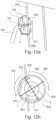
- the device 3 as illustrated with reference to figure 12A and 12B is mounted on a wheel 820.
- the device 3 and the tubular connector 106 are connected by four supports to the wheel, but any suitable number of supports may be provided.
- the wheel is provided with engagement sections 821, 822 which engagement sections 821, 822 are provided with wedge shaped engagement ends 123.
- FIG 13 is schematically illustrated the situation onboard a container ship where stacks of ISO containers 900 are arranged. In between the rows of ISO containers 900 is provided a division 901. The division will typically rise from the bottom of the hull 902 to a certain elevation, for example even with the railing of the ship. In this example 12 ISO containers are stacked one on top of the other, but in practice more or less containers may be stacked in this manner. In this situation a fire has been detected in one of the uppermost ISO containers 910 and a fire fighter 911 has erected the hoist 920 and fastened the hoist by means of the fastening bar (see figure 15 and 16 ). In the illustrated example the fire fighter 911 is in the process of hoisting the fire fighting device 3 connected to a fire hose 110.
- FIG 14 a similar scenario is illustrated, however, in this scenario the fire fighter 911 is elevated relative to the separation 901 by means of a lift 912. Instead of the lift it could be a scaffold, ladder or other means suitable for the task. In this manner it is possible to reach containers even further up or to avoid extending the hoist 920 to its full extent.
- the fire fighting device 3 has been installed at the intended location 903, and consequently the fire fighting may commence.
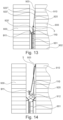
- FIG. 15 two different means of retaining the fire fighting device 3 adjacent the upper end of the hoist device 920 are illustrated.
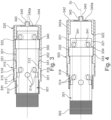
- the hoist device 920 comprises a number of sections, in the embodiments illustrated in figure 13 three sections 920', 920", 920"'. These extendable sections 920', 920", 920′′′ are concentrically arranged such that they may be extended as illustrated in figures 13 and 14 .
- a pulley wheel 921 In an uppermost end of the telescopic device is provided a pulley wheel 921.
- a wire is provided from the bottom of the hoist 920 around the pulley wheel and back initially to the bottom of the hoist. It is naturally clear that although a pully wheel is illustrated and suitable means for creating a low friction turning of the wire may be used, for example, blocks, low friction surface on a stainless steel bar or the like.
- wire shall be understood as any suitable type of flexible elongated member.
- a stainless steel wire is preferred but also ropes made from various base materials, such as for example carbon fibres, glass fibres and the like is contemplated within the term wire.
- This mechanism comprises a pivotable member 927 which may be moved slightly in the longitudinal direction of the hoist 920 due to a pin 928 travelling in an elongated slut provided in the upper end of the hoist 920.
- the flange 930 will again engage the fire fighting device whereby the pivotable member 927 will be pivoted out of the way allowing the fire fighting device to be lowered.
- the hoist comprises three sections, but in reality any suitable number of sections may be provided such that the hoist can elevate the fire fighting device to any desired height.
- the fire fighting device 3 is only elevated into the desired elevation once the fastening member of the hoist has been correctly positioned at its elevated position it is possible to operate the invention with very high telescopic members.
- the telescopic members may be 15-20 meters such that after for example having engaged the fastening member 932 in a groove 504 in a ISO container at a height of 15 meters it is very simple to elevate the fire fighting device into the correct operational position as discussed above.
Landscapes
- Health & Medical Sciences (AREA)
- Public Health (AREA)
- Business, Economics & Management (AREA)
- Emergency Management (AREA)
- Engineering & Computer Science (AREA)
- Mechanical Engineering (AREA)
- Structural Engineering (AREA)
- Life Sciences & Earth Sciences (AREA)
- Geology (AREA)
- Fire-Extinguishing By Fire Departments, And Fire-Extinguishing Equipment And Control Thereof (AREA)
- Nozzles (AREA)
Applications Claiming Priority (4)
| Application Number | Priority Date | Filing Date | Title |
|---|---|---|---|
| EP16199101.3A EP3323472A1 (de) | 2016-11-16 | 2016-11-16 | Brandbekämpfungsvorrichtung |
| EP17192104 | 2017-09-20 | ||
| EP17800384.4A EP3541480B1 (de) | 2016-11-16 | 2017-11-16 | Brandbekämpfungsvorrichtung |
| PCT/DK2017/050378 WO2018091055A1 (en) | 2016-11-16 | 2017-11-16 | Fire fighting device |
Related Parent Applications (2)
| Application Number | Title | Priority Date | Filing Date |
|---|---|---|---|
| EP17800384.4A Division EP3541480B1 (de) | 2016-11-16 | 2017-11-16 | Brandbekämpfungsvorrichtung |
| EP17800384.4A Division-Into EP3541480B1 (de) | 2016-11-16 | 2017-11-16 | Brandbekämpfungsvorrichtung |
Publications (2)
| Publication Number | Publication Date |
|---|---|
| EP4512766A2 true EP4512766A2 (de) | 2025-02-26 |
| EP4512766A3 EP4512766A3 (de) | 2025-05-14 |
Family
ID=60381993
Family Applications (2)
| Application Number | Title | Priority Date | Filing Date |
|---|---|---|---|
| EP17800384.4A Active EP3541480B1 (de) | 2016-11-16 | 2017-11-16 | Brandbekämpfungsvorrichtung |
| EP24214553.0A Pending EP4512766A3 (de) | 2016-11-16 | 2017-11-16 | Brandbekämpfungsvorrichtung |
Family Applications Before (1)
| Application Number | Title | Priority Date | Filing Date |
|---|---|---|---|
| EP17800384.4A Active EP3541480B1 (de) | 2016-11-16 | 2017-11-16 | Brandbekämpfungsvorrichtung |
Country Status (5)
| Country | Link |
|---|---|
| US (1) | US11395933B2 (de) |
| EP (2) | EP3541480B1 (de) |
| CN (2) | CN110022946B (de) |
| HR (1) | HRP20250256T1 (de) |
| WO (1) | WO2018091055A1 (de) |
Families Citing this family (15)
| Publication number | Priority date | Publication date | Assignee | Title |
|---|---|---|---|---|
| EP3541480B1 (de) * | 2016-11-16 | 2025-01-01 | Viking Life-Saving Equipment A/S | Brandbekämpfungsvorrichtung |
| TWI673084B (zh) * | 2018-10-05 | 2019-10-01 | National Formosa University | 多功能自動破窗滅火設備 |
| US12427349B1 (en) * | 2019-05-30 | 2025-09-30 | The United States Of America, As Represented By The Secretary Of The Navy | Hole saw breaching firefighting nozzle |
| DE102019125685B4 (de) * | 2019-09-24 | 2021-08-12 | PUTZ INNOVA GmbH | Bohrlöschgerät und Bohrlöschsystem |
| CN112206435A (zh) * | 2020-10-14 | 2021-01-12 | 四川恒远信友环境科技有限公司 | 一种适用于换流站Box-in的吸隔声安全装置 |
| CN112274811B (zh) * | 2020-10-29 | 2021-12-10 | 刘亮亮 | 一种城市高层楼房精准灭火消防机构 |
| CN112546490A (zh) * | 2020-11-30 | 2021-03-26 | 长沙中联消防机械有限公司 | 应急灭火系统和消防设备 |
| CN113484715B (zh) * | 2021-09-08 | 2021-11-05 | 南通国为半导体科技有限公司 | 半导体自动化测试机台 |
| EP4162984A1 (de) * | 2021-10-11 | 2023-04-12 | Sp/f 28. juni 2000 | System, fahrzeugparkumgebung und verfahren zum löschen eines feuers in einem elektrofahrzeug |
| US20250312633A1 (en) * | 2022-05-11 | 2025-10-09 | Manderson Engineering Innovations Pty Ltd | Access facilitation conduit |
| FI131041B1 (fi) * | 2022-08-05 | 2024-08-13 | Jarno Happonen | Sammutuslaite ja menetelmä sammutuslaitteen käyttämiseksi |
| CN115881373B (zh) * | 2023-01-13 | 2023-10-03 | 国网浙江省电力有限公司杭州市临安区供电公司 | 一种高压高值电阻器端子结构 |
| GB2626729B (en) * | 2023-01-26 | 2025-07-30 | Park Lodge International Ltd | Magnetic firefighting device and apparatus |
| KR102761008B1 (ko) * | 2023-02-15 | 2025-02-03 | 탱크테크 (주) | 컨테이너 화재 진압용 워터 드릴 랜스 |
| CN118022217A (zh) * | 2024-02-18 | 2024-05-14 | 上海亦村仪器仪表有限公司 | 集装箱灭火设备 |
Citations (4)
| Publication number | Priority date | Publication date | Assignee | Title |
|---|---|---|---|---|
| US4271909A (en) | 1978-12-18 | 1981-06-09 | American Fire And Industrial Products Company | Modular fire fighting apparatus |
| FR2854576A1 (fr) | 2003-05-07 | 2004-11-12 | Jean Gay | Turbofraise hydraulique dispositif portatif permettant par l'energie due a la pression hydraulique a la fois d'entrainer une fraise destinee a percer les portes des locaux fermes et d'injecter de l'eau sous pression |
| US20050252989A1 (en) | 2004-05-12 | 2005-11-17 | Carpenter Richard A | Water driven fire hose spinning nozzle |
| CZ2011170A3 (cs) | 2011-03-30 | 2012-10-10 | SLEZSKÝ VÝZKUM s.r.o. | Hasicí a prunikový agregát |
Family Cites Families (32)
| Publication number | Priority date | Publication date | Assignee | Title |
|---|---|---|---|---|
| US2251175A (en) * | 1937-05-31 | 1941-07-29 | Tappe Wilhelm | Fire extinguishing apparatus |
| US2813753A (en) * | 1956-03-16 | 1957-11-19 | Fredrick C Roberts | Fog nozzle |
| US2857005A (en) * | 1957-07-19 | 1958-10-21 | Boeing Co | Fire fighting apparatus |
| US2993650A (en) * | 1959-06-11 | 1961-07-25 | Henry W Badberg | Fog fire nozzle |
| US3865194A (en) * | 1973-11-01 | 1975-02-11 | Jr John F Chatfield | Hydraulically-operated fire extinguishing drill |
| US4147216A (en) * | 1977-05-10 | 1979-04-03 | Aai Corporation | Penetrator/nozzle arrangement |
| US4625808A (en) * | 1984-11-21 | 1986-12-02 | Lockheed Corporation | Device for coupling fire extinguishers to closed-off compartments |
| US4676319A (en) * | 1985-01-30 | 1987-06-30 | Ametek, Inc. | Fire fighting tool and method |
| US4697740A (en) * | 1985-12-05 | 1987-10-06 | Ivy Eugene W | Mist generator with piercing member |
| GB9014776D0 (en) * | 1990-07-03 | 1990-08-22 | Hansen Leno B | A high-pressure spray gun |
| US5368106A (en) * | 1992-04-06 | 1994-11-29 | Coughlin; Jerome A. | Fire-fighting tool particularly for shipboard fires and the like |
| US5284298A (en) * | 1993-04-13 | 1994-02-08 | Fluid Controls Inc. | Fluid-conducting swivel and method |
| US5577561A (en) * | 1993-11-19 | 1996-11-26 | Oceaneering International, Inc. | Titanium skin-penetrating fire-fighting tool |
| US5461874A (en) * | 1993-12-07 | 1995-10-31 | Thompson; Michael C. | Method and apparatus for transporting material |
| US5857623A (en) * | 1996-09-04 | 1999-01-12 | Miller; Raymond G. | Device and method to provide stabilized delivery of pressurized liquid |
| SE509895C2 (sv) * | 1997-08-15 | 1999-03-22 | Cold Cut Systems Svenska Ab | Metod och utrustning i räddningstjänstverksamhet |
| JP4939701B2 (ja) * | 2001-06-11 | 2012-05-30 | 株式会社タダノ | ブーム式クレーンを用いた荷物の地切り方法、および、装置 |
| FI113623B (fi) * | 2002-06-03 | 2004-05-31 | Bronto Skylift Oy Ab | Järjestely palonsammutukseen |
| CN2779028Y (zh) * | 2005-04-06 | 2006-05-10 | 赵曜 | 滑动自锁消防云梯 |
| AT505111B1 (de) | 2007-04-12 | 2009-05-15 | Rosenbauer Int Ag | Einsatzvorrichtung zur brandbekämpfung |
| CN201147588Y (zh) * | 2008-01-22 | 2008-11-12 | 吕文 | 一种防止火势蔓延的灭火墙 |
| US8833676B2 (en) * | 2008-07-18 | 2014-09-16 | Tie fu Han | Spraying device |
| CN201775892U (zh) * | 2010-08-20 | 2011-03-30 | 张勇 | 多功能汽车吊车 |
| CN202724526U (zh) * | 2012-07-30 | 2013-02-13 | 四川海川消防设备有限公司 | 液控冲击喷射装置 |
| EP2705932A1 (de) * | 2012-09-07 | 2014-03-12 | Fuego Invest & Finance Corp. | Teleskopstange zur Handhabung eines Werkzeuges |
| US9423223B2 (en) * | 2012-11-02 | 2016-08-23 | Christopher V. Beckman | Missile for implanting actuator in a room or building |
| CN103611227B (zh) * | 2013-07-30 | 2015-12-09 | 陈苏 | 钻洞穿墙灭火装置 |
| CN203620134U (zh) * | 2013-11-16 | 2014-06-04 | 王玉林 | 一种多功能高空救援消防车 |
| CN103751932A (zh) | 2014-01-26 | 2014-04-30 | 明光市浩淼消防科技发展有限公司 | 一种多功能破拆灭火机器人 |
| US20150306437A1 (en) * | 2014-04-29 | 2015-10-29 | Bryan Hunter | Fire fighting tool |
| US20170291050A1 (en) * | 2016-04-07 | 2017-10-12 | Michael Joseph Boyle | Multi-Functional Fire Attack System |
| EP3541480B1 (de) * | 2016-11-16 | 2025-01-01 | Viking Life-Saving Equipment A/S | Brandbekämpfungsvorrichtung |
-
2017
- 2017-11-16 EP EP17800384.4A patent/EP3541480B1/de active Active
- 2017-11-16 CN CN201780074178.2A patent/CN110022946B/zh active Active
- 2017-11-16 EP EP24214553.0A patent/EP4512766A3/de active Pending
- 2017-11-16 WO PCT/DK2017/050378 patent/WO2018091055A1/en not_active Ceased
- 2017-11-16 HR HRP20250256TT patent/HRP20250256T1/hr unknown
- 2017-11-16 CN CN202111284858.1A patent/CN114100045A/zh active Pending
- 2017-11-16 US US16/461,473 patent/US11395933B2/en active Active
Patent Citations (4)
| Publication number | Priority date | Publication date | Assignee | Title |
|---|---|---|---|---|
| US4271909A (en) | 1978-12-18 | 1981-06-09 | American Fire And Industrial Products Company | Modular fire fighting apparatus |
| FR2854576A1 (fr) | 2003-05-07 | 2004-11-12 | Jean Gay | Turbofraise hydraulique dispositif portatif permettant par l'energie due a la pression hydraulique a la fois d'entrainer une fraise destinee a percer les portes des locaux fermes et d'injecter de l'eau sous pression |
| US20050252989A1 (en) | 2004-05-12 | 2005-11-17 | Carpenter Richard A | Water driven fire hose spinning nozzle |
| CZ2011170A3 (cs) | 2011-03-30 | 2012-10-10 | SLEZSKÝ VÝZKUM s.r.o. | Hasicí a prunikový agregát |
Also Published As
| Publication number | Publication date |
|---|---|
| EP4512766A3 (de) | 2025-05-14 |
| WO2018091055A1 (en) | 2018-05-24 |
| US11395933B2 (en) | 2022-07-26 |
| CN114100045A (zh) | 2022-03-01 |
| EP3541480A1 (de) | 2019-09-25 |
| US20190344108A1 (en) | 2019-11-14 |
| HRP20250256T1 (hr) | 2025-04-25 |
| EP3541480C0 (de) | 2025-01-01 |
| CN110022946A (zh) | 2019-07-16 |
| CN110022946B (zh) | 2021-11-09 |
| EP3541480B1 (de) | 2025-01-01 |
Similar Documents
| Publication | Publication Date | Title |
|---|---|---|
| EP3541480B1 (de) | Brandbekämpfungsvorrichtung | |
| FI113623B (fi) | Järjestely palonsammutukseen | |
| US9004980B2 (en) | Fluid jet lance | |
| US7455478B2 (en) | Method for cutting and removing underwater pipelines and apparatus for implementing the same | |
| US20190134440A1 (en) | Aerial flowable material delivery trailer | |
| US12403341B2 (en) | Drill fire extinguishing device and drill fire extinguishing system, drill bit | |
| JP4796195B1 (ja) | 作業用足場装置 | |
| JP2015524687A (ja) | 散水システム | |
| US4753321A (en) | Traveling worker platform | |
| HK40014205B (en) | Fire fighting device | |
| HK40014205A (en) | Fire fighting device | |
| KR101292852B1 (ko) | 소방용 방수총 | |
| US9004188B1 (en) | Apparatus and method for extinguishing fires in a multi-floored building | |
| KR101564445B1 (ko) | 고층 건물용 소방장치 | |
| JP2025539691A (ja) | コンテナ火災鎮圧用ウォータードリルランス | |
| EP2500065A2 (de) | Löschschlauchhalterung | |
| EP3323472A1 (de) | Brandbekämpfungsvorrichtung | |
| US20160228733A1 (en) | Extended Fire Hose System | |
| CN212998097U (zh) | 一种高度可调节式消防水炮 | |
| CN211115843U (zh) | 一种电动遥控钻具拉送装置 | |
| US20210146175A1 (en) | Fire Suppression Device and System | |
| Bonsor | How Fire Engines Work | |
| CN215585332U (zh) | 一种建筑施工用临时消防逃生装置 | |
| CN113389383A (zh) | 一种烟囱施工用混凝土垂直提升装置 | |
| CN219565453U (zh) | 一种无人机的救生牵绳装置 |
Legal Events
| Date | Code | Title | Description |
|---|---|---|---|
| PUAI | Public reference made under article 153(3) epc to a published international application that has entered the european phase |
Free format text: ORIGINAL CODE: 0009012 |
|
| STAA | Information on the status of an ep patent application or granted ep patent |
Free format text: STATUS: THE APPLICATION HAS BEEN PUBLISHED |
|
| AC | Divisional application: reference to earlier application |
Ref document number: 3541480 Country of ref document: EP Kind code of ref document: P |
|
| AK | Designated contracting states |
Kind code of ref document: A2 Designated state(s): AL AT BE BG CH CY CZ DE DK EE ES FI FR GB GR HR HU IE IS IT LI LT LU LV MC MK MT NL NO PL PT RO RS SE SI SK SM TR |
|
| XX | Miscellaneous (additional remarks) |
Free format text: MISSING OR CORRECT PARTS INCLUDED UNDER RULE 56(3) OR RULE 56A(4) EPC |
|
| REG | Reference to a national code |
Ref country code: DE Ref legal event code: R079 Free format text: PREVIOUS MAIN CLASS: B66F0011040000 Ipc: A62C0031220000 |
|
| PUAL | Search report despatched |
Free format text: ORIGINAL CODE: 0009013 |
|
| AK | Designated contracting states |
Kind code of ref document: A3 Designated state(s): AL AT BE BG CH CY CZ DE DK EE ES FI FR GB GR HR HU IE IS IT LI LT LU LV MC MK MT NL NO PL PT RO RS SE SI SK SM TR Free format text: MISSING OR CORRECT PARTS INCLUDED UNDER RULE 56(3) OR RULE 56A(4) EPC |
|
| RIC1 | Information provided on ipc code assigned before grant |
Ipc: B66F 11/00 20060101ALI20250409BHEP Ipc: A62C 31/24 20060101ALI20250409BHEP Ipc: B66F 11/04 20060101ALI20250409BHEP Ipc: B66C 23/70 20060101ALI20250409BHEP Ipc: A62C 31/28 20060101ALI20250409BHEP Ipc: A62C 31/22 20060101AFI20250409BHEP |
|
| REG | Reference to a national code |
Ref country code: HK Ref legal event code: DE Ref document number: 40122047 Country of ref document: HK |
|
| STAA | Information on the status of an ep patent application or granted ep patent |
Free format text: STATUS: REQUEST FOR EXAMINATION WAS MADE |
|
| 17P | Request for examination filed |
Effective date: 20251110 |