EP4509910A2 - Anzeigevorrichtung - Google Patents
Anzeigevorrichtung Download PDFInfo
- Publication number
- EP4509910A2 EP4509910A2 EP24223806.1A EP24223806A EP4509910A2 EP 4509910 A2 EP4509910 A2 EP 4509910A2 EP 24223806 A EP24223806 A EP 24223806A EP 4509910 A2 EP4509910 A2 EP 4509910A2
- Authority
- EP
- European Patent Office
- Prior art keywords
- sealing member
- housing
- protrusion
- cover
- display apparatus
- Prior art date
- Legal status (The legal status is an assumption and is not a legal conclusion. Google has not performed a legal analysis and makes no representation as to the accuracy of the status listed.)
- Granted
Links
Images


Classifications
-
- G—PHYSICS
- G09—EDUCATION; CRYPTOGRAPHY; DISPLAY; ADVERTISING; SEALS
- G09F—DISPLAYING; ADVERTISING; SIGNS; LABELS OR NAME-PLATES; SEALS
- G09F9/00—Indicating arrangements for variable information in which the information is built-up on a support by selection or combination of individual elements
-
- G—PHYSICS
- G06—COMPUTING OR CALCULATING; COUNTING
- G06F—ELECTRIC DIGITAL DATA PROCESSING
- G06F1/00—Details not covered by groups G06F3/00 - G06F13/00 and G06F21/00
- G06F1/16—Constructional details or arrangements
- G06F1/1601—Constructional details related to the housing of computer displays, e.g. of CRT monitors, of flat displays
-
- G—PHYSICS
- G02—OPTICS
- G02F—OPTICAL DEVICES OR ARRANGEMENTS FOR THE CONTROL OF LIGHT BY MODIFICATION OF THE OPTICAL PROPERTIES OF THE MEDIA OF THE ELEMENTS INVOLVED THEREIN; NON-LINEAR OPTICS; FREQUENCY-CHANGING OF LIGHT; OPTICAL LOGIC ELEMENTS; OPTICAL ANALOGUE/DIGITAL CONVERTERS
- G02F1/00—Devices or arrangements for the control of the intensity, colour, phase, polarisation or direction of light arriving from an independent light source, e.g. switching, gating or modulating; Non-linear optics
- G02F1/01—Devices or arrangements for the control of the intensity, colour, phase, polarisation or direction of light arriving from an independent light source, e.g. switching, gating or modulating; Non-linear optics for the control of the intensity, phase, polarisation or colour
- G02F1/13—Devices or arrangements for the control of the intensity, colour, phase, polarisation or direction of light arriving from an independent light source, e.g. switching, gating or modulating; Non-linear optics for the control of the intensity, phase, polarisation or colour based on liquid crystals, e.g. single liquid crystal display cells
- G02F1/133—Constructional arrangements; Operation of liquid crystal cells; Circuit arrangements
- G02F1/1333—Constructional arrangements; Manufacturing methods
- G02F1/133308—Support structures for LCD panels, e.g. frames or bezels
- G02F1/133311—Environmental protection, e.g. against dust or humidity
-
- G—PHYSICS
- G02—OPTICS
- G02F—OPTICAL DEVICES OR ARRANGEMENTS FOR THE CONTROL OF LIGHT BY MODIFICATION OF THE OPTICAL PROPERTIES OF THE MEDIA OF THE ELEMENTS INVOLVED THEREIN; NON-LINEAR OPTICS; FREQUENCY-CHANGING OF LIGHT; OPTICAL LOGIC ELEMENTS; OPTICAL ANALOGUE/DIGITAL CONVERTERS
- G02F1/00—Devices or arrangements for the control of the intensity, colour, phase, polarisation or direction of light arriving from an independent light source, e.g. switching, gating or modulating; Non-linear optics
- G02F1/01—Devices or arrangements for the control of the intensity, colour, phase, polarisation or direction of light arriving from an independent light source, e.g. switching, gating or modulating; Non-linear optics for the control of the intensity, phase, polarisation or colour
- G02F1/13—Devices or arrangements for the control of the intensity, colour, phase, polarisation or direction of light arriving from an independent light source, e.g. switching, gating or modulating; Non-linear optics for the control of the intensity, phase, polarisation or colour based on liquid crystals, e.g. single liquid crystal display cells
- G02F1/133—Constructional arrangements; Operation of liquid crystal cells; Circuit arrangements
- G02F1/1333—Constructional arrangements; Manufacturing methods
- G02F1/133308—Support structures for LCD panels, e.g. frames or bezels
- G02F1/133314—Back frames
-
- G—PHYSICS
- G02—OPTICS
- G02F—OPTICAL DEVICES OR ARRANGEMENTS FOR THE CONTROL OF LIGHT BY MODIFICATION OF THE OPTICAL PROPERTIES OF THE MEDIA OF THE ELEMENTS INVOLVED THEREIN; NON-LINEAR OPTICS; FREQUENCY-CHANGING OF LIGHT; OPTICAL LOGIC ELEMENTS; OPTICAL ANALOGUE/DIGITAL CONVERTERS
- G02F1/00—Devices or arrangements for the control of the intensity, colour, phase, polarisation or direction of light arriving from an independent light source, e.g. switching, gating or modulating; Non-linear optics
- G02F1/01—Devices or arrangements for the control of the intensity, colour, phase, polarisation or direction of light arriving from an independent light source, e.g. switching, gating or modulating; Non-linear optics for the control of the intensity, phase, polarisation or colour
- G02F1/13—Devices or arrangements for the control of the intensity, colour, phase, polarisation or direction of light arriving from an independent light source, e.g. switching, gating or modulating; Non-linear optics for the control of the intensity, phase, polarisation or colour based on liquid crystals, e.g. single liquid crystal display cells
- G02F1/133—Constructional arrangements; Operation of liquid crystal cells; Circuit arrangements
- G02F1/1333—Constructional arrangements; Manufacturing methods
- G02F1/133308—Support structures for LCD panels, e.g. frames or bezels
- G02F1/133317—Intermediate frames, e.g. between backlight housing and front frame
-
- G—PHYSICS
- G06—COMPUTING OR CALCULATING; COUNTING
- G06F—ELECTRIC DIGITAL DATA PROCESSING
- G06F1/00—Details not covered by groups G06F3/00 - G06F13/00 and G06F21/00
- G06F1/16—Constructional details or arrangements
- G06F1/1613—Constructional details or arrangements for portable computers
- G06F1/1633—Constructional details or arrangements of portable computers not specific to the type of enclosures covered by groups G06F1/1615 - G06F1/1626
- G06F1/1656—Details related to functional adaptations of the enclosure, e.g. to provide protection against EMI, shock, water, or to host detachable peripherals like a mouse or removable expansions units like PCMCIA cards, or to provide access to internal components for maintenance or to removable storage supports like CDs or DVDs, or to mechanically mount accessories
-
- H—ELECTRICITY
- H04—ELECTRIC COMMUNICATION TECHNIQUE
- H04N—PICTORIAL COMMUNICATION, e.g. TELEVISION
- H04N5/00—Details of television systems
- H04N5/64—Constructional details of receivers, e.g. cabinets or dust covers
-
- H—ELECTRICITY
- H04—ELECTRIC COMMUNICATION TECHNIQUE
- H04N—PICTORIAL COMMUNICATION, e.g. TELEVISION
- H04N5/00—Details of television systems
- H04N5/64—Constructional details of receivers, e.g. cabinets or dust covers
- H04N5/645—Mounting of picture tube on chassis or in housing
-
- H—ELECTRICITY
- H05—ELECTRIC TECHNIQUES NOT OTHERWISE PROVIDED FOR
- H05K—PRINTED CIRCUITS; CASINGS OR CONSTRUCTIONAL DETAILS OF ELECTRIC APPARATUS; MANUFACTURE OF ASSEMBLAGES OF ELECTRICAL COMPONENTS
- H05K5/00—Casings, cabinets or drawers for electric apparatus
- H05K5/02—Details
- H05K5/03—Covers
-
- H—ELECTRICITY
- H05—ELECTRIC TECHNIQUES NOT OTHERWISE PROVIDED FOR
- H05K—PRINTED CIRCUITS; CASINGS OR CONSTRUCTIONAL DETAILS OF ELECTRIC APPARATUS; MANUFACTURE OF ASSEMBLAGES OF ELECTRICAL COMPONENTS
- H05K5/00—Casings, cabinets or drawers for electric apparatus
- H05K5/06—Hermetically-sealed casings
- H05K5/061—Hermetically-sealed casings sealed by a gasket held between a removable cover and a body, e.g. O-ring, packing
-
- H—ELECTRICITY
- H05—ELECTRIC TECHNIQUES NOT OTHERWISE PROVIDED FOR
- H05K—PRINTED CIRCUITS; CASINGS OR CONSTRUCTIONAL DETAILS OF ELECTRIC APPARATUS; MANUFACTURE OF ASSEMBLAGES OF ELECTRICAL COMPONENTS
- H05K5/00—Casings, cabinets or drawers for electric apparatus
- H05K5/06—Hermetically-sealed casings
- H05K5/069—Other details of the casing, e.g. wall structure, passage for a connector, a cable, a shaft
-
- G—PHYSICS
- G02—OPTICS
- G02F—OPTICAL DEVICES OR ARRANGEMENTS FOR THE CONTROL OF LIGHT BY MODIFICATION OF THE OPTICAL PROPERTIES OF THE MEDIA OF THE ELEMENTS INVOLVED THEREIN; NON-LINEAR OPTICS; FREQUENCY-CHANGING OF LIGHT; OPTICAL LOGIC ELEMENTS; OPTICAL ANALOGUE/DIGITAL CONVERTERS
- G02F2201/00—Constructional arrangements not provided for in groups G02F1/00 - G02F7/00
- G02F2201/50—Protective arrangements
Definitions
- the disclosure relates to a display apparatus, and more specifically, to a display apparatus including a sealing member.
- a display apparatus is an apparatus that displays an image on a screen, such as a television, a computer monitor, and a digital information display.
- display apparatuses are often installed outside a building or an open-air place for advertisement.
- display apparatuses may be installed outdoors, such as a garden or a rooftop.
- the display apparatus When such a display apparatus is installed outdoors as described above, the display apparatus may be exposed to water due to various reasons, such as rain or snow. In addition, the display apparatus may be exposed to dust.
- the display apparatus In order for the display apparatus to operate normally even at outdoors, the display apparatus needs to block inflow of water and dust. That is, the display apparatus needs to have a waterproof and a dustproof function.
- a display apparatus including: a housing including an opening; a display module including a display panel on which an image is displayed, the display module arranged inside the housing for the image to be displayed through the opening; a housing cover coupled to the housing to cover the opening while covering a rear surface of the display module; and a sealing member provided to seal a gap between the housing and the housing cover, the sealing member including a contact surface convexly formed toward the housing cover and a first protrusion and a second protrusion arranged on the contact surface, wherein at least a portion of the contact surface located between the first protrusion and the second protrusion is located at a same level as the first protrusion and the second protrusion or protrudes outward of the first protrusion and the second protrusion.
- the at least a portion of the contact surface may include a center of the contact surface.
- the housing may include a sealing member groove into which the sealing member is inserted, wherein the sealing member may include: a protrusion portion formed to be inserted into the sealing member groove; and a head portion configured to be compressed by the housing cover in response to the housing cover being coupled to the housing, the head portion including the contact surface.
- the head portion may include a hollow formed along a direction in which the sealing member extends, and the hollow may have a cross section including an arc portion and a straight- portion.
- the contact surface may be provided in an arc shape having a highest position at a center thereof.
- the first protrusion and the second protrusion may extend along a direction in which the sealing member extends.
- the head portion may be provided to have a center of the contact surface, a point of the first protrusion, and a point of the second protrusion come in contact with the housing cover while the housing cover is coupled to the housing.
- the protrusion portion When the sealing member extends in a first direction, and the housing cover is coupled to the housing by moving in a second direction crossing the first direction, the protrusion portion may have a length in the second direction greater than a length of the head portion in the second direction.
- first width (w1) When a length of the head portion in a third direction crossing the first direction and the second direction is defined as a first width (w1), and a length of the protrusion portion in the third direction is defined as a second width (w2), the first width (w1) and the second width (w2) may be set to satisfy w1*2/3 ⁇ w2.
- the sealing member may be formed by extrusion, and one end of the sealing member may be bonded to an other end of the sealing member to form a closed loop.
- the housing may further include: a side portion provided to cover a side surface of the display module; an extension portion extending from the side portion in a first direction toward an inside of the housing; and a pair of support walls extending from the extension portion in a second direction toward the housing cover, wherein the sealing member groove may be defined by the pair of support walls and the extension portion.
- the sealing member may include a protrusion portion formed to be inserted into the sealing member groove, the protrusion portion may include a pair of fixing groove formed by both side surface of the protrusion portion being recessed inward, and each of the pair of support walls may include a fixing protrusion formed to be inserted into a corresponding one of the fixing grooves to prevent the sealing member from being withdrawn from the sealing member groove.
- the housing may further include a cover groove formed between the side portion and the support wall and into which one end portion of the housing cover is inserted.
- the display apparatus may further include a connector case accommodated in the housing, and having an inner space to accommodate a connector, wherein the housing cover may include: an opening portion corresponding to the connector case and passing through the housing cover; and a connector cover configured to expose or cover the inner space by opening or closing the opening portion.
- the connector case may include a connector sealing member extending along an edge of the connector case and provided to seal a gap between the connector case and the connector cover.
- a display apparatus including: a display module configured to display an image; a housing configured to accommodate the display module for the image to be displayed through a front that is open, and cover a side surface of the display module; a housing cover coupled to a rear surface of the housing to cover a rear surface of the display module; and a sealing member configured to seal a gap between the housing and the housing cover, and including a protrusion portion coupled to the housing and a head portion provided to be compressed by the housing cover, wherein the head portion includes: a contact surface configured to come in contact with the housing cover and having an arc shape convexly formed toward the housing cover; and a first protrusion and a second protrusion protruding from the contact surface toward the housing cover and arranged to be spaced apart from each other.
- At least a portion of the contact surface located between the first protrusion and the second protrusion may be located at a same level as the first protrusion and the second protrusion or may protrude outward of the first protrusion and the second protrusion.
- the housing cover When the sealing member extends in a first direction, and the housing cover may be coupled to the housing by moving in a second direction crossing the first direction, the protrusion portion has a length in the second direction greater than a length of the head portion in the second direction.
- first width (w1) When a length of the head portion in a third direction crossing the first direction and the second direction is defined as a first width (w1), and a length of the protrusion portion in the third direction is defined as a second width (w2), the first width (w1) and the second width (w2) may be set to satisfy w1*2/3 ⁇ w2.
- a display apparatus including: a display module; a housing including a side portion configured to cover a side surface of the display module, an extension portion extending from the side portion, and a sealing member groove formed in the extension groove while being spaced apart from the side portion by a predetermined distance, the housing configured to accommodate the display module; a housing cover coupled to the housing to accommodate the display module together with the housing; and a sealing member including a protrusion portion formed to be inserted into the sealing member groove and a head portion including a curved surface formed in a convex shape and a first protrusion and a second protrusion provided on the curved surface, wherein at least a portion of the curved surface located between the first protrusion and the second protrusion is located at a same level with the first protrusion and the second protrusion or protrudes outward of the first protrusion and the second protrusion.
- first and second may be used to explain various components, but the components are not limited by the terms. The terms are only for the purpose of distinguishing a component from another. Thus, a first element, component, region, layer or section discussed below could be termed a second element, component, region, layer or section without departing from the teachings of the disclosure.
- the disclosure is described in relation to a flat panel display device 1 as an example of the display apparatus, but the disclosure may be applied to a variable (bendable of flexible) type display apparatus that is variable between a curved shape and a flat shape.
- the disclosure is described in relation to an outdoor display apparatus as an example, but the disclosure may be applied to a display device installed indoors.
- a term “forward” used herein indicates a direction parallel to the x-axis shown in FIG. 1 .
- Terms “upper side” and “lower side” indicate directions parallel to the z-axis shown in FIG. 1 .
- Bottom sides” and “lateral sides' indicate a direction parallel to the y-axis shown in FIG. 1 .
- a display apparatus including a sealing member having an improved structure.
- FIG.1 is a perspective view illustrating a display apparatus according to an embodiment of the disclosure.
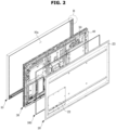
- FIG. 2 is an exploded perspective view illustrating the display apparatus according to the embodiment of the disclosure.
- the display apparatus 1 may include a housing 10 forming the external appearance thereof.
- the housing 10 may have an opening 10a.
- the opening 10a may be provided to pass therethrough from the front surface to the rear surfaces of the housing 10.
- An image displayed by a display module 30 may be viewed to the outside through the opening 10a.
- the housing 10 may have a box shape with front and rear surfaces that are open.
- the housing 10 may be provided to accommodate the display module 30 therein.
- the housing 10 may include a bezel portion 11 covering a front edge of the display module 30 and a side portion 12 bent from an edge of the bezel portion 11 rearward.
- the display apparatus 1 may include the display module 30.
- the display module 30 may include a display panel on which an image is displayed.
- the display module 30 may be disposed inside the housing 10 such that an image displayed on the display panel is exposed to the outside of the housing 10 through the opening 10a.
- the display module 30 may further include a backlight unit that supplies light to the display panel.
- the backlight unit may be arranged while being spaced apart from the rear side of the display panel.
- the backlight unit may include a plurality of light sources for generating light.
- the plurality of light sources represent an element that emits light.
- the plurality of light sources may include not only Light Emitting Diodes (LEDs), but also all elements or devices that generate and emit light.
- the display apparatus 1 may include a direct type backlight unit in which the light source is disposed directly below the display panel, or an edge type backlight unit in which the light source is disposed on a side of the display panel, as a non-emissive display panel.
- the display apparatus 1 may include an emissive type display panel in which a plurality of pixels constituting the display panel generate light by themselves to generate an image. That is, the display apparatus 1 according to the concept of the disclosure is not limited on the type of the display panel or the backlight unit.
- a rear chassis may be provided on the rear surface of the display module 30.
- the rear chassis may be provided to cover the rear surface of the display module 30.
- a printed circuit board may be mounted on the rear chassis.
- a fan 50 may be mounted on the rear chassis.
- a support bracket 40 may be mounted on the rear chassis.
- the fan 50 may be installed on the rear chassis that forms the rear of the display module 30.
- the fan 50 may be disposed in a closed space formed by the housing 10, a housing cover 20, the rear chassis, and a sealing member 100.
- the fan 50 may form an airflow in the closed space to discharge heat generated from the display module 30 to the outside of the display apparatus 1.
- the fan 50 may allow air existing between the display module 30 and the housing cover 20 to smoothly flow, to discharge heat from the display module 30 to the housing cover 20.
- the support bracket 40 may be mounted on the rear chassis.
- the housing cover 20 may be coupled to the support bracket 40. Details thereof will be described below.
- the display apparatus 1 may include the housing cover 20 coupled to the rear surface of the housing 10 to cover the opening 10a.
- the housing cover 20 may be coupled to the rear surface of the housing 10 to cover the rear surface of the display module 30.
- the display apparatus 1 may include a sealing member 100 disposed between the housing 10 and the housing cover 20 to seal a gap between the housing 10 and the housing cover 20.
- the sealing member 100 may seal the gap between the housing 10 and the housing cover 20 to prevent moisture or dust from infiltrating into the display apparatus 1.
- the sealing member 100 may be provided to have a predetermined cross-sectional shape, and the cross-sectional shape will be described below.
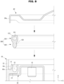
- the sealing member 100 may be disposed along edges of the housing 10. To this end, the sealing member 100 may have a length substantially corresponding to the lengths of the four sides of the housing 10.
- the sealing member 100 may be provided in a closed loop shape without having a broken part.
- the sealing member 100 is illustrated in a rectangular shape for the sake of convenience of illustration, but since the sealing member 100 is formed of a flexible material, the shape may not be fixed.
- the sealing member 100 may have an approximately elliptical shape before being coupled to the housing 10.
- FIG. 3 is an enlarged view illustrating portion B of FIG. 2 .
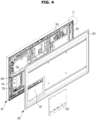
- FIG. 4 is a rear perspective view illustrating the display apparatus according to the embodiment of the disclosure, showing a state in which a housing cover is separated from the display apparatus.
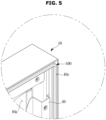
- FIG. 5 is an enlarged view illustrating portion C of FIG. 4 .
- FIG. 6 is a view illustrating a sealing member included in the display apparatus according to the embodiment of the disclosure.
- the housing 10 includes a sealing member groove 10b provided to allow the sealing member 100 to be inserted thereinto and a cover groove 10c provided to allow a bent portion 20a of the housing cover 20 to be inserted thereinto.
- Each of the sealing member groove 10b and the cover groove 10c may be formed on the rear surface of the housing 10.
- the sealing member groove 10b and the cover groove 10c may be arranged to be laterally spaced from each other.
- Each of the sealing member groove 10b and the cover groove 10c may be provided along the edge of the housing 10.
- each of the sealing member groove 10b and the cover groove 10c may be formed by a portion of the rear surface of the housing 10 being recessed forward.
- the display apparatus 1 may further include a connector case 60.
- the connector case 60 may be coupled to the rear surface of the display module 30.
- the connector case 60 may be mounted on the rear chassis of the display module 30.
- the connector case 60 may have an inner space 61 formed by being recessed toward the front of the display apparatus 1.
- a plurality of connectors 62 may be provided in the inner space 61 of the connector case 60.
- the display apparatus 1 may further include a connector sealing member 70 provided along an edge of the connector case 60.
- the connector sealing member 70 may be disposed between the connector case 60 and the housing cover 20 to seal a gap between the connector case 60 and the housing cover 20.
- the housing cover 20 may include a cover hole 21 formed at a position corresponding to the connector case 60.
- the display apparatus 1 may further include a connector cover 22 coupled to the housing cover 20 to cover the cover hole 21.
- the housing cover 20 may include a plurality of fastening holes 23 as shown in FIG. 4 .
- the housing 10 or the support bracket 40 may include a plurality of fastening holes (not shown) corresponding to the fastening holes 23 of the housing cover 20.
- a fastening member (not shown) to the fastening hole 23
- the housing cover 20 may be coupled to the housing 10 or the support bracket 40.
- the fastening member may be a screw.
- the sealing member 100 may be provided to be bendable at the corners of the housing 10 without a separate member.
- the housing 10 may be provided in a box shape having a rectangular opening.
- the housing 10 may have a square opening.
- the housing has four corners.
- the sealing member 100 needs to uniformly seal the entire circumference of the housing 10.
- the sealing member 100 needs to be bent at 90 degrees at the corner of the housing 10.
- the thickness of the sealing member may become non-uniform to cause a gap to be formed between the sealing member and the housing cover.
- the sealing member When the conventional sealing member is bent at 90 degrees, the sealing member is compressed and becomes thicker to thereby generate a gap between the housing cover and the sealing member. Moisture and dust may infiltrate through the gap, and the sealing member may not function properly.
- a separate corner sealing member for sealing the corner of the display apparatus has been provided.
- the corner sealing member bent at 90 degrees is disposed at each corner, and thus, the display apparatus is provided with four corner sealing members.
- the corner sealing member has one end and the other end respectively coupled to a long side sealing member and a short side sealing member each provided in a straight line shape.
- an adhesive needs to be applied such that the one end of the corner sealing member is bonded to the long side sealing member and an adhesive needs to be applied such that the other end of the corner sealing member is bonded to the short side sealing member.
- the sealing member includes four corner sealing members, two long-side sealing members, and two short-side sealing members, and in order for the sealing members to form a closed loop, an adhesive needs to be applied twice for each corner sealing member. Therefore, a total of eight adhesive application processes are required.
- the sealing member 100 may form a closed loop with only one adhesive application process.
- the sealing member 100 may be provided to be bendable at 90 degrees without a separate corner member at the corner of the housing 10.
- the sealing member 100 may form a closed loop with only one application of an adhesive.
- the sealing member 100 may be provided to be bendable at 90 degrees without a separate corner member even at the corner of the housing 100. Even when the sealing member 100 is bent at 90 degrees, the sealing member 100 may be not subject to a great change in thickness thereof. Accordingly, the sealing member 100 may prevent a lifting from occurring in the housing cover 20 due to a change in thickness thereof even at the corner of the housing 10. That is, even at the corner of the housing 10, a gap may not be formed between the sealing member 100 and the housing cover 20.
- the sealing member 100 may be provided to have a predetermined cross-sectional shape, and may be provided to extend in one direction.
- the sealing member 100 may be provided as a straight line shaped member having a uniform cross-sectional shape. Since the sealing member 100 is formed of a flexible material, the sealing member may be bent as described above, and a closed loop may be formed by bonding one end 101 of the sealing member to the other end 102 of the sealing member with an adhesive. That is, the closed loop may be formed with only one application of the adhesive.
- the production process of the sealing member may be simplified, and thus, productivity of the sealing member may be improved.
- FIG. 7 is a cross-sectional view illustrating the sealing member shown in FIG. 6 .
- the sealing member 100 may include a head portion 110 and a protrusion portion 120 extending from the head portion 110.
- the sealing member 100 may be disposed between the housing 10 and the housing cover 20 to seal a gap between the housing 10 and the housing cover 20.
- the sealing member 100 may be disposed such that the head portion 110 comes in contact with the housing cover 20 and the protrusion portion 120 is inserted into the sealing member groove 10b of the housing 10.
- the head portion 110 may include a hollow 111.
- the hollow 111 may be provided in an approximately semicircular or arc shape.
- the hollow 111 may have an upper portion in an approximately semicircular shape and a lower portion in an approximately rectangular shape.
- the hollow 111 may have an upper portion in a semi-circular shape, and the head portion 110 has an upper surface in a semi-circular shape to correspond in shape to the upper portion of the hollow 111.
- the hollow 111 may have a cross section including an arc portion in an arc shape and a straight portion provided in a straight line.
- the arc portion may be arranged in the upper side of the hollow 111, and the straight portion may be arranged in the lower side of the hollow 111.
- the upper surface of the head portion 110 may be provided in a curved surface.
- the upper surface of the head portion 110 may be provided in an arc shape, as described above.
- the head portion 110 may include a contact point 112 positioned at the center of the upper surface thereof.
- the contact point 112 may indicate the highest point of the head portion 110.
- the contact point 112 may indicate a point at the highest position on the sealing member 100.
- the upper surface of the head portion 110 may be provided to come in contact with the housing cover 20. Accordingly, the upper surface of the head portion 110 may be referred to as a contact surface.
- the contact point 112 may indicate the center of the contact surface.
- the center of the contact surface may indicate the center of symmetry of the contact surface or the center point of the contact surface.
- the head portion 110 may further include a pair of protrusions 113 disposed on both sides of the contact point 112.
- the protrusion 113 disposed on one side of the contact point 112 and the protrusion 113 disposed on the other side of the contact point 112 may be symmetrically disposed with respect to the contact point 112.
- the protrusion 113 may be provided to have an approximately semicircular cross section. Since the contact point 112 is the highest point on the head portion 110, the contact point 112 may be located higher than the highest point on the protrusion 113. Although not shown in the drawing, the contact point 112 may be located on the same level as the highest point on the protrusion 113. That is, the contact point 112 may be located at the same height as the highest point on the protrusion 113.
- the head portion 110 may further include a support portion 114 that forms a lower surface of the head portion 110 and protrudes to lateral sides of the protrusion portion 120.
- the support portion 114 may be provided to come in contact with a support wall 14 of the housing 10 to be described below.
- the support portion 114 may be supported by the support wall 14.
- the protrusion portion 120 may be formed to extend downward from the head portion 110.
- the protrusion portion 120 may be connected to the support portion 114.
- the protrusion portion 120 and the head 110 may be integrally formed with each other.
- the sealing member 100 may be formed by extruding a base material formed of a flexible material, such as rubber.
- the protrusion portion 120 may further include a fixing groove 121 provided to allow a fixing protrusion 15, which will be described below, to be inserted thereinto.
- the fixing grooves 121 may be provided on both sides of the protrusion portion 120.
- the fixing grooves 121 may be provided in a pair. As the fixing protrusion 15 to be described below is inserted into the fixing groove 121, the sealing member 100 inserted into the sealing member groove 10b may be prevented from being withdrawn from the sealing member groove 10b. The coupling force between the sealing member 100 and the sealing member groove 10b may be increased.
- the protrusion portion 120 may further include a guide portion 122 provided to guide the protrusion portion 120 when the sealing member 100 is inserted into the sealing member groove 10b.
- the guide portion 122 may be provided at a lower end of the protrusion portion 120, and may be provided to have a width that decreases as being extended downward. With the guide portion 122, the protrusion portion 120 may be smoothly inserted into the sealing member groove 10b. Accordingly, the sealing member 100 may be easily inserted into the sealing member groove 10b, and assembly and productivity may be improved.
- the height h1 of the head portion 110 in the upper and lower side direction on the drawing is provided to be smaller than the height h2 of the protrusion portion 120 in the upper and lower side direction on the drawing. This may be expressed as an equation as follows. h1 ⁇ h2
- the coupling force of the sealing member 100 to the sealing member groove 10b may be increased.
- the sealing member 100 may be easily separated from the sealing member groove 10b by an external force.
- the sealing member 100 may be separated from the corner of the housing 10 where a strong coupling force is required.
- a gap may be formed between the housing 10 and the housing cover 20, and moisture and dust may infiltrate into the gap.
- the height h2 of the protrusion portion 120 is greater than the height h1 of the head portion 110, so that the sealing member 100 may be coupled to the sealing member groove 10b with a strong coupling force. Accordingly, even when the sealing member 100 is bent at 90 degrees at the corner of the housing 10, the sealing member 100 may be prevented from being withdrawn from the sealing member groove 10b.
- the sealing member 100 may seal a gap between the housing 10 and the housing cover 20 even at the corner of the housing 10, and prevent moisture and dust from infiltrating into the gap.
- the length of the sealing member 100 in the left and right side direction on FIG. 7 may be referred to as a width.
- the maximum width w1 of the head portion 110 may be equal to the width w1 of the support portion 114.
- the head portion 110 may have a maximum width at the support portion 114.
- the protrusion portion 120 may have a maximum width at the upper end thereof connected to the head portion 110.
- the maximum width w1 of the head portion 110 and the maximum width of the protrusion portion 120 may be set to satisfy the following relational expression. w1*2/3 ⁇ w2
- the maximum width w2 of the protrusion portion 120 may be provided larger than 2/3 of the maximum width w1 of the head portion 110.
- the width of the protrusion portion is excessively small compared to the width of the head portion, which causes a difficulty in stably seating the sealing member in the sealing member groove.
- an adhesive is applied to the sealing member groove before the sealing member is inserted into the sealing member groove.
- such a process needs to be performed several to tens of times along the edge of the housing. Accordingly, the assembling performance of the sealing member is lowered and productivity is lowered.
- the width of the protrusion portion 120 may be sufficiently large compared to the width of the head portion 110. Accordingly, the sealing member 100 may be stably seated in the sealing member groove 10b without application of a separate adhesive. An operator may easily couple the sealing member 100 to the sealing member groove 10b using a rolling jig (not shown) and the like. In this case, a process of applying an adhesive to the sealing member groove 10b or the sealing member 100 may be omitted. Accordingly, according to the concept of the disclosure, when assembling the sealing member 100 to the sealing member groove 10b, assembling performance is improved, and further, the productivity of the display apparatus 1 may be improved.
- FIG. 8 is a view illustrating cross sections of a housing, a sealing member, and a housing cover included in the display apparatus according to the embodiment of the disclosure before being coupled to each other.
- FIG. 9 is a view illustrating cross sections of a housing, a sealing member, and a housing cover included in the display apparatus according to the embodiment of the disclosure which are coupled to each other.
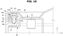
- FIG. 10 is a cross-sectional view taken along line A-A' of FIG. 1 , which shows a state in which the housing, the sealing member, and the housing cover are coupled to each other.
- the support bracket 40 may be accommodated in the housing 10.
- the support bracket 40 may be coupled to the rear chassis of the display module 30.
- the housing cover 20 may be provided to cover the rear surface of the housing 10.
- the disclosure is not limited thereto, and the housing cover 20 may be provided to be directly coupled to the housing 10 or the rear chassis of the display module 30 without using the support bracket 40.
- a term “lateral (sideways)” indicates a direction parallel to the x-axis shown in FIGS. 8 to 10 . Further, “upward” or “downward” indicates a direction parallel to the y-axis shown in FIGS. 8 to 10 .
- the housing 10 may include an extension portion 13 extending laterally from the side portion 12 toward the inside of the housing 10.
- the housing 10 may include a pair of support walls 14 extending upward from the extension portion 13.
- the sealing member groove 10b formed to allow the sealing member 100 to be inserted thereinto may be defined by the pair of support walls 14 and the extension portion 13.
- Each of the pair of support walls 14 may further include a fixing protrusion 15 protruding toward the sealing member groove 10b.
- the fixing protrusion 15 may be provided to be inserted into the fixing groove 121 of the sealing member 100. Since the fixing protrusion 15 is inserted into the fixing groove 121, the sealing member 100 may be more stably coupled to the sealing member groove 10b. As the fixing protrusion 15 is inserted into the fixing groove 121, the coupling force between the sealing member 100 and the sealing member groove 10b may be increased.
- the protrusion portion 120 of the sealing member 100 may be inserted into the sealing member groove 10b.
- the sealing member 100 when the sealing member 100 is inserted into the sealing member groove 10b, the sealing member 100 may be stably seated in the sealing member groove 10b without an adhesive being applied to the sealing member 100 or the sealing member groove 10b.
- the operator may easily seat the sealing member 100 in the sealing member groove 10b using a rolling jig (not shown) or the like. Accordingly, assembly and productivity of the display apparatus 1 may be improved.
- the housing cover 20 may be coupled to the support bracket 40.
- the housing cover 20 includes the plurality of fastening holes (23 in FIG. 11 ), and the support bracket 40 may include a fastening portion 41 corresponding to the fastening hole 23 of the housing cover 20.
- the user may couple the housing cover 20 to the support bracket 40 by passing a fastening member (not shown), such as a screw, through the fastening hole 23 and then fastening the fastening member to the fastening portion 41.
- the housing cover 20 may cover the rear surface of the housing 10.
- the housing cover 20 may cover the rear surface of the display module 30.
- the housing cover 20 may be coupled to the housing 10 rather than to the support bracket 40, and the housing cover 20 may be coupled to the rear chassis forming the rear surface of the display module 30.
- the housing cover 20 may include the bent portion 20a formed by one end of the housing cover 20 being bent downward.
- the bent portion 20a may be inserted into the cover groove 10c of the housing 10.
- the bent portion 20a may be inserted into the cover groove 10c, thereby primarily preventing moisture and dust from flowing into the gap between the housing cover 20 and the housing 10.
- waterproof and dustproof effect may not be ensured.
- the head portion 110 of the sealing member 100 may be compressed by the housing cover 20 as shown in FIG. 10 .
- the head portion 110 of the sealing member 100 when the head portion 110 of the sealing member 100 is compressed by the housing cover 20, at least three points 112, 113a, and 113b are provided to make line contact with the housing cover 20.
- the head portion 110 may come in contact with the housing cover 20 at the contact point 112 as well points 113a and 113b each of the pair of protrusions 113 in a line contact manner.
- the upper surface of the sealing member is provided as a flat surface.
- the sealing member has been often biased to one side relative to the extending direction of the sealing member in a process of the sealing member come in contact with the housing cover.
- part of the sealing member is biased to one side, and remaining part of the sealing member is biased to the other side.
- a contact area between the upper surface of the sealing member and the housing cover may be reduced, thereby reducing the sealing ability.
- the gap between the sealing member and the housing cover may increase, and the sealing performance may be significantly lowered.
- the head portion 110 of the sealing member 100 may be provided to make a line contact with the housing cover 20 on at least three points 112, 113a, and 113b. Accordingly, the contact area between the sealing member 100 and the housing cover 20 may be increased, and the sealing performance of the sealing member 100 may be improved.
- the hollow 111 of the sealing member 100 is provided in a substantially semicircular shape, and the upper shape of the head portion 110 is also provided in a semicircular shape, even when the head portion 110 is compressed by the housing cover 20, the head portion 110 may be prevented from being biased to one side or the other side of the protrusion portion 120.
- the maximum width w2 of the protrusion 120 is relatively large, the head portion 110 may be prevented from being biased to one side or the other side of the protrusion portion 110 in a state in which the protrusion portion 120 is inserted into the sealing member groove 10b.
- the sealing member 100 even when the sealing member 100 is compressed by the housing cover 20, the sealing member 100 may be prevented from being biased to one side or the other side with respect to the direction in which the sealing member 100 extends.
- the sealing member 100 may be provided to make a line contact with the housing cover 20 on at least three points 112, 113a, and 113b. Accordingly, the sealing member 100 may uniformly seal the gap between the housing 10 and the housing cover 20 over the entire area of the sealing member 100. That is, the sealing ability of the sealing member 100 may be improved.
- the waterproof and dustproof capabilities of the display device 1 may be improved.
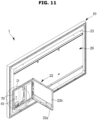
- FIG. 11 is a rear perspective view illustrating the display apparatus according to the embodiment of the disclosure, which shows a connector cover in an open state.
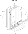
- FIG. 12 is an enlarged view illustrating portion D of FIG. 11 .
- the display apparatus 1 may include the connector case 60.
- the connector case 60 may be mounted on the rear chassis forming the rear surface of the display module 30 so as to be disposed between the rear chassis and the housing cover 20.
- the connector case 60 may have the inner space 61 formed by being recessed toward the front of the display apparatus 1.
- a plurality of connectors 62 may be provided in the inner space 61 of the connector case 60.
- the plurality of connectors 62 may include a power receiver.
- the housing cover 20 may include the connector cover 22 disposed at a position corresponding to the connector case 60. As shown in FIG. 11 , the connector cover 22 may be hinged to the housing cover 20 so as to be rotatable with respect to the housing cover 20. However, the disclosure is not limited thereto. The connector cover 22 may be detachably coupled to the housing cover 20 rather than being hinged to the housing cover 20.
- the connector cover 22 may include a plurality of fastening holes 22b.
- the plurality of fastening holes 22b may be provided to correspond to a fastening portion (not shown) provided in the connector case 60.
- the user may fix the connector cover 22 to the connector case 60 by passing a fastening member (not shown) through the fastening hole 22b and then fastening the fastening member to the fastening portion.
- the connector case 60 may further include the connector sealing member 70 provided to seal a gap between the connector case 60 and the connector cover 22 when the connector cover 22 is coupled to the connector case 60 to cover the connector case 60.
- the connector sealing member 70 may prevent moisture and/or dust from entering the inner space 61 of the connector case 60 from the outside of the display apparatus 1.
- the connector cover 22 has a plurality of first cable grooves 22a allowing to pass cables (not shown) extending from the outside of the display apparatus 1 to the inner space 61.
- the connector case 60 may include a plurality of second cable grooves 63 provided to correspond to the plurality of first cable grooves 22a, respectively.
- the first cable groove 22a and the second cable groove 63 may form one hole when the connector cover 22 is coupled to the connector case 60.
- a cable (not shown) may be withdrawn from the inner space 61 to the outside of the connector case 60 through the hole. Even when the connector cover 22 covers the connector case 60, the cable (not shown) may be withdrawn out of the connector case 60 through the cable hole (not shown) formed by the first cable groove 22a and the second cable groove 63.
- the sealing member 70 may further include a cable hole sealing portion 71 inserted into the cable hole (not shown) formed by the first cable groove 22a and the second cable groove 63 to seal the cable hole (not shown).
- a plurality of connectors 62 may be provided in the connector case 60, and a user may use only some of the plurality of connectors 62 as needed.
- a cable (not shown) connected to the connector 62 may be withdrawn from the inner space 61 to the outside of the connector case 60 through the cable hole (not shown). In this case, the cable (not shown) may block the cable hole (not shown). Accordingly, the cable hole may be sealed.
- a connector 62 not used by the user does not have a cable (not shown) and thus has the cable hole (not shown) kept open.
- the cable hole sealing portion 71 may be a configuration extending from the sealing member 70 and may be inserted into a cable hole (not shown), into which a cable is not inserted as being not used by a user, to seal the cable hole (not shown).
- the cable hole sealing portions 71 may be provided corresponding in number to the number of cable holes. Accordingly, each of the cable holes may be sealed by the cable or the cable hole sealing portion 71.
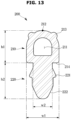
- FIG. 13 is a cross-sectional view illustrating a sealing member of a display apparatus according to another embodiment of the disclosure.
- FIG. 14 is a cross-sectional view illustrating a housing, a sealing member, and a housing cover included in the display apparatus according to the another embodiment of the disclosure which are coupled to each other.
- FIGS. 13 and 14 Details of redundant descriptions thereof will be omitted.
- a sealing member 200 may include a head portion 210 and a protrusion portion 220.
- the head portion 210 includes a hollow 211 provided in an approximately semicircular shape, a contact point 212 located at the center of an upper surface of the head portion 210, and a pair of protrusions 213 provided on both sides of the contact point 212. Further, the head portion 210 may include a support portion 214 that forms a lower surface of the head portion 210 and is supported by the support wall 14 of the housing 10.
- the protrusion portion 220 may be formed to extend downward from the head portion 210.
- the protrusion portion 220 may include a pair of fixing protrusions 221 protruding laterally from both sides of the protrusion portion 220.
- the protrusion portion 220 may include a guide portion 222 provided to guide the sealing member 200 to be inserted into the sealing member groove 10b.
- the sealing member groove 10b may be provided with a fixing groove 15a.
- each of the pair of support walls 14 may be provided with the fixing groove 15a formed in a shape corresponding to the fixing protrusion 221 of the protrusion portion 220.
- the fixing groove 15a may be formed by a portion of the support wall 14 being recessed inward. As the fixing protrusion 221 is inserted into the fixing groove 15a, the coupling force between the sealing member 200 and the sealing member groove 10b may be increased. Accordingly, the sealing member 200 may not be easily withdrawn from the sealing member groove 10b.
- the display apparatus can be provided with a sealing member having an improved structure
- the display apparatus can be provided with waterproof and dustproof functions, and improved assembly performance and productivity.
Landscapes
- Engineering & Computer Science (AREA)
- Physics & Mathematics (AREA)
- Theoretical Computer Science (AREA)
- General Physics & Mathematics (AREA)
- Microelectronics & Electronic Packaging (AREA)
- General Engineering & Computer Science (AREA)
- Nonlinear Science (AREA)
- Computer Hardware Design (AREA)
- Human Computer Interaction (AREA)
- Mathematical Physics (AREA)
- Chemical & Material Sciences (AREA)
- Crystallography & Structural Chemistry (AREA)
- Optics & Photonics (AREA)
- Signal Processing (AREA)
- Multimedia (AREA)
- Life Sciences & Earth Sciences (AREA)
- Health & Medical Sciences (AREA)
- Biodiversity & Conservation Biology (AREA)
- Ecology (AREA)
- Environmental & Geological Engineering (AREA)
- Environmental Sciences (AREA)
- Toxicology (AREA)
- Devices For Indicating Variable Information By Combining Individual Elements (AREA)
Applications Claiming Priority (2)
| Application Number | Priority Date | Filing Date | Title |
|---|---|---|---|
| KR1020200029965A KR102843530B1 (ko) | 2020-03-11 | 2020-03-11 | 디스플레이 장치 |
| EP21157983.4A EP3879380B1 (de) | 2020-03-11 | 2021-02-18 | Anzeigevorrichtung |
Related Parent Applications (2)
| Application Number | Title | Priority Date | Filing Date |
|---|---|---|---|
| EP21157983.4A Division EP3879380B1 (de) | 2020-03-11 | 2021-02-18 | Anzeigevorrichtung |
| EP21157983.4A Division-Into EP3879380B1 (de) | 2020-03-11 | 2021-02-18 | Anzeigevorrichtung |
Publications (4)
| Publication Number | Publication Date |
|---|---|
| EP4509910A2 true EP4509910A2 (de) | 2025-02-19 |
| EP4509910A3 EP4509910A3 (de) | 2025-04-23 |
| EP4509910C0 EP4509910C0 (de) | 2025-10-01 |
| EP4509910B1 EP4509910B1 (de) | 2025-10-01 |
Family
ID=74668774
Family Applications (2)
| Application Number | Title | Priority Date | Filing Date |
|---|---|---|---|
| EP24223806.1A Active EP4509910B1 (de) | 2020-03-11 | 2021-02-18 | Anzeigevorrichtung |
| EP21157983.4A Active EP3879380B1 (de) | 2020-03-11 | 2021-02-18 | Anzeigevorrichtung |
Family Applications After (1)
| Application Number | Title | Priority Date | Filing Date |
|---|---|---|---|
| EP21157983.4A Active EP3879380B1 (de) | 2020-03-11 | 2021-02-18 | Anzeigevorrichtung |
Country Status (6)
| Country | Link |
|---|---|
| US (2) | US11785733B2 (de) |
| EP (2) | EP4509910B1 (de) |
| KR (2) | KR102843530B1 (de) |
| CN (1) | CN113393759B (de) |
| ES (2) | ES3049194T3 (de) |
| WO (1) | WO2021182776A1 (de) |
Families Citing this family (6)
| Publication number | Priority date | Publication date | Assignee | Title |
|---|---|---|---|---|
| TWI810627B (zh) * | 2021-08-13 | 2023-08-01 | 和碩聯合科技股份有限公司 | 可釋放靜電之電子裝置 |
| USD1032599S1 (en) * | 2021-12-21 | 2024-06-25 | Thor Tech, Inc. | Display housing for recreational vehicle |
| JP7783077B2 (ja) * | 2022-02-15 | 2025-12-09 | フクダ電子株式会社 | 医用表示装置 |
| USD1101472S1 (en) | 2024-09-04 | 2025-11-11 | Sharkninja Operating Llc | Air fryer |
| USD1101481S1 (en) | 2024-09-04 | 2025-11-11 | Sharkninja Operating Llc | Air fryer adapter |
| USD1100567S1 (en) | 2024-09-04 | 2025-11-04 | Sharkninja Operating Llc | Air fryer |
Family Cites Families (44)
| Publication number | Priority date | Publication date | Assignee | Title |
|---|---|---|---|---|
| US2117807A (en) * | 1936-04-18 | 1938-05-17 | Pittsburgh Steel Drum Company | Gasket closure |
| US3065517A (en) * | 1959-07-10 | 1962-11-27 | Elgin Metal Casket Co Inc | Casket sealing means |
| US3360887A (en) * | 1965-02-23 | 1968-01-02 | Goodrich Co B F | Extruded sealing member |
| DE2137849B2 (de) * | 1971-07-29 | 1979-06-13 | Webasto-Werk W. Baier Gmbh & Co, 8031 Stockdorf | Dichtung für Schiebedächer |
| US4091961A (en) * | 1976-06-21 | 1978-05-30 | Greif Bros. Corporation | Chime protective gasket |
| US4555119A (en) * | 1981-07-22 | 1985-11-26 | Casket Shells, Inc. | Casket sealing gasket |
| US6141667A (en) * | 1994-07-12 | 2000-10-31 | Duff; Mark Blaise | Waterproofing and increasing portability of a portable computer |
| JP2581022B2 (ja) * | 1994-10-31 | 1997-02-12 | 日本電気株式会社 | 表示部付き電子機器の防塵構造 |
| US6702301B1 (en) * | 1999-09-23 | 2004-03-09 | Meritor Light Vehicle Systems, Inc. | Active window seal |
| JP3646867B2 (ja) * | 2000-09-29 | 2005-05-11 | 住友電装株式会社 | コネクタ |
| US6740809B2 (en) * | 2002-03-01 | 2004-05-25 | Andrew Corporation | Configuration for sealing three-dimensional enclosures |
| JP3892818B2 (ja) * | 2003-01-29 | 2007-03-14 | 西川ゴム工業株式会社 | 電磁波シールド用のパッキン |
| US8069615B2 (en) * | 2007-02-27 | 2011-12-06 | Parker-Hannifin Corporation | Supported hollow seal |
| KR20090050165A (ko) * | 2007-11-15 | 2009-05-20 | 주식회사 만앤휴멜동우 | 자동차용 에어클리너의 시일구조 |
| US20120135300A1 (en) | 2010-02-02 | 2012-05-31 | Shinji Ota | Battery storage case and battery pack having the same |
| US9457941B2 (en) * | 2010-02-03 | 2016-10-04 | Tomoya Kawakami | Multipurpose elastic loop gasket |
| JP2011179588A (ja) * | 2010-03-01 | 2011-09-15 | Denso Corp | ガスケット |
| JP5671865B2 (ja) * | 2010-08-02 | 2015-02-18 | 富士電機株式会社 | 筐体 |
| KR101022355B1 (ko) | 2010-09-02 | 2011-03-22 | 엘아이지넥스원 주식회사 | 전자기파 차폐 및 전자기기 밀봉용 복합 가스켓, 및 이를 포함하는 전자기기 |
| CN102695385A (zh) * | 2011-03-25 | 2012-09-26 | 鸿富锦精密工业(深圳)有限公司 | 电子装置 |
| JP5883296B2 (ja) * | 2012-01-20 | 2016-03-09 | 株式会社ヴァレオジャパン | スイッチ |
| JP2013211844A (ja) * | 2012-02-29 | 2013-10-10 | Trade Works Co Ltd | 防水ケース及び防水ケースの製造方法 |
| JP5342030B2 (ja) * | 2012-02-29 | 2013-11-13 | 株式会社東芝 | 電子機器 |
| US9119285B2 (en) * | 2012-06-19 | 2015-08-25 | Apple Inc. | Conductive gaskets with internal cavities |
| KR102074513B1 (ko) | 2012-07-30 | 2020-02-06 | 엘지전자 주식회사 | 방수 구조 및 그를 구비한 전자 장치 |
| JP2014081066A (ja) * | 2012-09-25 | 2014-05-08 | Toyoda Gosei Co Ltd | ガスケット |
| JP5983301B2 (ja) * | 2012-10-22 | 2016-08-31 | 富士通株式会社 | 電子機器 |
| DE102013101263B4 (de) * | 2013-02-08 | 2022-12-01 | Denso Corporation | Dichtungsanordnung zwischen zwei Gehäuseteilen |
| JP2014183102A (ja) * | 2013-03-18 | 2014-09-29 | Fujitsu Ltd | 電子機器 |
| JP6189078B2 (ja) * | 2013-04-24 | 2017-08-30 | 三菱電線工業株式会社 | シール材 |
| JP6524853B2 (ja) * | 2015-08-18 | 2019-06-05 | 富士通クライアントコンピューティング株式会社 | 折り畳み型情報処理装置 |
| CN205260819U (zh) * | 2015-11-30 | 2016-05-25 | 中冶南方(武汉)自动化有限公司 | 一种壳体密封结构 |
| DE102016105164A1 (de) * | 2016-03-21 | 2017-09-21 | Knorr-Bremse Gmbh | Extrusionsprofil und Verfahren zum Herstellen desselben sowie Tür für ein Fahrzeug |
| KR102214298B1 (ko) * | 2016-10-06 | 2021-02-09 | 삼성전자주식회사 | 디스플레이 장치 |
| JP2018096400A (ja) * | 2016-12-09 | 2018-06-21 | 株式会社マーレ フィルターシステムズ | 密封構造 |
| DE102017112133A1 (de) * | 2017-06-01 | 2018-12-06 | Gummi-Welz Gmbh U. Co. Kg Gummi-Kunststofftechnik-Schaumstoffe | Sicherheitsprofilleiste und Tür mit Sicherheitsprofilleiste |
| JP6577977B2 (ja) * | 2017-06-14 | 2019-09-18 | 矢崎総業株式会社 | パッキン |
| JP7095263B2 (ja) * | 2017-11-10 | 2022-07-05 | 株式会社アイシン | 車両ドアのウインドガラス支持構造 |
| KR20190061312A (ko) * | 2017-11-27 | 2019-06-05 | 평화오일씰공업주식회사 | 어큐뮬레이터용 피스톤 |
| JP2019138925A (ja) * | 2018-02-06 | 2019-08-22 | ソニーセミコンダクタソリューションズ株式会社 | 撮像装置及び筐体部品 |
| US11590021B2 (en) * | 2018-07-06 | 2023-02-28 | Kesha Williams | Feminine cooling apparatus and method |
| KR102555954B1 (ko) * | 2018-08-31 | 2023-07-19 | 삼성디스플레이 주식회사 | 표시 장치 |
| CN210068927U (zh) * | 2019-05-23 | 2020-02-14 | 苏州三星电子有限公司 | 密封结构及衣物处理装置 |
| CN217485607U (zh) * | 2021-03-02 | 2022-09-23 | 现代摩比斯株式会社 | 电池水密密封结构 |
-
2020
- 2020-03-11 KR KR1020200029965A patent/KR102843530B1/ko active Active
-
2021
- 2021-02-18 ES ES24223806T patent/ES3049194T3/es active Active
- 2021-02-18 EP EP24223806.1A patent/EP4509910B1/de active Active
- 2021-02-18 EP EP21157983.4A patent/EP3879380B1/de active Active
- 2021-02-18 ES ES21157983T patent/ES3023239T3/es active Active
- 2021-02-24 WO PCT/KR2021/002298 patent/WO2021182776A1/en not_active Ceased
- 2021-03-09 CN CN202110257770.4A patent/CN113393759B/zh active Active
- 2021-03-10 US US17/197,322 patent/US11785733B2/en active Active
-
2023
- 2023-07-18 US US18/223,153 patent/US20230363100A1/en active Pending
-
2025
- 2025-07-28 KR KR1020250102726A patent/KR20250117627A/ko active Pending
Also Published As
| Publication number | Publication date |
|---|---|
| US20230363100A1 (en) | 2023-11-09 |
| EP4509910C0 (de) | 2025-10-01 |
| EP4509910A3 (de) | 2025-04-23 |
| ES3049194T3 (en) | 2025-12-15 |
| KR20250117627A (ko) | 2025-08-05 |
| CN113393759B (zh) | 2024-02-13 |
| EP3879380C0 (de) | 2025-04-02 |
| KR20210114635A (ko) | 2021-09-24 |
| US20210289649A1 (en) | 2021-09-16 |
| EP4509910B1 (de) | 2025-10-01 |
| EP3879380A1 (de) | 2021-09-15 |
| CN113393759A (zh) | 2021-09-14 |
| WO2021182776A1 (en) | 2021-09-16 |
| ES3023239T3 (en) | 2025-05-30 |
| US11785733B2 (en) | 2023-10-10 |
| EP3879380B1 (de) | 2025-04-02 |
| KR102843530B1 (ko) | 2025-08-08 |
Similar Documents
| Publication | Publication Date | Title |
|---|---|---|
| EP4509910B1 (de) | Anzeigevorrichtung | |
| US11294215B2 (en) | Display device with simplified appearance structure and improved coupling arrangement | |
| US7929280B2 (en) | Display apparatus | |
| US8345415B2 (en) | Display apparatus | |
| JP5266565B2 (ja) | 液晶ディスプレイモジュールを含む画像表示システム | |
| US7623195B2 (en) | Structure for assembling lamp wires for backlight assembly into liquid crystal display module | |
| US6339418B1 (en) | Surface illuminant device and flat-panel display using the same | |
| US20080298001A1 (en) | Display apparatus | |
| EP3333623B1 (de) | Anzeigevorrichtung | |
| US20140063351A1 (en) | Television receiver and electronic device | |
| US12526939B2 (en) | Display device | |
| US12051880B2 (en) | Board case and display apparatus including the same | |
| KR102949156B1 (ko) | 표시 장치 | |
| US7443459B2 (en) | Liquid crystal display device | |
| TWI836929B (zh) | 顯示裝置 | |
| KR102678949B1 (ko) | 고정용 표시 장치 | |
| KR20200012592A (ko) | 슬림형 대화면 시현기 | |
| KR20060107985A (ko) | 액정표시장치 |
Legal Events
| Date | Code | Title | Description |
|---|---|---|---|
| PUAI | Public reference made under article 153(3) epc to a published international application that has entered the european phase |
Free format text: ORIGINAL CODE: 0009012 |
|
| STAA | Information on the status of an ep patent application or granted ep patent |
Free format text: STATUS: REQUEST FOR EXAMINATION WAS MADE |
|
| 17P | Request for examination filed |
Effective date: 20241230 |
|
| AC | Divisional application: reference to earlier application |
Ref document number: 3879380 Country of ref document: EP Kind code of ref document: P |
|
| AK | Designated contracting states |
Kind code of ref document: A2 Designated state(s): AL AT BE BG CH CY CZ DE DK EE ES FI FR GB GR HR HU IE IS IT LI LT LU LV MC MK MT NL NO PL PT RO RS SE SI SK SM TR |
|
| REG | Reference to a national code |
Ref country code: DE Ref legal event code: R079 Free format text: PREVIOUS MAIN CLASS: G02F0001133300 Ipc: G06F0001160000 Ref country code: DE Ref legal event code: R079 Ref document number: 602021039886 Country of ref document: DE Free format text: PREVIOUS MAIN CLASS: G02F0001133300 Ipc: G06F0001160000 |
|
| PUAL | Search report despatched |
Free format text: ORIGINAL CODE: 0009013 |
|
| AK | Designated contracting states |
Kind code of ref document: A3 Designated state(s): AL AT BE BG CH CY CZ DE DK EE ES FI FR GB GR HR HU IE IS IT LI LT LU LV MC MK MT NL NO PL PT RO RS SE SI SK SM TR |
|
| RIC1 | Information provided on ipc code assigned before grant |
Ipc: G02F 1/1339 20060101ALI20250317BHEP Ipc: H05K 5/06 20060101ALI20250317BHEP Ipc: H04N 5/64 20060101ALI20250317BHEP Ipc: G06F 1/16 20060101AFI20250317BHEP |
|
| GRAP | Despatch of communication of intention to grant a patent |
Free format text: ORIGINAL CODE: EPIDOSNIGR1 |
|
| STAA | Information on the status of an ep patent application or granted ep patent |
Free format text: STATUS: GRANT OF PATENT IS INTENDED |
|
| GRAS | Grant fee paid |
Free format text: ORIGINAL CODE: EPIDOSNIGR3 |
|
| RIC1 | Information provided on ipc code assigned before grant |
Ipc: G06F 1/16 20060101AFI20250717BHEP Ipc: H04N 5/64 20060101ALI20250717BHEP Ipc: H05K 5/06 20060101ALI20250717BHEP Ipc: G02F 1/1339 20060101ALI20250717BHEP |
|
| INTG | Intention to grant announced |
Effective date: 20250729 |
|
| GRAA | (expected) grant |
Free format text: ORIGINAL CODE: 0009210 |
|
| STAA | Information on the status of an ep patent application or granted ep patent |
Free format text: STATUS: THE PATENT HAS BEEN GRANTED |
|
| AC | Divisional application: reference to earlier application |
Ref document number: 3879380 Country of ref document: EP Kind code of ref document: P |
|
| AK | Designated contracting states |
Kind code of ref document: B1 Designated state(s): AL AT BE BG CH CY CZ DE DK EE ES FI FR GB GR HR HU IE IS IT LI LT LU LV MC MK MT NL NO PL PT RO RS SE SI SK SM TR |
|
| REG | Reference to a national code |
Ref country code: GB Ref legal event code: FG4D Ref country code: CH Ref legal event code: F10 Free format text: ST27 STATUS EVENT CODE: U-0-0-F10-F00 (AS PROVIDED BY THE NATIONAL OFFICE) Effective date: 20251001 |
|
| REG | Reference to a national code |
Ref country code: DE Ref legal event code: R096 Ref document number: 602021039886 Country of ref document: DE |
|
| REG | Reference to a national code |
Ref country code: IE Ref legal event code: FG4D |
|
| U01 | Request for unitary effect filed |
Effective date: 20251015 |
|
| U07 | Unitary effect registered |
Designated state(s): AT BE BG DE DK EE FI FR IT LT LU LV MT NL PT RO SE SI Effective date: 20251022 |
|
| REG | Reference to a national code |
Ref country code: ES Ref legal event code: FG2A Ref document number: 3049194 Country of ref document: ES Kind code of ref document: T3 Effective date: 20251215 |
|
| U20 | Renewal fee for the european patent with unitary effect paid |
Year of fee payment: 6 Effective date: 20260223 |
|
| PGFP | Annual fee paid to national office [announced via postgrant information from national office to epo] |
Ref country code: GB Payment date: 20260122 Year of fee payment: 6 |
|
| PGFP | Annual fee paid to national office [announced via postgrant information from national office to epo] |
Ref country code: ES Payment date: 20260324 Year of fee payment: 6 |
|
| PG25 | Lapsed in a contracting state [announced via postgrant information from national office to epo] |
Ref country code: NO Free format text: LAPSE BECAUSE OF FAILURE TO SUBMIT A TRANSLATION OF THE DESCRIPTION OR TO PAY THE FEE WITHIN THE PRESCRIBED TIME-LIMIT Effective date: 20260101 |
|
| PG25 | Lapsed in a contracting state [announced via postgrant information from national office to epo] |
Ref country code: HR Free format text: LAPSE BECAUSE OF FAILURE TO SUBMIT A TRANSLATION OF THE DESCRIPTION OR TO PAY THE FEE WITHIN THE PRESCRIBED TIME-LIMIT Effective date: 20251001 |
|
| PG25 | Lapsed in a contracting state [announced via postgrant information from national office to epo] |
Ref country code: RS Free format text: LAPSE BECAUSE OF FAILURE TO SUBMIT A TRANSLATION OF THE DESCRIPTION OR TO PAY THE FEE WITHIN THE PRESCRIBED TIME-LIMIT Effective date: 20260101 |
|
| PG25 | Lapsed in a contracting state [announced via postgrant information from national office to epo] |
Ref country code: IS Free format text: LAPSE BECAUSE OF FAILURE TO SUBMIT A TRANSLATION OF THE DESCRIPTION OR TO PAY THE FEE WITHIN THE PRESCRIBED TIME-LIMIT Effective date: 20260201 |