EP4502377A1 - Hochdruckreinigungsgerät - Google Patents
Hochdruckreinigungsgerät Download PDFInfo
- Publication number
- EP4502377A1 EP4502377A1 EP23189259.7A EP23189259A EP4502377A1 EP 4502377 A1 EP4502377 A1 EP 4502377A1 EP 23189259 A EP23189259 A EP 23189259A EP 4502377 A1 EP4502377 A1 EP 4502377A1
- Authority
- EP
- European Patent Office
- Prior art keywords
- cleaning device
- pressure
- pressure pump
- axis
- rotation
- Prior art date
- Legal status (The legal status is an assumption and is not a legal conclusion. Google has not performed a legal analysis and makes no representation as to the accuracy of the status listed.)
- Pending
Links
Images



Classifications
-
- F—MECHANICAL ENGINEERING; LIGHTING; HEATING; WEAPONS; BLASTING
- F04—POSITIVE - DISPLACEMENT MACHINES FOR LIQUIDS; PUMPS FOR LIQUIDS OR ELASTIC FLUIDS
- F04B—POSITIVE-DISPLACEMENT MACHINES FOR LIQUIDS; PUMPS
- F04B17/00—Pumps characterised by combination with, or adaptation to, specific driving engines or motors
- F04B17/06—Mobile combinations
-
- B—PERFORMING OPERATIONS; TRANSPORTING
- B08—CLEANING
- B08B—CLEANING IN GENERAL; PREVENTION OF FOULING IN GENERAL
- B08B3/00—Cleaning by methods involving the use or presence of liquid or steam
- B08B3/02—Cleaning by the force of jets or sprays
- B08B3/026—Cleaning by making use of hand-held spray guns; Fluid preparations therefor
-
- B—PERFORMING OPERATIONS; TRANSPORTING
- B08—CLEANING
- B08B—CLEANING IN GENERAL; PREVENTION OF FOULING IN GENERAL
- B08B13/00—Accessories or details of general applicability for machines or apparatus for cleaning
-
- F—MECHANICAL ENGINEERING; LIGHTING; HEATING; WEAPONS; BLASTING
- F04—POSITIVE - DISPLACEMENT MACHINES FOR LIQUIDS; PUMPS FOR LIQUIDS OR ELASTIC FLUIDS
- F04B—POSITIVE-DISPLACEMENT MACHINES FOR LIQUIDS; PUMPS
- F04B37/00—Pumps having pertinent characteristics not provided for in, or of interest apart from, groups F04B25/00 - F04B35/00
- F04B37/10—Pumps having pertinent characteristics not provided for in, or of interest apart from, groups F04B25/00 - F04B35/00 for special use
- F04B37/12—Pumps having pertinent characteristics not provided for in, or of interest apart from, groups F04B25/00 - F04B35/00 for special use to obtain high pressure
-
- B—PERFORMING OPERATIONS; TRANSPORTING
- B08—CLEANING
- B08B—CLEANING IN GENERAL; PREVENTION OF FOULING IN GENERAL
- B08B2203/00—Details of cleaning machines or methods involving the use or presence of liquid or steam
- B08B2203/02—Details of machines or methods for cleaning by the force of jets or sprays
- B08B2203/0223—Electric motor pumps
Definitions
- the invention relates to a high-pressure cleaning device according to the preamble of claim 1.
- the invention is based on the object of developing a generic high-pressure cleaning device in such a way that it can be designed compactly.
- the invention is based on the finding that in conventional high-pressure cleaning devices the arrangement of the high-pressure pump and the hose reel is unfavourable. They are often arranged far apart from each other, so that a supply line from the high-pressure pump to the hose reel is required. This wastes installation space and material.
- the high-pressure pump and a drive of the high-pressure pump are arranged one behind the other in the direction of movement of the at least one piston of the high-pressure pump.
- the hose reel is often arranged behind them in the same direction, namely in the direction of movement of the at least one piston. arranged horizontally. This requires a lot of installation space, particularly in the direction of movement of at least one piston of the high-pressure pump.
- the rotation axis of the hose reel runs transversely, in particular perpendicularly to the direction of movement of the at least one piston.
- the hose reel and the high-pressure pump are arranged in such a way that the rotation axis of the hose reel intersects the high-pressure pump. This makes it possible to arrange the high-pressure pump and the hose reel very close to one another. A long connecting line between the high-pressure pump and the hose reel is therefore not necessary. In addition, little installation space is required in the direction of movement of the at least one piston of the high-pressure pump. This enables a compact design of the high-pressure cleaning device.
- the center axis of the high-pressure pump is a central axis of the at least one piston.
- the center axis is the longitudinal center axis of the piston.
- the center axis is an axis of symmetry with respect to the set of all pistons.
- the pistons can be arranged on an imaginary circular line.
- the center axis then runs through the center of the circular line.
- the center axis is expediently at the same distance from all pistons. This distance is measured perpendicular to the direction of movement of the at least one piston.
- the pistons are arranged in a row, in particular on an imaginary straight line. The center axis then runs through the straight line and divides the set of all pistons along the straight line into two equal halves.
- the high-pressure pump comprises a swash plate.
- the swash plate is mounted so as to be rotatable about a disk rotation axis.
- the swash plate expediently drives at least one piston of the high-pressure pump.
- the center axis of the high-pressure pump runs coaxially to the disk rotation axis of the swash plate.
- the high-pressure pump comprises in particular a pump inlet.
- the pump inlet is also referred to as a liquid inlet.
- the pump inlet is designed such that liquid can enter the high-pressure pump through the pump inlet in the direction of movement of the at least one piston.
- the rotation axis of the hose reel intersects the center axis of the high-pressure pump.
- the rotation axis of the hose reel and the center axis of the high-pressure pump are oriented perpendicular to each other.
- the hose reel has a drum distance from the central axis measured in the direction of the rotation axis of the hose reel.
- the high-pressure cleaning device has a maximum width measured in the direction of the rotation axis.
- the drum distance is advantageously at most 55%, in particular at most 40%, in particular at most 30% of the maximum width.
- the hose reel is arranged at a small drum distance from the central axis.
- the high-pressure cleaning device is designed to be compact.
- the hose reel has a reel width measured in the direction of the rotation axis of the hose reel.
- the reel spacing is advantageously at most 70%, in particular at most 55%. This also enables a compact design of the high-pressure cleaning device, in particular in the transverse direction, in particular the direction perpendicular to the central axis of the high-pressure pump.
- the drum width is expediently at most 60%, in particular at most 50% of the maximum width of the high-pressure cleaning device. This allows the high-pressure cleaning device to be designed to be compact, in particular in the transverse direction, in particular in the direction perpendicular to the central axis.
- the hose reel is arranged in the area of an outer wall of the housing.
- the hose reel is expediently arranged outside the housing.
- the hose reel is only partially covered by an outer wall of the housing. It can also be provided that the hose reel is arranged inside the housing.
- the housing at least partially limits the high-pressure cleaning device to the outside.
- the high-pressure pump has a rigid base body.
- the high-pressure cleaning device in particular has a rigid connecting element.
- the connecting element is part of the high-pressure pump.
- the connecting element is rigid.
- the connecting element is a die-cast part.
- the connecting element is advantageously arranged between the hose reel and the rigid base body of the high-pressure pump, in particular with respect to the transverse direction, in particular the direction perpendicular to the central axis.
- the rigid connecting element is directly connected to the rigid base body of the high-pressure pump.
- the rigid base body and the rigid connecting element form a rigid structural unit of the high-pressure cleaning device.
- the high-pressure cleaning device has a liquid distributor piece.
- the liquid distributor piece is expediently held in the rigid connecting element.
- the rigid connecting element is arranged between, in particular with respect to the transverse direction, in particular with respect to the direction perpendicular to the central axis between, the liquid distributor piece and the rigid base body of the high-pressure pump.
- the liquid distributor is designed to convey the cleaning liquid into the hose reel, in particular into the reel hose.
- the hose reel is rotatably mounted on the liquid distributor.
- the high-pressure cleaning device is designed so that when the high-pressure cleaning device is in operation, cleaning liquid flows from the rigid base body of the high-pressure pump through the connecting element to the liquid distributor piece.
- no flexible line piece in particular no flexible hose, is arranged between the liquid distributor piece and the high-pressure pump.
- no flexible line piece, in particular no flexible hose is arranged between the liquid distributor piece and the base body of the high-pressure pump.
- the high-pressure pump protrudes into the hose reel in a direction transverse to the central axis, in particular in a direction perpendicular to the central axis, in particular in the direction of the rotation axis of the hose reel.
- the connecting element of the high-pressure pump protrudes into the hose reel in a direction transverse to the central axis, in particular in a direction perpendicular to the central axis, in particular in the direction of the rotation axis of the hose reel.
- the high-pressure pump overlaps the hose reel with respect to the transverse direction, in particular perpendicular to the central axis, in particular with respect to the direction of the axis of rotation over at least 30% of the reel width.
- the connecting element overlaps the hose reel with respect to the transverse direction, in particular perpendicular to the central axis, in particular with respect to the direction of the axis of rotation over at least 30% of the reel width.
- the hose reel advantageously has a receiving space on its inner outside facing the high-pressure pump that is located radially inward with respect to the axis of rotation.
- the receiving space extends in the direction radially to the axis of rotation, starting from the axis of rotation.
- the receiving space is designed to accommodate a cleaning supply line for adding cleaning agent to the cleaning liquid. This also enables a compact design of the high-pressure cleaning device.
- the receiving space has a maximum diameter measured perpendicularly, in particular radially, to the axis of rotation.
- the maximum diameter is larger than a diameter of the liquid distributor piece measured in the direction perpendicularly, in particular radially, to the axis of rotation.
- the connecting element comprises a cleaning feed opening for adding cleaning agent to the cleaning liquid.
- the cleaning feed opening is expediently arranged in the connecting element.
- the cleaning feed opening is arranged in the area of the hose reel with respect to the direction of the axis of rotation. This means that cleaning agent can be added to the cleaning liquid in a simple manner even when the high-pressure cleaning device has a compact design.
- the high-pressure cleaning device conveniently includes a battery pack.
- the battery pack is the only energy source for the high-pressure cleaning device.
- the high-pressure cleaning device is a battery-operated high-pressure cleaner.
- the high-pressure cleaning device is portable.
- the high-pressure cleaning device does not have wheels.
- the battery pack is used to supply energy to a drive of the high-pressure pump.
- the high-pressure cleaning device expediently has a battery compartment for accommodating the battery pack.
- the battery compartment and the hose reel overlap at least partially with respect to the direction of the axis of rotation.
- the battery compartment and the high-pressure pump overlap at least partially with respect to the direction of the axis of rotation.
- the high-pressure pump, the drive for the high-pressure pump and the battery compartment are overlapped with respect to the Direction of the central axis, particularly with regard to the direction of movement, one behind the other.
- This type of arrangement allows the high-pressure cleaning device to be designed very compactly.
- the high-pressure cleaning device has a handle.
- the high-pressure cleaning device can be carried using the handle.
- the arrangement of the components high-pressure pump, hose reel and battery pack is designed so that the center of gravity of the high-pressure cleaning device is below the handle. This makes it possible to carry the high-pressure cleaning device comfortably.
- the hose reel forms part of the outer contour of the high-pressure cleaning device.
- the hose reel protrudes in the direction transverse to the central axis, in particular in the direction perpendicular to the central axis, in particular in the direction of the axis of rotation with less than 35% of its reel width beyond an outer contour of the housing.
- Fig. 1 shows a high-pressure cleaning device 1.
- the high-pressure cleaning device 1 is designed for cleaning objects with pressurized cleaning fluid.
- the high-pressure cleaning device 1 is portable.
- the high-pressure cleaning device 1 has a handle 7.
- the high-pressure cleaning device 1 can be carried using the handle 7. During normal operation, the high-pressure cleaning device 1 is switched off.
- the high-pressure cleaning device 1 is a battery-operated high-pressure cleaner.
- the high-pressure cleaning device 1 has a housing 2.
- the housing 2 at least partially delimits the high-pressure cleaning device 1 towards the outside.
- the high-pressure cleaning device 1 has a hose reel 20.
- the hose reel 20 is, as shown in the Fig. 1 to 4 shown, mounted so as to be rotatable about a rotation axis 50.
- the high-pressure cleaning device 1 comprises a drum hose 21.
- the drum hose 21 can be wound up and unwound onto the hose drum 20.
- the drum hose can be wound up and unwound onto the hose drum 20.
- a high-pressure pump 10 is arranged in the housing 2, which can be used, for example, in Fig. 4 is shown. By means of the high-pressure pump 10, cleaning fluid in the high-pressure cleaning device 1 can be pressurized.
- the cleaning fluid can be placed under a pressure of at least 10 bar, in particular of at least 15 bar, in particular of at least 30 bar, in particular of at least 100 bar.
- the cleaning fluid can be placed under a pressure of at most 600 bar, in particular of at most 500 bar, using the high-pressure pump 10.
- the high-pressure pump 10 comprises at least one piston 11.
- the at least one piston 11 is in Fig. 4 shown schematically.
- the at least one piston 11 can be moved back and forth in a direction of movement 49 to generate pressure on the cleaning fluid.
- the high-pressure pump 10 comprises three pistons 11.
- the high-pressure pump has a central axis 48 running in the direction of movement 49 of the at least one piston 11.
- the central axis 48 is a central axis of the high-pressure pump 10.
- the central axis 48 of the high-pressure pump 10 is a central axis of the at least one piston 11. If the high-pressure pump 10 comprises only a single piston 11, the central axis 48 is the longitudinal central axis of the piston.
- the high-pressure pump 10 comprises several pistons 11. In this case, the central axis 48 runs in the middle of the several pistons 11.
- the central axis 48 is an axis of symmetry with respect to the set of all pistons 11. As in Fig. 8 As shown, the pistons 11 can be arranged on an imaginary circular line 17.
- the imaginary circular line is in Fig. 8 marked with a dashed line.
- the Pistons 11 are also shown schematically with a dashed line.
- the central axis 48 runs through the center of the circular line 17.
- the central axis 48 is the same distance from all pistons 11. This distance is perpendicular, in particular measured radially to the direction of movement 49 of at least one piston 11.
- the pistons 11 are arranged in a row, in particular on an imaginary straight line.
- the central axis 48 then runs through the straight line and divides the set of all pistons 11 along the straight line into two equal halves.
- the central axis 48 is then in the middle of the total set of all pistons 11.
- the central axis 48 can also run through one of the pistons 11.
- the high-pressure pump 10 comprises a swash plate 12, as in Fig. 4 shown.
- the swash plate 12 is mounted so as to be rotatable about a disk rotation axis 47.
- the swash plate 12 drives the at least one piston 11 of the high-pressure pump 10.
- the swash plate 12 rotates about the disk rotation axis 47.
- the swash plate 12 presses the at least one piston 11 in the direction of the cleaning fluid.
- the cleaning fluid is pressurized in particular in a piston chamber (not shown). The movement of the piston 11 in the direction of movement 49 towards the cleaning fluid reduces the volume of the piston chamber.
- a return element (not shown), such as a spring, is tensioned. Due to the return force of the spring, the at least one piston 11 is then pushed back away from the cleaning fluid.
- the swash plate 12 then causes the at least one piston 11 to move in the opposite direction.
- the swash plate 12 has an inclined surface for contact with the piston 11. The inclined surface runs obliquely to the disk rotation axis 47.
- the central axis 48 of the high-pressure pump 10 runs coaxial to the disk rotation axis 47 of the swash plate 12.
- the high-pressure pump 10 has an inlet valve (not shown).
- the cleaning fluid can enter the piston chamber through the inlet valve.
- an inlet valve is provided for each piston 11.
- the inlet valve is a check valve. When the cleaning fluid in the piston chamber is pressurized, the inlet valve closes.
- the high-pressure pump 10 has an outlet valve (not shown).
- the cleaning fluid can exit the piston chamber through the outlet valve and flow further in particular in the direction of the drum hose 21.
- an outlet valve is provided for each piston 11.
- the outlet valve is a check valve. It prevents flow back from the drum hose 21 into the piston chamber.
- the rotation axis 50 of the hose reel 20 runs transversely to the direction of movement 40 of the at least one piston 11.
- the rotation axis 50 runs perpendicular to the direction of movement 49 of the at least one piston 11.
- the rotation axis 50 of the hose reel 20 intersects the high-pressure pump 10.
- the high-pressure pump 10 comprises a base body 13.
- the at least one piston 11 is arranged in the base body 13.
- the high-pressure pump 10 comprises the at least one piston 11.
- Each piston 11 is assigned a piston chamber in which the cleaning fluid can be pressurized.
- Each piston chamber is assigned an inlet valve (not shown).
- Each piston chamber is assigned an outlet valve (not shown).
- the inlet valve is part of the high-pressure pump 10.
- the outlet valve is part of the high-pressure pump 10.
- the piston chamber is part of the high-pressure pump 10.
- the inlet valve is held in the base body 13.
- the Exhaust valve is held in the base body 13.
- the component which causes the back and forth movement of the at least one piston 11 in the direction of movement 49 is a component of the high-pressure pump 10.
- the swash plate 12 is a component of the high-pressure pump 10. It can also be provided that the back and forth movement of the at least one piston 11 is caused by a crankshaft.
- the crankshaft is a component of the high-pressure pump 10.
- the swash plate 12 includes a shaft 14.
- the high-pressure pump 10 comprises a shaft housing 15. The shaft 15 is rotatably mounted in the same housing 15. If the at least one piston 11 is driven by a crankshaft to move back and forth in the direction of movement 49, the crankshaft is rotatably mounted in the shaft housing 15.
- the high-pressure cleaning device 1 comprises a drive 5.
- the drive 5 is used to drive the high-pressure pump 10.
- the drive 5 is not part of the high-pressure pump 10.
- the drive 5 is an electric motor.
- the drive 5 is a direct current motor.
- the drive 5 is a brushless direct current motor.
- the brushless direct current motor is also referred to as an EC motor.
- the high pressure pump 10 comprises an inlet nozzle 16. Cleaning fluid can enter the base body 13 of the high pressure pump 10 through the inlet nozzle 16.
- the inlet nozzle 16 is fixed to the base body 13.
- the inlet nozzle 16 is fixed in particular directly to the base body 13.
- the inlet nozzle 16 is rigid.
- the inlet nozzle 16 does not comprise a flexible element such as a flexible hose.
- the inlet nozzle 16 is in particular a die-cast part.
- a flexible hose for supplying cleaning fluid can be connected to the inlet nozzle 16.
- a coupling 8 is provided for this purpose.
- the coupling 8 is not part of the high pressure pump 10.
- the hose for supplying the cleaning fluid can be attached to the coupling 8 by means of a suitable counter-coupling.
- the hose for supplying the cleaning fluid is attached to the inlet nozzle 16 by means of a clamp or similar.
- the Cleaning fluid is supplied to the at least one inlet valve of the piston chamber of the at least one piston 11.
- the cleaning fluid is supplied from the inlet connection 16 to several inlet valves of the several pistons 11.
- the inlet connection 16 represents a common inlet of cleaning fluid for all pistons 11 of the high-pressure pump 10.
- the inlet connection 16 extends along the direction of movement 49.
- the inlet connection 16 protrudes in the direction of movement 49, in the direction away from the shaft housing 15, over the base body 13 of the high-pressure pump 10.
- the high-pressure pump 10 comprises a connecting element 30.
- the connecting element 30 is also referred to as the pump outlet of the high-pressure pump 10.
- the connecting element 30 represents a common outlet for the cleaning fluid emerging from the outlet valves of the multiple pistons 11.
- the connecting element 30 is rigid.
- the connecting element 30 is fixed to the base body 13 of the high-pressure pump 10.
- the connecting element 30 is fixed in particular directly to the base body 13 of the high-pressure pump 10.
- the connecting element 30 does not comprise a flexible hose.
- the connecting element 30 is a die-cast part.
- the connecting element 30 is formed in one piece.
- the connecting element 30 extends along a direction that runs transversely to the direction of movement 49, in particular perpendicular to the direction of movement 49, in particular radially to the central axis 48.
- the high-pressure cleaning device 1 comprises a liquid distributor piece 3.
- the liquid distributor piece 3 connects the connecting element 30 directly to the hose reel 20, in particular to the reel hose 21.
- the hose reel 20 is rotatably mounted on the liquid distributor piece 3.
- the cleaning liquid is guided into the reel hose 21 through the liquid distributor piece 3.
- the liquid distributor piece 3 is held in the rigid connecting element 30 of the high-pressure pump 10.
- the liquid distributor piece 3 is rigid.
- the liquid distributor piece 3 does not comprise a flexible hose.
- the rigid connecting element 30 is directly connected to the rigid base body 13 of the high-pressure pump 20.
- cleaning fluid can flow from the base body 13 of the high-pressure pump 10 through the connecting element 30 of the high-pressure pump 10 to the fluid distributor piece 3.
- the fluid distributor piece 3 is not a component of the high-pressure pump 10.
- the high-pressure pump 10 does not comprise any flexible supply lines or discharge lines for cleaning fluid, for example in the form of hoses.
- the hose reel 20 is arranged relative to the high-pressure pump 10 such that the axis of rotation 50 of the hose reel 20 intersects the central axis 48 of the high-pressure pump 10.
- the axis of rotation 50 of the hose reel 20 and the central axis 48 of the high-pressure pump 10 are oriented perpendicular to one another.
- the axis of rotation 50 of the hose reel 20 runs in particular radially to the central axis 48 of the high-pressure pump 10.
- the rotation axis 50 of the hose reel 20 in the embodiment runs parallel to the horizontal plane. If the high-pressure cleaning device 1 is placed on the horizontal plane using the storage area provided for it, the center axis 48 runs parallel to the horizontal plane.
- the hose reel 20 comprises a first side wall 24.
- the hose reel 20 comprises a second side wall 25.
- the first side wall 24 is spaced apart from the second side wall 25 in the direction of the axis of rotation 50 of the hose reel 20.
- a receiving space for the reel hose 21 is formed between the side walls 24 and 25.
- the reel hose 21 is wound or spooled up between the side walls 24 and 25.
- the first side wall 24 is arranged closer to the high-pressure pump 10 than the second side wall 25.
- the first side wall 24 is located on the inside.
- the first side wall 24 faces the high-pressure pump 10.
- the liquid distributor piece 3 is arranged closer to the second side wall 25 than to the first side wall 24 with respect to the direction of the axis of rotation 50.
- the liquid distributor piece 3 is arranged in particular in the region of the second side wall 24 with respect to the direction of the axis of rotation 50.
- the hose reel 20 has a drum distance a measured in the direction of the rotation axis 50 of the hose reel 20 from the central axis 48 of the high-pressure pump 10.
- the drum distance a between the hose reel 20 and the central axis 48 corresponds to the distance measured in the direction of the rotation axis 50 between the central axis 48 and the first side wall 24.
- the hose reel 20 only includes the parts that can rotate about the rotation axis 50.
- the high-pressure cleaning device 1 has a maximum width b measured in the direction of the axis of rotation 50 of the hose reel 20.
- the drum spacing a is at most 50%, in particular at most 40%, in the exemplary embodiment at most 30% of the maximum width b.
- the drum spacing a is at least 10%, in the exemplary embodiment at least 20% of the maximum width b.
- the housing 2 has a maximum internal width h measured in the direction of the rotation axis 50 of the hose reel 20.
- the reel spacing a is at most 50%, in the exemplary embodiment at most 40% of the maximum internal width h.
- the reel spacing a is at least 20%, in the exemplary embodiment at least 30% of the maximum internal width h.
- the hose reel 20 has a Fig. 4 and 8 shown, measured in the direction of the axis of rotation 50 of the hose reel 20.
- the drum width c When determining the drum width c, all components of the hose reel 20 are taken into account.
- the hose reel 20 comprises a crank pin 26.
- the crank pin 26 is a component of the hose reel 20.
- the crank pin 26 must be taken into account when determining the reel width c.
- the reel width c is measured from the side of the first side wall 24 facing the high-pressure pump 10 to the outer longitudinal end of the crank pin 26.
- the drum spacing a is at most 70%, in particular at most 60%, in the embodiment at most 55% of the drum width c.
- the drum width c is at most 60%, in the embodiment at most 50% of the maximum width b of the high-pressure cleaning device 1.
- the drum width c is at least 30%, in the embodiment at least 40% of the maximum width b of the high-pressure cleaning device 1.
- the drum width c is at most 80%, in the embodiment at most 70% of the maximum internal width h of the housing 2.
- the drum width c is at least 40%, in the embodiment at least 50% of the maximum internal width h of the housing 2.
- the high pressure pump 10 has a pump width e measured in the direction of the rotation axis 50 of the hose reel 20. This is shown in the Fig. 4 and 8
- the pump width e of the high pressure pump 10 is at least 40%, in the embodiment at least 50% of the maximum width b of the high-pressure cleaning device 1.
- the pump width e is at most 70%, in the exemplary embodiment at most 60% of the maximum width b.
- the pump width e of the high-pressure pump 10 is at least 70%, in the exemplary embodiment at least 80% of the maximum internal width h of the housing 2 of the high-pressure cleaning device 1.
- the pump width e is at most 95%, in the exemplary embodiment at most 90% of the maximum internal width h.
- the connecting element 30 has a connection width f measured in the direction of the rotation axis 50 of the hose reel 20, as shown in the Fig. 4 and 8
- the connection width f is at least 15%, in the exemplary embodiment at least 25% of the maximum width b of the high-pressure cleaning device 1.
- the connection width f is at most 45%, in the exemplary embodiment at most 35% of the maximum width b of the high-pressure cleaning device 1.
- no flexible line piece in particular no flexible hose, is arranged between the liquid distributor piece 3 and the high-pressure pump 10, in particular between the liquid distributor piece 3 and the base body 13 of the high-pressure pump 10.
- This statement refers to the components of the high-pressure cleaning device 1 that are involved in the line of the cleaning liquid from the high-pressure pump 10 to the liquid distributor piece 3. All of these components are rigid. In the exemplary embodiment, all of these components - with the exception of sealing rings and screws - are die-cast components.
- the connecting element 30 projects into the hose reel 20 in the direction of the rotation axis 50.
- the high-pressure pump 10 in particular the connecting element 30, and the Hose reel 20.
- the hose reel 20 overlaps the high-pressure pump 10, in particular the connecting element 30 of the high-pressure pump 10.
- the high-pressure pump 10, in particular the connecting element 30, overlaps the hose reel 20 with respect to the direction of the axis of rotation 50 over at least 30% of the reel width c.
- the hose reel 20 has a receiving space 23 on its inner outer side 22 facing the high-pressure pump 10. This is particularly evident in the Fig. 10 and 11
- the inner outer side 22 is formed by the first side wall 22.
- the inner outer side 22 is an outer side of the first side wall 24.
- the receiving space 23 is located radially inward with respect to the axis of rotation 50. This is also shown in the Fig. 4 and 8
- the receiving space 23 is designed in the embodiment to accommodate a cleaning supply line 32.
- the cleaning supply line 32 serves to add cleaning agent to the cleaning liquid.
- the cleaning supply line 32 is in the Fig. 8 and 10
- the cleaning supply line 32 is not a component of the connecting element 30.
- the cleaning supply line 32 is not a component of the high-pressure pump 10.
- the receiving space 23 has a maximum diameter d1 measured in the direction perpendicular to the rotation axis 50.
- the liquid distributor piece 3 has a diameter d2 measured in the direction perpendicular to the rotation axis.
- the diameter d2 is the outer diameter of the liquid distributor piece 3.
- the maximum diameter d1 of the receiving space 23 is larger than the diameter d2 of the liquid distributor piece 3.
- the high-pressure pump 10, in particular the connecting element 30, has a cleaning feed opening 31, as shown in Fig. 8
- the cleaning feed opening 31 serves to add cleaning agent to the cleaning liquid. Cleaning agent can be introduced into the high-pressure pump 10, in particular into the connecting element 30, through the cleaning feed opening 31.
- the cleaning feed opening 31 is arranged in the area of the hose reel 20 with respect to the direction of the axis of rotation 30 of the hose reel 20.
- the hose reel 20 overlaps the cleaning feed opening 31. It can be provided that the cleaning feed opening 31 is arranged in the region of a cross-sectional constriction for the cleaning liquid. This region is referred to as a Venturi nozzle.
- the hose reel 20 and the high-pressure pump 10 overlap with respect to the direction of movement 49.
- the hose reel 20 completely overlaps the high-pressure pump 10 with respect to the direction of movement 49.
- the high-pressure pump 10 is arranged completely in the area of the hose reel 20 with respect to the direction of movement 49.
- the hose reel 20 and the high-pressure pump 10 are arranged one behind the other. Viewed in the direction of movement 49, the high-pressure pump 10 and the hose reel 20 are located next to each other.
- the high-pressure cleaning device 1 comprises a battery pack 4.
- the battery pack is in the Fig. 4 to 7
- the battery pack 4 is used to supply energy to the drive 5 of the high-pressure pump 10.
- the high-pressure cleaning device 1 comprises a battery compartment 6.
- the battery compartment 6 serves to accommodate the battery pack 4.
- the battery pack 4 can be inserted into the battery compartment 6 through a compartment opening of the battery compartment 6.
- the compartment opening runs closed around the insertion direction of the battery pack 4.
- the battery compartment 6 is arranged in the housing 2.
- the battery pack 4 is arranged in the housing 2. As in Fig.
- the battery compartment 6 and the hose reel 20 at least partially overlap with respect to the direction of the rotation axis 50 of the hose reel 20.
- the battery compartment 6 and the high-pressure pump 10 at least partially overlap with respect to the direction of the rotation axis 50 of the hose reel 20.
- the battery compartment 6 overlaps both the high-pressure pump 10 and the hose reel 20.
- the battery compartment 6 and the high-pressure pump 10 are arranged one behind the other.
- the battery compartment 6 and the hose reel 20 are arranged one behind the other.
- the drive 5 is arranged between the battery compartment 6 and the high-pressure pump 10.
- the drive 5 is arranged in the housing 2.
- the high-pressure pump 10 is arranged in the housing 2.
- the high-pressure pump 10, the drive 5 for the high-pressure pump 10 and the battery compartment 6 are arranged one behind the other with respect to the direction of the central axis 48, in particular with respect to the direction of movement 49.
- the hose reel 20 forms part of the outer contour of the high-pressure cleaning device 1.
- the second side wall 25 forms part of the outer contour of the high-pressure cleaning device 1.
- the reel hose 21 forms part of the outer contour of the high-pressure cleaning device 1.
- the hose reel 20, in particular the second side wall 25, continues the outer contour of the housing 2 of the high-pressure cleaning device 1.
- the hose reel 20 is arranged outside the housing 2.
- the second side wall 25 faces away from the high-pressure pump 10.
- the hose reel 20 protrudes in the direction of the rotation axis 50 of the hose reel 20 with less than 35% of its reel width c beyond the outer contour of the housing 2.
- the hose reel 20 has a side width g.
- the side width g is in Fig. 4
- the side width g is measured in the direction of the axis of rotation 50 of the hose reel 20.
- the side width g corresponds to the greatest distance between the outer sides of the side walls 24 and 25.
- the crank pin 26 is not part of the second side wall 25.
- a crank pin 26 on the second side wall 25 The holder provided for the second side wall 25 is not included in the second side wall 25 when determining the side wall width g.
- the second side wall 25 protrudes in the direction of the axis of rotation 50 of the hose reel 20 by less than 10%, in the exemplary embodiment by less than 5% of the side wall width g, beyond the outer contour of the housing 2.
- a receptacle 9 for the hose reel 20 is formed by the housing 2.
- the receptacle 9 at least partially overlaps the hose reel 20 on its peripheral side.
- the receptacle 9 is formed by a first housing component of the housing 2.
- the first housing component is connected to a second housing component of the housing 2 to form a unit.
Landscapes
- Engineering & Computer Science (AREA)
- Mechanical Engineering (AREA)
- General Engineering & Computer Science (AREA)
- Cleaning By Liquid Or Steam (AREA)
Abstract
Description
- Die Erfindung betrifft ein Hochdruckreinigungsgerät nach dem Oberbegriff des Anspruchs 1.
- Hochdruckreinigungsgeräte aus dem Stand der Technik beanspruchen in der Regel einen großen Bauraum. In jüngerer Zeit ist eine Zielsetzung bei der Konstruktion von Hochdruckreinigungsgeräten, dass sie leicht, kompakt und möglichst tragbar gestaltet sind.
- Der Erfindung liegt die Aufgabe zugrunde, ein gattungsgemäßes Hochdruckreinigungsgerät derart weiterzubilden, dass es kompakt gestaltet werden kann.
- Diese Aufgabe wird durch ein Hochdruckreinigungsgerät mit den Merkmalen des Anspruchs 1 gelöst.
- Der Erfindung liegt die Erkenntnis zugrunde, dass bei herkömmlichen Hochdruckreinigungsgeräten die Anordnung der Hochdruckpumpe und der Schlauchtrommel ungünstig getroffen ist. Oft sind sie weit voneinander entfernt angeordnet, so dass eine Zuleitung von der Hochdruckpumpe zu der Schlauchtrommel erforderlich ist. Dies verschwendet Bauraum und Material. In der Regel sind die Hochdruckpumpe und ein Antrieb der Hochdruckpumpe in Bewegungsrichtung des mindestens einen Kolbens der Hochdruckpumpe hintereinander liegend angeordnet. Oft ist in selber Richtung, nämlich in der Bewegungsrichtung des mindestens einen Kolbens auch die Schlauchtrommel dahinter liegend angeordnet. Dadurch wird insbesondere in Bewegungsrichtung des mindestens einen Kolbens der Hochdruckpumpe sehr viel Bauraum benötigt.
- Erfindungsgemäß ist vorgesehen, dass die Drehachse der Schlauchtrommel quer, insbesondere senkrecht zur Bewegungsrichtung des mindestens einen Kolbens verläuft. Die Schlauchtrommel und die Hochdruckpumpe sind so zueinander angeordnet, dass die Drehachse der Schlauchtrommel die Hochdruckpumpe schneidet. Dadurch ist es möglich, die Hochdruckpumpe und die Schlauchtrommel sehr nah beieinander anzuordnen. Eine lange Verbindungsleitung zwischen Hochdruckpumpe und Schlauchtrommel ist dadurch nicht erforderlich. Darüber hinaus wird in Bewegungsrichtung des mindestens einen Kolbens der Hochdruckpumpe wenig Bauraum beansprucht. Dadurch ist eine kompakte Gestaltung des Hochdruckreinigungsgeräts möglich.
- Insbesondere ist die Mittelachse der Hochdruckpumpe eine Zentralachse des mindestens einen Kolbens. Wenn die Hochdruckpumpe lediglich einen einzigen Kolben umfasst, ist die Mittelachse die Längsmittelachse des Kolbens. Wenn die Hochdruckpumpe mehrere Kolben umfasst, ist die Mittelachse eine Symmetrieachse bezüglich der Menge aller Kolben. Beispielsweise können die Kolben auf einer gedachten Kreislinie angeordnet sein. Die Mittelachse verläuft dann durch den Mittelpunkt der Kreislinie. In diesem Fall hat die Mittelachse zweckmäßig zu allen Kolben denselben Abstand. Dieser Abstand ist senkrecht zur Bewegungsrichtung des mindestens einen Kolbens gemessen. Es kann aber auch vorgesehen sein, dass die Kolben in einer Reihe angeordnet sind, insbesondere auf einer gedachten Geraden. Die Mittelachse verläuft dann durch die Gerade und teilt die Menge aller Kolben entlang der Geraden in zwei gleich große Hälften.
- In besonderer Ausgestaltung der Erfindung umfasst die Hochdruckpumpe eine Taumelscheibe. Die Taumelscheibe ist um eine Scheibenrotationsachse drehbar gelagert. Zweckmäßig treibt die Taumelscheibe im Betrieb des Hochdruckreinigungsgeräts den mindestens einen Kolben der Hochdruckpumpe an. Insbesondere verläuft die Mittelachse der Hochdruckpumpe koaxial zur Scheibenrotationsachse der Taumelscheibe.
- Die Hochdruckpumpe umfasst insbesondere einen Pumpeneingang. Der Pumpeneingang wird auch als Flüssigkeitseinlass bezeichnet. Insbesondere ist der Pumpeneingang so gestaltet, dass Flüssigkeit in Bewegungsrichtung des mindestens einen Kolbens in die Hochruckpumpe durch den Pumpeneingang eintreten kann.
- Vorteilhaft schneidet die Drehachse der Schlauchtrommel die Mittelachse der Hochdruckpumpe. Insbesondere sind die Drehachse der Schlauchtrommel und die Mittelachse der Hochdruckpumpe senkrecht zueinander orientiert.
- Die Schlauchtrommel weist einen in Richtung der Drehachse der Schlauchtrommel gemessenen Trommelabstand zu der Mittelachse auf. Das Hochdruckreinigungsgerät besitzt eine in Richtung der Drehachse gemessene maximale Breite. Vorteilhaft beträgt der Trommelabstand höchstens 55%, insbesondere höchstens 40%, insbesondere höchstens 30% der maximalen Breite. Dadurch ist die Schlauchtrommel in einem kleinen Trommelabstand zu der Mittelachse angeordnet. Dadurch ist das Hochdruckreinigungsgerät kompakt gestaltet.
- Die Schlauchtrommel besitzt eine in Richtung der Drehachse der Schlauchtrommel gemessene Trommelbreite. Vorteilhaft beträgt der Trommelabstand höchstens 70%, insbesondere höchstens 55%. Auch dadurch ist eine kompakte Gestaltung des Hochdruckreinigungsgeräts, insbesondere bezüglich der Richtung quer, insbesondere der Richtung senkrecht zur Mittelachse der Hochdruckpumpe möglich.
- Zweckmäßig beträgt die Trommelbreite höchstens 60%, insbesondere höchstens 50% der maximalen Breite des Hochdruckreinigungsgeräts. Dadurch kann das Hochdruckreinigungsgerät kompakt gestaltet sein, insbesondere bezüglich der Richtung quer, insbesondere der Richtung senkrecht zur Mittelachse.
- Insbesondere ist die Schlauchtrommel im Bereich einer Außenwand des Gehäuses angeordnet. Die Schlauchtrommel ist zweckmäßig außerhalb des Gehäuses angeordnet. Es kann aber auch vorgesehen sein, dass die Schlauchtrommel lediglich von einer Außenwand des Gehäuses teilweise überdeckt wird. Es kann auch vorgesehen sein, dass die Schlauchtrommel innerhalb des Gehäuses angeordnet ist.
- Insbesondere begrenzt das Gehäuse das Hochdruckreinigungsgerät zumindest teilweise nach außen hin.
- Die Hochdruckpumpe weist einen starren Grundkörper auf. Das Hochdruckreinigungsgerät weist insbesondere ein starres Verbindungselement auf. Insbesondere ist das Verbindungselement Bestandteil der Hochdruckpumpe. Im Gegensatz zu einem flexiblen Schlauch zur Leitung von Reinigungsflüssigkeit ist das Verbindungselement starr. Insbesondere ist das Verbindungselement ein Druckgussteil. Vorteilhaft ist das Verbindungselement zwischen der Schlauchtrommel und dem starren Grundkörper der Hochdruckpumpe angeordnet, insbesondere bezüglich der Richtung quer, insbesondere der Richtung senkrecht zur Mittelachse. Insbesondere ist das starre Verbindungselement unmittelbar mit dem starren Grundkörper der Hochdruckpumpe verbunden. Insbesondere bilden der starre Grundkörper und das starre Verbindungselement eine starre Baueinheit des Hochdruckreinigungsgeräts. Insbesondere besitzt das Hochdruckreinigungsgerät ein Flüssigkeitsverteilerstück. Das Flüssigkeitsverteilerstück ist zweckmäßig in dem starren Verbindungselement gehalten. Insbesondere ist das starre Verbindungselement zwischen, insbesondere bezüglich der Richtung quer, insbesondere bezüglich der Richtung senkrecht zur Mittelachse zwischen, dem Flüssigkeitsverteilerstück und dem starren Grundkörper der Hochdruckpumpe angeordnet. Zweckmäßig ist das Flüssigkeitsverteilerstück zur Weiterleitung der Reinigungsflüssigkeit in die Schlauchtrommel, insbesondere in den Trommelschlauch vorgesehen. Insbesondere ist die Schlauchtrommel drehbar auf dem Flüssigkeitsverteilerstück gelagert. Zweckmäßig ist das Hochdruckreinigungsgerät so ausgelegt, dass im Betrieb des Hochdruckreinigungsgeräts Reinigungsflüssigkeit von dem starren Grundkörper der Hochdruckpumpe durch das Verbindungselement zu dem Flüssigkeitsverteilerstück fließen kann. Insbesondere ist zwischen dem Flüssigkeitsverteilerstück und der Hochdruckpumpe kein flexibles Leitungsstück, insbesondere kein flexibler Schlauch angeordnet. Insbesondere ist zwischen dem Flüssigkeitsverteilerstück und dem Grundkörper der Hochdruckpumpe kein flexibles Leitungsstück, insbesondere kein flexibler Schlauch angeordnet.
- In vorteilhafter Weiterbildung der Erfindung ist vorgesehen, dass die Hochdruckpumpe in Richtung quer zur Mittelachse, insbesondere in Richtung senkrecht zur Mittelachse, insbesondere in Richtung der Drehachse der Schlauchtrommel in die Schlauchtrommel einragt. Insbesondere ragt das Verbindungselement der Hochdruckpumpe in Richtung quer zur Mittelachse, insbesondere in Richtung senkrecht zur Mittelachse, insbesondere in Richtung der Drehachse der Schlauchtrommel in die Schlauchtrommel ein. Dadurch ist eine besonders kompakte Gestaltung des Hochdruckreinigungsgeräts möglich. Das Verbindungselement kann vergleichsweise kurz gestaltet sein und durch das Einragen des Verbindungselements in die Schlauchtrommel wird weiterer Bauraum eingespart.
- Vorteilhaft überlappt die Hochdruckpumpe die Schlauchtrommel bezüglich der Richtung quer, insbesondere senkrecht zur Mittelachse, insbesondere bezüglich der Richtung der Drehachse über mindestens 30% der Trommelbreite. Insbesondere überlappt das Verbindungselement die Schlauchtrommel bezüglich der Richtung quer, insbesondere senkrecht zur Mittelachse, insbesondere bezüglich der Richtung der Drehachse über mindestens 30% der Trommelbreite.
- Vorteilhaft weist die Schlauchtrommel an ihrer der Hochdruckpumpe zugewandten inneren Außenseite einen bezüglich der Drehachse radial innen liegenden Aufnahmeraum auf. Insbesondere erstreckt sich der Aufnahmeraum bezüglich der Richtung radial zur Drehachse ausgehend von der Drehachse. Insbesondere ist der Aufnahmeraum zur Aufnahme einer Reinigungszuführleitung zur Beimischung von Reinigungsmittel zu der Reinigungsflüssigkeit ausgelegt. Auch dadurch ist eine kompakte Gestaltung des Hochdruckreinigungsgeräts möglich.
- Der Aufnahmeraum besitzt einen senkrecht, insbesondere radial, zur Drehachse gemessenen maximalen Durchmesser. Insbesondere ist der maximale Durchmesser größer als ein in Richtung senkrecht, insbesondere radial, zur Drehachse gemessener Durchmesser des Flüssigkeitsverteilerstücks. Dadurch stellt der Aufnahmeraum ausreichend Platz zur Aufnahme der Reinigungszuführleitung zur Verfügung.
- Insbesondere umfasst das Verbindungselement eine Reinigungszuführöffnung zur Beimischung von Reinigungsmittel zu der Reinigungsflüssigkeit. Die Reinigungszuführöffnung ist zweckmäßig in dem Verbindungselement angeordnet. Insbesondere ist die Reinigungszuführöffnung bezüglich der Richtung der Drehachse im Bereich der Schlauchtrommel angeordnet. Dadurch kann auch bei kompakter Bauweise des Hochdruckreinigungsgeräts die Beimischung von Reinigungsmittel zu der Reinigungsflüssigkeit auf einfache Weise erfolgen.
- Zweckmäßig umfasst das Hochdruckreinigungsgerät einen Akkupack. Insbesondere ist der Akkupack die einzige Energiequelle des Hochdruckreinigungsgeräts. Insbesondere ist das Hochdruckreinigungsgerät ein Akkuhochdruckreiniger.
- Insbesondere ist das Hochdruckreinigungsgerät tragbar. Insbesondere weist das Hochdruckreinigungsgerät keine Räder auf.
- Insbesondere dient der Akkupack zur Energieversorgung eines Antriebs der Hochdruckpumpe. Zweckmäßig weist das Hochdruckreinigungsgerät einen Akkuschacht zur Aufnahme des Akkupacks auf. Vorteilhaft überlappen sich der Akkuschacht und die Schlauchtrommel einander bezüglich der Richtung der Drehachse zumindest teilweise. Insbesondere überlappen sich der Akkuschacht und die Hochdruckpumpe einander bezüglich der Richtung der Drehachse zumindest teilweise. Zweckmäßig sind die Hochdruckpumpe, der Antrieb für die Hochdruckpumpe und der Akkuschacht bezüglich der Richtung der Mittelachse, insbesondere bezüglich der Bewegungsrichtung, hintereinander angeordnet. Durch diese Art der Anordnung kann das Hochdruckreinigungsgerät sehr kompakt gestaltet sein. Insbesondere besitzt das Hochdruckreinigungsgerät einen Handgriff. Mit dem Handgriff kann das Hochdruckreinigungsgerät getragen werden. Die Anordnung der Komponenten Hochdruckpumpe, Schlauchtrommel und Akkupack ist zweckmäßig so getroffen, dass der Schwerpunkt des Hochdruckreinigungsgeräts unterhalb des Handgriffs liegt. Dadurch ist ein komfortables Tragen des Hochdruckreinigungsgeräts möglich.
- In vorteilhafter Weiterbildung der Erfindung bildet die Schlauchtrommel einen Teil der Außenkontur des Hochdruckreinigungsgeräts. Insbesondere steht die Schlauchtrommel in Richtung quer zur Mittelachse, insbesondere in Richtung senkrecht zur Mittelachse, insbesondere in Richtung der Drehachse mit weniger als 35% ihrer Trommelbreit über eine Außenkontur des Gehäuses hervor.
- Ein Ausführungsbeispiel der Erfindung wird im Folgenden anhand der Zeichnung erläutert. Es zeigen:
- Fig. 1
- eine perspektivische Darstellung eines Hochdruckreinigungsgeräts,
- Fig. 2
- eine Draufsicht von oben auf das Hochdruckreinigungsgerät aus
Fig. 1 , - Fig. 3
- eine Seitenansicht des Hochdruckreinigungsgeräts aus
Fig. 1 , - Fig. 4
- eine Schnittdarstellung eines Schnitts entlang der Schnittlinie IV-IV aus
Fig. 3 , - Fig. 5
- eine perspektivische Schnittdarstellung eines Schnitts entlang der Schnittlinie VI-VI aus
Fig. 4 , - Fig. 6
- eine Schnittdarstellung des Schnitts entlang der Schnittlinie VI-VI aus
Fig. 4 , - Fig. 7
- eine Schnittdarstellung eines Schnitts entlang der Schnittlinie VII-VII aus
Fig. 4 , - Fig. 8
- eine Schnittdarstellung des Schnitts entlang der Schnittlinie VIII-VIII aus
Fig. 4 , - Fig. 9
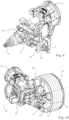
- eine perspektivische Darstellung der Hochdruckpumpe und des Antriebs der Hochdruckpumpe des Hochdruckreinigungsgeräts aus
Fig. 1 , - Fig. 10
- eine perspektivische Darstellung der Hochdruckpumpe, des Antriebs und der Schlauchtrommel der Hochdruckpumpe des Hochdruckreinigungsgeräts aus
Fig. 1 , - Fig. 11
- eine perspektivische Darstellung der Schlauchtrommel und des Trommelschlauchs des Hochdruckreinigungsgeräts aus
Fig. 1 und - Fig. 12
- eine Schnittdarstellung eines Schnitts entlang der abgewinkelten Schnittlinie XII-XII aus
Fig. 2 . -
Fig. 1 zeigt ein Hochdruckreinigungsgerät 1. Das Hochdruckreinigungsgerät 1 ist zur Reinigung von Objekten mit unter Druck gesetzter Reinigungsflüssigkeit ausgelegt. Im Ausführungsbeispiel ist das Hochdruckreinigungsgerät 1 tragbar. Das Hochdruckreinigungsgerät 1 weist einen Handgriff 7 auf. An dem Handgriff 7 ist das Hochdruckreinigungsgerät 1 tragbar. Im bestimmungsgemäßen Betrieb ist vorgesehen, dass das Hochdruckreinigungsgerät 1 abgestellt ist. Das Hochdruckreinigungsgerät 1 ist im Ausführungsbeispiel ein Akkuhochdruckreiniger. - Das Hochdruckreinigungsgerät 1 besitzt ein Gehäuse 2. Das Gehäuse 2 begrenzt das Hochdruckreinigungsgerät 1 zumindest teilweise nach außen hin. Das Hochdruckreinigungsgerät 1 besitzt eine Schlauchtrommel 20. Die Schlauchtrommel 20 ist, wie in den
Fig. 1 bis 4 dargestellt, um eine Drehachse 50 drehbar gelagert. Das Hochdruckreinigungsgerät 1 umfasst einen Trommelschlauch 21. Der Trommelschlauch 21 ist auf die Schlauchtrommel 20 auf- und abwickelbar. Der Trommelschlauch ist auf die Schlauchtrommel 20 auf- und abspulbar. In dem Gehäuse 2 ist eine Hochdruckpumpe 10 angeordnet, die beispielsweise inFig. 4 dargestellt ist. Mittels der Hochdruckpumpe 10 ist Reinigungsflüssigkeit im Hochdruckreinigungsgerät 1 unter Druck setzbar. - Mittels der Hochdruckpumpe 10 kann die Reinigungsflüssigkeit unter einen Druck von mindesten 10 bar, insbesondere von mindestens 15 bar, insbesondere von mindestens 30 bar, insbesondere von mindestens 100 bar gesetzt werden. Insbesondere kann mit der Hochdruckpumpe 10 die Reinigungsflüssigkeit höchstens unter einen Druck von 600 bar, insbesondere von höchstens 500 bar gesetzt werden. Die Hochdruckpumpe 10 umfasst mindestens einen Kolben 11. Der mindestens eine Kolben 11 ist in
Fig. 4 schematisch eingezeichnet. Der mindestens eine Kolben 11 ist zur Erzeugung von Druck auf die Reinigungsflüssigkeit in einer Bewegungsrichtung 49 hin- und herbewegbar. Im Ausführungsbeispiel umfasst die Hochdruckpumpe 10 drei Kolben 11. - Die Hochdruckpumpe besitzt eine in Bewegungsrichtung 49 des mindestens einen Kolbens 11 verlaufende Mittelachse 48. Die Mittelachse 48 ist eine Zentralachse der Hochdruckpumpe 10. Insbesondere ist die Mittelachse 48 der Hochdruckpumpe 10 eine Zentralachse des mindestens einen Kolbens 11. Wenn die Hochdruckpumpe 10 lediglich einen einzigen Kolben 11 umfasst, ist die Mittelachse 48 die Längsmittelachse des Kolbens. Im Ausführungsbeispiel umfasst die Hochdruckpumpe 10 mehrere Kolben 11. In diesem Fall, verläuft die Mittelachse 48 in der Mitte der mehreren Kolben 11. Die Mittelachse 48 ist eine Symmetrieachse bezüglich der Menge aller Kolben 11. Wie in
Fig. 8 dargestellt, können die Kolben 11 auf einer gedachten Kreislinie 17 angeordnet sein. Die gedachte Kreislinie ist inFig. 8 mit gestrichelter Linie eingezeichnet. Die Kolben 11 sind ebenfalls mit gestrichelter Linie schematisch eingezeichnet. Die Mittelachse 48 verläuft durch den Mittelpunkt der Kreislinie 17. Im Ausführungsbeispiel hat die Mittelachse 48 zu allen Kolben 11 denselben Abstand. Dieser Abstand ist senkrecht, insbesondere in Richtung radial zur Bewegungsrichtung 49 des mindestens einen Kolbens 11 gemessen. Es kann aber auch vorgesehen sein, dass die Kolben 11 in einer Reihe angeordnet sind, insbesondere auf einer gedachten Geraden. Die Mittelachse 48 verläuft dann durch die Gerade und teilt die Menge aller Kolben 11 entlang der Geraden in zwei gleich große Hälften. Die Mittelachse 48 liegt dann in der Mitte der Gesamtmenge aus allen Kolben 11. Hierbei kann die Mittelachse 48 auch durch einen der Kolben 11 verlaufen. - Im Ausführungsbeispiel umfasst die Hochdruckpumpe 10 eine Taumelscheibe 12, wie in
Fig. 4 dargestellt. Die Taumelscheibe 12 ist um eine Scheibenrotationsachse 47 drehbar gelagert. Die Taumelscheibe 12 treibt im Betrieb des Hochdruckreinigungsgeräts 1 den mindestens einen Kolben 11 der Hochdruckpumpe 10 an. Die Taumelscheibe 12 rotiert um die Scheibenrotationsachse 47. Hierbei drückt die Taumelscheibe 12 den mindestens einen Kolben 11 in Richtung auf die Reinigungsflüssigkeit. Die Reinigungsflüssigkeit wird hierbei insbesondere in einer nicht dargestellten Kolbenkammer unter Druck gesetzt. Durch die Bewegung des Kolbens 11 in Bewegungsrichtung 49 auf die Reinigungsflüssigkeit zu wird das Volumen der Kolbenkammer verringert. Bei der Bewegung des mindestens einen Kolbens 11 auf die Reinigungsflüssigkeit zu wird ein nicht dargestelltes Rückstellelement, wie beispielsweise eine Feder, gespannt. Aufgrund der Rückstellkraft der Feder wird der mindestens eine Kolben 11 dann wieder in Richtung weg von der Reinigungsflüssigkeit gedrückt. Anschließend sorgt die Taumelscheibe 12 wieder für eine Bewegung des mindestens einen Kolbens 11 in die entgegengesetzte Richtung. Die Taumelscheibe 12 besitzt eine Schrägfläche zur Anlage an dem Kolben 11. Die Schrägfläche verläuft schräg zur Scheibenrotationsachse 47. Die Mittelachse 48 der Hochdruckpumpe 10 verläuft koaxial zur Scheibenrotationsachse 47 der Taumelscheibe 12. Im Betrieb des Hochdruckreinigungsgeräts 1 ist Reinigungsflüssigkeit mittels der Hochdruckpumpe 10 zu dem Trommelschlauch 21 förderbar. - Die Hochdruckpumpe 10 besitzt ein nicht dargestelltes Einlassventil. Durch das Einlassventil kann die Reinigungsflüssigkeit in die Kolbenkammer eintreten. Im Ausführungsbeispiel ist für jeden Kolben 11 ein Einlassventil vorgesehen. Das Einlassventil ist ein Rückschlagventil. Wenn die Reinigungsflüssigkeit in der Kolbenkammer unter Druck gesetzt wird, schließt das Einlassventil.
- Die Hochdruckpumpe 10 besitzt ein nicht dargestelltes Auslassventil. Durch das Auslassventil kann die Reinigungsflüssigkeit aus der Kolbenkammer austreten, und insbesondere in Richtung zum Trommelschlauch 21 hin weiterfließen. Im Ausführungsbeispiel ist für jeden Kolben 11 ein Auslassventil vorgesehen. Das Auslassventil ist ein Rückschlagventil. Es verhindert ein Zurückfließen vom Trommelschlauch 21 in die Kolbenkammer.
- Wie insbesondere in
Fig. 4 dargestellt, verläuft die Drehachse 50 der Schlauchtrommel 20 quer zur Bewegungsrichtung 40 des mindestens einen Kolbens 11. Insbesondere verläuft die Drehachse 50 senkrecht zur Bewegungsrichtung 49 des mindestens einen Kolbens 11. Die Drehachse 50 der Schlauchtrommel 20 schneidet die Hochdruckpumpe 10. - Die Hochdruckpumpe 10 umfasst einen Grundkörper 13. Im Grundkörper 13 ist der mindestens eine Kolben 11 angeordnet. Die Hochdruckpumpe 10 umfasst den mindestens einen Kolben 11. Jedem Kolben 11 ist eine Kolbenkammer zugeordnet, in der die Reinigungsflüssigkeit unter Druck setzbar ist. Jeder Kolbenkammer ist ein nicht dargestelltes Einlassventil zugeordnet. Jeder Kolbenkammer ist ein nicht dargestelltes Auslassventil zugeordnet. Das Einlassventil ist Bestandteil der Hochdruckpumpe 10. Das Auslassventil ist Bestandteil der Hochdruckpumpe 10. Die Kolbenkammer ist Bestandteil der Hochdruckpumpe 10. Das Einlassventil ist im Grundkörper 13 gehalten. Das Auslassventil ist im Grundkörper 13 gehalten. Das Bauteil, das die Hin- und Herbewegung des mindestens einen Kolbens 11 in Bewegungsrichtung 49 bewirkt, ist Bestandteil der Hochdruckpumpe 10. Im Ausführungsbeispiel ist die Taumelscheibe 12 Bestandteil der Hochdruckpumpe 10. Es kann auch vorgesehen sein, dass die Hin- und Herbewegung des mindestens einen Kolbens 11 durch eine Kurbelwelle bewirkt wird. In diesem Fall ist die Kurbelwelle Bestandteil der Hochdruckpumpe 10. Zur Taumelscheibe 12 ist eine Welle 14 zu zählen. Die Hochdruckpumpe 10 umfasst ein Wellengehäuse 15. Die Welle 15 ist im selben Gehäuse 15 drehbar gelagert. Falls der mindestens eine Kolben 11 durch eine Kurbelwelle zur Hin- und Herbewegung in Bewegungsrichtung 49 angetrieben wird, ist die Kurbelwelle im Wellengehäuse 15 drehbar gelagert.
- Das Hochdruckreinigungsgerät 1 umfasst einen Antrieb 5. Der Antrieb 5 dient zum Antrieb der Hochdruckpumpe 10. Der Antrieb 5 ist nicht Bestandteil der Hochdruckpumpe 10. Der Antrieb 5 ist im Ausführungsbeispiel ein Elektromotor. Insbesondere ist der Antrieb 5 ein Gleichstrommotor. Insbesondere ist der Antrieb 5 ein bürstenloser Gleichstrommotor. Der bürstenlose Gleichstrommotor wird auch als EC-Motor bezeichnet.
- Die Hochdruckpumpe 10 umfasst einen Eingangsstutzen 16. Durch den Eingangsstutzen 16 kann Reinigungsflüssigkeit in den Grundkörper 13 der Hochdruckpumpe 10 eintreten. Der Eingangsstutzen 16 ist am Grundkörper 13 festgelegt. Der Eingangsstutzen 16 ist insbesondere unmittelbar am Grundkörper 13 festgelegt. Der Eingangsstutzen 16 ist starr. Der Eingangsstutzen 16 umfasst kein flexibles Element wie beispielsweise einen flexiblen Schlauch. Der Eingangsstutzen 16 ist insbesondere ein Druckgussteil. An den Eingangsstutzen 16 kann ein flexibler Schlauch zur Zuleitung von Reinigungsflüssigkeit angeschlossen werden. Im Ausführungsbeispiel ist hierfür eine Kupplung 8 vorgesehen. Die Kupplung 8 ist nicht Bestandteil der Hochdruckpumpe 10. Auf die Kupplung 8 kann der Schlauch zur Zuleitung der Reinigungsflüssigkeit mittels einer passenden Gegenkupplung aufgesteckt werden. Es kann aber auch vorgesehen sein, dass der Schlauch zur Zuleitung der Reinigungsflüssigkeit mittels einer Schelle oder ähnlichem an dem Eingangsstutzen 16 befestigt ist. Ausgehend vom Eingangsstutzen wird die Reinigungsflüssigkeit dem mindestens einen Einlassventil der Kolbenkammer des mindestens einen Kolbens 11 zugeleitet. Im Ausführungsbeispiel wird die Reinigungsflüssigkeit ausgehend vom Eingangsstutzen 16 mehreren Einlassventilen der mehreren Kolben 11 zugeleitet. Der Eingangsstutzen 16 stellt einen gemeinsamen Einlass von Reinigungsflüssigkeit für alle Kolben 11 der Hochdruckpumpe 10 dar. Der Eingangsstutzen 16 erstreckt sich längs der Bewegungsrichtung 49. Der Eingangsstutzen 16 steht in Bewegungsrichtung 49, in Richtung weg von dem Wellengehäuse 15 über den Grundkörper 13 der Hochdruckpumpe 10 hervor.
- Die Hochdruckpumpe 10 umfasst ein Verbindungselement 30. Das Verbindungselement 30 wird auch als Pumpenausgang der Hochdruckpumpe 10 bezeichnet. Das Verbindungselement 30 stellt einen gemeinsamen Ausgang für die aus den Auslassventilen der mehreren Kolben 11 austretende Reinigungsflüssigkeit dar. Das Verbindungselement 30 ist starr ausgebildet. Das Verbindungselement 30 ist am Grundkörper 13 der Hochdruckpumpe 10 festgelegt. Das Verbindungselement 30 ist insbesondere unmittelbar am Grundkörper 13 der Hochdruckpumpe 10 festgelegt. Das Verbindungselement 30 umfasst keinen flexiblen Schlauch. Im Ausführungsbeispiel ist das Verbindungselement 30 ein Druckgussteil. Das Verbindungselement 30 ist einteilig ausgebildet. Das Verbindungselement 30 erstreckt sich längs einer Richtung, die quer zur Bewegungsrichtung 49, insbesondere senkrecht zur Bewegungsrichtung 49, insbesondere radial zur Mittelachse 48 verläuft.
- Das Hochdruckreinigungsgerät 1 umfasst ein Flüssigkeitsverteilerstück 3. Das Flüssigkeitsverteilerstück 3 verbindet das Verbindungselement 30 unmittelbar mit der Schlauchtrommel 20, insbesondere mit dem Trommelschlauch 21. Die Schlauchtrommel 20 ist drehbar auf dem Flüssigkeitsverteilerstück 3 gelagert. Durch das Flüssigkeitsverteilerstück 3 wird die Reinigungsflüssigkeit in den Trommelschlauch 21 geleitet. Das Flüssigkeitsverteilerstück 3 ist in dem starren Verbindungselement 30 der Hochdruckpumpe 10 gehalten. Das Flüssigkeitsverteilerstück 3 ist starr. Das Flüssigkeitsverteilerstück 3 umfasst keinen flexiblen Schlauch. Das starre Verbindungselement 30 ist unmittelbar mit dem starren Grundkörper 13 der Hochdruckpumpe 20 verbunden. Im Betrieb des Hochdruckreinigungsgeräts 1 kann Reinigungsflüssigkeit von dem Grundkörper 13 der Hochdruckpumpe 10 durch das Verbindungselement 30 der Hochdruckpumpe 10 zu dem Flüssigkeitsverteilerstück 3 fließen. Das Flüssigkeitsverteilerstück 3 ist kein Bestandteil der Hochdruckpumpe 10. Die Hochdruckpumpe 10 umfasst keine flexiblen Zuleitungen oder Ableitungen für Reinigungsflüssigkeit, beispielsweise in Form von Schläuchen.
- Im Ausführungsbeispiel ist die Schlauchtrommel 20 relativ zu der Hochdruckpumpe 10 so angeordnet, dass die Drehachse 50 der Schlauchtrommel 20 die Mittelachse 48 der Hochdruckpumpe 10 schneidet. Insbesondere sind die Drehachse 50 der Schlauchtrommel 20 und die Mittelachse 48 der Hochdruckpumpe 10 senkrecht zueinander orientiert. Die Drehachse 50 der Schlauchtrommel 20 verläuft insbesondere radial zur Mittelachse 48 der Hochdruckpumpe 10.
- Wenn das Hochdruckreinigungsgerät 1 mit einer dafür vorgesehenen Abstellfläche auf einer Horizontalebene abgestellt ist, verläuft die Drehachse 50 der Schlauchtrommel 20 im Ausführungsbeispiel parallel zur Horizontalebene. Wenn das Hochdruckreinigungsgerät 1 mit der dafür vorgesehenen Abstellfläche auf der Horizontalebene abgestellt ist, verläuft die Mittelachse 48 parallel zur Horizontalebene.
- Wie in
Fig. 11 dargestellt, umfasst die Schlauchtrommel 20 eine erste Bordseitenwand 24. Die Schlauchtrommel 20 umfasst eine zweite Bordseitenwand 25. Die erste Bordseitenwand 24 ist in Richtung der Drehachse 50 der Schlauchtrommel 20 von der zweiten Bordseitenwand 25 beabstandet. Zwischen den Bordseitenwänden 24 und 25 ist ein Aufnahmeraum für den Trommelschlauch 21 ausgebildet. Zwischen den Bordseitenwänden 24 und 25 ist der Trommelschlauch 21 aufgewickelt bzw. aufgespult. Wie in der perspektivischen Darstellung ausFig. 10 zu erkennen, ist die erste Bordseitenwand 24 näher zur Hochdruckpumpe 10 angeordnet als die zweite Bordseitenwand 25. Die erste Bordseitenwand 24 ist innen liegend. Die erste Bordseitenwand 24 ist der Hochdruckpumpe 10 zugewandt. - Das Flüssigkeitsverteilerstück 3 ist bezüglich der Richtung der Drehachse 50 näher zur zweiten Bordseitenwand 25 als zur ersten Bordseitenwand 24 angeordnet. Das Flüssigkeitsverteilerstück 3 ist bezüglich der Richtung der Drehachse 50 insbesondere im Bereich der zweiten Bordseitenwand 24 angeordnet.
- Wie in den
Fig. 4 ,8 und12 dargestellt, weist die Schlauchtrommel 20 einen in Richtung der Drehachse 50 der Schlauchtrommel 20 gemessenen Trommelabstand a zu der Mittelachse 48 der Hochdruckpumpe 10 auf. Insbesondere entspricht der Trommelabstand a zwischen der Schlauchtrommel 20 und der Mittelachse 48 dem in Richtung der Drehachse 50 gemessenen Abstand zwischen der Mittelachse 48 und der ersten Bordseitenwand 24. Zu der Schlauchtrommel 20 zählen nur die Teile, die um die Drehachse 50 drehbar sind. - Wie in den
Fig. 4 und8 dargestellt, weist das Hochdruckreinigungsgerät 1 eine in Richtung der Drehachse 50 der Schlauchtrommel 20 gemessene maximale Breite b auf. Bei der Bestimmung der maximalen Breite b werden sämtliche Bauteile des Hochdruckreinigungsgeräts 1 berücksichtigt. Der Trommelabstand a beträgt höchstens 50%, insbesondere höchstens 40%, im Ausführungsbeispiel höchstens 30% der maximalen Breite b. Der Trommelabstand a beträgt mindestens 10%, im Ausführungsbeispiel mindestens 20% der maximalen Breite b. - Wie in den
Fig. 4 dargestellt, weist das Gehäuse 2 eine in Richtung der Drehachse 50 der Schlauchtrommel 20 gemessene maximale Innenbreite h auf. Der Trommelabstand a beträgt höchstens 50%, im Ausführungsbeispiel höchstens 40% der maximalen Innenbreite h. Der Trommelabstand a beträgt mindestens 20%, im Ausführungsbeispiel mindestens 30% der maximalen Innenbreite h. - Die Schlauchtrommel 20 besitzt eine in den
Fig. 4 und8 dargestellte, in Richtung der Drehachse 50 der Schlauchtrommel 20 gemessene Trommelbreite c. Bei der Bestimmung der Trommelbreite c werden sämtliche Bauteile der Schlauchtrommel 20 berücksichtigt. Wie inFig. 1 dargestellt, umfasst die Schlauchtrommel 20 einen Kurbelzapfen 26. Der Kurbelzapfen 26 ist Bestandteil der Schlauchtrommel 20. Der Kurbelzapfen 26 ist bei Ermittlung der Trommelbreite c mit zu berücksichtigen. Die Trommelbreite c ist im Ausführungsbeispiel von der der Hochdruckpumpe 10 zugewandten Seite der ersten Bordseitenwand 24 bis zu dem außen liegenden Längsende des Kurbelzapfens 26 gemessen. - Der Trommelabstand a beträgt höchstens 70%, insbesondere höchstens 60%, im Ausführungsbeispiel höchstens 55% der Trommelbreite c.
- Die Trommelbreite c beträgt höchstens 60%, im Ausführungsbeispiel höchstens 50% der maximalen Breite b des Hochdruckreinigungsgeräts 1.
- Die Trommelbreite c beträgt mindestens 30%, im Ausführungsbeispiel mindestens 40% der maximalen Breite b des Hochdruckreinigungsgeräts 1.
- Die Trommelbreite c beträgt höchstens 80%, im Ausführungsbeispiel höchstens 70% der maximalen Innenbreite h des Gehäuses 2.
- Die Trommelbreite c beträgt mindestens 40%, im Ausführungsbeispiel mindestens 50% der maximalen Innenbreite h des Gehäuses 2.
- Die Hochdruckpumpe 10 besitzt eine in Richtung der Drehachse 50 der Schlauchtrommel 20 gemessene Pumpenbreite e. Dies ist in den
Fig. 4 und8 dargestellt. Die Pumpenbreite e der Hochdruckpumpe 10 beträgt mindestens 40%, im Ausführungsbeispiel mindestens 50% der maximalen Breite b des Hochdruckreinigungsgeräts 1. Die Pumpenbreite e beträgt höchstens70%, im Ausführungsbeispiel höchstens 60% der maximalen Breite b. - Die Pumpenbreite e der Hochdruckpumpe 10 beträgt mindestens 70%, im Ausführungsbeispiel mindestens 80% der maximalen Innenbreite h des Gehäuses 2 des Hochdruckreinigungsgeräts 1. Die Pumpenbreite e beträgt höchstens95%, im Ausführungsbeispiel höchstens 90% der maximalen Innenbreite h.
- Das Verbindungselement 30 besitzt eine in Richtung der Drehachse 50 der Schlauchtrommel 20 gemessene Verbindungsbreite f, wie in den
Fig. 4 und8 dargestellt. Die Verbindungsbreite f beträgt mindestens 15%, im Ausführungsbeispiel mindestens 25% der maximalen Breite b des Hochdruckreinigungsgeräts 1. Die Verbindungsbreite f beträgt höchstens 45%, im Ausführungsbeispiel höchstens 35% der maximalen Breite b des Hochdruckreinigungsgeräts 1. - Wie insbesondere in den
Fig. 4 und8 dargestellt, ist zwischen dem Flüssigkeitsverteilerstück 3 und der Hochdruckpumpe 10, insbesondere zwischen dem Flüssigkeitsverteilerstück 3 und dem Grundkörper 13 der Hochdruckpumpe 10, kein flexibles Leitungsstück, insbesondere kein flexibler Schlauch angeordnet. Diese Aussage bezieht sich auf die Bauteile des Hochdruckreinigungsgeräts 1, die an der Leitung der Reinigungsflüssigkeit von der Hochdruckpumpe 10 zu dem Flüssigkeitsverteilerstück 3 beteiligt sind. Sämtliche dieser Bauteile sind starr ausgebildet. Im Ausführungsbeispiel sind sämtliche dieser Bauteile - mit Ausnahme von Dichtringen und Schrauben - Druckgussbauteile. - Das Verbindungselement 30 ragt in Richtung der Drehachse 50 in die Schlauchtrommel 20 ein. Bezüglich der Richtung der Drehachse 50 der Schlauchtrommel 20 überlappen sich die Hochdruckpumpe 10, insbesondere das Verbindungselement 30, und die Schlauchtrommel 20. Die Schlauchtrommel 20 übergreift die Hochdruckpumpe 10, insbesondere das Verbindungselement 30 der Hochdruckpumpe 10. Die Hochdruckpumpe 10, insbesondere das Verbindungselement 30, überlappt die Schlauchtrommel 20 bezüglich der Richtung der Drehachse 50 über mindestens 30% der Trommelbreite c.
- Die Schlauchtrommel 20 weist an ihrer der Hochdruckpumpe 10 zugewandten inneren Außenseite 22 einen Aufnahmeraum 23 auf. Dies ist insbesondere in den
Fig. 10 und11 dargestellt. Die innere Außenseite 22 ist von der ersten Bordwand 22 ausgebildet. Die innere Außenseite 22 ist eine Außenseite der ersten Bordwand 24. Der Aufnahmeraum 23 liegt bezüglich der Drehachse 50 radial innen. Dies ist auch in denFig. 4 und8 ersichtlich. Der Aufnahmeraum 23 ist im Ausführungsbeispiel zur Aufnahme einer Reinigungszuführleitung 32 ausgelegt. Die Reinigungszuführleitung 32 dient zur Beimischung von Reinigungsmittel zu der Reinigungsflüssigkeit. Die Reinigungszuführleitung 32 ist in denFig. 8 und10 dargestellt. Die Reinigungszuführleitung 32 ist kein Bestandteil des Verbindungselements 30. Die Reinigungszuführleitung 32 ist kein Bestandteil der Hochdruckpumpe 10. - Wie in
Fig. 4 dargestellt, besitzt der Aufnahmeraum 23 einen in Richtung senkrecht zur Drehachse 50 gemessenen maximalen Durchmesser d1. Das Flüssigkeitsverteilerstück 3 besitzt einen in Richtung senkrecht zur Drehachse gemessenen Durchmesser d2. Der Durchmesser d2 ist der Außendurchmesser des Flüssigkeitsverteilerstücks 3. Der maximale Durchmesser d1 des Aufnahmeraums 23 ist größer als der Durchmesser d2 des Flüssigkeitsverteilerstücks 3. Die Hochdruckpumpe 10, insbesondere das Verbindungselement 30, besitzt eine Reinigungszuführöffnung 31, wie inFig. 8 dargestellt. Die Reinigungszuführöffnung 31 dient zur Beimischung von Reinigungsmittel zu der Reinigungsflüssigkeit. Durch die Reinigungszuführöffnung 31 kann Reinigungsmittel in die Hochdruckpumpe 10, insbesondere in das Verbindungselement 30 eingeführt werden. Die Reinigungszuführöffnung 31 ist bezüglich der Richtung der Drehachse 30 der Schlauchtrommel 20 im Bereich der Schlauchtrommel 20 angeordnet. Die Schlauchtrommel 20 übergreift die Reinigungszuführöffnung 31. Es kann vorgesehen sein, dass die Reinigungszuführöffnung 31 im Bereich einer Querschnittsverengung für die Reinigungsflüssigkeit angeordnet ist. Dieser Bereich wird als Venturidüse bezeichnet. - Wie insbesondere
Fig. 4 zu entnehmen, überlappen sich die Schlauchtrommel 20 und die Hochdruckpumpe 10 bezüglich der Bewegungsrichtung 49. Im Ausführungsbeispiel überlappt die Schlauchtrommel 20 die Hochdruckpumpe 10 bezüglich der Bewegungsrichtung 49 vollständig. Die Hochdruckpumpe 10 ist bezüglich der Bewegungsrichtung 49 vollständig im Bereich der Schlauchtrommel 20 angeordnet. - Bezüglich der Richtung der Drehachse 50 der Schlauchtrommel 20 sind die Schlauchtrommel 20 und die Hochdruckpumpe 10 hintereinander angeordnet. In Bewegungsrichtung 49 gesehen liegen die Hochdruckpumpe 10 und die Schlauchtrommel 20 nebeneinander.
- Das Hochdruckreinigungsgerät 1 umfasst einen Akkupack 4. Der Akkupack ist in den
Fig. 4 bis 7 dargestellt. Der Akkupack 4 dient zur Energieversorgung des Antriebs 5 der Hochdruckpumpe 10. Wie ebenfalls in denFig. 4 bis 7 dargestellt, umfasst das Hochdruckreinigungsgerät 1 einen Akkuschacht 6. Der Akkuschacht 6 dient zur Aufnahme des Akkupacks 4. Der Akkupack 4 ist durch eine Schachtöffnung des Akkuschachts 6 hindurch in den Akkuschacht 6 einführbar. Die Schachtöffnung läuft geschlossen um die Einführrichtung des Akkupacks 4 um. Im Ausführungsbeispiel ist der Akkuschacht 6 im Gehäuse 2 angeordnet. Im Ausführungsbeispiel ist der Akkupack 4 im Gehäuse 2 angeordnet. Wie inFig. 4 dargestellt, überlappen sich der Akkuschacht 6 und die Schlauchtrommel 20 bezüglich der Richtung der Drehachse 50 der Schlauchtrommel 20 zumindest teilweise. Der Akkuschacht 6 und die Hochdruckpumpe 10 überlappen sich bezüglich der Richtung der Drehachse 50 der Schlauchtrommel 20 zumindest teilweise. In Bewegungsrichtung gesehen überlappt der Akkuschacht 6 sowohl die Hochdruckpumpe10 als auch die Schlauchtrommel 20. Bezüglich der Bewegungsrichtung 49 sind der Akkuschacht 6 und die Hochdruckpumpe 10 hintereinander angeordnet. Bezüglich der Bewegungsrichtung 49 sind der Akkuschacht 6 und die Schlauchtrommel 20 hintereinander angeordnet. Bezüglich der Bewegungsrichtung 49 ist der Antrieb 5 zwischen dem Akkuschacht 6 und der Hochdruckpumpe 10 angeordnet. Der Antrieb 5 ist in dem Gehäuse 2 angeordnet. Die Hochdruckpumpe 10 ist in dem Gehäuse 2 angeordnet. Die Hochdruckpumpe 10, der Antrieb 5 für die Hochdruckpumpe 10 und der Akkuschacht 6 sind bezüglich der Richtung der Mittelachse 48, insbesondere bezüglich der Bewegungsrichtung 49 hintereinander angeordnet. - Wie insbesondere in den
Fig. 1 bis 3 erkennbar, bildet die Schlauchtrommel 20 einen Teil der Außenkontur des Hochdruckreinigungsgeräts 1. Insbesondere bildet die zweite Bordseitenwand 25 einen Teil der Außenkontur des Hochdruckreinigungsgeräts 1. Insbesondere bildet der Trommelschlauch 21 einen Teil der Außenkontur des Hochdruckreinigungsgeräts 1. Im Ausführungsbeispiel setzt die Schlauchtrommel 20, insbesondere die zweite Bordseitenwand 25 die Außenkontur des Gehäuses 2 des Hochdruckreinigungsgeräts 1 fort. - Die Schlauchtrommel 20 ist im Ausführungsbeispiel außerhalb des Gehäuses 2 angeordnet.
- Die zweite Bordseitenwand 25 ist der Hochdruckpumpe 10 abgewandt.
- Wie in
Fig. 4 dargestellt, steht die Schlauchtrommel 20 in Richtung der Drehachse 50 der Schlauchtrommel 20 mit weniger als 35% ihrer Trommelbreite c über die Außenkontur des Gehäuses 2 hervor. - Die Schlauchtrommel 20 besitzt eine Bordseitenbreite g. Die Bordseitenbreite g ist in
Fig. 4 eingezeichnet. Die Bordseitenbreite g ist in Richtung der Drehachse 50 der Schlauchtrommel 20 gemessen. Die Bordseitenbreite g entspricht dem größten Abstand der Außenseiten der Bordseitenwände 24 und 25 zueinander. Der Kurbelzapfen 26 zählt nicht zur zweiten Bordseitenwand 25 dazu. Eine an der zweiten Bordseitenwand 25 vorgesehene Halterung der zweiten Bordseitenwand 25 zählt bei der Bestimmung der Bordseitenbreite g nicht zu der zweiten Bordseitenwand 25 dazu. Die zweite Bordseitenwand 25 steht in Richtung der Drehachse 50 der Schlauchtrommel 20 um weniger als 10%, im Ausführungsbeispiel um weniger als 5% der Bordseitenbreite g über die Außenkontur des Gehäuses 2 hervor. - Wie den
Fig. 1 und4 zu entnehmen, ist durch das Gehäuse 2 eine Aufnahme 9 für die Schlauchtrommel 20 gebildet. Die Aufnahme 9 übergreift die Schlauchtrommel 20 an ihrer Umfangsseite zumindest teilweise. Die Aufnahme 9 ist durch ein erstes Gehäusebauteil des Gehäuses 2 gebildet. Das erste Gehäusebauteil ist mit einem zweiten Gehäusebauteil des Gehäuses 2 zu einer Einheit verbunden.
Claims (15)
- Hochdruckreinigungsgerät umfassend:- eine Hochdruckpumpe (10) mittels derer Reinigungsflüssigkeit im Hochdruckreinigungsgerät (1) unter Druck setzbar ist,- eine Schlauchtrommel (20), die um eine Drehachse (50) drehbar gelagert ist,- einen Trommelschlauch (21), der auf die Schlauchtrommel (20) auf- und abwickelbar ist und- ein Gehäuse (2),wobei die Hochruckpumpe (10) in dem Gehäuse (2) angeordnet ist, wobei die Hochdruckpumpe (10) mindestens einen Kolben (11) umfasst, der zur Erzeugung von Druck auf die Reinigungsflüssigkeit in einer Bewegungsrichtung (49) hin- und her bewegbar ist, wobei die Hochdruckpumpe (10) eine in Bewegungsrichtung (49) des mindestens einen Kolbens (11) verlaufende Mittelachse (48) besitzt, wobei im Betrieb des Hochdruckreinigungsgeräts (1) Reinigungsflüssigkeit mittels der Hochdruckpumpe (10) zu dem Trommelschlauch (21) förderbar ist,dadurch gekennzeichnet, dass die Drehachse (50) quer zur Bewegungsrichtung (49) des mindestens einen Kolbens (11) verläuft, und dass die Drehachse (50) die Hochdruckpumpe (10) schneidet.
- Hochdruckreinigungsgerät nach Anspruch 1,
dadurch gekennzeichnet, dass die Drehachse (50) der Schlauchtrommel (20) die Mittelachse (48) der Hochdruckpumpe (10) schneidet, insbesondere dass die Drehachse (50) der Schlauchtrommel (20) und die Mittelachse (48) der Hochdruckpumpe (10) senkrecht zueinander orientiert sind. - Hochdruckreinigungsgerät nach Anspruch 1 oder 2,
dadurch gekennzeichnet, dass die Schlauchtrommel (20) einen in Richtung der Drehachse (50) der Schlautrommel (20) gemessenen Trommelabstand (a) zu der Mittelachse (48) aufweist, dass das Hochdruckreinigungsgerät (1) eine in Richtung der Drehachse (50) gemessene maximale Breite (b) aufweist, und dass der Trommelabstand (a) höchstens 50%, insbesondere höchstens 40%, insbesondere höchstens 30% der maximalen Breite (b) beträgt. - Hochdruckreinigungsgerät nach einem der Ansprüche 1 bis 3,
dadurch gekennzeichnet, dass die Schlauchtrommel (20) eine in Richtung der Drehachse (50) gemessene Trommelbreite (c) besitzt, und dass der Trommelabstand (a) höchstens 70%, insbesondere höchstens 60%, insbesondere höchstens 55%, der Trommelbreite (c) beträgt. - Hochdruckreinigungsgerät nach einem der Ansprüche 1 bis 4,
dadurch gekennzeichnet, dass die Trommelbreite (c) höchsten 60%, insbesondere höchstens 50% der maximalen Breite (b) des Hochdruckreinigungsgeräts (1) beträgt. - Hochdruckreinigungsgerät nach einem der Ansprüche 1 bis 5,
dadurch gekennzeichnet, dass die Schlauchtrommel (20) auf einem Flüssigkeitsverteilerstück (3) drehbar gelagert ist, dass das Flüssigkeitsverteilerstück (3) in einem starren Verbindungselement (30) gehalten ist, dass das starre Verbindungselement (30) unmittelbar mit einem starren Grundkörper (13) der Hochdruckpumpe (10) verbunden ist, und dass im Betrieb des Hochdruckreinigungsgeräts (1) Reinigungsflüssigkeit von dem Grundkörper (13) durch das Verbindungselement (30) zu dem Flüssigkeitsverteilerstück (3) fließen kann. - Hochdruckreinigungsgerät nach einem der Ansprüche 1 bis 6,
dadurch gekennzeichnet, dass zwischen dem Flüssigkeitsverteilerstück (3) und der Hochdruckpumpe (10), insbesondere zwischen dem Flüssigkeitsverteilerstück (3) und dem Grundkörper (13) der Hochdruckpumpe (10), kein flexibles Leitungsstück, insbesondere kein flexibler Schlauch angeordnet ist. - Hochdruckreinigungsgerät nach einem der Ansprüche 1 bis 7,
dadurch gekennzeichnet, dass das die Hochdruckpumpe (10), insbesondere das Verbindungselement (30) der Hochdruckpumpe (10), in Richtung der Drehachse (50) in die Schlauchtrommel (20) einragt. - Hochdruckreinigungsgerät nach Anspruch 8,
dadurch gekennzeichnet, dass das die Hochdruckpumpe (10), insbesondere das Verbindungselement (30) der Hochdruckpumpe (10), die Schlauchtrommel (20) bezüglich der Richtung der Drehachse (50) über mindestens 30% der Trommelbreite (c) überlappt. - Hochdruckreinigungsgerät nach einem der Ansprüche 1 bis 9,
dadurch gekennzeichnet, dass die Schlauchtrommel (20) an ihrer der Hochdruckpumpe (10) zugewandten inneren Außenseite (22) einen bezüglich der Drehachse (50) radial innenliegenden Aufnahmeraum (23) aufweist, und insbesondere dass der Aufnahmeraum (23) zur Aufnahme einer Reinigungszuführleitung (32) zur Beimischung von Reinigungsmittel zu der Reinigungsflüssigkeit ausgelegt ist. - Hochdruckreinigungsgerät nach Anspruch 10,
dadurch gekennzeichnet, dass der Aufnahmeraum (23) einen in Richtung senkrecht zur Drehachse (50) gemessenen maximalen Durchmesser (d1) besitzt, und dass der maximale Durchmesser (d1) größer als ein in Richtung senkrecht zur Drehachse (50) gemessener Durchmesser (d2) des Flüssigkeitsverteilerstrücks (3) ist. - Hochdruckreinigungsgerät nach einem der Ansprüche 7 bis 11,
dadurch gekennzeichnet, dass das Verbindungselement (30) eine Reinigungszuführöffnung (31) zur Beimischung von Reinigungsmittel zu der Reinigungsflüssigkeit umfasst, und insbesondere dass die Reinigungszuführöffnung (31) bezüglich der Richtung der Drehachse (50) im Bereich der Schlauchtrommel (20) angeordnet ist. - Hochdruckreinigungsgerät nach einem der Ansprüche 1 bis 12,
dadurch gekennzeichnet, dass das Hochdruckreinigungsgerät (1) einen Akkupack (4) zur Energieversorgung eines Antriebs (5) der Hochdruckpumpe (10) umfasst, dass das Hochdruckreinigungsgerät (1) einen Akkuschacht (6) zur Aufnahme des Akkupacks (4) aufweist, und dass der Akkuschacht (6) und die Schlauchtrommel (20) einander bezüglich der Richtung der Drehachse (50) zumindest teilweise überlappen, und insbesondere dass der Akkuschacht (6) und die Hochdruckpumpe (10) einander bezüglich der Richtung der Drehachse (50) zumindest teilweise überlappen. - Hochdruckreinigungsgerät nach einem der Ansprüche 1 bis 13,
dadurch gekennzeichnet, dass die Hochdruckpumpe (10), ein Antrieb (5) für die Hochdruckpumpe (10) und der Akkuschacht (6) bezüglich der Richtung der Mittelachse (48) hintereinander angeordnet sind. - Hochdruckreinigungsgerät nach einem der Ansprüche 1 bis 14,
dadurch gekennzeichnet, dass die Schlauchtrommel (20) einen Teil der Außenkontur des Hochdruckreinigungsgeräts (1) bildet, und insbesondere dass die Schlauchtrommel (20) in Richtung der Drehachse (50) mit weniger als 35% ihrer Trommelbreite (c) über eine Außenkontur des Gehäuses (2) hervorsteht.
Priority Applications (3)
| Application Number | Priority Date | Filing Date | Title |
|---|---|---|---|
| EP23189259.7A EP4502377A1 (de) | 2023-08-02 | 2023-08-02 | Hochdruckreinigungsgerät |
| US18/790,202 US20250041907A1 (en) | 2023-08-02 | 2024-07-31 | Pressure washer |
| CN202411049608.3A CN119426236A (zh) | 2023-08-02 | 2024-08-01 | 高压清洁器具 |
Applications Claiming Priority (1)
| Application Number | Priority Date | Filing Date | Title |
|---|---|---|---|
| EP23189259.7A EP4502377A1 (de) | 2023-08-02 | 2023-08-02 | Hochdruckreinigungsgerät |
Publications (1)
| Publication Number | Publication Date |
|---|---|
| EP4502377A1 true EP4502377A1 (de) | 2025-02-05 |
Family
ID=87555005
Family Applications (1)
| Application Number | Title | Priority Date | Filing Date |
|---|---|---|---|
| EP23189259.7A Pending EP4502377A1 (de) | 2023-08-02 | 2023-08-02 | Hochdruckreinigungsgerät |
Country Status (3)
| Country | Link |
|---|---|
| US (1) | US20250041907A1 (de) |
| EP (1) | EP4502377A1 (de) |
| CN (1) | CN119426236A (de) |
Citations (3)
| Publication number | Priority date | Publication date | Assignee | Title |
|---|---|---|---|---|
| US8439651B2 (en) * | 2009-07-14 | 2013-05-14 | Briggs & Stratton Corporation | Garden hose booster water pump system |
| US20190072085A1 (en) * | 2017-09-06 | 2019-03-07 | Allan Schultz | Portable solar powered fluid dispenser for release agents |
| US10626857B1 (en) * | 2016-09-13 | 2020-04-21 | Jeffrey Hale Suntup | Apparatus for dispensing small quantities of heating oil |
Family Cites Families (3)
| Publication number | Priority date | Publication date | Assignee | Title |
|---|---|---|---|---|
| JP2006525869A (ja) * | 2003-04-11 | 2006-11-16 | グレート スタッフ インコーポレイテッド | 空気/液体のための流体制御システム |
| US8485203B2 (en) * | 2010-05-09 | 2013-07-16 | Edward Michael Kubasiewicz | Surface cleaning with concurrently usable prespray and rinse units |
| US20140352807A1 (en) * | 2013-05-31 | 2014-12-04 | Active Products Inc. | Pressure washer with hose reel and motor pump assembly |
-
2023
- 2023-08-02 EP EP23189259.7A patent/EP4502377A1/de active Pending
-
2024
- 2024-07-31 US US18/790,202 patent/US20250041907A1/en active Pending
- 2024-08-01 CN CN202411049608.3A patent/CN119426236A/zh active Pending
Patent Citations (3)
| Publication number | Priority date | Publication date | Assignee | Title |
|---|---|---|---|---|
| US8439651B2 (en) * | 2009-07-14 | 2013-05-14 | Briggs & Stratton Corporation | Garden hose booster water pump system |
| US10626857B1 (en) * | 2016-09-13 | 2020-04-21 | Jeffrey Hale Suntup | Apparatus for dispensing small quantities of heating oil |
| US20190072085A1 (en) * | 2017-09-06 | 2019-03-07 | Allan Schultz | Portable solar powered fluid dispenser for release agents |
Also Published As
| Publication number | Publication date |
|---|---|
| CN119426236A (zh) | 2025-02-14 |
| US20250041907A1 (en) | 2025-02-06 |
Similar Documents
| Publication | Publication Date | Title |
|---|---|---|
| DE69330002T2 (de) | Peristaltische pumpe | |
| DE4020029A1 (de) | Mundhygiene-einrichtung | |
| DE60119842T2 (de) | Hydraulisches Handwerkzeug mit ringförmigem Behälter | |
| DE112009002029T5 (de) | Flügelzellen-Pumpenvorrichtung | |
| DE2736153A1 (de) | Filter- und mischeinrichtung zur vermischung von schmieroel und kraftstoff | |
| DE102006005553B4 (de) | Doppel-Getriebefilterkonstruktion | |
| DE4025225A1 (de) | Vergaser-oelpumpen-anordnung und verfahren fuer deren herstellung | |
| EP1194694B2 (de) | Vorrichtung zum pumpen grosser fördermengen einer flüssigkeit | |
| DE112018007960T5 (de) | Waschmittelkartusche und Haushaltsgerät | |
| DE1528540B2 (de) | Steuerung für einen hydraulischen Radialkolbenmotor | |
| DE3919594A1 (de) | Zweitakt-brennkraftmaschine mit fremdschmierung | |
| CH673886A5 (de) | ||
| DE2556654A1 (de) | Fluessigkeitspumpe | |
| DE19962798C2 (de) | Spiralverdichter oder Spiralpumpe | |
| EP0499347B1 (de) | Zentralschmieraggregat | |
| EP0099000B1 (de) | Kolbenmaschine mit sternförmig angeordneten Zylindern | |
| EP2179138A2 (de) | Verdrängermaschine nach dem spiralprinzip mit beidseitiger lageranordnung | |
| DE102024108427B4 (de) | Definierter Wasserzulauf für Ansaugkammer | |
| DE563101C (de) | Zahnradspinnpumpe fuer Kunstseidespinnmaschinen | |
| DE10140876A1 (de) | Ölpumpenaufbau bei einem Motor | |
| DE10254840A1 (de) | Pumpenanordnung mit einer Hochdruckpumpe und einer dieser vorgeschalteten Niederdruckpumpe für eine Kraftstoffeinspritzeinrichtung einer Brennkraftmaschine | |
| DE2150070A1 (de) | Fluessigkeits-Zuteilvorrichtung | |
| DE1849591U (de) | Hydraulische pumpe. | |
| DE2404391A1 (de) | Kraftstoff-einspritzvorrichtung fuer eine verbrennungskraftmaschine | |
| DE102010016412A1 (de) | Vorrichtungsmodul zum Austragen von Schmiermittel aus einer Düse |
Legal Events
| Date | Code | Title | Description |
|---|---|---|---|
| PUAI | Public reference made under article 153(3) epc to a published international application that has entered the european phase |
Free format text: ORIGINAL CODE: 0009012 |
|
| STAA | Information on the status of an ep patent application or granted ep patent |
Free format text: STATUS: THE APPLICATION HAS BEEN PUBLISHED |
|
| AK | Designated contracting states |
Kind code of ref document: A1 Designated state(s): AL AT BE BG CH CY CZ DE DK EE ES FI FR GB GR HR HU IE IS IT LI LT LU LV MC ME MK MT NL NO PL PT RO RS SE SI SK SM TR |
|
| STAA | Information on the status of an ep patent application or granted ep patent |
Free format text: STATUS: REQUEST FOR EXAMINATION WAS MADE |
|
| GRAP | Despatch of communication of intention to grant a patent |
Free format text: ORIGINAL CODE: EPIDOSNIGR1 |
|
| STAA | Information on the status of an ep patent application or granted ep patent |
Free format text: STATUS: GRANT OF PATENT IS INTENDED |
|
| 17P | Request for examination filed |
Effective date: 20250730 |
|
| INTG | Intention to grant announced |
Effective date: 20250902 |
|
| GRAS | Grant fee paid |
Free format text: ORIGINAL CODE: EPIDOSNIGR3 |
|
| GRAJ | Information related to disapproval of communication of intention to grant by the applicant or resumption of examination proceedings by the epo deleted |
Free format text: ORIGINAL CODE: EPIDOSDIGR1 |
|
| GRAL | Information related to payment of fee for publishing/printing deleted |
Free format text: ORIGINAL CODE: EPIDOSDIGR3 |
|
| STAA | Information on the status of an ep patent application or granted ep patent |
Free format text: STATUS: REQUEST FOR EXAMINATION WAS MADE |
|
| INTC | Intention to grant announced (deleted) | ||
| GRAP | Despatch of communication of intention to grant a patent |
Free format text: ORIGINAL CODE: EPIDOSNIGR1 |
|
| STAA | Information on the status of an ep patent application or granted ep patent |
Free format text: STATUS: GRANT OF PATENT IS INTENDED |
|
| INTG | Intention to grant announced |
Effective date: 20260121 |
|
| GRAJ | Information related to disapproval of communication of intention to grant by the applicant or resumption of examination proceedings by the epo deleted |
Free format text: ORIGINAL CODE: EPIDOSDIGR1 |
|
| GRAL | Information related to payment of fee for publishing/printing deleted |
Free format text: ORIGINAL CODE: EPIDOSDIGR3 |
|
| STAA | Information on the status of an ep patent application or granted ep patent |
Free format text: STATUS: REQUEST FOR EXAMINATION WAS MADE |
|
| INTC | Intention to grant announced (deleted) | ||
| GRAP | Despatch of communication of intention to grant a patent |
Free format text: ORIGINAL CODE: EPIDOSNIGR1 |
|
| STAA | Information on the status of an ep patent application or granted ep patent |
Free format text: STATUS: GRANT OF PATENT IS INTENDED |
|
| INTG | Intention to grant announced |
Effective date: 20260612 |