EP4501751A1 - Fahrzeug - Google Patents
Fahrzeug Download PDFInfo
- Publication number
- EP4501751A1 EP4501751A1 EP23207057.3A EP23207057A EP4501751A1 EP 4501751 A1 EP4501751 A1 EP 4501751A1 EP 23207057 A EP23207057 A EP 23207057A EP 4501751 A1 EP4501751 A1 EP 4501751A1
- Authority
- EP
- European Patent Office
- Prior art keywords
- tube body
- bracket
- pedal
- parking
- rounded
- Prior art date
- Legal status (The legal status is an assumption and is not a legal conclusion. Google has not performed a legal analysis and makes no representation as to the accuracy of the status listed.)
- Pending
Links
- 230000003014 reinforcing effect Effects 0.000 claims description 8
- 230000002787 reinforcement Effects 0.000 description 11
- 238000003780 insertion Methods 0.000 description 7
- 230000037431 insertion Effects 0.000 description 7
- 230000001154 acute effect Effects 0.000 description 2
- 230000007423 decrease Effects 0.000 description 2
- 230000003247 decreasing effect Effects 0.000 description 2
- 230000005540 biological transmission Effects 0.000 description 1
- 230000000694 effects Effects 0.000 description 1
- 238000000034 method Methods 0.000 description 1
- 230000001360 synchronised effect Effects 0.000 description 1
- 230000009466 transformation Effects 0.000 description 1
- 238000000844 transformation Methods 0.000 description 1
Images


Classifications
-
- B—PERFORMING OPERATIONS; TRANSPORTING
- B62—LAND VEHICLES FOR TRAVELLING OTHERWISE THAN ON RAILS
- B62D—MOTOR VEHICLES; TRAILERS
- B62D31/00—Superstructures for passenger vehicles
- B62D31/003—Superstructures for passenger vehicles compact cars, e.g. city cars
- B62D31/006—Superstructures for passenger vehicles compact cars, e.g. city cars foldable
-
- B—PERFORMING OPERATIONS; TRANSPORTING
- B60—VEHICLES IN GENERAL
- B60T—VEHICLE BRAKE CONTROL SYSTEMS OR PARTS THEREOF; BRAKE CONTROL SYSTEMS OR PARTS THEREOF, IN GENERAL; ARRANGEMENT OF BRAKING ELEMENTS ON VEHICLES IN GENERAL; PORTABLE DEVICES FOR PREVENTING UNWANTED MOVEMENT OF VEHICLES; VEHICLE MODIFICATIONS TO FACILITATE COOLING OF BRAKES
- B60T7/00—Brake-action initiating means
- B60T7/02—Brake-action initiating means for personal initiation
- B60T7/04—Brake-action initiating means for personal initiation foot actuated
- B60T7/045—Brake-action initiating means for personal initiation foot actuated with locking and release means, e.g. providing parking brake application
-
- B—PERFORMING OPERATIONS; TRANSPORTING
- B60—VEHICLES IN GENERAL
- B60T—VEHICLE BRAKE CONTROL SYSTEMS OR PARTS THEREOF; BRAKE CONTROL SYSTEMS OR PARTS THEREOF, IN GENERAL; ARRANGEMENT OF BRAKING ELEMENTS ON VEHICLES IN GENERAL; PORTABLE DEVICES FOR PREVENTING UNWANTED MOVEMENT OF VEHICLES; VEHICLE MODIFICATIONS TO FACILITATE COOLING OF BRAKES
- B60T7/00—Brake-action initiating means
- B60T7/02—Brake-action initiating means for personal initiation
- B60T7/04—Brake-action initiating means for personal initiation foot actuated
- B60T7/06—Disposition of pedal
-
- B—PERFORMING OPERATIONS; TRANSPORTING
- B62—LAND VEHICLES FOR TRAVELLING OTHERWISE THAN ON RAILS
- B62D—MOTOR VEHICLES; TRAILERS
- B62D21/00—Understructures, i.e. chassis frame on which a vehicle body may be mounted
- B62D21/14—Understructures, i.e. chassis frame on which a vehicle body may be mounted of adjustable length or width
-
- B—PERFORMING OPERATIONS; TRANSPORTING
- B62—LAND VEHICLES FOR TRAVELLING OTHERWISE THAN ON RAILS
- B62D—MOTOR VEHICLES; TRAILERS
- B62D21/00—Understructures, i.e. chassis frame on which a vehicle body may be mounted
- B62D21/18—Understructures, i.e. chassis frame on which a vehicle body may be mounted characterised by the vehicle type and not provided for in groups B62D21/02 - B62D21/17
- B62D21/183—Understructures, i.e. chassis frame on which a vehicle body may be mounted characterised by the vehicle type and not provided for in groups B62D21/02 - B62D21/17 specially adapted for sports vehicles, e.g. race, dune buggies, go-karts
-
- B—PERFORMING OPERATIONS; TRANSPORTING
- B62—LAND VEHICLES FOR TRAVELLING OTHERWISE THAN ON RAILS
- B62D—MOTOR VEHICLES; TRAILERS
- B62D25/00—Superstructure or monocoque structure sub-units; Parts or details thereof not otherwise provided for
- B62D25/06—Fixed roofs
-
- G—PHYSICS
- G05—CONTROLLING; REGULATING
- G05G—CONTROL DEVICES OR SYSTEMS INSOFAR AS CHARACTERISED BY MECHANICAL FEATURES ONLY
- G05G1/00—Controlling members, e.g. knobs or handles; Assemblies or arrangements thereof; Indicating position of controlling members
- G05G1/01—Arrangements of two or more controlling members with respect to one another
-
- G—PHYSICS
- G05—CONTROLLING; REGULATING
- G05G—CONTROL DEVICES OR SYSTEMS INSOFAR AS CHARACTERISED BY MECHANICAL FEATURES ONLY
- G05G5/00—Means for preventing, limiting or returning the movements of parts of a control mechanism, e.g. locking controlling member
- G05G5/12—Means for preventing, limiting or returning the movements of parts of a control mechanism, e.g. locking controlling member for holding members in an indefinite number of positions, e.g. by a toothed quadrant
- G05G5/14—Means for preventing, limiting or returning the movements of parts of a control mechanism, e.g. locking controlling member for holding members in an indefinite number of positions, e.g. by a toothed quadrant by locking a member with respect to a fixed quadrant, rod, or the like
- G05G5/18—Means for preventing, limiting or returning the movements of parts of a control mechanism, e.g. locking controlling member for holding members in an indefinite number of positions, e.g. by a toothed quadrant by locking a member with respect to a fixed quadrant, rod, or the like by positive interengagement, e.g. by a pawl
-
- G—PHYSICS
- G05—CONTROLLING; REGULATING
- G05G—CONTROL DEVICES OR SYSTEMS INSOFAR AS CHARACTERISED BY MECHANICAL FEATURES ONLY
- G05G1/00—Controlling members, e.g. knobs or handles; Assemblies or arrangements thereof; Indicating position of controlling members
- G05G1/30—Controlling members actuated by foot
- G05G1/44—Controlling members actuated by foot pivoting
Definitions
- the present disclosure relates to the field of vehicles, and in particular to a vehicle.
- a vehicle especially an electric vehicle for sightseeing, is lightweight and may be easily operated and driven by a driver.
- the vehicle serves as an important short-distance transport used in golf courses, resorts, villa areas, garden hotels, tourist attractions and so on.
- the electric vehicle for sightseeing may be arranged with a sunshade roof, occupying a relatively large space, such that the vehicle may not be transferred conveniently.
- the present disclosure provides a vehicle that is capable of being extended and retracted into a relatively small size and may be transferred easily, such that a transferring cost is reduced.
- the present disclosure provides a vehicle, including: a body assembly, an extension-retraction drive member, and a roof assembly.
- the body assembly includes a front body and a rear body, wherein the front body is slidably, in a first direction, connected to the rear body.
- the extension-retraction drive member is connected between the front body and the rear body, wherein the extension-retraction drive member is configured to drive the front body and the rear body to be extended and retracted relative to each other in the first direction.
- the roof assembly is detachably mounted on the body assembly and comprising a front bracket, a rear bracket, and an upper bracket; wherein a bottom of the front bracket is rotatably connected to the front body, and a top of the front bracket is detachably connected to the upper bracket; a bottom of the rear bracket is rotatably connected to the rear body, and a top of the rear bracket is detachably connected to the upper bracket.
- the front body comprises a front frame, the front frame is connected with a first tube body extending in the first direction;
- the rear body comprises a rear frame, the rear frame is connected with a second tube body extending in the first direction;
- the first tube body is slidably connected with the second tube body, an end of the second tube body is inserted into the first tube body from an end of the first tube body.
- the rear body comprises a limit pin movably connected to the rear frame; the front frame is connected to a limit plate, the limit plate protrudes from the front frame, the limit plate defines a limit hole corresponding to the limit pin.
- the front body is arranged with a front support protruding from the front body; the bottom of the front bracket is in insertion-connection with the front support; one of the bottom of the front bracket and the front support defines a first rounded-rectangular hole extending in a direction of the insertion-connection, the other one of the bottom of the front bracket and the front support defines a through hole and has a limit surface, the limit surface is configured to limit the front bracket from rotating relative to the front support; a first rotation shaft is inserted in the first rounded-rectangular hole and the through hole, a first locking member is inserted in the first rounded-rectangular hole; the front bracket and the front support are fixedly connected to each other by the first locking member.
- the vehicle further includes: a backrest, mounted on the rear body and connected to a third tube body; wherein, the rear body is arranged with a rear support protruding from the rear body; the rear support comprises a fourth tube body, the third tube body is in insertion-connection with the fourth tube body, the third tube body defines a second rounded-rectangular hole; an angle is formed between an extension direction of the second rounded-rectangular hole and a direction of the insertion-connection, a diameter of the second rounded-rectangular hole is gradually increased in a direction away from the backrest, the fourth tube body defines a through hole; a second rotation shaft is inserted in the second rounded-rectangular hole and the through hole, a first snap is rotatably connected to the fourth tube body, the third tube body is arranged with a first hook snapped with the first snap.
- a backrest mounted on the rear body and connected to a third tube body; wherein, the rear body is arranged with a rear support protruding from the rear body
- the rear bracket is rotatably connected to the fourth tube body by a third rotation shaft, the rear bracket defines a limit slot, the limit slot extends along an arc, a center of a circle of the arc is located on the third rotation shaft, a limit member is arranged on and protrudes from the fourth tube body, the limit member is received in the limit slot to limit a rotational range of the rear bracket, and the rear bracket is fixedly connected to the fourth tube body by a second locking member.
- the vehicle further includes: a rear pedal, arranged on the rear body, wherein the rear pedal is connected to a fifth tube body.
- a side of the rear body away from the front body is connected to a sixth tube body, the fifth tube body is in insertion-connection with the sixth tube body, the fifth tube body defines a third rounded-rectangular hole, the third rounded-rectangular hole extends in a direction of the insertion-connection, a diameter of the third rounded-rectangular hole is gradually increased in a direction approaching the rear body, the sixth tube body defines a through hole, a fourth rotation shaft is inserted in the third rounded-rectangular hole and the through hole, the fifth tube body is arranged with a second snap, the sixth tube body is arranged with a third hook snapped with the second snap.
- the vehicle further includes: an armrest, arranged on the rear pedal, wherein the armrest is connected to a seventh tube body.
- a side of the rear pedal away from the rear body is connected to an eighth tube body, the seventh tube body is in insertion-connection with the eighth tube body, the seventh tube body defines a fourth rounded-rectangular hole, an angle is formed between an extension direction of the fourth rounded-rectangular hole a direction of the insertion-connection, the eighth tube body defines a through hole, a fifth rotation shaft is inserted in the fourth rounded-rectangular hole and the through hole, the eighth tube body is rotatably connected with a third snap, the seventh tube body is arranged with a third hook snapped with the third snap; and a side of the eighth tube body near the rear pedal is connected to a tube clamp, the tube clamp defines an opening facing away from the eighth tube body, and the tube clamp is snapped with the armrest.
- the vehicle further includes a braking system.
- the braking system includes a brake and a brake pedal assembly.
- the brake pedal assembly comprises a bracket, a brake pedal and a parking pedal, the bracket is secured to the front body, the bracket is arranged with a parking block, the parking block defines a groove.
- the brake pedal is rotatably connected to the bracket, the brake pedal is connected to a parking hook snapped with the groove, the brake pedal, when rotating in a first direction, is configured to drive the brake to perform braking.
- the parking pedal is rotatably connected to the brake pedal, the parking pedal is linked to the parking hook; the parking pedal is configured to drive the parking hook to be snapped with the groove when the brake pedal drives the brake to perform braking and the parking pedal rotates in a second direction with respect to the brake pedal.
- the roof assembly further includes a reinforcing member, an end of the reinforcing member is fixedly connected to the front bracket and/or the rear bracket, and the other end of the reinforcing member extends towards the upper bracket and is detachably connected to the upper bracket.
- the vehicle has an extendable-retractable vehicle body.
- the vehicle body includes a front body and a rear body.
- the extension-retraction drive member drives the front body or the rear body to move adjust a distance between the front body and the rear body.
- the distance between the front body and the rear body may be adjusted to allow the user to operate and drive the vehicle more comfortably.
- the distance between the front body and the rear body may be reduced to reduce the size of the vehicle body, such that the vehicle may be transferred easily, and the cost of transferring the vehicle may be reduced.
- a foldable roof assembly is arranged.
- the foldable roof includes an upper bracket, a front bracket and a rear bracket.
- the front bracket and the rear bracket are configured to support the upper bracket. After the upper bracket is detached from the front bracket and the rear bracket, The front bracket and the rear bracket may be rotated and folded relative to the vehicle body, further reducing the space occupied by the vehicle.
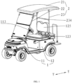
- FIG. 1 is a structural schematic view of a vehicle according to an embodiment of the present disclosure
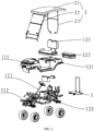
- FIG. 2 is an exploded view of the vehicle according to an embodiment of the present disclosure
- the vehicle includes a body assembly 1, an extension-retraction drive member (not shown), and a roof assembly 2.
- the body assembly 1 includes a front body 11 and a rear body 12.
- the front body 11 is slidably connected to the rear body 12 in a first direction (a Y direction shown in FIG. 1 ).
- a steering wheel 113 is connected to the front body 11, and a seat 123 is connected to the rear body 12.
- the extension-retraction drive member is disposed between and connected to the front body 11 and the rear body 12.
- the extension-retraction drive member is configured to drive the front body 11 and the rear body 12 to be extended or retracted in the first direction.
- the extension-retraction drive member may be an electric actuator, a cylinder, or the like.
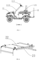
- FIG. 3 is a structural schematic view of the vehicle being retracted according to an embodiment of the present disclosure.
- the vehicle in the present disclosure has an extendable-retractable vehicle body.
- the vehicle body includes the front body 11 and the rear body 12.
- the extension-retraction drive member drives the front body 11 or the rear body 12 to move to adjust a distance between the front body and the rear body.
- a distance between the steering wheel 113 and the seat 123 may be adjusted by adjusting the distance between the front body and the rear body, such that various drivers having various heights may drive and operate the vehicle more comfortably.
- the distance between the front body and the rear body may be reduced to reduce a size of the vehicle body, such that the vehicle body may be transferred easily, and a cost of transferring the vehicle body may be reduced.
- the roof assembly 2 is detachably mounted on the body assembly 1.
- the roof assembly 2 includes a front bracket 22, a rear bracket 23, and an upper bracket 21.
- a bottom end of the front bracket 22 is rotationally connected to the front body 11.
- a top of the front bracket 22 is detachably connected to the upper bracket 21.
- a bottom of the rear bracket 23 is rotationally connected to the rear body 12.
- a top of the rear bracket 23 is detachably connected to the upper bracket 21.
- a foldable roof assembly 2 is further provided.
- the upper bracket 21, the front bracket 22 and the rear bracket 23 of the roof assembly 2 cooperatively forms a semi-enclosed structure supported above the body assembly 1 for sun shading and keeping the rain off.
- the front bracket 22 is configured to a front side the upper bracket 21, and the rear bracket 23 is configured to a rear side the upper bracket 21. Since the upper bracket 21 is detachably connected to the front bracket 22 and the rear bracket 23, when the upper bracket 21 is detached from the top of the front bracket 22 and the top of the rear bracket 23, the top of the front bracket 22 and the top of the rear bracket 23 are no longer fixed.
- FIG. 4 is a structural schematic view of the roof assembly being retracted according to an embodiment of the present disclosure.
- FIG. 5 is an exploded view of the bracket of the vehicle according to an embodiment of the present disclosure.
- the front body 11 includes a front frame 112 and a front covering member 111 covering the front frame 112.
- the rear body 12 includes a rear frame 122 and a rear covering member 121 covering the rear frame 122.
- the front frame 112 is connected to a first tube body 1121 extending along the first direction (Y-direction).
- the rear frame 122 is connected to a second tube body 1221 extending along the first direction.
- the first tube body 1121 is slidably connected to the second tube body 1221.
- the extension-retraction drive member 13 is an electric actuator. A driving end of the electric actuator is fixedly connected to the rear frame 122. The other end of the electric actuator away from the driving end is fixedly connected to the front frame 112.
- the electric actuator may be extended and retracted to drive the front frame and the rear frame to be extended and retracted relative to each other (i.e., drive the front frame and the rear frame to move relative to each other to adjust a distance between the front frame and the rear frame), such that the front body and the rear body are driven to be extended and retracted relative to each other (i.e., the distance between the front body and the rear body is reduced or increased).
- the front covering member 111 is slidably arranged inside the rear covering member 121.
- the first tube body 1121 may alternatively be slidably arranged insdie the second tube body 1221.
- the extension-retraction drive member 13 may alternatively be connected to the front covering member 111 and the rear covering member 121.
- the front frame 112 and the rear frame 122 may be slidably connected to each other by other means.
- the front frame 112 is connected with a slider
- the rear frame 122 is connected with a slide groove extending in the first direction. In this way, the distance between the front frame and the rear frame is adjusted by sliding the slider in the slide groove.
- the rear body 12 includes a limit pin 124 movably connected to the rear frame 122 and a limit plate 114 connected to the front frame 112.
- the limit plate 114 protrudes out of the front frame 112.
- the limit plate 114 defines a limit hole 1141 corresponding to the limit pin 124.
- the limit pin 124 is inserted into the limit hole 1141.
- a relative position of the front frame 112 and the rear frame 122 is fixed, and even if the extension-retraction drive member 13 is activated, the vehicle body cannot be extended or retracted, such that the user may drive and operate the vehicle safely.
- the limit pin 124 When the vehicle body is to be retracted, the limit pin 124 may firstly be pulled away from the limit hole 1141, and the extension-retraction drive member 13 is activated to drive the vehicle body to be extended and retracted.
- a tap switch may be arranged on the rear frame 122. The tap switch is signally connected to the extension-retraction drive member 13. In this way, when the limit pin 124 is detached from the limit hole 1141, the limit pin 124 triggers the tap switch to be on, the extension-retraction drive member 13 is able to be activated, and the vehicle body may be extended and retracted.
- the tap switch When the limit pin 124 is inserted into the limit hole 1141, the tap switch is off, and the extension-retraction drive member 13 is unable to be activated, such that the extension-retraction drive member 13 may be prevented from being activated when the limit pin 124 is being inserted. Reliability of the frame is improved.
- FIG. 6 is an exploded view of the roof assembly of the vehicle according to an embodiment of the present disclosure.
- a front support 115 is arranged on and protruding from the front body (not shown in FIG. 6 ).
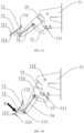
- FIG. 7a and FIG. 7b FIG. 7a to FIG. 7b are structural schematic views of various states of a connection between the bottom of the front bracket and a front support of the vehicle according to an embodiment of the present disclosure.
- a bottom of the front bracket 22 is inserted into a slot in the front support 115.
- the bottom end of the front bracket 22 defines a first rounded-rectangular hole 221 extending along an insertion direction.
- the front support 115 defines a through hole.
- a first rotation shaft 117 is inserted in the first rounded-rectangular hole 221 and the through hole.
- a bottom face of the slot is a limit face 1151 for restricting the front bracket 22 from rotating around the first rotation shaft 117.
- a first locking member 116 is inserted in the first rounded-rectangular hole 221.
- the front bracket 22 is fixedly connected to the front support 115 by the first locking member 116.
- the first locking member 116 is a locking bolt.
- the locking bolt passes through the first rounded-rectangular hole 221 to be threadedly connected to the front support 115. In this way, the front bracket 22 is fixed to the front support 115.
- the first locking member 116 may be detached (along the direction A in FIG.
- the front bracket 22 may be pulled out along a direction of first rounded-rectangular hole 221 away from the front support 115 (in the direction B in FIG. 7 a) . At this moment, an end surface of the front bracket 22 is away from the limit face 1151, and the front bracket 22 may be rotated in the direction C shown in FIG. 7b . In this way, the folding is completed. Since the folding may be performed only after the first locking member 116 being detached and subsequently the front bracket 22 being pulled out, the front bracket 22 may be positioned easily.
- the roof assembly 2 further includes a reinforcement member 223.
- An end of the reinforcement member 223 is fixedly connected to a portion of the front bracket 22 near the top, and the other end of the reinforcement member 223 extends upwardly towards the upper bracket 21 and is detachably connected to the upper bracket 21.
- six connecting posts 211 are arranged on and protruding from the upper bracket 21.
- Each connecting post 211 includes a tapered guide surface 2111 having a diameter gradually decreased along a direction away from the upper bracket 21.
- Two of the six connecting posts 211 are respectively inserted into tops of two sides of the front bracket 22; another two of the six connecting posts 211 are respectively inserted into tops of two sides of the reinforcement member 223; and the rest two of the six connecting posts 211 are respectively inserted into tops of two sides of the rear bracket 23.
- a diameter of an end of the connecting post 211 is small, and therefore, the connecting post 211 may be easily aligned to the front bracket 22, the reinforcement member 223, and the rear racket 23.
- the connecting post 211 is arranged with a connecting hook 2112.
- a connecting snap 212 is rotatably connected to each of the tops of the front bracket 22, the reinforcement member 223 and the rear bracket 23.
- the connecting hook 2112 may be snapped with the connecting hook 2112 to achieve fixation.
- the front bracket 22 is parallel to an end of the reinforcement member 223 near the upper bracket 21.
- the reinforcement member 223 may be connected to the rear bracket 23, and in this case, the rear bracket 23 is parallel to the end of the reinforcement member 223 near the upper bracket 21.
- the vehicle further includes a backrest 125.
- the backrest 125 is mounted on the rear body 12. Specifically, the backrest 125 may be mounted on a rear side of the seat 123.
- FIG. 8 is a structural schematic view of the backrest of the vehicle according to an embodiment of the present disclosure.
- Two third tube bodies 126 are connected to a bottom of the backrest 125.
- a rear support 127 is arranged on and protruding from the rear frame.
- the rear support 127 includes two fourth tube bodies 1271.
- Each third tube body 126 is inserted in one of the two fourth tube bodies 1271.
- Each third tube body 126 defines a second rounded-rectangular hole 1261.
- FIG. 9 FIG.
- FIG. 9 is a structural schematic view of a third rounded-rectangular hole according to an embodiment of the present disclosure.
- An angle ⁇ is generated between an extension direction of the rounded-rectangular hole 1261 (indicated by the dot-dash line in FIG. 9 ) and the insertion direction (indicated by the broken line in FIG. 9 ).
- the angle ⁇ is an acute angle.
- a diameter of the second rounded-rectangular hole 1261 gradually increases along a direction away from the backrest 125.
- the second rounded-rectangular hole 1261 is a conical inclined rounded-rectangular hole.
- the fourth tube body 1271 defines a through hole.
- a second rotation shaft 1263 is inserted in the second rounded-rectangular hole 1261 and the through hole.
- a first snap 1272 is rotationally connected to the fourth tube body 1271.
- the third tube body 126 is arranged with a first hook 1262 that may be snapped with the first snap 1272.
- the first snap 1272 may be rotated to be detached from the first hook 1262. Further, the backrest 125 may be pulled out along a direction of the second rounded-rectangular hole 1261 away from the rear support 127 (the D direction in FIG. 8 ).
- an engaging end of the second rotation shaft 1263 is moved from a small-diameter end of the second rounded-rectangular hole 1261 to a large-diameter end of the second rounded-rectangular hole 1261.
- the third tube body 126 gradually moves away from an inner wall of the fourth tube body 1271, such that the third tube body 126 does not attach to the inner wall of the fourth tube body 1271.
- the fourth tube body 1271 may not block the third tube body 126 from rotating. Therefore, the backrest 125 may be easily rotated forwardly to complete the folding.
- the second rounded-rectangular hole 1261 is a tapered inclined rounded-rectangular hole, and therefore, when the third tube body 126 is gradually inserted into the fourth tube body 1271, the second rounded-rectangular hole 1261 of the third tube body 126 is tightly engaged to the second rotation shaft 1263. A rear outer wall of the third tube body 126 is tightly pressed against a rear inner wall of the fourth tube body 1271. Therefore, the engaging is more tight.
- the second rounded-rectangular hole 1261 may be a flat and straight rounded-rectangular hole extending in the insertion direction.
- FIG. 10 is a structural schematic view of the rear bracket and the rear support of the vehicle according to an embodiment of the present disclosure.
- the rear bracket 23 is rotatably connected to the fourth tube body 1271 through a third rotation shaft 231.
- Two third rotation shafts 231 are arranged, and each of the two fourth tube bodies 1271 is arranged with one of the two third rotation shafts 231.
- the rear bracket 23 defines a limit slot 232 extending along an arc.
- a center of the arc is located on the third rotation shaft 231. That is, the limit slot 232 is an arc slot and is located at a front of the rear bracket 23.
- the arc slot is configured to limit a rotation angle and a rotation direction of the rear bracket 23.
- a radius angle corresponding to the arc slot is equal to the rotation angle of the rear bracket 23.
- a limit member 1273 is arranged on and protruding from one fourth tube body 1271. The limit member 1273 is received in the limit slot 232 to limit a rotation range of the rear bracket 23.
- the rear bracket 23 is fixedly connected to the fourth tube body 1271 by a second locking member 233.
- the second locking member 233 is a locking bolt. The locking bolt and the limit slot 232 are disposed on an end of the rear bracket 23 corresponding to each of the two fourth tube bodies 1271. After the second locking member 233 is removed, the rear bracket 23 is able to be rotated forwardly and folded towards the vehicle body.
- the steering wheel 113 includes a connecting tube 1131.
- the connecting tube 1131 is inserted in the front body 11.
- the connecting tube 1131 is secured to the front body 11 by a fastening bolt.
- the steering wheel 113 may be removed from the vehicle body after the fastening bolt is removed, such that more space is provided for folding the roof assembly (not shown in FIG. 3 ).
- the rear bracket 23 is further arranged with a reinforcing bar 234 configured to reinforce the rear bracket 23.
- the reinforcing bar 234 may be configured to place the steering wheel 113 when the rear bracket 23 is folded and the steering wheel 113 is detached.
- FIG. 11 is an exploded view of the pedal assembly of the vehicle according to an embodiment of the present disclosure.
- the pedal assembly 3 includes a rear pedal 31, arranged on the rear body 12.
- the rear pedal 31 is connected to a fifth tube body 311.
- a side of the rear body 12 away from the front body 11 is arranged with a sixth tube body 128.
- the fifth tube body 311 is inserted in the sixth tube body 128.
- the fifth tube body 311 defines a third rounded-rectangular hole 3111.
- the third rounded-rectangular hole 3111 extends in the insertion direction.
- a diameter of the third rounded-rectangular hole 3111 gradually decreases along a direction approaching the rear pedal 31.
- the sixth tube body 128 defines a through hole.
- a fourth rotation shaft 1282 is inserted in the third rounded-rectangular hole 3111 and the through hole.
- the fifth tube body 311 is rotatably connected with a second snap 32, and the sixth tube body 128 is arranged with a second hook 1281 snapped with the second snap 32.
- the rear seat 4 may be arranged at a rear of the vehicle body in order to increase the number of passenger seats.
- FIG. 12 is a structural schematic view of the rear seat and the pedal assembly of the vehicle according to an embodiment of the present disclosure.
- the rear seat 4 includes a storage basket 41 and a cover 42 rotatably connected to the storage basket 41. Articles may be stored in a storage space in the storage basket 41, and after the cover 42 is closed to the storage basket 41, passengers may sit on the cover.
- the pedal assembly 3 is disposed at a rear of the vehicle body.
- the rear pedal 31 serves as a footrest for a passenger sitting at the rear of the vehicle.
- the rear pedal 31 is foldable.
- the second snap 32 may be rotated to be disengaged from the second hook 1281.
- the rear pedal 31 may be pulled out along a direction of the third rounded-rectangular hole 3111 away from the sixth tube body 128.
- an engaging end of the fourth rotation shaft 1282 is moved from a small-diameter end of the third rounded-rectangular hole 3111 to a large-diameter end of the third rounded-rectangular hole 3111, and the fifth tube body 311 is gradually moved away from the sixth tube body 128.
- the sixth tube body 128 may not block the fifth tube body 311 from rotating. In this way, the rear pedal 31 is rotated downwardly to complete the folding.
- the third rounded-rectangular hole 3111 is a tapered rounded-rectangular hole, and therefore, while the fifth tube body 311 is gradually inserted into the sixth tube body 128, the fourth rotation shaft 1282 is tightly fitted to the third rounded-rectangular hole 3111.
- the third rounded-rectangular hole 3111 may be a flat and straight rounded-rectangular hole extending in the insertion direction.
- the pedal assembly 3 further includes an armrest 33.
- the armrest 33 is arranged on the rear pedal 31.
- the armrest 33 is connected to a seventh tube body 331.
- An eighth tube body 312 is connected to a side of the rear pedal 31 away from the rear body.
- the seventh tube body 331 is inserted in the eighth tube body 312.
- the seventh tube body 331 defines a fourth rounded-rectangular hole 3311.
- An angle is formed between an extension direction of the fourth rounded-rectangular hole 3311 and the insertion direction. The angle may be an acute angle.
- the eighth tube body 312 defines a through hole.
- a fifth rotation shaft 313 is inserted in the fourth rounded-rectangular hole 3311 and the through hole.
- a third snap 314 is rotatably connected to the eighth tube body 312, and the seventh tube body 331 is arranged with a third hook 3312 snapped with the third snap 314.
- a tube clamp 1283 is arranged at a side of the eighth tube body 312 near of the rear pedal 31. The tube clamp 1283 defines an opening facing away from the eighth tube body 312. The tube clamp 1283 is snapped with the armrest 33.
- the armrest 33 may also be folded.
- the third snap 314 may be rotated to be detached from the third hook 3312, and the armrest 33 may be pulled out in a direction of the fourth rounded-rectangular hole 3311 away from the eighth tube body 312. Since the fourth rounded-rectangular hole 3311 is a taper inclined rounded-rectangular hole, the eighth tube body 312 may not block the seventh tube body 331 from rotating while the seventh tube body 331 is gradually moving away from the eighth tube body 312. At this moment, the armrest 33 may be rotated counterclockwise easily, and the folding is completed. Further, the armrest 33 may be fixed by being snapped inside the tube clamp 1283. As shown in FIG. 13, FIG.
- FIG. 13 is a structural schematic view of the pedal assembly after being folded according to an embodiment of the present disclosure.
- a plane on which the rear pedal 31 is located is substantially parallel to the armrest 33.
- the rear pedal 31 and the armrest 33 are both affixed to the rear of the vehicle body, such that the space occupied by the vehicle is reduced.
- the fourth rounded-rectangular hole 3311 may be a flat and straight rounded-rectangular hole extending along the insertion direction.
- FIG. 14 is a structural schematic view of the vehicle when being completely folded according to an embodiment of the present disclosure. Compared to the fully unfolded structure of the vehicle shown in FIG. 1 , the size of the vehicle after being folded is significantly reduced, such that the vehicle may be transferred easily, and the transferring costs may be reduced.
- the vehicle further includes a braking system.
- the braking system includes a brake (not shown) and a brake pedal assembly.
- FIG. 15 is a structural schematic view of the brake pedal assembly according to an embodiment of the present disclosure
- FIG. 16 is an exploded view of the brake pedal assembly according to an embodiment of the present disclosure.
- the brake pedal assembly 5 is disposed at the bottom of the front body and includes a bracket 51, a brake pedal 52 and a parking pedal 53.
- the bracket 51 is fixed to the front body.
- the bracket 51 is arranged with a parking block 54.
- the parking block 54 defines a groove 541.
- the brake pedal 52 is rotatably connected to the bracket 51.
- the brake pedal 52 is connected to a parking hook 55 snapped with the groove 541.
- the brake pedal 52 may drive the brake to perform braking.
- the parking pedal 53 is rotatably connected to the brake pedal 52.
- the parking pedal 53 is coupled with the parking hook 55.
- the parking pedal 53 may drive the parking hook 55 to snap with the groove 541.
- the brake pedal 52 When the brake pedal 52 is rotating in the first direction (the first direction may be a direction of the brake pedal 52 being stepped down), the brake pedal 52 controls the brake to perform braking.
- the parking pedal 53 In a braking state, the parking pedal 53 is rotating in the second direction (the second direction may be a direction of the parking pedal 53 being stepped) with respect to the brake pedal 52.
- the parking pedal 53 drives the parking hook 55 to be snapped with the groove 541 of the parking block 54. Since the parking gear block 54 is arranged on the bracket 51 and the parking hook 55 is connected to the brake pedal 52, the brake pedal 52 is fixed and is maintained at the braking state. In this way, parking is performed.
- the brake pedal assembly integrates braking and parking functions, a space of the driver compartment for receiving a handbrake may be saved, space utilization may be improved. In addition, retraction of the vehicle body may not be affected by the handbrake, the vehicle body may be retracted more severely into an even smaller size. Furthermore, since the brake pedal 52 and the parking pedal 53 are configured as a one-piece and integral structure, braking and parking may be achieved by stepping on the pedal only.
- the parking block 54 is disposed at a bottom of the bracket 51.
- a plurality of grooves 541 may be defined.
- the plurality of grooves 541 are arranged along a direction of the brake pedal 52 approaching the bracket 51.
- a trajectory formed by the plurality of grooves 541 is an arc protruding in a direction away from the bracket 51. Since the parking block 54 defines the plurality of grooves 541, the brake pedal 52 may be fixed by the parking hook 55 being snapped with any one of the plurality of grooves 541. Therefore, the brake pedal 52 may be fixed by the parking hook 55 in a wide range of rotation. Regardless of the extent of the parking pedal 53 being stepped, the parking may always be achieved by stepping the parking pedal 53.
- the parking hook 55 may be snapped with one of the plurality of grooves 541 disposed near the brake pedal 52.
- the parking hook 55 may be snapped with one of the plurality of grooves 541 disposed away from the brake pedal 52. Therefore, parking can always be achieved, and less structural precision is required to achieve the parking, operations may be increased more easily.
- a width of the groove 541 gradually decreases in a direction from the opening to the groove body, such that the parking hook 55 may be extended into the groove 541 more easily, difficulty of snapping may reduced. In order to further reduce the difficulty of snapping, the width of the parking hook 55 gradually increases from the free end to the root.
- the brake pedal assembly 5 further includes a first reset spring 521.
- the first reset spring 521 is connected between the bracket 51 and the brake pedal 52.
- the first reset spring 521 is configured to apply a force to the brake pedal 52 to enable the brake pedal 52 to rotate in a direction opposite to the first direction.
- the bracket 51 is arranged with a sixth rotation shaft 522.
- the brake pedal 52 is rotatably arranged on the sixth rotation shaft 522.
- the first reset spring 521 is a torsion spring.
- the first reset spring 521 sleeves the sixth rotation shaft 522.
- the brake pedal assembly 5 further includes a second reset spring 551.
- the second reset spring 551 is connected between the parking hook 55 and the brake pedal 52.
- the second reset spring 551 is configured to apply a force to the parking hook 55 to enable the parking hook 55 to rotate in a direction opposite to the second direction.
- the brake pedal 52 is arranged with a seventh rotation shaft 552.
- the parking hook 55 is rotatably arranged on the seventh rotation shaft 552.
- the second reset spring 551 is a torsion spring.
- the second reset spring 551 sleeves the seventh rotation shaft 552.
- the brake pedal 52 is arranged with an eighth rotation shaft 531.
- the parking pedal 53 is rotatably arranged on the eighth rotation shaft 531.
- the brake pedal assembly 5 further includes a connecting rod 56. Two ends of the connecting rod 56 are respectively rotatably connected to the parking pedal 53 and the parking hook 55.
- the parking pedal 53 is coupled to the parking hook 55 through a linking rod.
- the linking rod may be simple, and synchronous action may be achieved by the linking rod efficiently.
- Rotation of the parking hook 55 is achieved by stepping the parking pedal 53.
- the parking pedal 53 and the parking hook 55 may also be linked by other transmission structures.
- the linkage may be achieved by a gear set between the parking pedal 53 and the parking hook 55. When the parking pedal 53 is rotated in the second direction, the gear set is driven to rotate to further drive the parking hook 55 to rotate.
- the first reset spring 521 drives the brake pedal 52 to be reset.
- the brake pedal 52 rotates around the sixth rotation shaft 522 to be reset to an original position, and the brake no longer applies the brake.
- the first reset spring 521 provides a rebound force for the brake pedal 52 in the direction opposite to the first direction, such that the parking hook 55 always abuts against an inner wall of the groove 541, the parking hook 55 may not be disengaged from the groove 541, and a parking state is maintained.
- the first reset spring 521 may be an elastic structure such as a tension spring.
- the second reset spring 551 drives the parking pedal 53 to be reset, and the parking pedal 53 rotates around the seventh rotation shaft 552 to be reset to an original position.
- the second reset spring 551 may be an elastic structure such as a tension spring.
- FIG. 17a to FIG. 17c are structural schematic views of various states of the brake pedal assembly according to an embodiment of the present disclosure.
- the brake pedal 52 includes a first pedal surface 523 and a brake limit surface 524 opposite to the first pedal surface 523.
- the parking pedal 53 includes a second pedal surface 532.
- the brake limit surface 524 is configured to limit the parking pedal 53 from rotating in the direction opposite to the second direction. In this way, when the brake pedal 52 and the parking pedal 53 are at rest relative to each other, the first pedal surface 523 is aligned with the second pedal surface 532.
- a structure of the brake pedal 52 being not stepped is shown in FIG. 3a.
- the first pedal surface 523 of the brake pedal 52 facing the driver's foot bottom is aligned with the second pedal surface 532 of the parking pedal 53 facing the driver's foot bottom.
- surfaces of the brake pedal assembly contacting the foot bottom include the first pedal surface 523 and the second pedal surface 532.
- a relatively large contact area is achieved, and the driver may apply the force for stepping the brake pedal easily.
- the parking hook 55 is located away from the parking block 54 on the bracket 51. Even if the parking pedal 53 is mistakenly stepped, the parking hook 55 cannot be snapped with the groove 541 of the parking block 54, and rotation of the brake pedal 52 may not be affected.
- FIG. 17b A state of the brake pedal 52 being stepped is shown in FIG. 17b .
- the brake pedal 52 When the brake pedal 52 is rotating in the first direction (X-direction, counterclockwise) taking the sixth rotation shaft 522 as the rotation axis, the brake pedal 52 remains stationary relative with the parking pedal 53, and the first pedal surface 523 is aligned with the second pedal surface 532. In this state, the brake pedal 52 is disposed closer to the bracket 51, and therefore, the parking hook 55 on the brake pedal 52 is driven to approach the parking block 54 on the bracket 51.
- FIG. 17c shows the parking pedal 53 being stepped while the brake pedal 52 is stepped.
- the brake pedal 52 remains close to the bracket 51 in FIG. 17b .
- the brake continues to brake, whereas the parking pedal 53 rotates relative to the brake pedal 52 in a second direction (Y-direction., clockwise) taking the eighth rotation shaft 531 as the rotation axis.
- the parking pedal 53 pulls the connecting rod 56, such that the parking hook 55 is driven to rotate counterclockwise taking the seventh rotation shaft 552 as the rotation axis, until the parking hook 55 is snapped into the groove 541.
- the brake pedal 52 may always have, under the action of the first reset spring (not shown in FIG.
- the second pedal surface 532 is located on a side of the first pedal surface 523 near the bracket 51. That is, when the driver's foot steps on the brake pedal 52 and the parking pedal 53, the first pedal surface 523 is disposed closer to the driver's toe. Therefore, while the driver is using the foot bottom to step on the brake pedal 52, the driver may simultaneously use the toe of the foot to drive the parking pedal 53 to rotate. The operation is more easy. When the driver only needs to perform a braking operation, the driver may use the toe to step on the second pedal surface 532 to prevent the parking pedal 53 from being stepped mistakenly.
- an area of the second pedal surface 532 is larger than an area of the first pedal surface 523. Since braking operations may be performed more frequently than parking operations, increasing the area of the second pedal surface 532 allows the braking operations to be performed more easily and reduces the probability of accidentally touching the parking pedal 53.
Landscapes
- Engineering & Computer Science (AREA)
- Transportation (AREA)
- Mechanical Engineering (AREA)
- Chemical & Material Sciences (AREA)
- Combustion & Propulsion (AREA)
- Physics & Mathematics (AREA)
- General Physics & Mathematics (AREA)
- Automation & Control Theory (AREA)
- Body Structure For Vehicles (AREA)
Applications Claiming Priority (2)
| Application Number | Priority Date | Filing Date | Title |
|---|---|---|---|
| CN202310954856.1A CN117184235A (zh) | 2023-07-31 | 2023-07-31 | 车辆 |
| CN202322039677.3U CN220465616U (zh) | 2023-07-31 | 2023-07-31 | 车辆 |
Publications (1)
| Publication Number | Publication Date |
|---|---|
| EP4501751A1 true EP4501751A1 (de) | 2025-02-05 |
Family
ID=88647617
Family Applications (1)
| Application Number | Title | Priority Date | Filing Date |
|---|---|---|---|
| EP23207057.3A Pending EP4501751A1 (de) | 2023-07-31 | 2023-10-31 | Fahrzeug |
Country Status (1)
| Country | Link |
|---|---|
| EP (1) | EP4501751A1 (de) |
Citations (9)
| Publication number | Priority date | Publication date | Assignee | Title |
|---|---|---|---|---|
| US3770289A (en) * | 1968-03-20 | 1973-11-06 | L Dougherty | Collapsible vehicle |
| US4340124A (en) * | 1980-03-12 | 1982-07-20 | Leonard Lloyd H | Foldable minicar |
| DE19756307A1 (de) * | 1997-12-09 | 1999-06-17 | Iourii Gribov | Motorgetriebenes Fahrzeug mit variabler Geometrie der Karosserie |
| US6793248B1 (en) * | 2002-12-24 | 2004-09-21 | Genemax Medical Products Industry Corp. | Adjustable chassis of an electric cart |
| US9199672B1 (en) * | 2014-07-09 | 2015-12-01 | Hyundai Motor Company | Link unit for foldable vehicle |
| US9415813B2 (en) * | 2014-07-09 | 2016-08-16 | Hyundai Motor Company | Foldable vehicle |
| EP2537722B1 (de) * | 2011-06-21 | 2020-06-24 | Iseki & Co., Ltd. | Parksperrmechanismus und Nutzfahrzeug |
| US11407451B1 (en) * | 2021-02-23 | 2022-08-09 | Textron Innovations Inc. | Canopy for lightweight vehicle |
| CN114906105A (zh) * | 2022-05-12 | 2022-08-16 | 柳州五菱汽车工业有限公司 | 一种复合踏板装置及车辆 |
-
2023
- 2023-10-31 EP EP23207057.3A patent/EP4501751A1/de active Pending
Patent Citations (9)
| Publication number | Priority date | Publication date | Assignee | Title |
|---|---|---|---|---|
| US3770289A (en) * | 1968-03-20 | 1973-11-06 | L Dougherty | Collapsible vehicle |
| US4340124A (en) * | 1980-03-12 | 1982-07-20 | Leonard Lloyd H | Foldable minicar |
| DE19756307A1 (de) * | 1997-12-09 | 1999-06-17 | Iourii Gribov | Motorgetriebenes Fahrzeug mit variabler Geometrie der Karosserie |
| US6793248B1 (en) * | 2002-12-24 | 2004-09-21 | Genemax Medical Products Industry Corp. | Adjustable chassis of an electric cart |
| EP2537722B1 (de) * | 2011-06-21 | 2020-06-24 | Iseki & Co., Ltd. | Parksperrmechanismus und Nutzfahrzeug |
| US9199672B1 (en) * | 2014-07-09 | 2015-12-01 | Hyundai Motor Company | Link unit for foldable vehicle |
| US9415813B2 (en) * | 2014-07-09 | 2016-08-16 | Hyundai Motor Company | Foldable vehicle |
| US11407451B1 (en) * | 2021-02-23 | 2022-08-09 | Textron Innovations Inc. | Canopy for lightweight vehicle |
| CN114906105A (zh) * | 2022-05-12 | 2022-08-16 | 柳州五菱汽车工业有限公司 | 一种复合踏板装置及车辆 |
Similar Documents
| Publication | Publication Date | Title |
|---|---|---|
| JPH0721389Y2 (ja) | 車載用の補助座席 | |
| CN102712271B (zh) | 用于交通工具座椅的靠背翻转机构 | |
| US20120013103A1 (en) | Quick-lock motorcycle fold-up structure | |
| CN1765653A (zh) | 可缩进地板内的座椅 | |
| EP4501751A1 (de) | Fahrzeug | |
| US11458869B2 (en) | Vehicle seat | |
| US20210024163A1 (en) | Kick scooter and method for operating a scooter | |
| JP2502925Y2 (ja) | 座席姿勢調整装置 | |
| CN110001463B (zh) | 自动解锁机构及包含其的汽车座椅 | |
| CN209107843U (zh) | 自动或手动收折的切换机构 | |
| CN220465616U (zh) | 车辆 | |
| CN219838472U (zh) | 一种汽车座椅 | |
| CN216684161U (zh) | 一种汽车座椅便捷进入调节结构 | |
| US12246625B2 (en) | Seating assembly with displaceable panel | |
| KR100657858B1 (ko) | 휴대용 자전거 | |
| CN108189933B (zh) | 电动自行车错位停放系统 | |
| CN1412040A (zh) | 带有可暂停座椅向后移动的辅助锁定机构的滑动汽车座椅 | |
| CN214564786U (zh) | 汽车座椅高强度滑轨 | |
| CN117184235A (zh) | 车辆 | |
| CN220662323U (zh) | 一种重型汽车座椅 | |
| JPH1085260A (ja) | 車椅子搭乗用輸送装置 | |
| JP3646257B2 (ja) | 電動車用ルーフ装置 | |
| CN212423361U (zh) | 一种滑板车 | |
| CN115535118B (zh) | 折叠座椅及折叠车 | |
| CN220905237U (zh) | 一种折叠滑板车 |
Legal Events
| Date | Code | Title | Description |
|---|---|---|---|
| PUAI | Public reference made under article 153(3) epc to a published international application that has entered the european phase |
Free format text: ORIGINAL CODE: 0009012 |
|
| STAA | Information on the status of an ep patent application or granted ep patent |
Free format text: STATUS: THE APPLICATION HAS BEEN PUBLISHED |
|
| AK | Designated contracting states |
Kind code of ref document: A1 Designated state(s): AL AT BE BG CH CY CZ DE DK EE ES FI FR GB GR HR HU IE IS IT LI LT LU LV MC ME MK MT NL NO PL PT RO RS SE SI SK SM TR |
|
| STAA | Information on the status of an ep patent application or granted ep patent |
Free format text: STATUS: REQUEST FOR EXAMINATION WAS MADE |
|
| 17P | Request for examination filed |
Effective date: 20250213 |